EP1885091A2 - Paketverarbeitungsvorrichtung mit Ladungskontrollmechanismus auf Grundlage der Paketlänge und der vergangenen CPU-Zeit - Google Patents
Paketverarbeitungsvorrichtung mit Ladungskontrollmechanismus auf Grundlage der Paketlänge und der vergangenen CPU-Zeit Download PDFInfo
- Publication number
- EP1885091A2 EP1885091A2 EP20070111285 EP07111285A EP1885091A2 EP 1885091 A2 EP1885091 A2 EP 1885091A2 EP 20070111285 EP20070111285 EP 20070111285 EP 07111285 A EP07111285 A EP 07111285A EP 1885091 A2 EP1885091 A2 EP 1885091A2
- Authority
- EP
- European Patent Office
- Prior art keywords
- packet
- processing time
- packet length
- connection
- length
- Prior art date
- Legal status (The legal status is an assumption and is not a legal conclusion. Google has not performed a legal analysis and makes no representation as to the accuracy of the status listed.)
- Granted
Links
Images




Classifications
-
- H—ELECTRICITY
- H04—ELECTRIC COMMUNICATION TECHNIQUE
- H04L—TRANSMISSION OF DIGITAL INFORMATION, e.g. TELEGRAPHIC COMMUNICATION
- H04L47/00—Traffic control in data switching networks
- H04L47/10—Flow control; Congestion control
- H04L47/35—Flow control; Congestion control by embedding flow control information in regular packets, e.g. piggybacking
-
- H—ELECTRICITY
- H04—ELECTRIC COMMUNICATION TECHNIQUE
- H04L—TRANSMISSION OF DIGITAL INFORMATION, e.g. TELEGRAPHIC COMMUNICATION
- H04L49/00—Packet switching elements
- H04L49/90—Buffering arrangements
-
- H—ELECTRICITY
- H04—ELECTRIC COMMUNICATION TECHNIQUE
- H04W—WIRELESS COMMUNICATION NETWORKS
- H04W28/00—Network traffic management; Network resource management
- H04W28/02—Traffic management, e.g. flow control or congestion control
- H04W28/0247—Traffic management, e.g. flow control or congestion control based on conditions of the access network or the infrastructure network
-
- H—ELECTRICITY
- H04—ELECTRIC COMMUNICATION TECHNIQUE
- H04W—WIRELESS COMMUNICATION NETWORKS
- H04W28/00—Network traffic management; Network resource management
- H04W28/02—Traffic management, e.g. flow control or congestion control
- H04W28/0284—Traffic management, e.g. flow control or congestion control detecting congestion or overload during communication
-
- H—ELECTRICITY
- H04—ELECTRIC COMMUNICATION TECHNIQUE
- H04W—WIRELESS COMMUNICATION NETWORKS
- H04W8/00—Network data management
- H04W8/02—Processing of mobility data, e.g. registration information at HLR [Home Location Register] or VLR [Visitor Location Register]; Transfer of mobility data, e.g. between HLR, VLR or external networks
- H04W8/04—Registration at HLR or HSS [Home Subscriber Server]
Definitions
- the present invention relates to packet processing devices and more particularly to a packet processing device that processes packets with firmware of a central processing unit (CPU).
- CPU central processing unit
- Radio network controller an upper-level station that manages base stations
- RNC radio network controller
- the Japanese Patent Application Publication No. 2004-007256 paragraphs Nos. 0020 to 0035 and FIG. 1 proposes a technique of controlling packet transmission based on packet lengths.
- a packet routing device calculates a suspend time from the lengths of received packets and sends back a suspend packet containing the calculated suspend time, so that the sender will suspend transmission of next packets for the specified suspend time.
- Such packet processing devices process packets whose length varies from packet to packet.
- the number of packets depends, in general, on the packet length. To be more specific, the traffic may actually be a small number of long packets. Or it many be a large number of short packets. In the latter case, the packet processing device has to process packet headers more often than in the former case. This results in an excessive overhead of packet processing, which consumes more CPU-time resources than in the case of long packets, consequently affecting control tasks for other subsystems in the device.
- An embodiment of the present invention may provide an apparatus for processing packets which is formed from the following elements: a packet buffer, a packet processor, a packet length monitor, a management table, a processing time monitor, and a processed packet sender.
- the packet buffer buffers either first packets on a first connection or second packets on a second connection that is different from the first connection.
- the packet buffer initially focuses on the first connection and checks a packet length flag and a processing time flag to observe the condition of packet processing for the first connection. When neither of the two flags are on, the packet buffer keeps buffering the first packets on the first connection.
- the packet buffer changes focus from the first connection to the second connection and begins buffering the second packets on the second connection.
- the packet processor processes a packet read out of the packet buffer, thus outputting a processed packet.
- the processed packet sender outputs this processed packet to an external link.
- the packet length monitor calculates a new cumulative packet length by adding a length of the processed packet to a cumulative sum of lengths of past processed packets.
- the packet length monitor turns on the packet length flag if the new cumulative packet length is greater than a predetermined packet length threshold.
- the management table stores values of packet length ranges and processing time estimates in an associated manner.
- the packet length ranges are ranges of packet lengths
- the processing time estimate corresponding to a particular packet length range refers to an estimated time for processing a packet with a length falling within that packet length range.
- the processing time monitor searches the management table to find a processing time estimate corresponding to the packet length of the processed packet, calculates a new cumulative processing time estimate by adding the found processing time estimate to a cumulative sum of processing time estimates of past packets. If the new cumulative processing time estimate is greater than a predetermined processing time threshold, the processing time monitor turns on the processing time flag.
- FIG. 1 is a conceptual view of a packet processing device according to an embodiment of the present invention.
- This packet processing device 10 is formed from a packet buffer 11, a packet processor 12, a packet length monitor 13, a management table 14, a processing time monitor 15, and a processed packet sender 16.
- a maintenance console 30 can be attached to the packet processing device 10.
- the packet buffer 11 buffers either first packets on a first connection or second packets on a second connection that is different from the first connection.
- the packet buffer 11 initially focuses on the first connection and checks a packet length flag and a processing time flag to observe the condition of packet processing for the first connection. When neither of the two flags are on (in other words, if both flags are off), the packet buffer keeps buffering the first packets on the first connection. When either the packet length flag or the processing time flag or both are on, the packet buffer 11 changes focus from the first connection to the second connection and begins buffering second packets on the second connection.
- the packet processor 12 processes a packet read out of the packet buffer 11, thus outputting a processed packet.
- the packet length monitor 13 adds the length of this processed packet to a cumulative sum of the lengths of past packets, thus outputting a new cumulative packet length.
- the packet length monitor 13 turns on a packet length flag if the new cumulative packet length is greater than a packet length threshold that is defined previously.
- the packet length threshold is given from an external source (e.g., maintenance console 30) through an external command interface (not shown) .
- the management table 14 manages information called "packet length ranges" and "processing time estimates” in an associated manner.
- Packet length ranges are ranges of packet lengths.
- the processing time estimate corresponding to a particular packet length range is an estimated time for processing a packet with a length falling within that packet length range.
- the processing time monitor 15 searches the management table 14 to find a processing time estimate corresponding to the packet length of the processed packet and calculates a new cumulative processing time estimate by adding the found processing time estimate to a cumulative sum of processing time estimates of the past packets. If the new cumulative processing time estimate is greater than a predetermined processing time threshold, then the processing time monitor 15 turns on a processing time flag.
- the processed packet sender 16 receives the processed packet from the packet processor 12 and outputs it to an external link.
- the processing time threshold is given from an external source (e.g., maintenance console 30) through an external command interface (not shown).
- the packet processing device 10 described above can be applied to a user plane protocol converter that controls traffic of user plane.
- the user plane carries voice, images, and other data, as opposed to the control plane carrying control information.
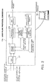
- FIG. 2 shows a configuration of a user plane protocol converter 10a. Some elements of this user plane protocol converter 10a are common to those of the packet processing device 10 shown in FIG. 1, the explanation for which will not be repeated here.
- the user plane protocol converter 10a is part of a radio network controller (RNC) on a mobile communications network, responsible for processing packet traffic between the network and mobile stations.
- RNC radio network controller
- the user plane protocol converter 10a is formed from the following elements: PHY (physical layer) modules 16a and 17, a packet buffer 11, a protocol converter 12a, a packet length monitor 13, a management table 14, and a processing time monitor 15.
- PHY physical layer
- the PHY module 17 receives packets arriving through downlink connections (network to mobile stations) and uplink connections (mobile stations to network), thus terminating the physical layer and asynchronous transfer mode (ATM) layer.
- ATM asynchronous transfer mode
- the PHY module 16a is equivalent to what is shown in FIG. 1 as the processed packet sender 16.
- the PHY module 16a converts the signal format of outgoing packets so that they will comply with the physical layer and ATM layer specifications.
- the protocol converter 12a is equivalent to what is shown in FIG. 1 as the packet processor 12.
- the protocol converter 12a contains a CPU to convert the protocol of packets flowing in the downlink direction (network to mobile stations) as well as those in the uplink direction (mobile stations to network).
- the downlink protocol conversion is a packet processing task that converts an upper-layer packet format to a lower-layer packet format.
- the uplink protocol conversion is another packet processing task, which converts a lower-layer packet format to an upper-layer packet format.
- FIG. 3 shows a protocol stack. This model involves a UE (user equipment, or mobile station) 21, a node-B (or base station) 22, an RNC 23, and a core network 24 linked in that order.
- the above-described user plane protocol converter 10a is implemented as part of the RNC 23.
- the user plane protocol converter 10a contains two protocol stacks; one is coupled to the node-B 22 and the other is coupled to the core network 24.
- the former protocol stack begins with PHY at the bottommost layer, on top of which are ATM, AAL2 IurFP, MAC, and RLC in that order.
- AAL2 is the acronym for "ATM adaptation layer 2.”
- IurFP refers to "Iur Frame Protocol,” which provides a logical interface between RNCs.
- MAC is the acronym of "Media Access Control” and RLC "Radio Link Control.”
- the latter protocol stack begins with PHY at the bottommost layer, on top of which are ATM, AAL5, IuUP, IP, UDP, and GTP-U in that order.
- IuUP means "Iu User Plane Protocol.”
- IP is the acronym of "Internet Protocol,” UDP “User Datagram Protocol,” and GTP-U “GPRS Tunneling Protocol-User'” where GPRS means "General Packet Radio Service.”
- PHY and ATM are implemented as hardware layers of the RNC 23 while the other layers are provided by CPU firmware.
- FIG. 4 shows an example of the management table 14.
- the illustrated management table 14 has two data fields titled "Packet Length Range” and "CPU Time Estimate,” the latter field corresponding to the processing time estimates discussed in an earlier section.
- the protocol converter 12a has processed a packet and that the resulting processed packet has a length that falls within the range of 101 bytes to 500 bytes.
- the management table 14 permits the protocol converter 12a to consider that the CPU has consumed about 60 ⁇ s to convert the protocol of that particular packet.
- the management table 14 may be compiled from packet length range and CPU time estimate field values given from an external source (e.g., maintenance console 30) through an external device interface (not shown).
- an external source e.g., maintenance console 30
- an external device interface not shown
- the processing time monitor 15 consults the management table 14 to seek a packet length range that a given packet length falls in. Each time this happens, the processing time monitor 15 increments a counter corresponding to the found packet length range.
- the processing time monitor 15 have the function of automatically updating the packet length ranges and corresponding processing time estimates, according to the current traffic condition indicated by current values of the counters.
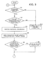
- the present embodiment monitors the length and CPU time of each processed packet when a particular connection (downlink connection in the above example) is selected for protocol conversion. If either of those parameters exceeds a given threshold, the corresponding flag (packet length flag, processing time flag) is turned on. The "on" state of those flags means that the currently selected connection (e.g., downlink connection) is imposing a heavy packet processing load on the CPU. The focus of packet processing is thus moved to another connection (e.g., uplink connection). Before moving the focus from one connection C1 to another connection C2, the packet processing device saves the context of packet processing for the connection C1. When the focus returns to the original connection C1, the packet processing device uses the saved packet processing context to resume the interrupted processing.
- a particular connection downlink connection in the above example
- the corresponding flag packet length flag, processing time flag
- the switching of connections may take place from one downlink connection D1 to another downlink connection D2.
- the switching may take place from one uplink connection U1 to another uplink connection U2.
- steps S1 to S10 may be applied to a plurality of downlink connections D1 to Dn, one round for each connection, until either or both flags are turned on.
- the focus moves to a plurality of uplink connections U1 to Un.
- the process of steps S1 to S10 is now applied to those uplink connections U1 to Un, one round for each connection.
- the packet processing device 10 regulates the CPU time consumption for protocol conversion of received packets, no matter how the packet length or the number of established connections may vary, thus avoiding the problem of CPU hang-up.
- the present invention prevents CPU time resources from being occupied by packet processing, so that other control tasks can keep running. In other words, the present invention helps to maintain the load balance between the components of the device.
- the proposed packet processing device allows its packet length threshold and processing time threshold, as well as packet length ranges and CPU time estimates in the management table 14, to be defined through an external control command interface. This feature gives flexibility to operations and maintenance of the system.
- the processing time monitor 15 checks the number of processed packets at certain intervals, for each packet length range. Depending on the current traffic condition observed in this way, the processing time monitor 15 automatically updates the packet length ranges and their corresponding processing time estimates. With this feature of the processing time monitor 15, the packet processing device 10 can modifies its operating parameters in a realtime fashion.
- the present invention provides a packet processing device designed to recognize the current CPU load not only from packet lengths, but also from estimated packet processing times. To achieve this, the packet processing device accumulates the length of packets that it has processed and turns on a packet length flag if that cumulative packet length exceeds a threshold. It also consults a management table to find a processing time estimate corresponding to the length of a processed packet, and if the cumulative sum of such processing time estimates is greater than a threshold, then it turns on a processing time flag. The packet processing device leaves the current connection and turns to another connection when either the packet length flag or the processing time flag or both are set to on. This feature enables the packet processing device to control its own processing workload more adequately and thus achieves stable operation and improved quality of communication service.
- the invention also provides a computer program or a computer program product for carrying out any of the methods described herein, and a computer readable medium having stored thereon a program for carrying out any of the methods described herein.
- a computer program embodying the invention may be stored on a computer-readable medium, or it could, for example, be in the form of a signal such as a downloadable data signal provided from an Internet website, or it could be in any other form.
Landscapes
- Engineering & Computer Science (AREA)
- Computer Networks & Wireless Communication (AREA)
- Signal Processing (AREA)
- Databases & Information Systems (AREA)
- Data Exchanges In Wide-Area Networks (AREA)
Applications Claiming Priority (1)
| Application Number | Priority Date | Filing Date | Title |
|---|---|---|---|
| JP2006200358A JP4509068B2 (ja) | 2006-07-24 | 2006-07-24 | パケット処理装置 |
Publications (3)
| Publication Number | Publication Date |
|---|---|
| EP1885091A2 true EP1885091A2 (de) | 2008-02-06 |
| EP1885091A3 EP1885091A3 (de) | 2008-04-09 |
| EP1885091B1 EP1885091B1 (de) | 2011-03-23 |
Family
ID=38884649
Family Applications (1)
| Application Number | Title | Priority Date | Filing Date |
|---|---|---|---|
| EP20070111285 Ceased EP1885091B1 (de) | 2006-07-24 | 2007-06-28 | Paketverarbeitungsvorrichtung mit Ladungskontrollmechanismus auf Grundlage der Paketlänge und der vergangenen CPU-Zeit |
Country Status (5)
| Country | Link |
|---|---|
| US (1) | US7796609B2 (de) |
| EP (1) | EP1885091B1 (de) |
| JP (1) | JP4509068B2 (de) |
| CN (1) | CN101163101B (de) |
| DE (1) | DE602007013320D1 (de) |
Cited By (1)
| Publication number | Priority date | Publication date | Assignee | Title |
|---|---|---|---|---|
| US20140189083A1 (en) * | 2012-12-28 | 2014-07-03 | Telefonaktiebolaget L M Ericsson (Publ) | Method and system for packet job scheduler in data processing based on workload self-learning |
Families Citing this family (4)
| Publication number | Priority date | Publication date | Assignee | Title |
|---|---|---|---|---|
| US8873438B2 (en) * | 2010-09-29 | 2014-10-28 | Infosys Limited | Method and system for adaptive aggregation of data in a wireless sensor network |
| WO2013030908A1 (ja) * | 2011-08-26 | 2013-03-07 | 富士通株式会社 | スケジューリングシステム、データ処理システムおよびスケジューリング方法 |
| US12008444B2 (en) * | 2020-06-19 | 2024-06-11 | Hewlett Packard Enterprise Development Lp | Unclassified traffic detection in a network |
| US20240333432A1 (en) * | 2023-03-28 | 2024-10-03 | Nokia Technologies Oy | Higher layer half duplex operation |
Citations (1)
| Publication number | Priority date | Publication date | Assignee | Title |
|---|---|---|---|---|
| GB2304211A (en) | 1995-08-11 | 1997-03-12 | Fujitsu Ltd | User-level process-scheduler |
Family Cites Families (21)
| Publication number | Priority date | Publication date | Assignee | Title |
|---|---|---|---|---|
| JP3302102B2 (ja) | 1993-06-11 | 2002-07-15 | 富士通株式会社 | 負荷試験方法 |
| EP0632625B1 (de) * | 1993-06-30 | 1996-10-30 | International Business Machines Corporation | Programmierbare hochleistungsfähige Datenkommunikationsanpassung für Hochgeschwindigkeits-Paketübertragungsnetzwerke |
| US5519690A (en) * | 1993-11-08 | 1996-05-21 | Hitachi, Ltd. | Communication control apparatus having function for limiting frame reception and switching system with the same |
| JPH08195756A (ja) * | 1994-11-15 | 1996-07-30 | Fujitsu Ltd | 二重化伝送装置の回線保護切替えシステム |
| JP3615409B2 (ja) * | 1999-01-29 | 2005-02-02 | 沖電気工業株式会社 | パケット通信装置 |
| JP2001016256A (ja) * | 1999-06-29 | 2001-01-19 | Fujitsu Ltd | インターネットテレフォニーシステム |
| JP3730471B2 (ja) * | 2000-02-14 | 2006-01-05 | 富士通株式会社 | パケット転送装置 |
| JP4203979B2 (ja) * | 2000-08-02 | 2009-01-07 | 富士通株式会社 | パケット処理装置 |
| JP2002057698A (ja) * | 2000-08-09 | 2002-02-22 | Fujitsu Ltd | パケットデータ処理装置 |
| JP5048184B2 (ja) * | 2001-01-26 | 2012-10-17 | 富士通株式会社 | 伝送レート監視装置および伝送レート監視方法 |
| JP4475835B2 (ja) * | 2001-03-05 | 2010-06-09 | 富士通株式会社 | 入力回線インタフェース装置及びパケット通信装置 |
| EP1401157B1 (de) * | 2001-06-29 | 2006-10-25 | Mitsubishi Denki Kabushiki Kaisha | Paketübertragungssystem, paketübertragungsverfahren, paketübertragungsprogramm und aufzeichnungsmedium dafür |
| CN100454857C (zh) * | 2001-08-09 | 2009-01-21 | 松下电器产业株式会社 | 传送装置和传送方法 |
| JP3912091B2 (ja) * | 2001-12-04 | 2007-05-09 | ソニー株式会社 | データ通信システム、データ送信装置、データ受信装置、および方法、並びにコンピュータ・プログラム |
| JP3816835B2 (ja) * | 2002-05-31 | 2006-08-30 | アンリツ株式会社 | ネットワーク帯域制御装置 |
| JP3789395B2 (ja) * | 2002-06-07 | 2006-06-21 | 富士通株式会社 | パケット処理装置 |
| JP4080911B2 (ja) * | 2003-02-21 | 2008-04-23 | 株式会社日立製作所 | 帯域監視装置 |
| US7395301B2 (en) * | 2003-06-03 | 2008-07-01 | Intel Corporation | Method and process for determining a quotient |
| JP4214919B2 (ja) * | 2004-01-16 | 2009-01-28 | 株式会社日立製作所 | 帯域制御機能を有するストレージスイッチ |
| JP4454338B2 (ja) * | 2004-02-17 | 2010-04-21 | 富士通株式会社 | パケット整形装置及びパケット整形方法 |
| JP2005277804A (ja) * | 2004-03-25 | 2005-10-06 | Hitachi Ltd | 情報中継装置 |
-
2006
- 2006-07-24 JP JP2006200358A patent/JP4509068B2/ja not_active Expired - Fee Related
-
2007
- 2007-06-27 US US11/769,445 patent/US7796609B2/en not_active Expired - Fee Related
- 2007-06-28 DE DE200760013320 patent/DE602007013320D1/de active Active
- 2007-06-28 EP EP20070111285 patent/EP1885091B1/de not_active Ceased
- 2007-07-24 CN CN2007101390688A patent/CN101163101B/zh not_active Expired - Fee Related
Patent Citations (1)
| Publication number | Priority date | Publication date | Assignee | Title |
|---|---|---|---|---|
| GB2304211A (en) | 1995-08-11 | 1997-03-12 | Fujitsu Ltd | User-level process-scheduler |
Non-Patent Citations (1)
| Title |
|---|
| AOKI Y ET AL.: "A LOAD DISTRIBUTION SCHEME FOR A NEW TRANSACTION SERVICE CONSIDERING THE PRE-LOADED SERVICES", IEICE TRANSACTIONS ON INFORMATION AND SYSTEMS, INFORMATION & SYSTEMS SOCIETY, vol. E82-D, no. 11, November 1999 (1999-11-01), pages 1447 - 1456, XP000875986 |
Cited By (2)
| Publication number | Priority date | Publication date | Assignee | Title |
|---|---|---|---|---|
| US20140189083A1 (en) * | 2012-12-28 | 2014-07-03 | Telefonaktiebolaget L M Ericsson (Publ) | Method and system for packet job scheduler in data processing based on workload self-learning |
| US9419911B2 (en) * | 2012-12-28 | 2016-08-16 | Telefonaktiebolaget L M Ericsson (Publ) | Method and system for packet job scheduler in data processing based on workload self-learning |
Also Published As
| Publication number | Publication date |
|---|---|
| CN101163101A (zh) | 2008-04-16 |
| EP1885091A3 (de) | 2008-04-09 |
| CN101163101B (zh) | 2010-08-18 |
| US7796609B2 (en) | 2010-09-14 |
| US20080019372A1 (en) | 2008-01-24 |
| EP1885091B1 (de) | 2011-03-23 |
| JP4509068B2 (ja) | 2010-07-21 |
| JP2008028797A (ja) | 2008-02-07 |
| DE602007013320D1 (de) | 2011-05-05 |
Similar Documents
| Publication | Publication Date | Title |
|---|---|---|
| EP1649643B1 (de) | Verteiltes Dienstgüte-Verwaltungssystem | |
| US8169909B2 (en) | Optimization of a transfer layer protocol connection | |
| US7796507B2 (en) | Method and apparatus for communication network congestion control | |
| EP2080326B1 (de) | System und verfahren zur lastabhängigen ratenkontrolle | |
| FI114598B (fi) | Menetelmä ja laitteisto palvelunlaadun säilyttävän vuonmuokkauksen tekemiseksi pakettikytkentäisessä tietoliikenteessä | |
| EP1471695B1 (de) | Verfahren zur Datenflusssteurung in einem Kommunikationssystem | |
| GB2391765A (en) | Physically separate user and control plane processing devices for use in congestion control in a w-cdma system | |
| CA2404523C (en) | Transmitting packet data | |
| US7796609B2 (en) | Packet processing device with load control mechanism based on packet length and CPU time consumption | |
| US20050281253A1 (en) | Method for transporting data in telecommunication system, and network element | |
| EP1497955B1 (de) | Verfahren und einrichtungen für adaptive proxy-bearbeitung von flüssen | |
| US20030139145A1 (en) | Data transmitting method and apparatus for guaranteeing quality of service in a data communication system | |
| EP1264447A1 (de) | Überladehandhabung in einem kommunikationssystem | |
| Nádas et al. | Providing congestion control in the Iub Transport Network for HSDPA | |
| EP4440074A1 (de) | Ran- und ue-gesteuerte l4s-markierung und -verarbeitung zur überlastungsverwaltung in einer o-ran-basierten netzwerkarchitektur | |
| EP1864472B1 (de) | Verfahren und vorrichtung für erhöhte funkfrequenzeffizienz für gemischten voip- und datenverkehr | |
| US20090046608A1 (en) | Method and Apparatus for Setting Headers in a Wireless Communications System | |
| JP4191551B2 (ja) | パケット中継装置及びパケット中継方法 | |
| WO2008066429A1 (en) | A method for improved handling of traffic congestion in a wireless telecommunications system | |
| FI115096B (fi) | Menetelmä päätelaitteen ohjaamiseksi | |
| US7221682B2 (en) | Controller for allocation of processor resources and related methods | |
| US20060088059A1 (en) | Apparatus and method for processing data in a communication system | |
| JP2006165929A (ja) | 移動体通信システムおよびそのページング方法 | |
| US20060142022A1 (en) | Method of operating a base station of wireless communications network, base station of a wireless communications network and radio network controller | |
| KR101467701B1 (ko) | 데이터 트래픽 제어를 이용한 네트워크 운용 방법 |
Legal Events
| Date | Code | Title | Description |
|---|---|---|---|
| PUAI | Public reference made under article 153(3) epc to a published international application that has entered the european phase |
Free format text: ORIGINAL CODE: 0009012 |
|
| AK | Designated contracting states |
Kind code of ref document: A2 Designated state(s): AT BE BG CH CY CZ DE DK EE ES FI FR GB GR HU IE IS IT LI LT LU LV MC MT NL PL PT RO SE SI SK TR |
|
| AX | Request for extension of the european patent |
Extension state: AL BA HR MK YU |
|
| PUAL | Search report despatched |
Free format text: ORIGINAL CODE: 0009013 |
|
| AK | Designated contracting states |
Kind code of ref document: A3 Designated state(s): AT BE BG CH CY CZ DE DK EE ES FI FR GB GR HU IE IS IT LI LT LU LV MC MT NL PL PT RO SE SI SK TR |
|
| AX | Request for extension of the european patent |
Extension state: AL BA HR MK RS |
|
| 17P | Request for examination filed |
Effective date: 20080702 |
|
| AKX | Designation fees paid |
Designated state(s): DE FR GB |
|
| 17Q | First examination report despatched |
Effective date: 20100308 |
|
| GRAP | Despatch of communication of intention to grant a patent |
Free format text: ORIGINAL CODE: EPIDOSNIGR1 |
|
| RIN1 | Information on inventor provided before grant (corrected) |
Inventor name: MIE, KOUKI Inventor name: SHIMA, NOBUYUKI |
|
| GRAS | Grant fee paid |
Free format text: ORIGINAL CODE: EPIDOSNIGR3 |
|
| GRAA | (expected) grant |
Free format text: ORIGINAL CODE: 0009210 |
|
| AK | Designated contracting states |
Kind code of ref document: B1 Designated state(s): DE FR GB |
|
| REG | Reference to a national code |
Ref country code: GB Ref legal event code: FG4D |
|
| REF | Corresponds to: |
Ref document number: 602007013320 Country of ref document: DE Date of ref document: 20110505 Kind code of ref document: P |
|
| REG | Reference to a national code |
Ref country code: DE Ref legal event code: R096 Ref document number: 602007013320 Country of ref document: DE Effective date: 20110505 |
|
| PLBE | No opposition filed within time limit |
Free format text: ORIGINAL CODE: 0009261 |
|
| STAA | Information on the status of an ep patent application or granted ep patent |
Free format text: STATUS: NO OPPOSITION FILED WITHIN TIME LIMIT |
|
| 26N | No opposition filed |
Effective date: 20111227 |
|
| REG | Reference to a national code |
Ref country code: DE Ref legal event code: R097 Ref document number: 602007013320 Country of ref document: DE Effective date: 20111227 |
|
| REG | Reference to a national code |
Ref country code: FR Ref legal event code: PLFP Year of fee payment: 10 |
|
| REG | Reference to a national code |
Ref country code: FR Ref legal event code: PLFP Year of fee payment: 11 |
|
| PGFP | Annual fee paid to national office [announced via postgrant information from national office to epo] |
Ref country code: FR Payment date: 20170511 Year of fee payment: 11 Ref country code: GB Payment date: 20170628 Year of fee payment: 11 |
|
| PGFP | Annual fee paid to national office [announced via postgrant information from national office to epo] |
Ref country code: DE Payment date: 20170621 Year of fee payment: 11 |
|
| REG | Reference to a national code |
Ref country code: DE Ref legal event code: R119 Ref document number: 602007013320 Country of ref document: DE |
|
| GBPC | Gb: european patent ceased through non-payment of renewal fee |
Effective date: 20180628 |
|
| PG25 | Lapsed in a contracting state [announced via postgrant information from national office to epo] |
Ref country code: GB Free format text: LAPSE BECAUSE OF NON-PAYMENT OF DUE FEES Effective date: 20180628 Ref country code: FR Free format text: LAPSE BECAUSE OF NON-PAYMENT OF DUE FEES Effective date: 20180630 Ref country code: DE Free format text: LAPSE BECAUSE OF NON-PAYMENT OF DUE FEES Effective date: 20190101 |