EP1884442A1 - Herstellungsverfahren für Auskleidungsteile mit Dekorlage - Google Patents
Herstellungsverfahren für Auskleidungsteile mit Dekorlage Download PDFInfo
- Publication number
- EP1884442A1 EP1884442A1 EP06117913A EP06117913A EP1884442A1 EP 1884442 A1 EP1884442 A1 EP 1884442A1 EP 06117913 A EP06117913 A EP 06117913A EP 06117913 A EP06117913 A EP 06117913A EP 1884442 A1 EP1884442 A1 EP 1884442A1
- Authority
- EP
- European Patent Office
- Prior art keywords
- decorative layer
- steering wheel
- projection
- edges
- wheel rim
- Prior art date
- Legal status (The legal status is an assumption and is not a legal conclusion. Google has not performed a legal analysis and makes no representation as to the accuracy of the status listed.)
- Granted
Links
Images




Classifications
-
- B—PERFORMING OPERATIONS; TRANSPORTING
- B62—LAND VEHICLES FOR TRAVELLING OTHERWISE THAN ON RAILS
- B62D—MOTOR VEHICLES; TRAILERS
- B62D1/00—Steering controls, i.e. means for initiating a change of direction of the vehicle
- B62D1/02—Steering controls, i.e. means for initiating a change of direction of the vehicle vehicle-mounted
- B62D1/04—Hand wheels
- B62D1/06—Rims, e.g. with heating means; Rim covers
-
- B—PERFORMING OPERATIONS; TRANSPORTING
- B27—WORKING OR PRESERVING WOOD OR SIMILAR MATERIAL; NAILING OR STAPLING MACHINES IN GENERAL
- B27D—WORKING VENEER OR PLYWOOD
- B27D1/00—Joining wood veneer with any material; Forming articles thereby; Preparatory processing of surfaces to be joined, e.g. scoring
- B27D1/04—Joining wood veneer with any material; Forming articles thereby; Preparatory processing of surfaces to be joined, e.g. scoring to produce plywood or articles made therefrom; Plywood sheets
- B27D1/08—Manufacture of shaped articles; Presses specially designed therefor
- B27D1/083—Presses specially designed for making the manufacture of shaped plywood articles
-
- B—PERFORMING OPERATIONS; TRANSPORTING
- B29—WORKING OF PLASTICS; WORKING OF SUBSTANCES IN A PLASTIC STATE IN GENERAL
- B29C—SHAPING OR JOINING OF PLASTICS; SHAPING OF MATERIAL IN A PLASTIC STATE, NOT OTHERWISE PROVIDED FOR; AFTER-TREATMENT OF THE SHAPED PRODUCTS, e.g. REPAIRING
- B29C43/00—Compression moulding, i.e. applying external pressure to flow the moulding material; Apparatus therefor
- B29C43/02—Compression moulding, i.e. applying external pressure to flow the moulding material; Apparatus therefor of articles of definite length, i.e. discrete articles
- B29C43/18—Compression moulding, i.e. applying external pressure to flow the moulding material; Apparatus therefor of articles of definite length, i.e. discrete articles incorporating preformed parts or layers, e.g. compression moulding around inserts or for coating articles
-
- B—PERFORMING OPERATIONS; TRANSPORTING
- B29—WORKING OF PLASTICS; WORKING OF SUBSTANCES IN A PLASTIC STATE IN GENERAL
- B29C—SHAPING OR JOINING OF PLASTICS; SHAPING OF MATERIAL IN A PLASTIC STATE, NOT OTHERWISE PROVIDED FOR; AFTER-TREATMENT OF THE SHAPED PRODUCTS, e.g. REPAIRING
- B29C43/00—Compression moulding, i.e. applying external pressure to flow the moulding material; Apparatus therefor
- B29C43/32—Component parts, details or accessories; Auxiliary operations
- B29C43/36—Moulds for making articles of definite length, i.e. discrete articles
- B29C43/38—Moulds for making articles of definite length, i.e. discrete articles with means to avoid flashes
-
- B—PERFORMING OPERATIONS; TRANSPORTING
- B29—WORKING OF PLASTICS; WORKING OF SUBSTANCES IN A PLASTIC STATE IN GENERAL
- B29C—SHAPING OR JOINING OF PLASTICS; SHAPING OF MATERIAL IN A PLASTIC STATE, NOT OTHERWISE PROVIDED FOR; AFTER-TREATMENT OF THE SHAPED PRODUCTS, e.g. REPAIRING
- B29C66/00—General aspects of processes or apparatus for joining preformed parts
- B29C66/01—General aspects dealing with the joint area or with the area to be joined
- B29C66/05—Particular design of joint configurations
- B29C66/10—Particular design of joint configurations particular design of the joint cross-sections
- B29C66/11—Joint cross-sections comprising a single joint-segment, i.e. one of the parts to be joined comprising a single joint-segment in the joint cross-section
- B29C66/114—Single butt joints
- B29C66/1142—Single butt to butt joints
-
- B—PERFORMING OPERATIONS; TRANSPORTING
- B29—WORKING OF PLASTICS; WORKING OF SUBSTANCES IN A PLASTIC STATE IN GENERAL
- B29C—SHAPING OR JOINING OF PLASTICS; SHAPING OF MATERIAL IN A PLASTIC STATE, NOT OTHERWISE PROVIDED FOR; AFTER-TREATMENT OF THE SHAPED PRODUCTS, e.g. REPAIRING
- B29C66/00—General aspects of processes or apparatus for joining preformed parts
- B29C66/01—General aspects dealing with the joint area or with the area to be joined
- B29C66/05—Particular design of joint configurations
- B29C66/10—Particular design of joint configurations particular design of the joint cross-sections
- B29C66/12—Joint cross-sections combining only two joint-segments; Tongue and groove joints; Tenon and mortise joints; Stepped joint cross-sections
- B29C66/124—Tongue and groove joints
-
- B—PERFORMING OPERATIONS; TRANSPORTING
- B29—WORKING OF PLASTICS; WORKING OF SUBSTANCES IN A PLASTIC STATE IN GENERAL
- B29C—SHAPING OR JOINING OF PLASTICS; SHAPING OF MATERIAL IN A PLASTIC STATE, NOT OTHERWISE PROVIDED FOR; AFTER-TREATMENT OF THE SHAPED PRODUCTS, e.g. REPAIRING
- B29C66/00—General aspects of processes or apparatus for joining preformed parts
- B29C66/01—General aspects dealing with the joint area or with the area to be joined
- B29C66/05—Particular design of joint configurations
- B29C66/10—Particular design of joint configurations particular design of the joint cross-sections
- B29C66/12—Joint cross-sections combining only two joint-segments; Tongue and groove joints; Tenon and mortise joints; Stepped joint cross-sections
- B29C66/124—Tongue and groove joints
- B29C66/1244—Tongue and groove joints characterised by the male part, i.e. the part comprising the tongue
- B29C66/12449—Tongue and groove joints characterised by the male part, i.e. the part comprising the tongue being asymmetric
-
- B—PERFORMING OPERATIONS; TRANSPORTING
- B29—WORKING OF PLASTICS; WORKING OF SUBSTANCES IN A PLASTIC STATE IN GENERAL
- B29C—SHAPING OR JOINING OF PLASTICS; SHAPING OF MATERIAL IN A PLASTIC STATE, NOT OTHERWISE PROVIDED FOR; AFTER-TREATMENT OF THE SHAPED PRODUCTS, e.g. REPAIRING
- B29C66/00—General aspects of processes or apparatus for joining preformed parts
- B29C66/01—General aspects dealing with the joint area or with the area to be joined
- B29C66/05—Particular design of joint configurations
- B29C66/10—Particular design of joint configurations particular design of the joint cross-sections
- B29C66/12—Joint cross-sections combining only two joint-segments; Tongue and groove joints; Tenon and mortise joints; Stepped joint cross-sections
- B29C66/124—Tongue and groove joints
- B29C66/1246—Tongue and groove joints characterised by the female part, i.e. the part comprising the groove
- B29C66/12469—Tongue and groove joints characterised by the female part, i.e. the part comprising the groove being asymmetric
-
- B—PERFORMING OPERATIONS; TRANSPORTING
- B29—WORKING OF PLASTICS; WORKING OF SUBSTANCES IN A PLASTIC STATE IN GENERAL
- B29C—SHAPING OR JOINING OF PLASTICS; SHAPING OF MATERIAL IN A PLASTIC STATE, NOT OTHERWISE PROVIDED FOR; AFTER-TREATMENT OF THE SHAPED PRODUCTS, e.g. REPAIRING
- B29C66/00—General aspects of processes or apparatus for joining preformed parts
- B29C66/50—General aspects of joining tubular articles; General aspects of joining long products, i.e. bars or profiled elements; General aspects of joining single elements to tubular articles, hollow articles or bars; General aspects of joining several hollow-preforms to form hollow or tubular articles
-
- B—PERFORMING OPERATIONS; TRANSPORTING
- B29—WORKING OF PLASTICS; WORKING OF SUBSTANCES IN A PLASTIC STATE IN GENERAL
- B29K—INDEXING SCHEME ASSOCIATED WITH SUBCLASSES B29B, B29C OR B29D, RELATING TO MOULDING MATERIALS OR TO MATERIALS FOR MOULDS, REINFORCEMENTS, FILLERS OR PREFORMED PARTS, e.g. INSERTS
- B29K2077/00—Use of PA, i.e. polyamides, e.g. polyesteramides or derivatives thereof, as moulding material
-
- B—PERFORMING OPERATIONS; TRANSPORTING
- B29—WORKING OF PLASTICS; WORKING OF SUBSTANCES IN A PLASTIC STATE IN GENERAL
- B29K—INDEXING SCHEME ASSOCIATED WITH SUBCLASSES B29B, B29C OR B29D, RELATING TO MOULDING MATERIALS OR TO MATERIALS FOR MOULDS, REINFORCEMENTS, FILLERS OR PREFORMED PARTS, e.g. INSERTS
- B29K2311/00—Use of natural products or their composites, not provided for in groups B29K2201/00 - B29K2309/00, as reinforcement
- B29K2311/14—Wood, e.g. woodboard or fibreboard
-
- B—PERFORMING OPERATIONS; TRANSPORTING
- B29—WORKING OF PLASTICS; WORKING OF SUBSTANCES IN A PLASTIC STATE IN GENERAL
- B29K—INDEXING SCHEME ASSOCIATED WITH SUBCLASSES B29B, B29C OR B29D, RELATING TO MOULDING MATERIALS OR TO MATERIALS FOR MOULDS, REINFORCEMENTS, FILLERS OR PREFORMED PARTS, e.g. INSERTS
- B29K2705/00—Use of metals, their alloys or their compounds, for preformed parts, e.g. for inserts
-
- B—PERFORMING OPERATIONS; TRANSPORTING
- B29—WORKING OF PLASTICS; WORKING OF SUBSTANCES IN A PLASTIC STATE IN GENERAL
- B29L—INDEXING SCHEME ASSOCIATED WITH SUBCLASS B29C, RELATING TO PARTICULAR ARTICLES
- B29L2031/00—Other particular articles
- B29L2031/30—Vehicles, e.g. ships or aircraft, or body parts thereof
- B29L2031/3047—Steering wheels
-
- B—PERFORMING OPERATIONS; TRANSPORTING
- B29—WORKING OF PLASTICS; WORKING OF SUBSTANCES IN A PLASTIC STATE IN GENERAL
- B29L—INDEXING SCHEME ASSOCIATED WITH SUBCLASS B29C, RELATING TO PARTICULAR ARTICLES
- B29L2031/00—Other particular articles
- B29L2031/709—Articles shaped in a closed loop, e.g. conveyor belts
- B29L2031/7096—Rings or ring-like articles
Definitions
- the present invention relates to a lining member having a decorative sheet, a steering wheel having such a lining member, and a manufacturing method of such a lining member.
- Lining parts with a decorative layer are known per se. They are used in particular in the interior of motor vehicles application.
- Typical corresponding lining parts include: the shift lever, the knob on the shift lever, the handles for closing the doors, the handle for closing the sunroof and parts of the steering wheel, in particular the steering wheel rim, which means the outer circumferential ring for handling the steering wheel.
- All these lining parts have an interior, a "body”, on which the decorative layer is applied. Usually, a layer of varnish is finally applied to the decorative layer.
- the decorative layer comprises the lining part.
- the decorative ply extends along a circumference of the body over the substantial portion of that perimeter.
- the corresponding circumference of the body does not necessarily have to be (circular) round.
- the decorative layer may also include a polygonal body, such as a cuboid.
- the radius of curvature may vary along the circumference. Furthermore, no center of curvature must be present.
- the present invention is based on the technical problem of providing a lining part which is improved with regard to its decorative layer.
- the invention relates to a lining part comprising a body and a decorative layer comprising the body, wherein the decorative layer has two edges and the two edges are spaced apart from each other by their surface, characterized in that a protrusion protruding from the body is provided at the distance.
- the invention relates to a steering wheel, in which the steering wheel rim is a lining part according to the invention, and a method for producing a lining part according to the invention.
- the invention is based on the fact that lining parts often have a seam or a plurality of seams in the decorative layer with a decorative layer which surrounds the respective body, often due to production. Usually comes in these seams decor layer flat to decor layer; flat because of the decorative layer has a certain strength and is not only two-dimensional. As decorative layers come, for example, wood, metals, carbon fiber fabric and textiles in question, so both natural and synthetic materials.
- the invention is based on the observation that such seams can be problematic.
- a perfect gap-free seam between the decorative layers is technically demanding to produce.
- contaminants or moisture can penetrate the seam and further deteriorate the quality of the seam.
- Wood changes its volume over time and depending on environmental factors, it works. Possibly. closes the seam at an original perfect cut no longer in all places and it can penetrate moisture in the seam, which can lead to swelling of the wood veneer.
- wood-wood seams are not perfectly processed, as this is particularly demanding.
- a not completely closed seam can also have a negative effect on the appearance of a lining part.
- the invention is based on the idea of providing a projection projecting out of the body between the edges of the decorative layer, so that no more decorative layer abuts the decorative layer flat in the seam.
- the edges of the decorative layer now border the projection.
- a direct decorative layer decorative layer interface is thus avoided.
- Such a transition can be made particularly clean and efficient, for example by so-called Abzwicken (see manufacturing method below).
- the projection can fill the entire space between the edges of the decorative layer. It makes sense for a projection according to the invention to have the same thickness as the decorative layer at its edges and extends from the body surface to the outer sides of the adjacent decorative layer.
- the projection emerges without transition from the material of the body.
- This one-part is particularly advantageous in the context of the production process according to the invention (see below).
- the projection and the body may each consist of a thermoplastic and be welded together.
- the body is produced directly with the projection by appropriate shaping, for example by means of a casting process.
- wood-wood joints particularly sensitive.
- wood as a natural material is also particularly demanding in terms of processing.
- the invention is especially advantageous in the case of a wood veneer as a decorative layer, since the wood veneer can create a tight seal on the projection when it is directly bent over.
- the projection on the surface of the decorative layer is formed relatively narrow; however, its width increases in the direction of the body.
- this embodiment can be designed that the projection only extends directly to the surface and the surface itself appears optically closed.
- Steering wheels which have a steering wheel rim with a decorative layer, in particular a wood veneer, are quite popular.
- the lining part is a steering wheel rim and the body on which the decorative layer is applied, the steering wheel rim body.
- the two edges of the decorative layer run along the large circumference of the steering wheel rim.
- large scale and small scale are not strictly understood in the mathematical sense.
- these are also used when the steering wheel rim body is not closed along the designated circumference, perhaps because in the specific context only one steering wheel rim part is considered becomes.
- a simple or complex core can then be accommodated, which can also co-determine the mechanical properties of the lining part in a customized manner by a combination of several components of different materials in different shapes.
- the core may have approximately a steel strand circulating along the large circumference and an equally circumferential magnesium profile. Residual volume within the shell may then be filled with, for example, a polyurethane foam.
- the body has two projections.
- the decorative layer is divided by the projections.
- Such an embodiment is particularly advantageous in production (see below and the exemplary embodiment) since winding of the decorative layer around the lining part can be dispensed with.
- lining parts in which the body is made of several parts, in particular two parts.
- the number of sutures on the surface of the body between the parts of the body need not be identical to the number of sutures in the decor layer.
- the seams on the surface of the body can be aligned with the seams in the decorative layer of the lining part.
- a surface bonding of frontal Dekorlagenkanten itself is problematic.
- the greater the complexity in production the harder it is to ensure that seams are really clean.
- the projection (or one of the projections) of the body is therefore divided longitudinally by the seam or one of the seams in the body.
- the production of a liner with a multi-part body is particularly advantageous (see, and the related embodiment), because the application of the decorative layer and the assembly of the body are decoupled.
- a decorative layer on a round lining part is preferably worked with a mold and a counter-mold.
- a decorative layer with the mold is pressed against the body.
- the body is thereby supported by the counter-form, that a sufficiently large pressure can be achieved.
- a film of adhesive is usually introduced between the decorative layer and the body. This can be about a synthetic resin adhesive film.
- Another possibility is to spray the decorative layer or the body with a synthetic resin, such as an epoxy resin.
- Form, counter-form and projection can be coordinated so that the decorative layer is severed by shearing so-called (Aitatiicken), that she then flat with the projection of the body in contact (possibly the contact is not directly, but is about the Adhesive mediated).
- the shape and the projection can be coordinated with one another such that the shape slides past the projection and shears off the part of the decorative layer projecting beyond the projection.
- the counterform can also enclose the projection and on the side facing the form have a sharp edge, so that form and counter-mold in the joint interaction separate the excess part of the decorative layer.
- the body has two projections (as shown above for one of the preferred embodiments). Namely, in such a body, parts of the surface separated by the protrusions may be provided with a decorative layer as described above. A further method step, such as, for example, guiding the decorative layer around the lining part can then be dispensed with.
- a steering wheel rim body for example, it would be advisable to provide two diametrically opposed projections on the steering wheel rim body along the large circumference.
- Such a steering wheel rim body can be provided with two strip-shaped decorative layers as described above. A wrapping around the decorative layer is not necessary here.
- the assembly of the body is then independent of the application of the decorative layer. It may first be applied to the decorative layer on the parts of the body before they are assembled and possibly still a core is introduced. So you have additional freedom in the production.
- FIG. 1 shows a steering wheel 1 from the side facing a driver.
- the steering wheel 1 has an outer circumferential, corresponding to a lining part according to the invention steering wheel rim 2.
- a cross-sectional area A-A is marked.
- FIG. 2 shows the cross-section along the cross-sectional area A-A.
- This cross-section illustrates a conventional structure of a steering wheel rim.
- a steel strip 21, a magnesium profile 22 and polyurethane foam 23 are introduced into the interior.
- the combination of these components significantly determines the mechanical properties of the finished steering wheel rim.
- the steel strip 21 together with the magnesium profile 22 and the polyurethane foam 23 are referred to as the core of the steering wheel rim.
- the core 21, 22, 23 is surrounded by two half shells 24, 25 made of plastic (here polyamide).
- the two half shells 24, 25 abut against each other at seams 29.
- a decorative layer here a wood veneer 26, 27, applied.
- a lacquer layer 28 is applied.
- the two half-shells 24, 25 and the wood veneers 26, 27 are separated from each other by the seams 29.
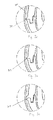
- FIGS. 3a-3e show a section from the cross section of FIG. 2 about the left seam 29 for various embodiments.
- FIG. 3a initially shows a small part of the magnesium profile 22 from right to left.
- the decorative layer 26 and on the half-shell 25, the wood veneer 27 is located on the half-shell 24, the decorative layer 26 and on the half-shell 25, the wood veneer 27 is located.
- the two decorative layers 26, 27 is formed of the two half-shells 24, 25 formed projection 31.
- the projection 31 is divided by the seam 29 in an upper part and a lower part.
- the lacquer layer 28 is applied.
- the projection 31 is formed differently than in Figure 3a. It is wider in the base than at the lacquer layer 28 side facing.
- FIG. 3 c shows a further modification of the projection 31, which is also stronger on the base than on the side facing the lacquer layer 28. On its side facing the lacquer layer 28, however, it is substantially linear.
- FIG. 3d shows a modification of the projection 31, in which the flanks of the projection are rounded.
- the decorative layer can adapt so well to the shape of the projection 31.
- FIG. 3 e shows a further alternative geometry with a projection 31.
- Figure 4 shows a cross section through a steering wheel rim according to the invention. Unlike in Figure 2, two half-shells are not connected by a smooth seam (29 in Figure 2), but by means of a groove 40 and a spring 41 with each other. There are no further deviations compared to FIG. 2.
- FIGS. 5a-5c each show a section of the cross section from FIG. 4 about the left-hand tongue-and-groove combination 40, 41. Just as in FIGS. 3a-3e, there are, of course, various possibilities for forming a projection 31.
- FIG. 6 shows a further cross section through the steering wheel rim according to the invention.
- New reference numbers are only introduced insofar as deviations from the previously presented arise.
- the core 21, 22, 23 is no longer surrounded by a two-part shell (as in FIG. 2 and in FIG. 4), but by a one-part so-called full shell 60.
- the decorative layer has two seams 61.
- FIG. 7 shows a section from the cross section from FIG. 6 about the left of the seams 61.
- a projection 31 projects out of the solid shell 60, so that here too the decorative layers 26, 27 do not abut one another.
- such an embodiment also allows numerous configurations of the projection 31.
- FIG. 8 shows a device for applying a decorative layer 83, here a wood veneer, to a half-shell 85 for a steering wheel rim body.
- a decorative layer 83 here a wood veneer
- the decorative layer 83 together with a dry adhesive film 84 (in this case a synthetic resin) is pressed onto the half shell 85 with a mold 81.
- the half shell 85 is supported by a counter-mold 82.
- a stack of a plurality of decorative layers, such as wood veneers with transverse grain directions, with intermediate adhesive films are applied to a steering wheel rim body.
- FIG. 9 shows a detail of the device of FIG. 8 during unwinding.
- the mold 81 cuts through the decorative layer 83 or the dry adhesive film 84 at its edge 86 so that the part of the decorative layer 83 projecting beyond the projection and the dry adhesive film 84 are severed. Otherwise, the mold 81 presses the decorative layer 83 and the dry adhesive film 84 onto the half-shell 85.
Landscapes
- Engineering & Computer Science (AREA)
- Mechanical Engineering (AREA)
- Life Sciences & Earth Sciences (AREA)
- Chemical & Material Sciences (AREA)
- Combustion & Propulsion (AREA)
- Transportation (AREA)
- Manufacturing & Machinery (AREA)
- Wood Science & Technology (AREA)
- Forests & Forestry (AREA)
- Steering Controls (AREA)
- Vehicle Interior And Exterior Ornaments, Soundproofing, And Insulation (AREA)
- Laminated Bodies (AREA)
Abstract
Description
- Die vorliegende Erfindung bezieht sich auf ein Auskleidungsteil mit einer Dekorlage, ein Lenkrad mit einem solchen Auskleidungsteil und ein Herstellungsverfahren für einen solches Auskleidungsteil.
- Auskleidungsteile mit einer Dekorlage sind an sich bekannt. Sie finden insbesondere bei der Inneneinrichtung von Kraftfahrzeugen Anwendung. Typische entsprechende Auskleidungsteile sind etwa: der Schalthebel, der Knauf auf dem Schalthebel, die Griffe zum Zuziehen der Türen, der Griff zum Zuziehen des Schiebedaches und Teile des Lenkrades, insbesondere der Lenkradkranz, womit der außen umlaufende Ring zur Handhabung des Lenkrades gemeint ist.
- All diese Auskleidungsteile weisen ein Inneres, einen "Körper", auf, auf welchem die Dekorlage aufgebracht ist. Üblicherweise wird auf die Dekorlage schließlich noch eine Lackschicht aufgetragen.
- Oft umfasst die Dekorlage das Auskleidungsteil. "Umfassen" ist hier so zu verstehen, dass sich die Dekorlage entlang eines Umfangs des Körpers über den wesentlichen Teil dieses Umfangs erstreckt. Der entsprechende Umfang des Körpers muss nicht unbedingt (kreis-)rund sein. Die Dekorlage kann etwa auch einen mehreckigen Körper, wie etwa einen Quader, umfassen. Auch kann der Krümmungsradius entlang des Umfangs veränderlich sein. Weiter muss auch kein Krümmungsmittelpunkt vorhanden sein.
- Der vorliegenden Erfindung liegt das technische Problem zugrunde, ein bzgl. seiner Dekorlage verbessertes Auskleidungsteil anzugeben.
- Die Erfindung bezieht sich auf ein Auskleidungsteil mit einem Körper und einer den Körper umfassenden Dekorlage, wobei die Dekorlage zwei Kanten aufweist und die beiden Kanten über ihre Fläche voneinander beabstandet sind, dadurch gekennzeichnet, dass in dem Abstand ein aus dem Körper hervortretender Vorsprung vorgesehen ist.
- Weiter bezieht sich die Erfindung auf ein Lenkrad, bei dem der Lenkradkranz ein erfindungsgemäßes Auskleidungsteil ist, und ein Verfahren zur Herstellung eines erfindungsgemäßen Auskleidungsteils.
- Bevorzugte Ausgestaltungen der Erfindung sind in den abhängigen Ansprüchen angegeben und werden im Folgenden näher erläutert. Die Offenbarung bezieht sich dabei stets sowohl auf das Auskleidungsteil und das Lenkrad als auch auf das Herstellungsverfahren für das Auskleidungsteil.
- Der Erfindung liegt die Tatsache zugrunde, dass Auskleidungsteile mit einer den jeweiligen Körper umfassenden Dekorlage oft produktionsbedingt eine Naht bzw. mehrere Nähte in der Dekorlage aufweisen. Üblicherweise stößt in diesen Nähten Dekorlage flächig an Dekorlage; flächig deswegen, weil die Dekorlage eine gewisse Stärke hat und nicht lediglich zweidimensional ist. Als Dekorlagen kommen beispielsweise Holz, Metalle, Kohlefasergewebe und Textilien infrage, also sowohl Kunst- als auch Naturstoffe.
- Die Erfindung basiert auf der Beobachtung, dass solche Nahtstellen problematisch sein können. Eine perfekt lückenfreie Naht zwischen den Dekorlagen ist technisch anspruchsvoll herzustellen. Ist der Zuschnitt allerdings nicht perfekt, so können Verunreinigungen oder Feuchtigkeit in die Naht eindringen und die Naht qualitativ weiter verschlechtern.
- Besonders problematisch ist dies im Fall von Holz-Holz-Nahtstellen. Holz verändert im Laufe der Zeit und in Abhängigkeit von Umwelteinflüssen sein Volumen, es arbeitet. Ggf. schließt dann die Naht auch bei einem ursprünglich perfekten Zuschnitt nicht mehr an allen Stellen und es kann Feuchtigkeit in die Naht eindringen, was zu einem Quellen des Holzfurnieres führen kann. Üblicherweise sind jedoch gerade Holz-Holz-Nahtstellen nicht perfekt verarbeitet, da dies besonders anspruchsvoll ist. Eine nicht lückenlos geschlossene Naht kann sich auch negativ auf die Optik eines Auskleidungsteiles auswirken.
- Die Erfindung basiert auf der Idee, zwischen den Kanten der Dekorlage einen aus dem Körper heraustretenden Vorsprung vorzusehen, so dass in der Naht nicht mehr Dekorlage flächig an Dekorlage stößt. Die Kanten der Dekorlage grenzen nun an den Vorsprung. Eine direkte Dekorlage-Dekorlage-Nahtstelle wird so vermieden. Ein solcher Übergang kann besonders sauber und effizient, etwa durch sog. Abzwicken hergestellt werden (siehe Herstellungsverfahren unten).
- Der Vorsprung kann den gesamten Raum zwischen den Kanten der Dekorlage ausfüllen. Sinnvollerweise weist ein erfindungsgemäßer Vorsprung die gleiche Stärke wie die Dekorlage an ihren Kanten auf und reicht von der Körperoberfläche bis zu den Außenseiten der angrenzenden Dekorlage.
- Der Vorsprung geht dabei übergangslos aus dem Material des Körpers hervor. Diese Einteiligkeit ist im Rahmen des erfindungsgemäßen Herstellungsverfahrens besonders vorteilhaft (s. u.). Beispielsweise können der Vorsprung und der Körper jeweils aus einem Thermoplast bestehen und miteinander verschweißt sein. Besonders vorteilhaft ist es jedoch, wenn der Körper direkt mit dem Vorsprung durch entsprechende Formgebung hergestellt wird, etwa mit Hilfe eines Gießverfahrens.
- Wie oben bereits kurz dargestellt sind gerade Holz-Holz-Nahtstellen besonders empfindlich. Weiter ist Holz als Naturstoff auch in der Verarbeitung besonders anspruchsvoll. Beispielsweise ist es sehr schwierig, durch Fräsen eine perfekt schließende Holznaht für ein rundes Auskleidungsteil herzustellen. Die Erfindung ist gerade im Fall eines Holzfurnieres als Dekorlage besonders vorteilhaft, da sich das Holzfurnier beim direkten Abzwicken an dem Vorsprung dicht schließend an diesen anlegen kann.
- Bei einer bevorzugten Ausführungsform der Erfindung ist der Vorsprung an der Oberfläche der Dekorlage relativ schmal ausgebildet; seine Breite nimmt jedoch in Richtung des Körpers zu. So ist einerseits eine gewisse mechanische Stabilität gewährleistet, was sich etwa positiv auf die Handhabbarkeit in der Produktion auswirkt, und andererseits an der sichtbaren Oberfläche der Dekorlage kaum etwas von dem Vorsprung zu sehen. Im Extremfall kann diese Ausführungsform so ausgeführt sein, dass der Vorsprung nur bis direkt an die Oberfläche reicht und die Oberfläche selbst dabei optisch geschlossen erscheint.
- Lenkräder, welche einen Lenkradkranz mit einer Dekorlage, insbesondere einem Holzfurnier, aufweisen, sind recht beliebt. Bei einer bevorzugten Ausgestaltung der Erfindung ist das Auskleidungsteil ein Lenkradkranz und der Körper, auf den die Dekorlage aufgebracht ist, der Lenkradkranzkörper. Die beiden Kanten der Dekorlage verlaufen dabei entlang des großen Umfangs des Lenkradkranzes. (Die Begriffe "großer Umfang" und "kleiner Umfang" sind hier nicht streng im mathematischen Sinn zu verstehen. So werden diese etwa auch verwendet, wenn der Lenkradkranzkörper entlang des benannten Umfangs nicht geschlossen ist, etwa weil in dem konkreten Kontext nur ein Lenkradkranzkörperteil betrachtet wird.)
- Es ist vorteilhaft, den Körper eines erfindungsgemäßen Auskleidungsteils nicht massiv auszuführen, sondern als eine Schale. Innerhalb der Schale kann dann ein einfacher oder komplexer Kern untergebracht werden, welcher auch durch eine Kombination mehrerer Bestandteile aus unterschiedlichen Materialien in unterschiedlicher Formgebung die mechanischen Eigenschaften des Auskleidungsteils in einer an den Bedarf angepassten Weise mitbestimmen kann.
- Beispielsweise kann für einen Lenkradkranz der Kern etwa einen entlang des großen Umfangs umlaufenden Stahlstrang und ein ebenso umlaufendes Magnesiumprofil aufweisen. Restliches Volumen innerhalb der Schale kann dann etwa mit einem Polyurethanschaum ausgefüllt sein.
- Bei einer bevorzugten Ausführungsform der Erfindung weist der Körper zwei Vorsprünge auf. Die Dekorlage wird durch die Vorsprünge unterteilt. Für den Spezialfall eines Lenkradkranzes bietet es sich etwa an, die Vorsprünge entlang des großen Umfangs zu positionieren. Entsprechend verlaufen dann zwei Streifen der Dekorlage entlang des großen Umfangs des Lenkradkranzes. Eine solche Ausführungsform ist in der Produktion besonders vorteilhaft (s. u. und das Ausführungsbeispiel), da ein Wickeln der Dekorlage um das Auskleidungsteil entfallen kann.
- Es gibt Auskleidungsteile, bei denen der Körper mehrteilig, insbesondere zweiteilig, ausgeführt ist. Die Anzahl der Nähte an der Oberfläche des Körpers zwischen den Teilen des Körpers muss nicht identisch sein mit der Anzahl der Nähte in der Dekorlage. In jedem Fall können die Nähte an der Oberfläche des Körpers auf die Nähte in der Dekorlage des Auskleidungsteils ausgerichtet sein. Wie oben festgestellt, ist ein flächiges Verkleben von stirnseitigen Dekorlagenkanten an sich schon problematisch. Im Falle eines mehrteiligen Körpers umso mehr, als dass bei der Produktion nicht nur die Dekorlage verklebt werden muss, sondern auch noch der darunterliegende Körper. Je größer die Komplexität in der Produktion, umso schwerer ist es natürlich zu gewährleisten, Nahtstellen wirklich sauber zu schließen. Vorzugsweise wird der Vorsprung (oder einer der Vorsprünge) des Körpers daher durch die Naht oder eine der Nähte in dem Körper der Länge nach geteilt. In einer solchen Konfiguration ist die Herstellung eines Auskleidungsteils mit einem mehrteiligen Körper besonders vorteilhaft (s. u. und das zugehörige Ausführungsbeispiel), weil das Aufbringen der Dekorlage und das Zusammenfügen des Körpers entkoppelt sind.
- Zum Aufbringen einer Dekorlage auf ein rundes Auskleidungsteil wird vorzugsweise mit einer Form und einer Gegenform gearbeitet. Dazu wird eine Dekorlage mit der Form gegen den Körper gepresst. Der Körper wird dabei so von der Gegenform gestützt, dass ein hinreichend großer Druck erzielt werden kann. Vor dem Zusammenpressen wird üblicherweise ein Film aus einem Klebemittel zwischen der Dekorlage und dem Körper eingebracht. Dies kann etwa ein Kunstharzklebefilm sein. Eine weitere Möglichkeit ist es, die Dekorlage oder den Körper mit einem Kunstharz, etwa einem Epoxidharz, zu besprühen.
- Form, Gegenform und Vorsprung können so aufeinander abgestimmt werden, dass die Dekorlage durch Abscherung so durchtrennt wird (sog. Abzwicken), dass sie anschließend flächig mit dem Vorsprung des Körpers in Kontakt steht (ggf. ist der Kontakt nicht direkt, sondern wird über das Klebemittel vermittelt).
- Zum Abzwicken können die Form und der Vorsprung so aufeinander abgestimmt sein, dass die Form an dem Vorsprung vorbei gleitet und scherend den über den Vorsprung hervorstehenden Teil der Dekorlage abtrennt. Die Gegenform kann allerdings auch den Vorsprung umschließen und an der der Form zugewandten Seite eine scharfe Kante aufweisen, so dass Form und Gegenform im gemeinsamen Zusammenwirken den überschüssigen Teil der Dekorlage abtrennen.
- Da beim Abzwicken die Dekorlage direkt an dem Vorsprung abgetrennt wird, sind besonders saubere Nahtstellen realisierbar. Ein anspruchsvoller durchzuführendes Zuschneiden bzw. Fräsen der Dekorlage vor dem Aufbringen auf den Körper entfällt.
- Für das Verfahren ist es besonders vorteilhaft, wenn der Körper zwei Vorsprünge aufweist (wie oben zu einer der bevorzugten Ausführungsformen dargestellt). Bei einem solchen Körper können nämlich durch die Vorsprünge abgetrennte Teile der Oberfläche jeweils wie eben beschrieben mit einer Dekorlage versehen werden. Ein weiterer Verfahrensschritt, wie etwa ein Herumführen der Dekorlage um das Auskleidungsteil herum, kann dann entfallen.
- Für einen Lenkradkranzkörper würde es sich beispielsweise anbieten, zwei sich diametral an dem Lenkradkranzkörper gegenüber liegende Vorsprünge entlang des großen Umfangs vorzusehen. Ein solcher Lenkradkranzkörper kann wie oben beschrieben mit zwei streifenförmigen Dekorlagen versehen werden. Ein Herumwickeln der Dekorlage ist hier nicht notwendig.
- Bei einem zweiteiligen Körper, dessen Nähte durch die beiden Vorsprünge verlaufen, ist das Zusammensetzen des Körpers dann unabhängig von dem Aufbringen der Dekorlage. Es kann zuerst die Dekorlage auf die Teile des Körpers aufgebracht werden, bevor diese zusammengesetzt werden und gegebenenfalls noch ein Kern eingebracht wird. Man hat also zusätzliche Freiheiten bei der Herstellung.
- Im Folgenden soll die Erfindung anhand von Ausführungsbeispielen näher erläutert werden. Die dabei offenbarten Einzelmerkmale können auch in anderen Kombinationen erfindungswesentlich sein.
- Figur 1
- zeigt die fahrerseitige Draufsicht auf ein Lenkrad mit einem Lenkradkranz als erfindungsgemäßes Auskleidungsteil.
- Figur 2
- zeigt einen Querschnitt durch den Lenkradkranz des Lenkrades aus Figur 1.
- Figuren 3a - 3e
- zeigen einen Ausschnitt aus dem Querschnitt der Figur 2 für verschiedene Ausführungsformen der Erfindung.
- Figur 4
- zeigt wie Figur 2 einen Querschnitt durch einen Lenkradkranz, allerdings mit einem veränderten Lenkradkranzkörper.
- Figuren 5a - 5c
- zeigen Ausschnitte aus dem Querschnitt der Figur 4 für verschiedene Ausführungsformen der Erfindung.
- Figur 6
- zeigt einen weiteren Querschnitt durch einen erfindungsgemäßen Lenkradkranzkörper.
- Figur 7
- zeigt einen Ausschnitt aus dem Querschnitt aus Figur 6.
- Figur 8
- zeigt eine Vorrichtung, die bei der erfindungsgemäßen Herstellung verwendet wird.
- Figur 9
- zeigt einen Ausschnitt aus der Vorrichtung aus Figur 8.
- Figur 1 zeigt ein Lenkrad 1 von der einem Fahrer zugewandten Seite aus. Das Lenkrad 1 weist einen außen umlaufenden, einem erfindungsgemäßen Auskleidungsteil entsprechenden Lenkradkranz 2 auf. In dem Lenkradkranz 2 ist eine Querschnittsfläche A-A markiert.
- Figur 2 zeigt den Querschnitt entlang der Querschnittsfläche A-A. Dieser Querschnitt veranschaulicht einen üblichen Aufbau eines Lenkradkranzes. In das Innere sind ein Stahlband 21, ein Magnesiumprofil 22 und Polyurethanschaum 23 eingebracht. Die Kombination dieser Bestandteile bestimmt wesentlich die mechanischen Eigenschaften des fertigen Lenkradkranzes. Das Stahlband 21 zusammen mit dem Magnesiumprofil 22 und dem Polyurethanschaum 23 werden als Kern des Lenkradkranzes bezeichnet. Der Kern 21, 22, 23 ist durch zwei Halbschalen 24, 25 aus Kunststoff (hier Polyamid) eingefasst. Die zwei Halbschalen 24, 25 stoßen an Nahtstellen 29 aneinander.
- Auf die beiden Halbschalen 24, 25 ist eine Dekorlage, hier ein Holzfurnier 26, 27, aufgebracht. Abschließend ist eine Lackschicht 28 aufgetragen. Auch die beiden Halbschalen 24, 25 und die Holzfurniere 26, 27 werden durch die Nahtstellen 29 voneinander getrennt.
- Die Figuren 3a - 3e zeigen einen Ausschnitt aus dem Querschnitt der Figur 2 um die linke Naht 29 für verschiedene Ausführungsformen.
- Figur 3a zeigt von rechts nach links zunächst noch einen kleinen Teil des Magnesiumprofils 22. Es folgen das Polyurethan 23 und die beiden Halbschalen 24, 25, welche in der Naht 29 aufeinander stoßen. Auf der Halbschale 24 liegt die Dekorlage 26 und auf der Halbschale 25 das Holzfurnier 27 auf. Zwischen den beiden Dekorlagen 26, 27 liegt ein aus den beiden Halbschalen 24, 25 ausgebildeter Vorsprung 31. Der Vorsprung 31 ist durch die Naht 29 in einen oberen Teil und einen unteren Teil geteilt. Auf die beiden Dekorlagen 26, 27 und den Vorsprung 31 ist die Lackschicht 28 aufgebracht.
- Der Übersichtlichkeit halber werden die bisher eingeführten Bezugszeichen für entsprechende Merkmale weiter verwendet, auch wenn diese an sich anders ausgebildet sind oder zu einer anderen Ausführungsform gehören.
- In Figur 3b ist der Vorsprung 31 anders ausgebildet als in Figur 3a. Er ist in der Basis breiter als an der der Lackschicht 28 zugewandten Seite.
- Figur 3c zeigt eine weitere Abwandlung des Vorsprungs 31, welcher auch an der Basis stärker ausgebildet ist als an der der Lackschicht 28 zugewandten Seite. An seiner der Lackschicht 28 zugewandten Seite ist er jedoch im Wesentlichen linienförmig.
- Figur 3d zeigt eine Abwandlung des Vorsprungs 31, bei dem die Flanken des Vorsprungs verrundet sind. In der Herstellung (beim Abzwicken, s. u.) kann die Dekorlage sich so besonders gut an die Form des Vorsprungs 31 anpassen.
- Figur 3e zeigte eine weitere alternative Geometrie mit einem Vorsprung 31.
- Wie Figur 2 zeigt Figur 4 einen Querschnitt durch einen erfindungsgemäßen Lenkradkranz. Anders als in Figur 2 sind zwei Halbschalen nicht durch eine glatte Naht (29 in Figur 2), sondern mittels einer Nut 40 und einer Feder 41 miteinander verbunden. Es liegen keine weiteren Abweichungen im Vergleich zu Figur 2 vor.
- Figuren 5a - 5c zeigen jeweils einen Ausschnitt des Querschnitts aus Figur 4 um die linke Nut-und-Feder-Kombination 40, 41. Genau wie in den Figuren 3a - 3e gibt es natürlich verschiedene Möglichkeiten einen Vorsprung 31 auszubilden.
- Figur 6 zeigt einen weiteren Querschnitt durch den erfindungsgemäßen Lenkradkranz. Neue Bezugszeichen sind nur eingeführt, soweit sich Abweichungen gegenüber dem zuvor Vorgestellten ergeben. Der Kern 21, 22, 23 ist nun nicht mehr von einer zweiteiligen Schale (wie in Figur 2 und in Figur 4) umgeben, sondern von einer einteiligen sog. Vollschale 60. Auch hier weist die Dekorlage zwei Nahtstellen 61 auf.
- Figur 7 zeigt einen Ausschnitt aus dem Querschnitt aus Figur 6 um die linke der Nahtstellen 61. Ein Vorsprung 31 ragt aus der Vollschale 60 heraus, so dass auch hier die Dekorlagen 26, 27 nicht aneinander stoßen. Natürlich erlaubt auch eine solche Ausführungsform zahlreiche Gestaltungen des Vorsprungs 31.
- Figur 8 zeigt eine Vorrichtung zum Aufbringen einer Dekorlage 83, hier einem Holzfurnier, auf eine Halbschale 85 für einen Lenkradkranzkörper. Dazu wird mit einer Form 81 die Dekorlage 83 zusammen mit einem Trockenklebefilm 84 (hier einem Kunstharz) auf die Halbschale 85 aufgepresst. Die Halbschale 85 wird von einer Gegenform 82 gestützt. Beim Anpressen der Dekorlage 83 an die Halbschale 85 wird die Dekorlage 83 durch Kanten 86 der Form 81 abgetrennt (Abzwicken).
- Auf diese Weise kann auch ein Stapel aus mehreren Dekorlagen, etwa Holzfurnieren mit quer zueinander liegenden Faserrichtungen, mit dazwischen liegenden Klebefilmen auf einen Lenkradkranzkörper aufgebracht werden.
- Figur 9 zeigt ein Detail der Vorrichtung aus Figur 8 während des Abzwickens. Die Form 81 durchtrennt die Dekorlage 83 bzw. den Trockenklebfilm 84 an ihrer Kante 86 so, dass der über den Vorsprung hinaus ragende Teil der Dekorlage 83 und des Trockenklebefilms 84 abgetrennt werden. Ansonsten presst die Form 81 die Dekorlage 83 und den Trockenklebefilm 84 auf die Halbschale 85.
Claims (11)
- Auskleidungsteil (2) mit einem Körper (24, 25, 60, 85) und einer den Körper (24, 25, 60, 85) umfassenden Dekorlage (26, 27, 83), wobei die Dekorlage (26, 27, 83) zwei Kanten aufweist und die beiden Kanten über ihre Fläche voneinander beabstandet sind,
dadurch gekennzeichnet, dass in dem Abstand ein aus dem Körper (24, 25, 60, 85) hervortretender Vorsprung (31) vorgesehen ist. - Auskleidungsteil (2) nach Anspruch 1, bei dem die Dekorlage (26, 27, 83) ein Holzfurnier (83) ist.
- Auskleidungsteil (2) nach einem der vorangehenden Ansprüche, bei dem das der Oberfläche des Auskleidungsteils (2) zugewandte Ende des Vorsprungs (31) schmaler ist als das dem Körper (24, 25, 60, 85) zugewandte Ende.
- Auskleidungsteil (2) nach einem der vorangehenden Ansprüche, welches als Lenkradkranz (2) ausgelegt ist, der Körper (24, 25, 60, 83) ein Lenkradkranzkörper (24, 25, 60, 85) ist und bei dem die zwei Kanten entlang des großen Umfangs des Lenkradkranzes (2) verlaufen.
- Auskleidungsteil nach einem der vorangehenden Ansprüche, bei dem der Körper (24, 25, 60, 85) eine Schale (24, 25, 60, 85) ist und einen inneren Kern (21, 22, 23) umschließt.
- Auskleidungsteil nach einem der vorangehenden Ansprüche, bei dem die Dekorlage (26, 27, 83) vier Kanten aufweist und jeweils zwei der Kanten über ihre Stärke flächig voneinander beabstandet sind und in beiden Abständen jeweils ein Vorsprung (31) des Körpers (24, 25, 60, 85) vorgesehen ist.
- Auskleidungsteil nach einem der vorangehenden Ansprüche, bei dem der Körper (24, 25, 85) mehrteilig ausgeführt ist und eine Naht (29) zwischen den Teilen durch den Vorsprung des Körpers (24, 25, 85) verläuft.
- Lenkrad (1) mit einem Auskleidungsteil (2) nach Anspruch 4, auch in Kombination mit einem weiteren der vorangehenden Ansprüche.
- Verfahren zur Herstellung eines Auskleidungsteils (2) mit den Schritten:Aufbringen einer Dekorlage (26, 27, 83) auf einen Körper (24, 25, 60, 85), so dass die Dekorlage (26, 27, 83) den Körper umfasst, wobei die Dekorlage (26, 27, 83) zwei Kanten aufweist, welche über ihre Stärke flächig voneinander beabstandet sind,
gekennzeichnet durch den weiteren Schritt:Einbringen eines aus dem Körper (24, 25, 60, 85) hervortretenden Vorsprungs (31) in den Abstand zwischen den beiden Kanten. - Verfahren nach Anspruch 9 mit den weiteren Schritten:Aufbringen der Dekorlage (26, 27, 83) auf den Körper (24, 25, 60, 85) durch Anpressen mit einer Form und einer Gegenform undAbzwicken der Dekorlage (26, 27, 83) an dem zu dem Körper (24, 25, 60, 85) distalen Ende des hervortretenden Vorsprunges (31).
- Verfahren nach Anspruch 10, bei dem der Körper (24, 25, 60, 85) zwei aus dem Körper (24, 25, 60, 85) hervortretende Vorsprünge (31) aufweist und die Dekorlage (26, 27, 83) jeweils an dem zu dem Körper (24, 25, 60, 85) distalen Ende der Vorsprünge (31) abgezwickt wird.
Priority Applications (3)
| Application Number | Priority Date | Filing Date | Title |
|---|---|---|---|
| AT06117913T ATE408548T1 (de) | 2006-07-26 | 2006-07-26 | Herstellungsverfahren für auskleidungsteile mit dekorlage |
| EP06117913A EP1884442B1 (de) | 2006-07-26 | 2006-07-26 | Herstellungsverfahren für Auskleidungsteile mit Dekorlage |
| DE502006001612T DE502006001612D1 (de) | 2006-07-26 | 2006-07-26 | Herstellungsverfahren für Auskleidungsteile mit Dekorlage |
Applications Claiming Priority (1)
| Application Number | Priority Date | Filing Date | Title |
|---|---|---|---|
| EP06117913A EP1884442B1 (de) | 2006-07-26 | 2006-07-26 | Herstellungsverfahren für Auskleidungsteile mit Dekorlage |
Publications (2)
| Publication Number | Publication Date |
|---|---|
| EP1884442A1 true EP1884442A1 (de) | 2008-02-06 |
| EP1884442B1 EP1884442B1 (de) | 2008-09-17 |
Family
ID=37137358
Family Applications (1)
| Application Number | Title | Priority Date | Filing Date |
|---|---|---|---|
| EP06117913A Not-in-force EP1884442B1 (de) | 2006-07-26 | 2006-07-26 | Herstellungsverfahren für Auskleidungsteile mit Dekorlage |
Country Status (3)
| Country | Link |
|---|---|
| EP (1) | EP1884442B1 (de) |
| AT (1) | ATE408548T1 (de) |
| DE (1) | DE502006001612D1 (de) |
Cited By (2)
| Publication number | Priority date | Publication date | Assignee | Title |
|---|---|---|---|---|
| EP2439056A1 (de) * | 2010-10-09 | 2012-04-11 | Quin GmbH | Verfahren zur Herstellung eines Dekorteiles und ein solches Dekorteil |
| WO2014072155A1 (de) | 2012-11-07 | 2014-05-15 | Bayerische Motoren Werke Aktiengesellschaft | Fahrzeug-lenkrad aus faserverstärktem kunststoff |
Citations (4)
| Publication number | Priority date | Publication date | Assignee | Title |
|---|---|---|---|---|
| DE1555182A1 (de) * | 1966-12-20 | 1970-08-13 | Daimler Benz Ag | Elastisch nachgiebiger Lenkradbezug |
| EP1069023A1 (de) * | 1999-07-13 | 2001-01-17 | Gersteen - Iso Delta | Kraftfahrzeuglenkrad |
| EP1095840A1 (de) * | 1999-10-27 | 2001-05-02 | Autoliv-Isodelta | Kraftfahrzeuglenkrad und Verfahren zu seiner Herstellung |
| EP1442957A1 (de) * | 2003-01-30 | 2004-08-04 | Breed Automotive Technology, Inc. | Lenkrad mit thermoplastischen Verbundmaterialien |
-
2006
- 2006-07-26 EP EP06117913A patent/EP1884442B1/de not_active Not-in-force
- 2006-07-26 DE DE502006001612T patent/DE502006001612D1/de active Active
- 2006-07-26 AT AT06117913T patent/ATE408548T1/de not_active IP Right Cessation
Patent Citations (4)
| Publication number | Priority date | Publication date | Assignee | Title |
|---|---|---|---|---|
| DE1555182A1 (de) * | 1966-12-20 | 1970-08-13 | Daimler Benz Ag | Elastisch nachgiebiger Lenkradbezug |
| EP1069023A1 (de) * | 1999-07-13 | 2001-01-17 | Gersteen - Iso Delta | Kraftfahrzeuglenkrad |
| EP1095840A1 (de) * | 1999-10-27 | 2001-05-02 | Autoliv-Isodelta | Kraftfahrzeuglenkrad und Verfahren zu seiner Herstellung |
| EP1442957A1 (de) * | 2003-01-30 | 2004-08-04 | Breed Automotive Technology, Inc. | Lenkrad mit thermoplastischen Verbundmaterialien |
Cited By (7)
| Publication number | Priority date | Publication date | Assignee | Title |
|---|---|---|---|---|
| EP2439056A1 (de) * | 2010-10-09 | 2012-04-11 | Quin GmbH | Verfahren zur Herstellung eines Dekorteiles und ein solches Dekorteil |
| WO2012045476A1 (de) * | 2010-10-09 | 2012-04-12 | Quin Gmbh | Verfahren zur herstellung eines dekorteiles und ein solches dekorteil |
| CN103153588A (zh) * | 2010-10-09 | 2013-06-12 | 奎因有限公司 | 用于制造装饰部的方法及这种装饰部 |
| CN103153588B (zh) * | 2010-10-09 | 2015-04-29 | 奎因有限公司 | 用于制造装饰部的方法及这种装饰部 |
| US9272467B2 (en) | 2010-10-09 | 2016-03-01 | Quin Gmbh | Method for producing a decorative part, and such a decorative part |
| WO2014072155A1 (de) | 2012-11-07 | 2014-05-15 | Bayerische Motoren Werke Aktiengesellschaft | Fahrzeug-lenkrad aus faserverstärktem kunststoff |
| DE102012220288A1 (de) | 2012-11-07 | 2014-06-12 | Bayerische Motoren Werke Aktiengesellschaft | Fahrzeug-Lenkrad aus faserverstärktem Kunststoff |
Also Published As
| Publication number | Publication date |
|---|---|
| ATE408548T1 (de) | 2008-10-15 |
| EP1884442B1 (de) | 2008-09-17 |
| DE502006001612D1 (de) | 2008-10-30 |
Similar Documents
| Publication | Publication Date | Title |
|---|---|---|
| DE10210517B3 (de) | Verfahren zur Herstellung eines Bauteiles in Faserverbundbauweise | |
| DE60319336T2 (de) | Lenkrad mit thermoplastischen Verbundmaterialien | |
| DE19528788C1 (de) | Verfahren zum Herstellen eines Lenkrades für Fahrzeuge mit einer Auflage aus einem Naturprodukt | |
| DE102011086701B4 (de) | Mittelkonsole für Fahrzeuge sowie Verfahren zu deren Herstellung | |
| DE10152365B4 (de) | Lenkrad und Verfahren zur Herstellung eines Lenkrads | |
| DE102011003222A1 (de) | Betätigungspedal für Kraftfahrzeuge | |
| EP3446848B1 (de) | Dämmelement sowie verfahren zur herstellung eines solchen | |
| WO2016041555A2 (de) | Spindel für einen kugelgewindetrieb und verfahren zur herstellung derselben | |
| AT504882B1 (de) | Verfahren zur herstellung von lenkrädern für kraftfahrzeuge | |
| DE2417491C3 (de) | Randbefestigung eines Klebehimmels für die Innenverkleidung des Fahrzeugdaches von Kraftfahrzeugen und Verfahren zu deren Herstellung | |
| EP1884442B1 (de) | Herstellungsverfahren für Auskleidungsteile mit Dekorlage | |
| EP2457808B1 (de) | Verfahren zur herstellung einer seitenwand | |
| EP3446843B1 (de) | Freiform-holzprofil und dessen herstellung | |
| DE102007057637A1 (de) | Verfahren zum Beledern eines Fahrzeuginnenraumteiles, insbesondere eines Fahrzeuglenkrades | |
| DE10312465A1 (de) | Verfahren zur Herstellung eines Fahrzeug-Karosserieteils | |
| DE102010029724B4 (de) | Verfahren zum Herstellen eines Interieurbauteils und modulares System für die Herstellung des Interieurbauteils, sowie Verwendung des modularen Systems in dem Verfahren und Verwendung einer Adapterschicht zum Ausgleichen unterschiedlicher Materialstärken von Dekorschichten bei der Herstellung des Interieurbauteils | |
| EP1584452B1 (de) | Verfahren zum Herstellen eines formstabilen, hohlkörperförmigen Elementes mit einem Bodenbereich und Verwendung eines solchen Elementes | |
| EP2744639A2 (de) | Verfahren und vorrichtung zum partiellen kaschieren eines bauteiles, insbesondere eines fahrzeugteiles | |
| DE19833314C2 (de) | Verfahren zum Herstellen eines Lenkrades | |
| DE102007010769A1 (de) | Felge sowie Verfahren zum Herstellen einer Felge | |
| DE202006011659U1 (de) | Auskleidungsteile mit Dekorlage | |
| DE102015001944A1 (de) | Vakuum-Bremskraftverstärker mit versteiftem Gehäuse | |
| EP1591318B1 (de) | Verfahren zum Herstellen eines Innenverkleidungsteils und Innenverkleidungsteil | |
| DE10120203A1 (de) | Rad | |
| DE202013104000U1 (de) | Griffvorrichtung für ein Fahrzeug |
Legal Events
| Date | Code | Title | Description |
|---|---|---|---|
| PUAI | Public reference made under article 153(3) epc to a published international application that has entered the european phase |
Free format text: ORIGINAL CODE: 0009012 |
|
| GRAP | Despatch of communication of intention to grant a patent |
Free format text: ORIGINAL CODE: EPIDOSNIGR1 |
|
| 17P | Request for examination filed |
Effective date: 20070507 |
|
| AK | Designated contracting states |
Kind code of ref document: A1 Designated state(s): AT BE BG CH CY CZ DE DK EE ES FI FR GB GR HU IE IS IT LI LT LU LV MC NL PL PT RO SE SI SK TR |
|
| AX | Request for extension of the european patent |
Extension state: AL BA HR MK YU |
|
| GRAS | Grant fee paid |
Free format text: ORIGINAL CODE: EPIDOSNIGR3 |
|
| GRAA | (expected) grant |
Free format text: ORIGINAL CODE: 0009210 |
|
| AK | Designated contracting states |
Kind code of ref document: B1 Designated state(s): AT BE BG CH CY CZ DE DK EE ES FI FR GB GR HU IE IS IT LI LT LU LV MC NL PL PT RO SE SI SK TR |
|
| REG | Reference to a national code |
Ref country code: GB Ref legal event code: FG4D Free format text: NOT ENGLISH |
|
| REG | Reference to a national code |
Ref country code: CH Ref legal event code: EP |
|
| AKX | Designation fees paid |
Designated state(s): AT BE BG CH CY CZ DE DK EE ES FI FR GB GR HU IE IS IT LI LT LU LV MC NL PL PT RO SE SI SK TR |
|
| REG | Reference to a national code |
Ref country code: IE Ref legal event code: FG4D Free format text: LANGUAGE OF EP DOCUMENT: GERMAN |
|
| REF | Corresponds to: |
Ref document number: 502006001612 Country of ref document: DE Date of ref document: 20081030 Kind code of ref document: P |
|
| PG25 | Lapsed in a contracting state [announced via postgrant information from national office to epo] |
Ref country code: LT Free format text: LAPSE BECAUSE OF FAILURE TO SUBMIT A TRANSLATION OF THE DESCRIPTION OR TO PAY THE FEE WITHIN THE PRESCRIBED TIME-LIMIT Effective date: 20080917 |
|
| PG25 | Lapsed in a contracting state [announced via postgrant information from national office to epo] |
Ref country code: LV Free format text: LAPSE BECAUSE OF FAILURE TO SUBMIT A TRANSLATION OF THE DESCRIPTION OR TO PAY THE FEE WITHIN THE PRESCRIBED TIME-LIMIT Effective date: 20080917 Ref country code: SI Free format text: LAPSE BECAUSE OF FAILURE TO SUBMIT A TRANSLATION OF THE DESCRIPTION OR TO PAY THE FEE WITHIN THE PRESCRIBED TIME-LIMIT Effective date: 20080917 Ref country code: FI Free format text: LAPSE BECAUSE OF FAILURE TO SUBMIT A TRANSLATION OF THE DESCRIPTION OR TO PAY THE FEE WITHIN THE PRESCRIBED TIME-LIMIT Effective date: 20080917 |
|
| NLV1 | Nl: lapsed or annulled due to failure to fulfill the requirements of art. 29p and 29m of the patents act | ||
| REG | Reference to a national code |
Ref country code: IE Ref legal event code: FD4D |
|
| PG25 | Lapsed in a contracting state [announced via postgrant information from national office to epo] |
Ref country code: BG Free format text: LAPSE BECAUSE OF FAILURE TO SUBMIT A TRANSLATION OF THE DESCRIPTION OR TO PAY THE FEE WITHIN THE PRESCRIBED TIME-LIMIT Effective date: 20081217 Ref country code: ES Free format text: LAPSE BECAUSE OF FAILURE TO SUBMIT A TRANSLATION OF THE DESCRIPTION OR TO PAY THE FEE WITHIN THE PRESCRIBED TIME-LIMIT Effective date: 20081228 |
|
| PG25 | Lapsed in a contracting state [announced via postgrant information from national office to epo] |
Ref country code: NL Free format text: LAPSE BECAUSE OF FAILURE TO SUBMIT A TRANSLATION OF THE DESCRIPTION OR TO PAY THE FEE WITHIN THE PRESCRIBED TIME-LIMIT Effective date: 20080917 Ref country code: IS Free format text: LAPSE BECAUSE OF FAILURE TO SUBMIT A TRANSLATION OF THE DESCRIPTION OR TO PAY THE FEE WITHIN THE PRESCRIBED TIME-LIMIT Effective date: 20090117 Ref country code: CZ Free format text: LAPSE BECAUSE OF FAILURE TO SUBMIT A TRANSLATION OF THE DESCRIPTION OR TO PAY THE FEE WITHIN THE PRESCRIBED TIME-LIMIT Effective date: 20080917 Ref country code: SK Free format text: LAPSE BECAUSE OF FAILURE TO SUBMIT A TRANSLATION OF THE DESCRIPTION OR TO PAY THE FEE WITHIN THE PRESCRIBED TIME-LIMIT Effective date: 20080917 Ref country code: RO Free format text: LAPSE BECAUSE OF FAILURE TO SUBMIT A TRANSLATION OF THE DESCRIPTION OR TO PAY THE FEE WITHIN THE PRESCRIBED TIME-LIMIT Effective date: 20080917 Ref country code: PT Free format text: LAPSE BECAUSE OF FAILURE TO SUBMIT A TRANSLATION OF THE DESCRIPTION OR TO PAY THE FEE WITHIN THE PRESCRIBED TIME-LIMIT Effective date: 20090217 |
|
| PLBE | No opposition filed within time limit |
Free format text: ORIGINAL CODE: 0009261 |
|
| STAA | Information on the status of an ep patent application or granted ep patent |
Free format text: STATUS: NO OPPOSITION FILED WITHIN TIME LIMIT |
|
| PG25 | Lapsed in a contracting state [announced via postgrant information from national office to epo] |
Ref country code: IE Free format text: LAPSE BECAUSE OF FAILURE TO SUBMIT A TRANSLATION OF THE DESCRIPTION OR TO PAY THE FEE WITHIN THE PRESCRIBED TIME-LIMIT Effective date: 20080917 Ref country code: DK Free format text: LAPSE BECAUSE OF FAILURE TO SUBMIT A TRANSLATION OF THE DESCRIPTION OR TO PAY THE FEE WITHIN THE PRESCRIBED TIME-LIMIT Effective date: 20080917 Ref country code: EE Free format text: LAPSE BECAUSE OF FAILURE TO SUBMIT A TRANSLATION OF THE DESCRIPTION OR TO PAY THE FEE WITHIN THE PRESCRIBED TIME-LIMIT Effective date: 20080917 |
|
| 26N | No opposition filed |
Effective date: 20090618 |
|
| PG25 | Lapsed in a contracting state [announced via postgrant information from national office to epo] |
Ref country code: SE Free format text: LAPSE BECAUSE OF FAILURE TO SUBMIT A TRANSLATION OF THE DESCRIPTION OR TO PAY THE FEE WITHIN THE PRESCRIBED TIME-LIMIT Effective date: 20081217 |
|
| BERE | Be: lapsed |
Owner name: NOVEM CAR INTERIOR DESIGN G.M.B.H. Effective date: 20090731 |
|
| PG25 | Lapsed in a contracting state [announced via postgrant information from national office to epo] |
Ref country code: MC Free format text: LAPSE BECAUSE OF NON-PAYMENT OF DUE FEES Effective date: 20090731 |
|
| PG25 | Lapsed in a contracting state [announced via postgrant information from national office to epo] |
Ref country code: PL Free format text: LAPSE BECAUSE OF FAILURE TO SUBMIT A TRANSLATION OF THE DESCRIPTION OR TO PAY THE FEE WITHIN THE PRESCRIBED TIME-LIMIT Effective date: 20080917 |
|
| PG25 | Lapsed in a contracting state [announced via postgrant information from national office to epo] |
Ref country code: BE Free format text: LAPSE BECAUSE OF NON-PAYMENT OF DUE FEES Effective date: 20090731 |
|
| PG25 | Lapsed in a contracting state [announced via postgrant information from national office to epo] |
Ref country code: GR Free format text: LAPSE BECAUSE OF FAILURE TO SUBMIT A TRANSLATION OF THE DESCRIPTION OR TO PAY THE FEE WITHIN THE PRESCRIBED TIME-LIMIT Effective date: 20081218 |
|
| PG25 | Lapsed in a contracting state [announced via postgrant information from national office to epo] |
Ref country code: AT Free format text: LAPSE BECAUSE OF NON-PAYMENT OF DUE FEES Effective date: 20090726 |
|
| REG | Reference to a national code |
Ref country code: CH Ref legal event code: PL |
|
| PG25 | Lapsed in a contracting state [announced via postgrant information from national office to epo] |
Ref country code: CH Free format text: LAPSE BECAUSE OF NON-PAYMENT OF DUE FEES Effective date: 20100731 Ref country code: LI Free format text: LAPSE BECAUSE OF NON-PAYMENT OF DUE FEES Effective date: 20100731 Ref country code: LU Free format text: LAPSE BECAUSE OF NON-PAYMENT OF DUE FEES Effective date: 20090726 |
|
| PG25 | Lapsed in a contracting state [announced via postgrant information from national office to epo] |
Ref country code: HU Free format text: LAPSE BECAUSE OF FAILURE TO SUBMIT A TRANSLATION OF THE DESCRIPTION OR TO PAY THE FEE WITHIN THE PRESCRIBED TIME-LIMIT Effective date: 20090318 |
|
| PG25 | Lapsed in a contracting state [announced via postgrant information from national office to epo] |
Ref country code: TR Free format text: LAPSE BECAUSE OF FAILURE TO SUBMIT A TRANSLATION OF THE DESCRIPTION OR TO PAY THE FEE WITHIN THE PRESCRIBED TIME-LIMIT Effective date: 20080917 |
|
| PG25 | Lapsed in a contracting state [announced via postgrant information from national office to epo] |
Ref country code: CY Free format text: LAPSE BECAUSE OF FAILURE TO SUBMIT A TRANSLATION OF THE DESCRIPTION OR TO PAY THE FEE WITHIN THE PRESCRIBED TIME-LIMIT Effective date: 20080917 |
|
| REG | Reference to a national code |
Ref country code: DE Ref legal event code: R082 Ref document number: 502006001612 Country of ref document: DE Representative=s name: SSP SCHIESSL RECHTSANWAELTE, DE Ref country code: DE Ref legal event code: R082 Ref document number: 502006001612 Country of ref document: DE Representative=s name: SMITH, GAMBRELL AND RUSSELL, LLP, DE |
|
| PGFP | Annual fee paid to national office [announced via postgrant information from national office to epo] |
Ref country code: FR Payment date: 20140721 Year of fee payment: 9 Ref country code: GB Payment date: 20140721 Year of fee payment: 9 |
|
| PGFP | Annual fee paid to national office [announced via postgrant information from national office to epo] |
Ref country code: IT Payment date: 20140728 Year of fee payment: 9 |
|
| GBPC | Gb: european patent ceased through non-payment of renewal fee |
Effective date: 20150726 |
|
| PG25 | Lapsed in a contracting state [announced via postgrant information from national office to epo] |
Ref country code: IT Free format text: LAPSE BECAUSE OF NON-PAYMENT OF DUE FEES Effective date: 20150726 Ref country code: GB Free format text: LAPSE BECAUSE OF NON-PAYMENT OF DUE FEES Effective date: 20150726 |
|
| REG | Reference to a national code |
Ref country code: FR Ref legal event code: ST Effective date: 20160331 |
|
| PG25 | Lapsed in a contracting state [announced via postgrant information from national office to epo] |
Ref country code: FR Free format text: LAPSE BECAUSE OF NON-PAYMENT OF DUE FEES Effective date: 20150731 |
|
| REG | Reference to a national code |
Ref country code: DE Ref legal event code: R082 Ref document number: 502006001612 Country of ref document: DE Representative=s name: MEISSNER BOLTE PATENTANWAELTE RECHTSANWAELTE P, DE |
|
| PGFP | Annual fee paid to national office [announced via postgrant information from national office to epo] |
Ref country code: DE Payment date: 20210729 Year of fee payment: 16 |
|
| REG | Reference to a national code |
Ref country code: DE Ref legal event code: R119 Ref document number: 502006001612 Country of ref document: DE |
|
| PG25 | Lapsed in a contracting state [announced via postgrant information from national office to epo] |
Ref country code: DE Free format text: LAPSE BECAUSE OF NON-PAYMENT OF DUE FEES Effective date: 20230201 |