EP1884258A1 - Dispositif d'introduction d'un cathéter intraveineux muni d'une chambre de retour - Google Patents
Dispositif d'introduction d'un cathéter intraveineux muni d'une chambre de retour Download PDFInfo
- Publication number
- EP1884258A1 EP1884258A1 EP06254061A EP06254061A EP1884258A1 EP 1884258 A1 EP1884258 A1 EP 1884258A1 EP 06254061 A EP06254061 A EP 06254061A EP 06254061 A EP06254061 A EP 06254061A EP 1884258 A1 EP1884258 A1 EP 1884258A1
- Authority
- EP
- European Patent Office
- Prior art keywords
- flashback
- introducing device
- needle
- intravenous catheter
- flashback chamber
- Prior art date
- Legal status (The legal status is an assumption and is not a legal conclusion. Google has not performed a legal analysis and makes no representation as to the accuracy of the status listed.)
- Withdrawn
Links
Images


Classifications
-
- A—HUMAN NECESSITIES
- A61—MEDICAL OR VETERINARY SCIENCE; HYGIENE
- A61M—DEVICES FOR INTRODUCING MEDIA INTO, OR ONTO, THE BODY; DEVICES FOR TRANSDUCING BODY MEDIA OR FOR TAKING MEDIA FROM THE BODY; DEVICES FOR PRODUCING OR ENDING SLEEP OR STUPOR
- A61M25/00—Catheters; Hollow probes
- A61M25/01—Introducing, guiding, advancing, emplacing or holding catheters
- A61M25/06—Body-piercing guide needles or the like
- A61M25/0606—"Over-the-needle" catheter assemblies, e.g. I.V. catheters
-
- A—HUMAN NECESSITIES
- A61—MEDICAL OR VETERINARY SCIENCE; HYGIENE
- A61M—DEVICES FOR INTRODUCING MEDIA INTO, OR ONTO, THE BODY; DEVICES FOR TRANSDUCING BODY MEDIA OR FOR TAKING MEDIA FROM THE BODY; DEVICES FOR PRODUCING OR ENDING SLEEP OR STUPOR
- A61M5/00—Devices for bringing media into the body in a subcutaneous, intra-vascular or intramuscular way; Accessories therefor, e.g. filling or cleaning devices, arm-rests
- A61M5/178—Syringes
- A61M5/31—Details
- A61M5/315—Pistons; Piston-rods; Guiding, blocking or restricting the movement of the rod or piston; Appliances on the rod for facilitating dosing ; Dosing mechanisms
- A61M5/31501—Means for blocking or restricting the movement of the rod or piston
- A61M2005/31508—Means for blocking or restricting the movement of the rod or piston provided on the piston-rod
-
- A—HUMAN NECESSITIES
- A61—MEDICAL OR VETERINARY SCIENCE; HYGIENE
- A61M—DEVICES FOR INTRODUCING MEDIA INTO, OR ONTO, THE BODY; DEVICES FOR TRANSDUCING BODY MEDIA OR FOR TAKING MEDIA FROM THE BODY; DEVICES FOR PRODUCING OR ENDING SLEEP OR STUPOR
- A61M25/00—Catheters; Hollow probes
- A61M25/01—Introducing, guiding, advancing, emplacing or holding catheters
- A61M25/06—Body-piercing guide needles or the like
- A61M25/0693—Flashback chambers
Definitions
- This invention relates to an intravenous catheter introducing device, more particularly to an intravenous catheter introducing device having a flashback member that can still be held in a ready position, without application of any manual force, once a needle cannula has pierced into a patient' s skin to locate a vein for taking a blood sample.
- Intravenous catheter inserting devices are generally used to administer medication fluids into or draw blood from a patient's vein.
- a conventional intravenous catheter inserting device 10 is shown to include a tubular needle seat 101 with a hub end 1011, a needle cannula 104 secured to the hub end 1011, a catheter hub 102 sleeved on the needle seat 1011, and a flexible tubular catheter 103 secured to the catheter hub 102.
- the catheter 103 and the needle cannula 104 are inserted into the patient' s vein by a health care worker by piercing the patient' s vein with a sharp tip of the needle cannula 104 which projects outwardly of the catheter 103.
- the health care worker then withdraws the needle cannula 104 from the catheter 103 with one hand and, at the same time, applies pressure to the patient's skin with the other hand, thereby leaving the catheter 103 in the patient's vein.
- a transfusion member (not shown) with a medication fluid or an empty barrel is connected to the catheter hub 102 for administering the medication fluid into the patient's vein or for drawing blood.
- the exposed sharp tip of the used needle cannula 104 may create a danger of an accidental needle stick.
- blood contamination may occur during connection of the catheter hub 103 to the transfusion member or the empty barrel.
- the flow of blood into the catheter 103 through a notch 105 in the needle cannula 104 can be observed through the translucent catheter 103.
- the needle cannula 104 tends to be bent during passage of the catheter 103 into the patient's vein.
- the blood in the catheter 103 is not visible when the portion of the needle cannula 104 with the notch 105 is inserted into the patient's vein.
- the conventional intravenous catheter inserting device 10 is specifically not suitable for patients whose blood pressure is not sufficient to permit flow of blood through the notch 105, such as an emergency case, aged people, and pediatrics patients, and patients whose target vein is barely visible due to abundant adipose tissue, such as women and obese patients, since the health care worker will have difficulty determining whether the catheter 103 has been successfully introduced into the target vein, and may need to locate the vein by moving the needle cannula 104 in the skin of the patient, thereby complicating and prolonging the cannulation procedure and causing great discomfort to the patient.
- the object of the present invention is to provide an intravenous catheter introducing device having a flashback member that can still be held in a ready position upon insertion of a needle cannula into a patient' s skin for taking a blood sample from a vein so as to facilitate blood flow into the needle cannula to thereby enable the operator to conveniently observe and check the introduction of a catheter.
- the intravenous catheter introducing device includes a needle cannula, a flashback member, a pressure counteracting member, a catheter hub, and a tubular catheter.
- the needle cannula has a front segment terminating at a tip end, and a rear connecting segment opposite to the front segment.
- the flashback member has front and rear ends opposite to each other in a longitudinal direction, and a surrounding wall which interconnects the front and rear ends.
- the surrounding wall includes front and rear wall portions proximate to the front and rear ends, respectively. The rear wall portion cooperates with the rear end to define a flashback chamber with an accommodation space confined thereby.
- the flashback chamber is configured such that the volume of the accommodation space is variable upon application of a manual force to the flashback chamber, and such that, by varying the volume of the accommodation space with the manual force acting on the flashback chamber, a reduced pressure is created in the accommodation space to place the flashback chamber in a ready position, where the tip end is permitted to search for a vein of a patient for taking a blood sample after the tip end has pierced into skin of the patient, while a biasing force acting on the flashback chamber is generated as a result of a pressure difference between the reduced pressure and a pressure of an ambient atmosphere.
- the front wall portion is associable with the rear connecting segment of the needle cannula such that the flashback chamber is fluidly communicated with the needle cannula.
- the pressure counteracting member is disposed to resist the biasing force so as to permit the flashback chamber to be held in the ready position without the manual force once the tip end has pierced into the skin in search of the vein.
- the catheter hub defines therein a duct that permits extension of the front segment of the needle cannula therethrough.
- the tubular catheter has a proximate segment which is inserted into the duct, and a distal segment which extends from the proximate segment and which surrounds and sheathes the front segment of the needle cannula while permitting the tip end to project forwardly of the distal segment for piercing the skin.
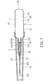
- the first preferred embodiment of an intravenous catheter introducing device is shown to comprise a needle assembly 2 and a flashback member 1.
- the needle assembly 2 includes a needle cannula 21, a catheter hub 22, a tubular catheter 23, and a tip protector 24.
- the needle cannula 21 has a front segment 213 terminating at a tip end 212, and a rear connecting segment 211 opposite to the front segment 213.
- the catheter hub 22 defines a duct 221 therein, which permits extension of the front segment 213 of the needle cannula 21 therethrough.
- the tubular catheter 23 has a proximate segment which is inserted into the duct 221 of the catheter hub 22, and a distal segment which extends from the proximate segment and which surrounds and sheathes the front segment 213 of the needle cannula 21 while permitting the tip end 212 to project forwardly of the distal segment for piercing the skin of a patient.
- the flashback member 1 has front and rear ends 122,121 opposite to each other in a longitudinal direction, and a surrounding wall 12 which interconnects the front and rear ends 122,121.
- the surrounding wall 12 includes a large-diameter rear wall portion 123 proximate to the rear end 121 and cooperating with the rear end 121 to define a flashback chamber 11 with an accommodation space confined thereby, andasmall-diameterfrontwallportion124 opposite to the rear wall portion 123 in the longitudinal direction and proximate to the front end 122.
- a tubular needle seat 25 which is disposed to be surrounded by and which is integrally formed with the front wall portion 124, is configured to secure the rear connecting segment 211 of the needle cannula 21 to the front wall portion 124 so as to permit the needle cannula 21 to be fluidly communicated with the flashback chamber 11.
- the rear wall portion 123 is integrally formed with the rear end 121.
- the flashback chamber 21 is made from a translucent deformable material such that the volume of the accommodation space is variable when the flashback chamber 21 is subjected to application of a manual force, and has an outer wall surface 111, and an inner wall surface 112 which is opposite to the outer wall surface 111 and which confronts the accommodation space.
- a pressure counteracting member 16 is interposed between and is integrally formed with the inner and outer wall surfaces 111,112.
- the pressure counteracting member 16 acquires an urging force which resists the first biasing force so as to hold the flashback chamber 11 in the ready position without the need for application of a manual force once the tip end 212 has pierced into the skin in search of the vein.
- the tip protector 24 is detachably sleeved on the rear wall portion 123 adjacent to the front wall portion 124 for shielding the needle cannula 21, the catheter hub 22 and the tubular catheter 23.
- the user can, with one hand, hold and squeeze the rear wall portion 123, as shown in Fig. 5, and pierce the skin of a patient with the tip end 212.
- the user can then gradually release the rear wall portion 123 such that the urging force is generated in the counteracting member 16 to facilitate the flow of blood into the flashback chamber 11, thereby permitting the user to check whether the tubular catheter 23 has been successfully introduced into a target vein of the patient.
- the user can separate the catheter hub 22 from the flashback member 1 with the other hand, and sleeve the tip protector 24 on the rear wall portion 123 to shield the used needle cannula 21 for subsequent safe disposal.
- the flashback chamber 11 can be held in the ready position as shown in Fig. 5 by the first biasing force without application of any manual force until the blood flows into the flashback chamber 11 through the needle cannula 21 by virtue of the urging force of the pressure counteracting member 16, i.e. , the restoring force of the deformable material of the pressure counteracting member 16.
- the catheter introducing operation is convenient to conduct.
- the second preferred embodiment of an intravenous catheter introducing device is shown to be similar to the first preferred embodiment in construction.
- the tubular needle seat 25 has a rear coupling portion 251 which is threadedly engageable with the front wall portion 124 of the flashback member 1 instead of being integrally formed with the front wall portion 124, and a front securing portion 252 which is configured to secure the rear connecting segment 211 of the needle cannula 21 such that the needle cannula 21 is fluidly communicated with the flashback chamber 11.
- the catheter hub 22 is detachably sleeved on the front securing portion 252.
- the third preferred embodiment of an intravenous catheter introducing device is shown to be similar to the second preferred embodiment in construction.
- the difference resides in that the rear coupling portion 251 of the needle seat 25 is detachably sleeved on the front wall portion 124 of the flashback member 1.
- the tip protector 24 is detachably sleeved on the catheter hub 22 for shielding the needle cannula 21 and the tubular catheter 23 before use.
- the tip protector 24 is configured to be detachably sleeved on the rear coupling portion 251 of the needle seat 25 after the catheter hub 22 is detached from the front securing portion 252, for shielding the used needle cannula 21.
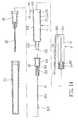
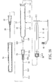
- a plunger 3 includes a plunger head 33 and a plunger stem 31.
- the plunger head 33 is configured to be in fluidly tight contact with, and to be slidable relative to, the inner wall surface 112 of the flashback member 1 in the longitudinal direction.
- the plunger stem 31 has a securing end 312 fixed to the plunger head 33, and an actuated end 311 which is opposite to the securing end 312 in the longitudinal direction, and which extends outwardly of the end opening of the rear end 121 to be actuated so as to move the plunger head 33 to slide along the inner wall surface 112 from a push-out position, as shown in Fig. 11, where the plunger head 33 is closer to the front wall portion 124, to a pull-in position, as shown in Fig.
- the pressure counteracting member includes a retaining portion 14 and an actuator 32.
- the retaining portion 14 is fixed to the outer wall surface 111 adjacent to the rear end 121 of the flashback member 1, and has a confining hole 141 extending therethrough in the longitudinal direction, and an engaging slot 15 which is communicated with the confining hole 141 in a transverse direction relative to the longitudinal direction.
- the actuator 32 has a rear fixed end 325 which is integrally formed with the actuated end 311, a tongue portion 326 which extends forwardly from the rear fixed end 325 to extend through the confining hole 141 and which terminates at a front pushed end 321, a plurality of retained regions 324 which are in the form of protrusions disposed on the tongue portion 326 and which are spaced apart from one another in the longitudinal direction, and a longitudinally extending reinforcing ridge 323 which is disposed on the tongue portion 326 to increase the stiffness of the tongue portion 326.
- the tongue portion 326 is configured to acquire a second biasing force that biases the tongue portion 326 to a retained position, as shown in Fig.
- the tongue portion 326 is displaceable relative to the plunger stem 31 by a manual force to a released position, as shown in Fig. 12, where the tongue portion 326 is released from the retaining portion 14 so as to permit the sliding movement of the plunger head 33 along the inner wall surface 112.
- the actuator 32 further has a pair of limiting barriers 322 which are disposed between the retained regions 324 and the front pushed end 321, and which are configured to extend transversely to be blocked by the retaining portion 14 when the tongue portion 326 is in the released position so as to prevent excess rearward movement of the plunger head 33 relative to the inner wall surface 112.
- the flashback member 1 has a pair of lugs 13 which are disposed on and which extend from the outer wall surface 111 for gripping by a user's fingers so as to facilitate pulling of the plunger head 33 to the pull-in position.
- the user can hold the rear wall portion 123 with one hand, as shown in Fig. 12, and pierce a target vein of a patient with the tip end 212 so that blood flows into the flashback chamber 11 to indicate a successful introduction of the tubular catheter 23. If blood is not observed in the flashback chamber 11, the user can press the lugs 13 with his/her thumb and middle finger, push the front pushed end 321 to displace the tongue portion 326 to the released position, and move the plunger head 33 rearwardly to the pull-in position so as to generate a reduced pressure in the flashback chamber 11 to thereby facilitate flow of blood into the flashback chamber 11. Referring to Fig. 13, the user can then separate the catheter hub 22 from the flashback member 1 with the other hand, and sleeve the tip protector 24 on the rear wall portion 123 to shield the used needle cannula 21 for subsequent safe disposal.
- the plunger head 33 can be retained relative to the inner wall surface 112 against the first biasing force without application of any manual force, thereby facilitating the catheter introducing operation.
- the fifth preferred embodiment of an intravenous catheter introducing device is shown to be similar to the fourth preferred embodiment in construction.
- the tubular needle seat 25 has a rear coupling portion 251 which is detachably sleeved on the front wall portion 124 instead of being integrally formed with the front wall portion 124, and a front securing portion 252 which is configured to secure the rear connecting segment 211 of the needle cannula 21 such that the needle cannula 21 is fluidly communicated with the flashback chamber 11.
- the catheter hub 22 is detachably sleeved on the front securing portion 252.
- the tip protector 24 is detachably sleeved on the catheter hub 22 for shielding the needle cannula 21 and the tubular catheter 23 before use. As shown in Fig. 15, the tip protector 24 is configured to be detachably sleeved on the rear coupling portion 251 of the tubular needle seat 25 after the catheter hub 22 is detached from the front securing portion 252, for shielding the used needle cannula 21.
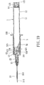
- the sixth preferred embodiment of an intravenous catheter introducing device is shown to be similar to the first preferred embodiment in construction.
- the intravenous catheter introducing device comprises a needle assembly 2, a shell member 5, and a flashback member 1.
- the needle assembly 2 includes a needle cannula 21, a needle seat 25, a catheter hub 22, a tubular catheter 23, a tip protector 24, and an internal needle 28.
- the internal needle 28 is integrally formed with and extends rearwardly from a rear connecting segment 211 of the needle cannula 21 in the longitudinal direction, and terminates at a tip end.
- the needle seat 25 is disposed to secure the rear connecting segment 211 of the needle cannula 21.
- the shell member 5 is integrally formed with and extends rearwardly from the needle seat 25 to surround the internal needle 28, and terminates at a rear access end 521, thereby defining a receiving chamber 51 for detachably receiving the flashback member 1 through the rear access end 521.
- a partition member 53 which is made from an air-permeable and liquid-impermeable material, is disposed in the receiving chamber 51, and is configured to air-tightly engage and to be movable relative to, the shell member 5.
- the partition member 53 has an engaging portion 531 formed on a side thereof.
- An annular barrier 525 extends inwardly and radially from the shell member 5.
- a front sealing member 63 is disposed to be in air-tight engagement with the front wall portion 124 of the flashback member 1 so as to seal the front end 122.
- a rear sealing member 64 is disposed to be in air-tight engagement with the rear wall portion 123 so as to seal the rear end 121, thereby confining the flashback chamber 11.
- the front sealing member 63 has an engaging recess 631 facing forwardly. Fluid with a reduced pressure is disposed in the flashback chamber 11.
- An engaging portion 125 is disposed on and extends from the inner wall surface 112 adjacent to the rear end 121 to serve as the pressure counteracting member such that the rear sealing member 64 is blocked by the engaging portion 125 so as tomaintain the flashback chamber 11 with the reduced pressure.
- the user can hold the shell member 5 with one hand, as shown in Fig. 17, and pierce a target vein of a patient with the tip end 212 so that blood flows into the receiving chamber 51 to indicate a successful introduction of the tubular catheter 23. If blood is not observed in the receiving chamber 51, the user can insert the flashback member 1 into the receiving chamber 51 such that the engaging portion 531 engages the engaging recess 631. Subsequently, the partition member 53 is pushed by the flashback member 1 to permit the internal needle 28 to pierce through the partition member 53.
- a subsequent pushing action of the flashback member 1 results inpassingof the internal needle 28 through the front sealing member 63 so as to fluidly communicate the flashback chamber 11 with the needle cannula 21, thereby facilitating the flow of blood into the flashback chamber 11 by means of the reduced pressure.
- the blood can be collected into the flashback chamber 11 for taking a blood sample.
- another flashback member 1, which has a longer flashback chamber 11, is used for collecting a larger amount of blood sample as required.
- the flashback member 1 can be pulled rearwardly to be removed from the shell member 5.
- the partition member 53 is prevented from being removed from the shell member 5 through the rear access end 521 by virtue of the annular barrier 525.
- the flashback member 1, in which the blood sample is collected can be transferred for the subsequent medical tests.
- the risk of pollution and infection and the amount of medical waste can be relatively reduced.
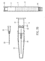
- the seventh preferred embodiment of an intravenous catheter introducing device is shown to be similar to the sixth preferred embodiment in construction.
- the internal needle 28 of the seventh embodiment is separately formed, and has a first segment which extends into the receiving chamber 51 of the shell member 5 to be surrounded by the shell member 5, and a second segment which is opposite to the first segment and which is surrounded and secured by a needle hub member 524 that extends forwardly from the shell member 5.
- the needle seat 25 has a front securing portion 252 which is configured to secure the rear connecting segment 211 of the needle cannula 21, and a rear coupling portion 251 which is detachably sleeved on the needle hub member 524 such that the needle cannula 21 is fluidly communicated with the internal needle 28.
- the catheter hub 22 is detachably sleeved on the front securing portion 252.
- the rear sealing member 64 is disposed to be movable relative to the surrounding wall 12 in the longitudinal direction.
- a plunger 65 has a head portion 651 which is connected to the rear sealing member 64, and a shank portion 652 which extends rearwardly from the head portion 651 and outwardly of the rear end 121 such that the plunger 65 is pulled rearwardly to move the rear sealing member 64 towards the rear end 121 so as to generate the reduced pressure in the flashback chamber 11.
- the shank portion 652 has a weakening region 653 which is formed proximate to the head portion 651 for facilitating breaking of the shank portion 652 after the rearwardly pulling operation of the plunger 65.
- the pressure counteracting member includes first and second engaging portions 125,654 which are disposed on the rear wall portion 123 of the flashback member 1 adjacent to the rear end 121 and the head portion 651, respectively, and which are configured such that a forced movement of the second engaging portion 654 over the first engaging portion 125 by virtue of rearwardly pulling the head portion 651 results in a press-fit engagement between the first and second engaging portions 125,654, thereby preventing a forward movement of the rear sealing member 64 and thereby holding the flashback chamber 11 in the ready position.
- the eighth preferred embodiment of an intravenous catheter introducing device is shown to be similar to the fourth preferred embodiment in construction.
- the pressure counteracting member includes a traction ring 41 and a connecting bar 42.
- the traction ring 41 is sleeved on and is in frictional engagement with the outer wall surface 111 of the flashback chamber 11 with a frictional force.
- the connecting bar 42 is disposed to interconnect the traction ring 41 and the actuated end 311 of the plunger stem 31 so as to permit the traction ring 41 to be moved with the plunger head 3 3 .
- the frictional force can hold the traction ring 41 onto the outer wall surface 111 against the pressure difference, thereby holding the plunger head 33 at the pull-in position.
- the ninth preferred embodiment of an intravenous catheter introducing device is shown to be similar to the eighth preferred embodiment in construction.
- the tubular needle seat 25 has a rear coupling portion 251 which is detachably sleeved on the front wall portion 124 instead of being integrally formed with the front wall portion 124, and a front securing portion 252 which is configured to secure the rear connecting segment 211 of the needle cannula 21 such that the needle cannula 21 is fluidly communicated with the flashback chamber 11.
- the catheter hub 22 is detachably sleeved on the front securing portion 252.
- the tip protector 24 is detachably sleeved on the catheter hub 22 for shielding the needle cannula 21 and the tubular catheter 23 before use.
- the tip protector 24 is configured to be detachably sleeved on the rear coupling portion 251 of the tubular needle seat 25 after the catheter hub 22 is detached from the front securing portion 252, for shielding the used needle cannula 21.
Priority Applications (1)
| Application Number | Priority Date | Filing Date | Title |
|---|---|---|---|
| EP06254061A EP1884258A1 (fr) | 2006-08-02 | 2006-08-02 | Dispositif d'introduction d'un cathéter intraveineux muni d'une chambre de retour |
Applications Claiming Priority (1)
| Application Number | Priority Date | Filing Date | Title |
|---|---|---|---|
| EP06254061A EP1884258A1 (fr) | 2006-08-02 | 2006-08-02 | Dispositif d'introduction d'un cathéter intraveineux muni d'une chambre de retour |
Publications (1)
| Publication Number | Publication Date |
|---|---|
| EP1884258A1 true EP1884258A1 (fr) | 2008-02-06 |
Family
ID=37460269
Family Applications (1)
| Application Number | Title | Priority Date | Filing Date |
|---|---|---|---|
| EP06254061A Withdrawn EP1884258A1 (fr) | 2006-08-02 | 2006-08-02 | Dispositif d'introduction d'un cathéter intraveineux muni d'une chambre de retour |
Country Status (1)
| Country | Link |
|---|---|
| EP (1) | EP1884258A1 (fr) |
Citations (7)
| Publication number | Priority date | Publication date | Assignee | Title |
|---|---|---|---|---|
| US2739591A (en) | 1955-04-12 | 1956-03-27 | Donald E Yochem | Multiple dose hypodermic syringe control |
| US3459183A (en) | 1966-05-20 | 1969-08-05 | Voys Inc Le | Catheter placement unit with anesthetic |
| US3500828A (en) | 1966-08-31 | 1970-03-17 | Fred W Podhora | Intravenous catheter apparatus |
| WO1998057685A1 (fr) | 1997-06-17 | 1998-12-23 | Injectimed, Inc. | Procede et appareil permettant d'introduire un catheter intraveineux |
| WO1999003417A1 (fr) * | 1997-07-17 | 1999-01-28 | Medical Components, Inc. | Dispositif d'introduction de fil-guide de catheter et technique correspondante |
| US20030004437A1 (en) | 2001-06-20 | 2003-01-02 | Collins Margie M. | Blood collection safety device |
| US20040153037A1 (en) | 2003-01-17 | 2004-08-05 | Taiject Medical Device Co., Ltd. | Hypodermic syringe having plunger pull-out stopping structure |
-
2006
- 2006-08-02 EP EP06254061A patent/EP1884258A1/fr not_active Withdrawn
Patent Citations (7)
| Publication number | Priority date | Publication date | Assignee | Title |
|---|---|---|---|---|
| US2739591A (en) | 1955-04-12 | 1956-03-27 | Donald E Yochem | Multiple dose hypodermic syringe control |
| US3459183A (en) | 1966-05-20 | 1969-08-05 | Voys Inc Le | Catheter placement unit with anesthetic |
| US3500828A (en) | 1966-08-31 | 1970-03-17 | Fred W Podhora | Intravenous catheter apparatus |
| WO1998057685A1 (fr) | 1997-06-17 | 1998-12-23 | Injectimed, Inc. | Procede et appareil permettant d'introduire un catheter intraveineux |
| WO1999003417A1 (fr) * | 1997-07-17 | 1999-01-28 | Medical Components, Inc. | Dispositif d'introduction de fil-guide de catheter et technique correspondante |
| US20030004437A1 (en) | 2001-06-20 | 2003-01-02 | Collins Margie M. | Blood collection safety device |
| US20040153037A1 (en) | 2003-01-17 | 2004-08-05 | Taiject Medical Device Co., Ltd. | Hypodermic syringe having plunger pull-out stopping structure |
Similar Documents
| Publication | Publication Date | Title |
|---|---|---|
| US20070088278A1 (en) | Intravenous catheter introducing device with a flashback member | |
| EP1884257A1 (fr) | Dispositif permettant l'insertion d'un cathéter intraveineux avec un élément de sortie tubulaire | |
| US7771394B2 (en) | Intravenous catheter introducing device | |
| US7204813B2 (en) | Cannula retractable medical collection device | |
| CA2429759C (fr) | Dispositif d'insertion de catheter intraveineux | |
| US7753887B2 (en) | Retractable needle medical device | |
| US5352205A (en) | Bloodless insertion catheter assembly | |
| JP3796514B2 (ja) | 収納自在な穿刺針を備えた医療用器具及び同医療用器具の製造方法 | |
| US7524306B2 (en) | Catheter insertion device with retractable needle | |
| EP1457229B1 (fr) | Dispositif dinsertion d'un catheter intraveineux | |
| US20080287876A1 (en) | Intravenous catheter introducing device | |
| JPH11503643A (ja) | 点滴カテーテル差込み用安全スタイレット | |
| CZ296796B6 (cs) | Bezpecnostní zarízení pro zapouzdrení lékarské jehly | |
| EP1221301A2 (fr) | Appareillage de collecte de sang | |
| KR20080011014A (ko) | 안전 장치를 구비한 카테터-유도바늘 어셈블리 | |
| EP3484558A1 (fr) | Aiguille anesthésique à gainage automatique avec seringue spéciale | |
| JP3576765B2 (ja) | 留置針組立体 | |
| EP1884258A1 (fr) | Dispositif d'introduction d'un cathéter intraveineux muni d'une chambre de retour | |
| EP1944052B1 (fr) | Dispositif d'introduction intraveineuse d'un cathéter | |
| US20080234635A1 (en) | Disposable syringe guarded in a preuse position (II) | |
| EP1570784A1 (fr) | Dispositif médical de prélèvement de sang avec une canule rétractable | |
| EP2039383A1 (fr) | Seringue jetable conservée dans une position de pré-utilisation (II) | |
| CA2607399A1 (fr) | Dispositif d'insertion d'un catheter intraveineux | |
| EP2039385A1 (fr) | Seringue jetable conservée dans une position de pré-utilisation (I) | |
| AU2007229352B1 (en) | Intravenous catheter introducing device |
Legal Events
| Date | Code | Title | Description |
|---|---|---|---|
| PUAI | Public reference made under article 153(3) epc to a published international application that has entered the european phase |
Free format text: ORIGINAL CODE: 0009012 |
|
| AK | Designated contracting states |
Kind code of ref document: A1 Designated state(s): AT BE BG CH CY CZ DE DK EE ES FI FR GB GR HU IE IS IT LI LT LU LV MC NL PL PT RO SE SI SK TR |
|
| AX | Request for extension of the european patent |
Extension state: AL BA HR MK YU |
|
| 17P | Request for examination filed |
Effective date: 20080331 |
|
| 17Q | First examination report despatched |
Effective date: 20080430 |
|
| AKX | Designation fees paid |
Designated state(s): AT BE BG CH CY CZ DE DK EE ES FI FR GB GR HU IE IS IT LI LT LU LV MC NL PL PT RO SE SI SK TR |
|
| GRAP | Despatch of communication of intention to grant a patent |
Free format text: ORIGINAL CODE: EPIDOSNIGR1 |
|
| STAA | Information on the status of an ep patent application or granted ep patent |
Free format text: STATUS: THE APPLICATION IS DEEMED TO BE WITHDRAWN |
|
| 18D | Application deemed to be withdrawn |
Effective date: 20100306 |