EP1882101B1 - Pumpe - Google Patents
Pumpe Download PDFInfo
- Publication number
- EP1882101B1 EP1882101B1 EP05791474A EP05791474A EP1882101B1 EP 1882101 B1 EP1882101 B1 EP 1882101B1 EP 05791474 A EP05791474 A EP 05791474A EP 05791474 A EP05791474 A EP 05791474A EP 1882101 B1 EP1882101 B1 EP 1882101B1
- Authority
- EP
- European Patent Office
- Prior art keywords
- rotor
- intermediate element
- pump according
- clutch device
- pump
- Prior art date
- Legal status (The legal status is an assumption and is not a legal conclusion. Google has not performed a legal analysis and makes no representation as to the accuracy of the status listed.)
- Not-in-force
Links
Images


Classifications
-
- F—MECHANICAL ENGINEERING; LIGHTING; HEATING; WEAPONS; BLASTING
- F04—POSITIVE - DISPLACEMENT MACHINES FOR LIQUIDS; PUMPS FOR LIQUIDS OR ELASTIC FLUIDS
- F04C—ROTARY-PISTON, OR OSCILLATING-PISTON, POSITIVE-DISPLACEMENT MACHINES FOR LIQUIDS; ROTARY-PISTON, OR OSCILLATING-PISTON, POSITIVE-DISPLACEMENT PUMPS
- F04C29/00—Component parts, details or accessories of pumps or pumping installations, not provided for in groups F04C18/00 - F04C28/00
- F04C29/0042—Driving elements, brakes, couplings, transmissions specially adapted for pumps
- F04C29/005—Means for transmitting movement from the prime mover to driven parts of the pump, e.g. clutches, couplings, transmissions
-
- F—MECHANICAL ENGINEERING; LIGHTING; HEATING; WEAPONS; BLASTING
- F04—POSITIVE - DISPLACEMENT MACHINES FOR LIQUIDS; PUMPS FOR LIQUIDS OR ELASTIC FLUIDS
- F04C—ROTARY-PISTON, OR OSCILLATING-PISTON, POSITIVE-DISPLACEMENT MACHINES FOR LIQUIDS; ROTARY-PISTON, OR OSCILLATING-PISTON, POSITIVE-DISPLACEMENT PUMPS
- F04C29/00—Component parts, details or accessories of pumps or pumping installations, not provided for in groups F04C18/00 - F04C28/00
-
- F—MECHANICAL ENGINEERING; LIGHTING; HEATING; WEAPONS; BLASTING
- F04—POSITIVE - DISPLACEMENT MACHINES FOR LIQUIDS; PUMPS FOR LIQUIDS OR ELASTIC FLUIDS
- F04C—ROTARY-PISTON, OR OSCILLATING-PISTON, POSITIVE-DISPLACEMENT MACHINES FOR LIQUIDS; ROTARY-PISTON, OR OSCILLATING-PISTON, POSITIVE-DISPLACEMENT PUMPS
- F04C18/00—Rotary-piston pumps specially adapted for elastic fluids
- F04C18/30—Rotary-piston pumps specially adapted for elastic fluids having the characteristics covered by two or more of groups F04C18/02, F04C18/08, F04C18/22, F04C18/24, F04C18/48, or having the characteristics covered by one of these groups together with some other type of movement between co-operating members
- F04C18/34—Rotary-piston pumps specially adapted for elastic fluids having the characteristics covered by two or more of groups F04C18/02, F04C18/08, F04C18/22, F04C18/24, F04C18/48, or having the characteristics covered by one of these groups together with some other type of movement between co-operating members having the movement defined in group F04C18/08 or F04C18/22 and relative reciprocation between the co-operating members
- F04C18/344—Rotary-piston pumps specially adapted for elastic fluids having the characteristics covered by two or more of groups F04C18/02, F04C18/08, F04C18/22, F04C18/24, F04C18/48, or having the characteristics covered by one of these groups together with some other type of movement between co-operating members having the movement defined in group F04C18/08 or F04C18/22 and relative reciprocation between the co-operating members with vanes reciprocating with respect to the inner member
-
- F—MECHANICAL ENGINEERING; LIGHTING; HEATING; WEAPONS; BLASTING
- F04—POSITIVE - DISPLACEMENT MACHINES FOR LIQUIDS; PUMPS FOR LIQUIDS OR ELASTIC FLUIDS
- F04C—ROTARY-PISTON, OR OSCILLATING-PISTON, POSITIVE-DISPLACEMENT MACHINES FOR LIQUIDS; ROTARY-PISTON, OR OSCILLATING-PISTON, POSITIVE-DISPLACEMENT PUMPS
- F04C2220/00—Application
- F04C2220/10—Vacuum
Definitions
- the invention relates to a pump, in particular a vacuum pump for motor vehicles, wherein a rotor is rotatably mounted with at least one wing within a pump housing rotatably driven by a coupling device from the engine of the motor vehicle and between the rotor and clutch means an intermediate element is arranged, which is a captive connection and a Wear protection between the rotor and coupling device represents.
- Such pumps are known for example from the document G 85 09 505.2 U1.
- they have the disadvantage that the intermediate element, the coupling device so attached to the rotor that the coupling device can perform only a sliding movement, but no pivotal movement.
- a pump in particular a vacuum pump for motor vehicles, wherein a rotor is rotatably mounted with at least one wing within a pump housing and driven in rotation by means of a coupling device of an internal combustion engine of a motor vehicle and between the rotor and clutch means an intermediate element is arranged, which is a captive Represents connection and wear protection between the rotor and coupling device, according to the invention, the intermediate element forms a pivot bearing within the rotor for the coupling device.
- a pump is preferred in which the intermediate element is designed in such a way that the coupling device does not touch the rotor. This has the advantage that the intermediate element also forms a wear protection in the opposite direction of rotation, as it can occur, for example, when switching off the internal combustion engine or by the rotational movement superimposed vibrations.
- a pump according to the invention is characterized in that the intermediate element is designed as a substantially cap-shaped sheet metal part, which is arranged in a groove in the rotor and on the one hand produces a captive connection to the coupling device and allows pivotal movement of the coupling device and on the other hand establishes a fixed connection to the rotor.
- the coupling device essentially represents a strip-shaped part which has a rounded on one longitudinal side pivot member which is mounted within the intermediate member, and on the opposite longitudinal side of a cuboid engaging member which, for example, in a groove of a drive device, such as B. the camshaft of an internal combustion engine of a motor vehicle engages.
- a pump is preferred in which the coupling device additionally has lateral recesses into which the captive connections engage in the form of clip devices of the intermediate element.
- a pump according to the invention is characterized in that the coupling device is made of sintered steel or by stamping of rod material. Furthermore, a pump is preferred in which the rotor made of plastic, preferably made of PA6.6, or aluminum.
- a pump in which the rotor, the intermediate element and the coupling device after assembly, in particular after clipping, form a captive assembly.
- the elements of the assembly are connected to each other captive, but again releasably connected, wherein the intermediate element has so-called arc tongues.
- a pump is preferred in which after assembly, the elements of the assembly are permanently connected to each other, wherein the intermediate element has so-called Hakenzept, which function as barbs.
- a pump according to the invention is characterized in that the intermediate element is made of sheet metal by punching and bending. Furthermore, a pump is preferred in which the intermediate element has recesses on the narrow sides and in the region of the rounded bottom, which enable compression movements when the intermediate element is introduced into the rotor groove. Also, a pump is preferred in which the intermediate element produces a clamping connection in the rotor groove on the longitudinal sides and produces a clamping connection, in particular a clip connection, in the recesses of the coupling device on the transverse sides.
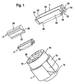
- FIG. 1 are the three components of the assembly to which the invention applies, namely a rotor 1 of a vacuum pump, an intermediate element 3 and a coupling device 5 shown in three-dimensional representation.
- the intermediate element 3 can be seen in more detail in an enlarged view 7.
- the rotor 1 which is preferably made of plastic, has a larger diameter cylindrical portion 10, which has a slot 12 for receiving a wing, not shown here. Vacuum pumps of this type are therefore also called monoerielzellenvakuumpumpen.
- the rotor 1 also has a smaller diameter cylindrical part 14, which also serves as a sliding bearing within a pump housing, not shown here.
- the rotor 1 has a second smaller diameter cylindrical part 16, which serves as a second bearing within the vacuum pump housing.
- the cylindrical part 14 has an end face 18 in which a groove 20 is embedded.
- the groove 20 serves to receive the intermediate element 3 or 7, which may be made for example of a sheet iron material or other metal material by punching and bending.
- the intermediate element 3 can be spring-loaded by a type Clamping connection, as will be described later, are inserted into the groove 20 of the rotor 1.
- a coupling device 5 a strip-like element is used, which has on one longitudinal side a rounded longitudinal surface 22 and on the opposite longitudinal side of an approximately cuboid engaging part 24.
- the longitudinal side with the rounded pivot part 22 of the coupling device 5 is mounted in a rounded coupling part 26 of the intermediate element 7 and 3, respectively, and thus can allow slight pivoting movements of the coupling device 5 within the intermediate element 7.
- the coupling device can engage, for example, in a slot of a camshaft so that the rotor 1 of the vacuum pump is rotationally driven via the coupling device 5 by the camshaft and thus by the internal combustion engine.
- the coupling element 5 is for transmitting the corresponding driving forces of a metal material, preferably made of sintered metal.
- the rotor 1 is made of a softer plastic material to reduce the mass forces, a direct intervention of the coupling device 5 in the plastic groove 20 of the rotor 1 would lead to considerable wear and possibly to destruction of the plastic rotor, since the coupling device 5 both against the Rotor 1 and relative to the driving camshaft relative movements to compensate for misalignment between the camshaft and the plastic rotor must perform.
- the intermediate element 3 or 7 is required.
- it is necessary that the intermediate element 3 or 7 is fixedly arranged in the rotor groove 20, so that no relative movements between the intermediate element 3 or 7 and the rotor groove 20 are possible.
- the intermediate element 3, 7 must also be designed so that the corresponding pivoting movement can be carried out within the intermediate element 3, 7. This is ensured by the rounded bottom 26 of the intermediate element and the rounded longitudinal side 22 of the coupling device 5.
- the coupling device 5 further has on its narrow sides two additional lateral recesses 28, wherein upon insertion of the coupling device 5 in the intermediate element 7 two tongues 34 are pressed resiliently with spherical segment-like recesses 30, which then engage in the recesses 28 and thus the coupling device 5 captive connect with the firmly seated in the plastic rotor 1 intermediate element 7, while still a slight pivotal movement of the coupling element 5 within the connecting element 7 is possible.
- FIG. 2 are the three elements rotor 1, intermediate element 3 or 7 and coupling device 5 in the assembled state shown in cross section.
- cross-section is particularly easy to see that engage in the recesses 28 of the coupling element 5, the spherical portion-shaped depressions 30 of the intermediate element 3 and 7 respectively.
- the rounded bottom 26 and the tongues 34 with the spherical portion-shaped depressions 30 ensure that the coupling element 5 does not come into contact with the walls of the groove 20 in the plastic rotor 1.
- a corresponding wear between the coupling device 5 and the plastic rotor 1 is avoided, and the maximum permissible surface pressure on the walls of the groove 20 of the plastic rotor 1 is not exceeded.
- FIG. 3 are the three components of another assembly according to the invention, essentially as in FIG. 1 listed, shown.
- the difference lies in the design of the intermediate element 39, which now has spring tongues 40 with hook-shaped detent bodies 42 on its narrow sides.
- the necessary spring movement is in turn through the recesses 32 and 38, as already in FIG. 1 described, allows.
- the invention thus makes it possible that the pivotable drive coupling 5 of a vacuum pump by applying a slight mounting force captive, in particular clipped can be mounted.
- the clutch 5 transmits the rotational movement of a camshaft via a retaining plate 3, 7, 39 (use for reducing wear) to the rotor 1 and can compensate axially and radially in addition to pivoting an offset.
- the intermediate element 3, 7, 39, so the retaining plate can be formed by punching and bending a tab (42), nose or bulge 30 in the retaining plate in the coupling longitudinal axis and corresponding recess 28 on the coupling for fixing. Equally by resilient longitudinal walls 36 as a clamping connection or as a clip connection, the fixation of the intermediate element 3 or 7, so the holding plate, are executed in the rotor 1.
Landscapes
- Engineering & Computer Science (AREA)
- Mechanical Engineering (AREA)
- General Engineering & Computer Science (AREA)
- Rotary Pumps (AREA)
- Applications Or Details Of Rotary Compressors (AREA)
- Fluid-Driven Valves (AREA)
- Eye Examination Apparatus (AREA)
Description
- Die Erfindung betrifft eine Pumpe, insbesondere Vakuumpumpe für Kraftfahrzeuge, wobei ein Rotor mit zumindest einem Flügel innerhalb eines Pumpengehäuses drehantreibbar gelagert ist und mittels einer Kupplungseinrichtung vom Verbrennungsmotor des Kraftfahrzeugs drehangetrieben wird und zwischen Rotor und Kupplungseinrichtung ein Zwischenelement angeordnet ist, welches eine verliersichere Verbindung und einen Verschleißschutz zwischen Rotor und Kupplungseinrichtung darstellt.
- Derartige Pumpen sind beispielsweise aus der Druckschrift G 85 09 505.2 U1 bekannt. Sie weisen allerdings den Nachteil auf, dass das Zwischenelement die Kupplungseinrichtung derartig am Rotor befestigt, dass die Kupplungseinrichtung nur eine Schiebebewegung, aber keine Schwenkbewegung vollziehen kann. Entsprechende Fluchtungsfehler zwischen der Antriebsvorrichtung und dem Rotor, welche eine Schwenkbewegung des Kupplungselementes erfordern würden, können somit nicht ausgeglichen werden.
- Es ist daher Aufgabe der Erfindung, eine Pumpe darzustellen, die diese Nachteile nicht aufweist.
- Die Aufgabe wird gelöst durch eine Pumpe, insbesondere Vakuumpumpe für Kraftfahrzeuge, wobei ein Rotor mit zumindest einem Flügel innerhalb eines Pumpengehäuses drehantreibbar gelagert ist und mittels einer Kupplungseinrichtung von einem Verbrennungsmotor eines Kraftfahrzeuges drehantreibbar ist und zwischen Rotor und Kupplungseinrichtung ein Zwischenelement angeordnet ist, welches eine verliersichere Verbindung und einen Verschleißschutz zwischen Rotor und Kupplungseinrichtung darstellt, wobei erfindungsgemäß das Zwischenelement eine Schwenklagerung innerhalb des Rotors für die Kupplungseinrichtung bildet. Bevorzugt wird eine Pumpe, bei welcher das Zwischenelement derartig ausgebildet ist, dass die Kupplungseinrichtung den Rotor nicht berührt. Das hat den Vorteil, dass das Zwischenelement auch einen Verschleißschutz bei entgegengesetzter Drehrichtung bildet, wie es beispielsweise beim Abschalten des Verbrennungsmotors bzw. durch der Drehbewegung überlagerte Schwingungen auftreten kann.
- Eine erfindungsgemäße Pumpe zeichnet sich dadurch aus, dass das Zwischenelement als im Wesentlichen kappenförmiges Blechteil ausgebildet ist, welches in einer Nut im Rotor angeordnet ist und einerseits eine verliersichere Verbindung zur Kupplungseinrichtung herstellt und eine Schwenkbewegung der Kupplungseinrichtung ermöglicht und andererseits eine feste Verbindung zum Rotor herstellt. Bevorzugt wird eine Pumpe, bei welcher die Kupplungseinrichtung im Wesentlichen ein leistenförmiges Teil darstellt, welches einen an einer Längsseite abgerundeten Schwenkteil, welcher innerhalb des Zwischenelements gelagert ist, und an der gegenüber liegenden Längsseite einen quaderförmigen Eingriffsteil aufweist, welcher beispielsweise in eine Nut einer Antriebsvorrichtung, wie z. B. der Nockenwelle eines Verbrennungsmotors eines Kraftfahrzeuges, eingreift.
- Bevorzugt wird eine Pumpe, bei welcher die Kupplungseinrichtung zusätzlich seitliche Ausnehmungen aufweist, in welche die verliersicheren Verbindungen in Form von Clipsvorrichtungen des Zwischenelements einrasten.
- Bevorzugt wird weiterhin eine Pumpe, bei welcher die Kupplungseinrichtung im Zwischenelement im Rotor schwenkbar und in der Nut der Antriebsvorrichtung um ihre Längsachse verschiebbar gelagert ist. Das hat den Vorteil, dass ein entsprechender Versatz zwischen der Antriebswelle und dem Rotor einerseits durch die Schwenkbewegung und andererseits durch das Verschieben in der Nut innerhalb der Antriebsvorrichtung ausgeglichen werden kann.
- Eine erfindungsgemäße Pumpe zeichnet sich dadurch aus, dass die Kupplungseinrichtung aus Sinterstahl oder durch Stanzen aus Stangenmaterial hergestellt ist. Weiterhin wird eine Pumpe bevorzugt, bei welcher der Rotor aus Kunststoff, vorzugsweise aus PA6.6, oder Aluminium, hergestellt ist.
- Auch wird eine Pumpe bevorzugt, bei welcher der Rotor, das Zwischenelement und die Kupplungseinrichtung nach der Montage, insbesondere nach Zusammenclipsen, eine unverlierbare Baugruppe bilden. Bevorzugt wird eine Pumpe, bei welcher nach Montage die Elemente der Baugruppe miteinander unverlierbar, aber wieder lösbar verbunden sind, wobei das Zwischenelement so genannte Bogenzungen aufweist. Weiterhin wird eine Pumpe bevorzugt, bei welcher nach Montage die Elemente der Baugruppe miteinander unlösbar verbunden sind, wobei das Zwischenelement so genannte Hakenzungen aufweist, welche als Widerhaken funktionieren.
- Eine erfindungsgemäße Pumpe zeichnet sich dadurch aus, dass das Zwischenelement aus Blech durch Stanzen und Biegen hergestellt ist. Bevorzugt wird weiterhin eine Pumpe, bei welcher das Zwischenelement an den Schmalseiten und im Bereich des abgerundeten Bodens Aussparungen aufweist, welche Einfederungsbewegungen beim Einbringen des Zwischenelements in die Rotornut ermöglichen. Auch wird eine Pumpe bevorzugt, bei welcher das Zwischenelement an den Längsseiten eine Klemmverbindung in der Rotornut herstellt und an den Querseiten eine Klemmverbindung, insbesondere eine Clipsverbindung, in den Ausnehmungen der Kupplungseinrichtung herstellt.
- Die Erfindung wird nun anhand der Figuren beschrieben.
- Figur 1
- zeigt in einer dreidimensionalen Darstellung die drei Bauelemente Rotor, Zwischenelement und Kupplungseinrichtung.
- Figur 2
- zeigt im Querschnitt die zusammengebauten Elemente aus
Figur 1 . - Figur 3
- zeigt eine Variante zur
Figur 1 mit einem anderen Zwischenelement. - Figur 4
- zeigt den Zusammenbau der Elemente aus
Figur 3 im Querschnitt. - In
Figur 1 sind die drei Bauelemente der Baugruppe, auf welche die Erfindung zutrifft, nämlich ein Rotor 1 einer Vakuumpumpe, ein Zwischenelement 3 und eine Kupplungseinrichtung 5 in dreidimensionaler Darstellung gezeigt. Das Zwischenelement 3 ist noch mal in einer vergrößerten Darstellung 7 genauer zu erkennen. Der Rotor 1, welcher vorzugsweise aus Kunststoff ausgeführt ist, besitzt einen durchmessergrößeren zylindrischen Teil 10, der einen Schlitz 12 zur Aufnahme eines hier nicht dargestellten Flügels aufweist. Vakuumpumpen dieser Bauart nennt man daher auch Monoflügelzellenvakuumpumpen. Der Rotor 1 weist ferner einen durchmesserkleineren zylindrischen Teil 14 auf, der auch als Gleitlager innerhalb eines hier nicht dargestellten Pumpengehäuses dient. Ferner weist der Rotor 1 einen zweiten durchmesserkleineren zylindrischen Teil 16 auf, der als zweites Lager innerhalb des Vakuumpumpengehäuses dient. Der zylindrische Teil 14 weist eine Stirnfläche 18 auf, in welcher eine Nut 20 eingelassen ist. Die Nut 20 dient zur Aufnahme des Zwischenelementes 3 bzw. 7, welches beispielsweise aus einem Eisenblechwerkstoff oder einem anderen Metallwerkstoff durch Stanzen und Biegen hergestellt sein kann. Das Zwischenelement 3 kann durch eine Art fedemder Klemmverbindung, wie später noch beschrieben wird, in die Nut 20 des Rotors 1 eingesetzt werden. Als Kupplungseinrichtung 5 wird ein leistenartiges Element verwendet, welches auf einer Längsseite eine abgerundete Längsfläche 22 und auf der entgegengesetzten Längsseite ein etwa quaderförmiges Eingriffsteil 24 aufweist. Die Längsseite mit dem abgerundeten Schwenkteil 22 der Kupplungseinrichtung 5 wird in einem abgerundeten Kuppenteil 26 des Zwischenelements 7 bzw. 3 gelagert und kann damit innerhalb des Zwischenelementes 7 leichte Schwenkbewegungen der Kupplungseinrichtung 5 zulassen. Mit dem quaderförmigen Eingriffsteil 24, welcher über das Zwischenelement hervorragt, kann die Kupplungseinrichtung beispielsweise in einen Schlitz einer Nockenwelle eingreifen, so dass der Rotor 1 der Vakuumpumpe über die Kupplungseinrichtung 5 von der Nockenwelle und damit vom Verbrennungsmotor drehangetrieben wird. Das Kupplungselement 5 ist zur Übertragung der entsprechenden Antriebskräfte aus einem Metallwerkstoff, vorzugsweise aus Sintermetall, hergestellt. Da der Rotor 1 zur Verringerung der Massenkräfte aus einem weicheren Kunststoffwerkstoff hergestellt ist, würde ein direktes Eingreifen der Kupplungseinrichtung 5 in die Kunststoffnut 20 des Rotors 1 zu einem erheblichen Verschleiß und ggf. zu einer Zerstörung des Kunststoffrotors führen, da die Kupplungseinrichtung 5 sowohl gegenüber dem Rotor 1 als auch gegenüber der antreibenden Nockenwelle Relativbewegungen zum Ausgleich von Fluchtungsfehlern zwischen der Nockenwelle und dem Kunststoffrotor durchführen muss. Unter anderem zur Vermeidung dieses Verschleißproblems wird das Zwischenelement 3 bzw. 7 benötigt. Dazu ist erforderlich, dass das Zwischenelement 3 bzw. 7 fest in der Rotornut 20 angeordnet ist, also keine Relativbewegungen zwischen dem Zwischenelement 3 bzw. 7 und der Rotornut 20 möglich sind. Zur Verwendung des schwenkbaren Kupplungselementes 5 muss das Zwischenelement 3, 7 allerdings auch so ausgebildet sein, dass die entsprechende Schwenkbewegung innerhalb des Zwischenelementes 3, 7 durchgeführt werden kann. Das wird durch den abgerundeten Boden 26 des Zwischenelementes und die abgerundete Längsseite 22 der Kupplungseinrichtung 5 gewährleistet. Die Kupplungseinrichtung 5 weist ferner an ihren Schmalseiten zwei zusätzliche seitliche Ausnehmungen 28 auf, wobei bei Einbringung der Kupplungseinrichtung 5 in das Zwischenelement 7 zwei Zungen 34 mit kugelsegmentartigen Vertiefungen 30 federnd auseinander gedrückt werden, welche danach in die Vertiefungen 28 einrasten und damit die Kupplungseinrichtung 5 unverlierbar mit dem fest im Kunststoffrotor 1 sitzenden Zwischenelement 7 verbinden, wobei trotzdem eine leichte Schwenkbewegung des Kupplungselementes 5 innerhalb des Verbindungselementes 7 möglich ist. Um das Federn der Zungen 34 mit den kugelabschnittsförmigen Vertiefungen 30 zu ermöglichen, sind entsprechende Schlitze 32 zwischen den federnden Zungen 34 und den Längsseitenwänden 36 des Zwischenelements 7 vorgesehen. Ferner weist das Zwischenelement 7 im Bereich des abgerundeten Bodens 26 an den Schmalseiten Ausnehmungen 38 auf, wodurch sowohl ein Freiraum für eine federnde Bewegung der Zungen 34 als auch ein Freiraum für eine federnde Einklemmbewegung der Seitenflächen 36 in der Nut 20 geschaffen wird. Durch das Einclipsen des Kupplungselementes 5 innerhalb des Verbindungselementes 7 ist das Kupplungselement 5 damit zwar schwenkbar, aber nicht radial verschiebbar innerhalb des Rotors 1 gelagert. Die radiale Verschieblichkeit muss zwischen dem quaderförmigen Eingriffsteil 24 und einem entsprechenden Schlitz in der Nockenwelle des Verbrennungsmotors ermöglicht werden, um Achsversätze zwischen Antriebswelle und Pumpenrotor ausgleichen zu können. - In
Figur 2 sind die drei Elemente Rotor 1, Zwischenelement 3 bzw. 7 und Kupplungseinrichtung 5 in zusammengebautem Zustand im Querschnitt dargestellt. Im Querschnitt ist besonders gut zu erkennen, dass in den Ausnehmungen 28 des Kupplungselements 5 die kugelabschnittsförmigen Vertiefungen 30 des Zwischenelementes 3 bzw. 7 einrasten. Auch ist im Querschnitt gut zu erkennen, dass der abgerundete Boden 26 und die Zungen 34 mit den kugelabschnittsförmigen Vertiefungen 30 dafür sorgen, dass das Kupplungselement 5 nicht mit den Wandungen der Nut 20 im Kunststoffrotor 1 in Berührung kommen. Damit wird ein entsprechender Verschleiß zwischen der Kupplungseinrichtung 5 und dem Kunststoffrotor 1 vermieden, und die maximal zulässige Flächenpressung auf die Wandungen der Nut 20 des Kunststoffrotors 1 wird nicht überschritten. - In
Figur 3 sind die drei Bauelemente einer weiteren erfindungsgemäßen Baugruppe, im Wesentlichen wie inFigur 1 aufgeführt, dargestellt. Der Unterschied liegt in der Ausführung des Zwischenelementes 39, welches nun an seinen Schmalseiten Federzungen 40 mit hakenförmigen Rastkörpern 42 aufweist. Die notwendige Federbewegung wird wiederum durch die Ausnehmungen 32 und 38, wie bereits inFigur 1 beschrieben, ermöglicht. - Im Querschnitt in
Figur 4 ist klar zu erkennen, dass die hakenförmigen Rastkörper 42, welche hier wiederum in die Ausnehmungen 28 einrasten, in diesem Fall beim Herausziehen des Kupplungselementes 5 wie Widerhaken dieser Bewegung entgegenstehen würden. In diesem Fall entsteht durch die spezielle Ausformung der Rastelemente 42 eine clipsbare, aber nach Montage unlösbare Verbindung zwischen der Kupplungseinrichtung 5, dem Zwischenelement 40 und damit dem Kunststoffrotor 1. - Durch die Erfindung wird also ermöglicht, dass die schwenkbare Antriebskupplung 5 einer Vakuumpumpe durch Aufbringung einer leichten Montagekraft unverlierbar, insbesondere clipsbar montiert werden kann. Die Kupplung 5 überträgt die Rotationsbewegung einer Nockenwelle über ein Halteblech 3, 7, 39 (Einsatz zur Verschleißminderung) an den Rotor 1 und kann axial und radial zusätzlich zum Verschwenken einen Versatz ausgleichen. Das Zwischenelement 3, 7, 39, also das Halteblech, kann durch Stanzen und Biegen einer Lasche (42), Nase oder Wölbung 30 im Halteblech in Kupplungslängsachse und entsprechender Ausnehmung 28, an der Kupplung zur Fixierung ausgebildet werden. Gleichermaßen durch federnde Längswände 36 als Klemmverbindung oder auch als Clipsverbindung kann die Fixierung des Zwischenelementes 3 bzw. 7, also des Haltebleches, im Rotor 1 ausgeführt werden.
-
- 1.
- Rotor
- 3
- Zwischenelement, Halteblech
- 5
- Kupplungseinrichtung
- 7
- Zwischenelement vergrößert dargestellt
- 10
- durchmessergrößerer zylindrischer Rotorteil
- 12
- Flügelschlitz
- 14
- durchmesserkleinerer zylindrischer Rotorteil
- 16
- zweiter durchmesserkleinerer zylindrischer Rotorteil
- 18
- Rotorstimfläche
- 20
- Rotornut
- 22
- abgerundete Längsfläche der Kupplung
- 24
- quaderförmiges Eingriffsteil der Kupplung
- 26
- abgerundetes Kuppenteil des Zwischenelements
- 28
- seitliche Ausnehmungen der Kupplungseinrichtung
- 30
- kugelsegmentartige Vertiefungen der Federzungen
- 32
- Schlitze zwischen Federzungen und Längsseitenwänden
- 34
- Federzungen
- 36
- Längsseitenwände des Zwischenelements
- 38
- Ausnehmungen des Zwischenelements
- 39
- anderes Zwischenelement
- 40
- Federzungen des Zwischenelements 39
- 42
- Rastkörper der Federzungen 40
Claims (14)
- Pumpe, insbesondere Vakuumpumpe für Kraftfahrzeuge, wobei ein Rotor (1) mit zumindest einem Flügel innerhalb eines Pumpengehäuses drehantreibbar gelagert ist und mittels einer Kupplungseinrichtung (5) von einem Verbrennungsmotor eines Kraftfahrzeugs drehantreibbar ist und zwischen Rotor (1) und Kupplungseinrichtung (5) ein Zwischenelement (3, 7, 39) angeordnet ist, welches eine verliersichere Verbindung und einen Verschleißschutz zwischen Rotor (1) und Kupplungseinrichtung (5) darstellt, dadurch gekennzeichnet, dass das Zwischenelement (3, 7, 39) eine Schwenklagerung innerhalb des Rotors (1) für die Kupplungseinrichtung (5) bildet.
- Pumpe nach Anspruch 1, dadurch gekennzeichnet, dass das Zwischenelement (3, 7, 39) derartig ausgebildet ist, dass die Kupplungseinrichtung (5) den Rotor (1) nicht berührt.
- Pumpe nach Anspruch 1 oder Anspruch 2, dadurch gekennzeichnet, dass das Zwischenelement (3, 7, 39) als im Wesentlichen kappenförmiges Blechteil ausgebildet ist, welches in einer Nut (20) im Rotor (1) angeordnet ist und einerseits eine verliersichere Verbindung zur Kupplungseinrichtung (5) herstellt und eine Schwenkbewegung der Kupplungseinrichtung (5) ermöglicht und andererseits eine feste Verbindung zum Rotor (1) herstellt.
- Pumpe nach Anspruch 1 bis Anspruch 3, dadurch gekennzeichnet, dass die Kupplungseinrichtung (5) im Wesentlichen ein leistenförmiges Teil darstellt, welches einen an einer Längsseite abgerundeten Schwenkteil (22), welcher innerhalb des Zwischenelements (3, 7, 39) gelagert ist, und an der gegenüberliegenden Längsseite einen quaderförmigen Eingriffsteil (24) aufweist, welcher beispielsweise in eine Nut (20) einer Antriebsvorrichtung, wie z. B. der Nockenwelle eines Verbrennungsmotors eines Kraftfahrzeuges, eingreift.
- Pumpe nach einem der vorhergehenden Ansprüche, dadurch gekennzeichnet, dass die Kupplungseinrichtung (5) zusätzlich seitliche Ausnehmungen (28) aufweist, in welche die verliersicheren Verbindungen in Form von Clipsvorrichtungen (30,42) des Zwischenelements (3, 7, 39) einrasten.
- Pumpe nach einem der vorhergehenden Ansprüche, dadurch gekennzeichnet, dass die Kupplungseinrichtung (5) im Zwischenelement (3, 7, 39) im Rotor (1) schwenkbar und in der Nut der Antriebsvorrichtung um ihre Längsachse verschiebbar gelagert ist.
- Pumpe nach einem der vorhergehenden Ansprüche, dadurch gekennzeichnet, dass die Kupplungseinrichtung (5) aus Sinterstahl der durch Stanzen aus Stangenmaterialhergestellt ist.
- Pumpe nach einem der vorhergehenden Ansprüche, dadurch gekennzeichnet, dass der Rotor (1) aus Kunststoff, vorzugsweise aus PA6.6 oder Aluminium hergestellt ist.
- Pumpe nach einem der vorhergehenden Ansprüche, dadurch gekennzeichnet, dass der Rotor (1), das Zwischenelement (3, 7, 39) und die Kupplungseinrichtung (5) nach der Montage, insbesondere nach Zusammenclipsen, eine unverlierbare Baugruppe bilden.
- Pumpe nach Anspruch 9, dadurch gekennzeichnet, dass nach Montage die Elemente der Baugruppe miteinander unverlierbar, aber wieder lösbar verbunden sind, wobei das Zwischenelement (3, 7) so genannte Bogenzungen (34, 30) aufweist.
- Pumpe nach Anspruch 9, dadurch gekennzeichnet, dass nach Montage die Elemente der Baugruppe miteinander unlösbar verbunden sind, wobei das Zwischenelement (39) Hakenzungen (40, 42) aufweist, welche als Widerhaken funktionieren.
- Pumpe nach einem der vorhergehenden Ansprüche, dadurch gekennzeichnet, dass das Zwischenelement (3, 7, 39) aus Blech durch Stanzen und Biegen hergestellt ist.
- Pumpe nach einem der vorhergehenden Ansprüche, dadurch gekennzeichnet, dass das Zwischenelement (3, 7, 39) an den Längsseiten (36) und im Bereich des abgerundeten Bodens (26) Aussparungen (32, 38) aufweist, welche Einfederungsbewegungen beim Einbringen des Zwischenelements (3, 7, 39) in die Rotornut (20) ermöglichen.
- Pumpe nach einem der vorhergehenden Ansprüche, dadurch gekennzeichnet, dass das Zwischenelement (3, 7, 39) an den Längsseiten (36) eine Klemmverbindung in der Rotornut (20) herstellt und an den Querseiten (34, 40) eine Klemmverbindung, insbesondere eine Clipsverbindung, in den Ausnehmungen (28) der Kupplungseinrichtung herstellt.
Applications Claiming Priority (2)
| Application Number | Priority Date | Filing Date | Title |
|---|---|---|---|
| DE102004051475 | 2004-10-22 | ||
| PCT/DE2005/001718 WO2006042493A1 (de) | 2004-10-22 | 2005-09-28 | Pumpe |
Publications (2)
| Publication Number | Publication Date |
|---|---|
| EP1882101A1 EP1882101A1 (de) | 2008-01-30 |
| EP1882101B1 true EP1882101B1 (de) | 2009-02-25 |
Family
ID=35429395
Family Applications (1)
| Application Number | Title | Priority Date | Filing Date |
|---|---|---|---|
| EP05791474A Not-in-force EP1882101B1 (de) | 2004-10-22 | 2005-09-28 | Pumpe |
Country Status (7)
| Country | Link |
|---|---|
| US (1) | US7866967B2 (de) |
| EP (1) | EP1882101B1 (de) |
| JP (1) | JP4996470B2 (de) |
| KR (1) | KR101208195B1 (de) |
| AT (1) | ATE423908T1 (de) |
| DE (2) | DE502005006726D1 (de) |
| WO (1) | WO2006042493A1 (de) |
Families Citing this family (9)
| Publication number | Priority date | Publication date | Assignee | Title |
|---|---|---|---|---|
| ITTO20060263A1 (it) * | 2006-04-11 | 2007-10-12 | Vhit Spa | Rotore per pompa a palette in materia plastica rinforzata da lamine metalliche |
| DE112009001966A5 (de) * | 2008-09-05 | 2011-07-14 | ixetic Hückeswagen GmbH, 42499 | Rotor für eine Pumpe |
| DE102011054887A1 (de) | 2010-11-19 | 2012-05-24 | Ixetic Hückeswagen Gmbh | Vakuumpumpeneinrichtung |
| EP2559903A1 (de) * | 2011-08-17 | 2013-02-20 | Wabco Automotive UK Limited | Verbesserte Vakuumpumpe |
| EP2746532B1 (de) * | 2012-12-19 | 2018-02-14 | Pierburg Pump Technology GmbH | Rotoranordnung für eine Vakuumpumpe sowie Vakuumpumpe mit einer derartigen Rotoranordnung |
| FR3023327B1 (fr) * | 2014-07-04 | 2016-07-15 | Pcm | Dispositif de pompage |
| IT201900014601A1 (it) * | 2019-08-09 | 2021-02-09 | Vhit S P A Soc Unipersonale | Rotore a ridotta usura |
| IT201900014604A1 (it) * | 2019-08-09 | 2021-02-09 | Vhit S P A Soc Unipersonale | Rotore a ridotta usura |
| CN112780603B (zh) * | 2019-11-07 | 2024-06-21 | 罗伯特·博世有限公司 | 连接组件和包括该连接组件的真空泵 |
Family Cites Families (10)
| Publication number | Priority date | Publication date | Assignee | Title |
|---|---|---|---|---|
| DE8509505U1 (de) | 1985-03-29 | 1986-01-02 | Barmag Barmer Maschinenfabrik Ag, 5630 Remscheid | Flügelzellenvakuumpumpe |
| DE19519841B4 (de) | 1995-05-31 | 2004-02-12 | Luk Automobiltechnik Gmbh & Co. Kg | Flügelzellenpumpe |
| JP2002525498A (ja) * | 1998-09-30 | 2002-08-13 | ルク オートモービルテクニーク ゲーエムベーハー アンド シーオー.カーゲー | 真空ポンプ |
| DE19909931A1 (de) * | 1999-03-06 | 2000-09-07 | Luk Automobiltech Gmbh & Co Kg | Kupplung zum Verbinden zweier drehbeweglicher Wellenenden |
| JP3672237B2 (ja) * | 2000-10-02 | 2005-07-20 | 三菱電機株式会社 | 自動車用ベーン式真空ポンプ |
| DE10224875B4 (de) * | 2001-06-07 | 2014-12-18 | Magna Powertrain Bad Homburg GmbH | Wellen-Naben-Verbindung |
| JP2003222089A (ja) * | 2002-01-31 | 2003-08-08 | Denso Corp | ベーン型真空ポンプ |
| JP3991260B2 (ja) * | 2002-01-31 | 2007-10-17 | 株式会社デンソー | ベーン型真空ポンプ |
| US6749411B1 (en) * | 2003-05-20 | 2004-06-15 | Charles Matthew Lee | Rotary vane hydraulic power device |
| WO2007045193A1 (de) * | 2005-10-20 | 2007-04-26 | Ixetic Hückeswagen Gmbh | Pumpe |
-
2005
- 2005-09-28 US US11/666,048 patent/US7866967B2/en not_active Expired - Fee Related
- 2005-09-28 KR KR1020077008574A patent/KR101208195B1/ko not_active Expired - Fee Related
- 2005-09-28 EP EP05791474A patent/EP1882101B1/de not_active Not-in-force
- 2005-09-28 DE DE502005006726T patent/DE502005006726D1/de active Active
- 2005-09-28 WO PCT/DE2005/001718 patent/WO2006042493A1/de not_active Ceased
- 2005-09-28 AT AT05791474T patent/ATE423908T1/de not_active IP Right Cessation
- 2005-09-28 JP JP2007537109A patent/JP4996470B2/ja not_active Expired - Fee Related
- 2005-09-28 DE DE112005002787T patent/DE112005002787A5/de not_active Withdrawn
Also Published As
| Publication number | Publication date |
|---|---|
| JP4996470B2 (ja) | 2012-08-08 |
| EP1882101A1 (de) | 2008-01-30 |
| US7866967B2 (en) | 2011-01-11 |
| KR20070083686A (ko) | 2007-08-24 |
| ATE423908T1 (de) | 2009-03-15 |
| US20080008615A1 (en) | 2008-01-10 |
| DE112005002787A5 (de) | 2007-08-09 |
| KR101208195B1 (ko) | 2012-12-05 |
| JP2008517206A (ja) | 2008-05-22 |
| DE502005006726D1 (de) | 2009-04-09 |
| WO2006042493A1 (de) | 2006-04-27 |
Similar Documents
| Publication | Publication Date | Title |
|---|---|---|
| EP0840856B1 (de) | Kolbenpumpe | |
| DE10227781A1 (de) | Scheibenwischvorrichtung | |
| EP2494181B1 (de) | Vorrichtung zum fördern von kraftstoff | |
| DE10222135B4 (de) | Überlastkupplung | |
| EP1837256A1 (de) | Scheibenwischerantriebsanordnung | |
| EP2912330B1 (de) | Antriebsklinke für eine verschleissnachstellende reibkupplung | |
| EP2032401B1 (de) | Scheibenwischvorrichtung, insbesondere für ein kraftfahrzeug | |
| WO2006042493A1 (de) | Pumpe | |
| WO2015086157A1 (de) | Verstellbare nockenwelle | |
| WO2016180766A1 (de) | Piezoelektrischer drehantrieb mit einem als blattfeder ausgebildeten spannmittel | |
| DE19753106A1 (de) | Lastdrehmomentsperre | |
| EP2746532B1 (de) | Rotoranordnung für eine Vakuumpumpe sowie Vakuumpumpe mit einer derartigen Rotoranordnung | |
| EP1300926A2 (de) | Startvorrichtung | |
| DE102015109580A1 (de) | Einleger und Pleuel für eine variable Verdichtung einer Brennkraftmaschine | |
| DE102006034013A1 (de) | Anbindung eines Zentralausrückers an eine Kupplung | |
| DE10361578A1 (de) | Kolbenpumpe, insbesondere Hochdruck-Kraftstoffpumpe | |
| DE10349171A1 (de) | Betätigungseinrichtung für eine Reibungskupplung | |
| EP2557334A1 (de) | Schaltbare Riemenscheibe | |
| DE102019104018A1 (de) | Klappeneinrichtung | |
| EP2338218B1 (de) | Haltebügel zur fixierung eines ankerwellenlagers eines elektromotors | |
| DE102014014430B4 (de) | Wellenkupplung zum drehmomentübertragenden Verbinden von zwei Wellen unter Ausgleich eines eventuellen Achsversatzes der beiden Wellen | |
| EP1452413B1 (de) | Wischvorrichtung | |
| DE102016217409A1 (de) | Kraftstoff-Hochdruckpumpe | |
| DE102011081027A1 (de) | Scheibenwischerlager-Rohrverbindung | |
| WO2012146427A1 (de) | Federteller für eine stösselbaugruppe einer hochdruckpumpe sowie hochdruckpumpe |
Legal Events
| Date | Code | Title | Description |
|---|---|---|---|
| PUAI | Public reference made under article 153(3) epc to a published international application that has entered the european phase |
Free format text: ORIGINAL CODE: 0009012 |
|
| 17P | Request for examination filed |
Effective date: 20071211 |
|
| AK | Designated contracting states |
Kind code of ref document: A1 Designated state(s): AT BE BG CH CY CZ DE DK EE ES FI FR GB GR HU IE IS IT LI LT LU LV MC NL PL PT RO SE SI SK TR |
|
| 17Q | First examination report despatched |
Effective date: 20080725 |
|
| GRAP | Despatch of communication of intention to grant a patent |
Free format text: ORIGINAL CODE: EPIDOSNIGR1 |
|
| GRAS | Grant fee paid |
Free format text: ORIGINAL CODE: EPIDOSNIGR3 |
|
| GRAA | (expected) grant |
Free format text: ORIGINAL CODE: 0009210 |
|
| AK | Designated contracting states |
Kind code of ref document: B1 Designated state(s): AT BE BG CH CY CZ DE DK EE ES FI FR GB GR HU IE IS IT LI LT LU LV MC NL PL PT RO SE SI SK TR |
|
| REG | Reference to a national code |
Ref country code: GB Ref legal event code: FG4D Free format text: NOT ENGLISH |
|
| REG | Reference to a national code |
Ref country code: CH Ref legal event code: EP |
|
| REG | Reference to a national code |
Ref country code: IE Ref legal event code: FG4D Free format text: LANGUAGE OF EP DOCUMENT: GERMAN |
|
| REF | Corresponds to: |
Ref document number: 502005006726 Country of ref document: DE Date of ref document: 20090409 Kind code of ref document: P |
|
| PG25 | Lapsed in a contracting state [announced via postgrant information from national office to epo] |
Ref country code: SI Free format text: LAPSE BECAUSE OF FAILURE TO SUBMIT A TRANSLATION OF THE DESCRIPTION OR TO PAY THE FEE WITHIN THE PRESCRIBED TIME-LIMIT Effective date: 20090225 Ref country code: NL Free format text: LAPSE BECAUSE OF FAILURE TO SUBMIT A TRANSLATION OF THE DESCRIPTION OR TO PAY THE FEE WITHIN THE PRESCRIBED TIME-LIMIT Effective date: 20090225 Ref country code: LT Free format text: LAPSE BECAUSE OF FAILURE TO SUBMIT A TRANSLATION OF THE DESCRIPTION OR TO PAY THE FEE WITHIN THE PRESCRIBED TIME-LIMIT Effective date: 20090225 Ref country code: FI Free format text: LAPSE BECAUSE OF FAILURE TO SUBMIT A TRANSLATION OF THE DESCRIPTION OR TO PAY THE FEE WITHIN THE PRESCRIBED TIME-LIMIT Effective date: 20090225 |
|
| NLV1 | Nl: lapsed or annulled due to failure to fulfill the requirements of art. 29p and 29m of the patents act | ||
| PG25 | Lapsed in a contracting state [announced via postgrant information from national office to epo] |
Ref country code: IS Free format text: LAPSE BECAUSE OF FAILURE TO SUBMIT A TRANSLATION OF THE DESCRIPTION OR TO PAY THE FEE WITHIN THE PRESCRIBED TIME-LIMIT Effective date: 20090625 Ref country code: LV Free format text: LAPSE BECAUSE OF FAILURE TO SUBMIT A TRANSLATION OF THE DESCRIPTION OR TO PAY THE FEE WITHIN THE PRESCRIBED TIME-LIMIT Effective date: 20090225 Ref country code: PL Free format text: LAPSE BECAUSE OF FAILURE TO SUBMIT A TRANSLATION OF THE DESCRIPTION OR TO PAY THE FEE WITHIN THE PRESCRIBED TIME-LIMIT Effective date: 20090225 Ref country code: SE Free format text: LAPSE BECAUSE OF FAILURE TO SUBMIT A TRANSLATION OF THE DESCRIPTION OR TO PAY THE FEE WITHIN THE PRESCRIBED TIME-LIMIT Effective date: 20090525 |
|
| REG | Reference to a national code |
Ref country code: IE Ref legal event code: FD4D |
|
| PG25 | Lapsed in a contracting state [announced via postgrant information from national office to epo] |
Ref country code: IE Free format text: LAPSE BECAUSE OF FAILURE TO SUBMIT A TRANSLATION OF THE DESCRIPTION OR TO PAY THE FEE WITHIN THE PRESCRIBED TIME-LIMIT Effective date: 20090225 Ref country code: ES Free format text: LAPSE BECAUSE OF FAILURE TO SUBMIT A TRANSLATION OF THE DESCRIPTION OR TO PAY THE FEE WITHIN THE PRESCRIBED TIME-LIMIT Effective date: 20090605 Ref country code: EE Free format text: LAPSE BECAUSE OF FAILURE TO SUBMIT A TRANSLATION OF THE DESCRIPTION OR TO PAY THE FEE WITHIN THE PRESCRIBED TIME-LIMIT Effective date: 20090225 Ref country code: PT Free format text: LAPSE BECAUSE OF FAILURE TO SUBMIT A TRANSLATION OF THE DESCRIPTION OR TO PAY THE FEE WITHIN THE PRESCRIBED TIME-LIMIT Effective date: 20090812 Ref country code: DK Free format text: LAPSE BECAUSE OF FAILURE TO SUBMIT A TRANSLATION OF THE DESCRIPTION OR TO PAY THE FEE WITHIN THE PRESCRIBED TIME-LIMIT Effective date: 20090225 Ref country code: CZ Free format text: LAPSE BECAUSE OF FAILURE TO SUBMIT A TRANSLATION OF THE DESCRIPTION OR TO PAY THE FEE WITHIN THE PRESCRIBED TIME-LIMIT Effective date: 20090225 |
|
| PG25 | Lapsed in a contracting state [announced via postgrant information from national office to epo] |
Ref country code: RO Free format text: LAPSE BECAUSE OF FAILURE TO SUBMIT A TRANSLATION OF THE DESCRIPTION OR TO PAY THE FEE WITHIN THE PRESCRIBED TIME-LIMIT Effective date: 20090225 Ref country code: SK Free format text: LAPSE BECAUSE OF FAILURE TO SUBMIT A TRANSLATION OF THE DESCRIPTION OR TO PAY THE FEE WITHIN THE PRESCRIBED TIME-LIMIT Effective date: 20090225 |
|
| PLBE | No opposition filed within time limit |
Free format text: ORIGINAL CODE: 0009261 |
|
| STAA | Information on the status of an ep patent application or granted ep patent |
Free format text: STATUS: NO OPPOSITION FILED WITHIN TIME LIMIT |
|
| PG25 | Lapsed in a contracting state [announced via postgrant information from national office to epo] |
Ref country code: BG Free format text: LAPSE BECAUSE OF FAILURE TO SUBMIT A TRANSLATION OF THE DESCRIPTION OR TO PAY THE FEE WITHIN THE PRESCRIBED TIME-LIMIT Effective date: 20090525 |
|
| 26N | No opposition filed |
Effective date: 20091126 |
|
| BERE | Be: lapsed |
Owner name: IXETIC HUCKESWAGEN G.M.B.H. Effective date: 20090930 |
|
| PG25 | Lapsed in a contracting state [announced via postgrant information from national office to epo] |
Ref country code: MC Free format text: LAPSE BECAUSE OF NON-PAYMENT OF DUE FEES Effective date: 20090930 |
|
| REG | Reference to a national code |
Ref country code: CH Ref legal event code: PL |
|
| PG25 | Lapsed in a contracting state [announced via postgrant information from national office to epo] |
Ref country code: BE Free format text: LAPSE BECAUSE OF NON-PAYMENT OF DUE FEES Effective date: 20090930 |
|
| PG25 | Lapsed in a contracting state [announced via postgrant information from national office to epo] |
Ref country code: LI Free format text: LAPSE BECAUSE OF NON-PAYMENT OF DUE FEES Effective date: 20090930 Ref country code: GR Free format text: LAPSE BECAUSE OF FAILURE TO SUBMIT A TRANSLATION OF THE DESCRIPTION OR TO PAY THE FEE WITHIN THE PRESCRIBED TIME-LIMIT Effective date: 20090526 Ref country code: CH Free format text: LAPSE BECAUSE OF NON-PAYMENT OF DUE FEES Effective date: 20090930 |
|
| PG25 | Lapsed in a contracting state [announced via postgrant information from national office to epo] |
Ref country code: AT Free format text: LAPSE BECAUSE OF NON-PAYMENT OF DUE FEES Effective date: 20090928 |
|
| PG25 | Lapsed in a contracting state [announced via postgrant information from national office to epo] |
Ref country code: LU Free format text: LAPSE BECAUSE OF NON-PAYMENT OF DUE FEES Effective date: 20090928 |
|
| PG25 | Lapsed in a contracting state [announced via postgrant information from national office to epo] |
Ref country code: HU Free format text: LAPSE BECAUSE OF FAILURE TO SUBMIT A TRANSLATION OF THE DESCRIPTION OR TO PAY THE FEE WITHIN THE PRESCRIBED TIME-LIMIT Effective date: 20090826 |
|
| PG25 | Lapsed in a contracting state [announced via postgrant information from national office to epo] |
Ref country code: TR Free format text: LAPSE BECAUSE OF FAILURE TO SUBMIT A TRANSLATION OF THE DESCRIPTION OR TO PAY THE FEE WITHIN THE PRESCRIBED TIME-LIMIT Effective date: 20090225 |
|
| PG25 | Lapsed in a contracting state [announced via postgrant information from national office to epo] |
Ref country code: CY Free format text: LAPSE BECAUSE OF FAILURE TO SUBMIT A TRANSLATION OF THE DESCRIPTION OR TO PAY THE FEE WITHIN THE PRESCRIBED TIME-LIMIT Effective date: 20090225 |
|
| REG | Reference to a national code |
Ref country code: DE Ref legal event code: R082 Ref document number: 502005006726 Country of ref document: DE Representative=s name: RAUSCH, GABRIELE, DIPL.-PHYS. DR.RER.NAT., DE |
|
| REG | Reference to a national code |
Ref country code: DE Ref legal event code: R082 Ref document number: 502005006726 Country of ref document: DE Representative=s name: RAUSCH, GABRIELE, DIPL.-PHYS. DR.RER.NAT., DE Effective date: 20140409 Ref country code: DE Ref legal event code: R081 Ref document number: 502005006726 Country of ref document: DE Owner name: MAGNA POWERTRAIN HUECKESWAGEN GMBH, DE Free format text: FORMER OWNER: IXETIC HUECKESWAGEN GMBH, 42499 HUECKESWAGEN, DE Effective date: 20140409 |
|
| PGFP | Annual fee paid to national office [announced via postgrant information from national office to epo] |
Ref country code: DE Payment date: 20140922 Year of fee payment: 10 |
|
| PGFP | Annual fee paid to national office [announced via postgrant information from national office to epo] |
Ref country code: FR Payment date: 20140919 Year of fee payment: 10 Ref country code: GB Payment date: 20140919 Year of fee payment: 10 |
|
| PGFP | Annual fee paid to national office [announced via postgrant information from national office to epo] |
Ref country code: IT Payment date: 20140925 Year of fee payment: 10 |
|
| REG | Reference to a national code |
Ref country code: DE Ref legal event code: R119 Ref document number: 502005006726 Country of ref document: DE |
|
| PG25 | Lapsed in a contracting state [announced via postgrant information from national office to epo] |
Ref country code: IT Free format text: LAPSE BECAUSE OF NON-PAYMENT OF DUE FEES Effective date: 20150928 |
|
| GBPC | Gb: european patent ceased through non-payment of renewal fee |
Effective date: 20150928 |
|
| REG | Reference to a national code |
Ref country code: FR Ref legal event code: ST Effective date: 20160531 |
|
| PG25 | Lapsed in a contracting state [announced via postgrant information from national office to epo] |
Ref country code: GB Free format text: LAPSE BECAUSE OF NON-PAYMENT OF DUE FEES Effective date: 20150928 Ref country code: DE Free format text: LAPSE BECAUSE OF NON-PAYMENT OF DUE FEES Effective date: 20160401 |
|
| PG25 | Lapsed in a contracting state [announced via postgrant information from national office to epo] |
Ref country code: FR Free format text: LAPSE BECAUSE OF NON-PAYMENT OF DUE FEES Effective date: 20150930 |