EP1880950A2 - Packaging for cargo - Google Patents
Packaging for cargo Download PDFInfo
- Publication number
- EP1880950A2 EP1880950A2 EP07004969A EP07004969A EP1880950A2 EP 1880950 A2 EP1880950 A2 EP 1880950A2 EP 07004969 A EP07004969 A EP 07004969A EP 07004969 A EP07004969 A EP 07004969A EP 1880950 A2 EP1880950 A2 EP 1880950A2
- Authority
- EP
- European Patent Office
- Prior art keywords
- damping
- bump
- support
- packaging according
- packaging
- Prior art date
- Legal status (The legal status is an assumption and is not a legal conclusion. Google has not performed a legal analysis and makes no representation as to the accuracy of the status listed.)
- Granted
Links
Images


Classifications
-
- B—PERFORMING OPERATIONS; TRANSPORTING
- B65—CONVEYING; PACKING; STORING; HANDLING THIN OR FILAMENTARY MATERIAL
- B65D—CONTAINERS FOR STORAGE OR TRANSPORT OF ARTICLES OR MATERIALS, e.g. BAGS, BARRELS, BOTTLES, BOXES, CANS, CARTONS, CRATES, DRUMS, JARS, TANKS, HOPPERS, FORWARDING CONTAINERS; ACCESSORIES, CLOSURES, OR FITTINGS THEREFOR; PACKAGING ELEMENTS; PACKAGES
- B65D81/00—Containers, packaging elements, or packages, for contents presenting particular transport or storage problems, or adapted to be used for non-packaging purposes after removal of contents
- B65D81/02—Containers, packaging elements, or packages, for contents presenting particular transport or storage problems, or adapted to be used for non-packaging purposes after removal of contents specially adapted to protect contents from mechanical damage
- B65D81/05—Containers, packaging elements, or packages, for contents presenting particular transport or storage problems, or adapted to be used for non-packaging purposes after removal of contents specially adapted to protect contents from mechanical damage maintaining contents at spaced relation from package walls, or from other contents
- B65D81/107—Containers, packaging elements, or packages, for contents presenting particular transport or storage problems, or adapted to be used for non-packaging purposes after removal of contents specially adapted to protect contents from mechanical damage maintaining contents at spaced relation from package walls, or from other contents using blocks of shock-absorbing material
- B65D81/113—Containers, packaging elements, or packages, for contents presenting particular transport or storage problems, or adapted to be used for non-packaging purposes after removal of contents specially adapted to protect contents from mechanical damage maintaining contents at spaced relation from package walls, or from other contents using blocks of shock-absorbing material of a shape specially adapted to accommodate contents
-
- B—PERFORMING OPERATIONS; TRANSPORTING
- B65—CONVEYING; PACKING; STORING; HANDLING THIN OR FILAMENTARY MATERIAL
- B65D—CONTAINERS FOR STORAGE OR TRANSPORT OF ARTICLES OR MATERIALS, e.g. BAGS, BARRELS, BOTTLES, BOXES, CANS, CARTONS, CRATES, DRUMS, JARS, TANKS, HOPPERS, FORWARDING CONTAINERS; ACCESSORIES, CLOSURES, OR FITTINGS THEREFOR; PACKAGING ELEMENTS; PACKAGES
- B65D5/00—Rigid or semi-rigid containers of polygonal cross-section, e.g. boxes, cartons or trays, formed by folding or erecting one or more blanks made of paper
- B65D5/42—Details of containers or of foldable or erectable container blanks
- B65D5/44—Integral, inserted or attached portions forming internal or external fittings
- B65D5/50—Internal supporting or protecting elements for contents
- B65D5/5028—Elements formed separately from the container body
- B65D5/5088—Plastic elements
-
- B—PERFORMING OPERATIONS; TRANSPORTING
- B65—CONVEYING; PACKING; STORING; HANDLING THIN OR FILAMENTARY MATERIAL
- B65D—CONTAINERS FOR STORAGE OR TRANSPORT OF ARTICLES OR MATERIALS, e.g. BAGS, BARRELS, BOTTLES, BOXES, CANS, CARTONS, CRATES, DRUMS, JARS, TANKS, HOPPERS, FORWARDING CONTAINERS; ACCESSORIES, CLOSURES, OR FITTINGS THEREFOR; PACKAGING ELEMENTS; PACKAGES
- B65D85/00—Containers, packaging elements or packages, specially adapted for particular articles or materials
- B65D85/64—Containers, packaging elements or packages, specially adapted for particular articles or materials for bulky articles
-
- B—PERFORMING OPERATIONS; TRANSPORTING
- B65—CONVEYING; PACKING; STORING; HANDLING THIN OR FILAMENTARY MATERIAL
- B65D—CONTAINERS FOR STORAGE OR TRANSPORT OF ARTICLES OR MATERIALS, e.g. BAGS, BARRELS, BOTTLES, BOXES, CANS, CARTONS, CRATES, DRUMS, JARS, TANKS, HOPPERS, FORWARDING CONTAINERS; ACCESSORIES, CLOSURES, OR FITTINGS THEREFOR; PACKAGING ELEMENTS; PACKAGES
- B65D2585/00—Containers, packaging elements or packages specially adapted for particular articles or materials
- B65D2585/64—Containers, packaging elements or packages specially adapted for particular articles or materials for bulky articles
- B65D2585/641—Containers, packaging elements or packages specially adapted for particular articles or materials for bulky articles specific articles
- B65D2585/642—Containers, packaging elements or packages specially adapted for particular articles or materials for bulky articles specific articles bathroom and toilet devices
-
- B—PERFORMING OPERATIONS; TRANSPORTING
- B65—CONVEYING; PACKING; STORING; HANDLING THIN OR FILAMENTARY MATERIAL
- B65D—CONTAINERS FOR STORAGE OR TRANSPORT OF ARTICLES OR MATERIALS, e.g. BAGS, BARRELS, BOTTLES, BOXES, CANS, CARTONS, CRATES, DRUMS, JARS, TANKS, HOPPERS, FORWARDING CONTAINERS; ACCESSORIES, CLOSURES, OR FITTINGS THEREFOR; PACKAGING ELEMENTS; PACKAGES
- B65D2585/00—Containers, packaging elements or packages specially adapted for particular articles or materials
- B65D2585/64—Containers, packaging elements or packages specially adapted for particular articles or materials for bulky articles
- B65D2585/641—Containers, packaging elements or packages specially adapted for particular articles or materials for bulky articles specific articles
- B65D2585/645—Containers, packaging elements or packages specially adapted for particular articles or materials for bulky articles specific articles kitchen sinks
Definitions
- the present invention relates to a packaging for a cargo, in particular a sink, wherein the package comprises at least one support body having at least one damping hump.
- Such a package is for example from the EP 1 600 401 A1 known.
- the present invention has for its object to provide a package for a cargo, in particular a sink, of the type mentioned, in which the introduction of impact forces at certain positions of the cargo is even better damped.
- the support body has at least one multi-stage Dämpfungshöckerlitis comprising at least two damping bumps whose support surfaces are at different heights.
- the damping bump group comprises even more, lower damping bumps, then the damping bump group can have further damping stages, which are used in each case when the next higher damping bump of the damping bump group is exposed to the impact stress.
- the height of a support surface of a damping bump is to be understood as meaning the distance of the relevant support surface from a base body of the support body from which the damping bump protrudes.
- the at least two damping bumps of the damping bump group can adjoin one another directly.
- the damping bumps of the damping bump group have a common damping bump base.
- the damping bumps of the damping bump group have damping bump tips, which support the support surfaces and are separated from one another by a gap.
- the gap between the cushion bumps ensures that the damping bumps separated from each other by the gap are decoupled from each other, so that the material of the higher cushion bump can deform under a shock load in a first damping stage without being coupled to the material of the lower one Damping bumps to be hindered.
- the gap extends, starting from the support surfaces of the two damping bump tips separated by the gap, to at least half the height of the lowest damping bump of the damping bump group.
- the damping bump group In order for the damping bump group to have the effect of a multi-stage damping element passing several time-sequential damping stages and not the effect of individual, independently acting damping elements, it is favorable if the distance between the damping bump tips of the damping bump group is smaller than the height of the highest damping bump of the damping bump group.
- the distance between the damping bump tips of the damping bump group is smaller than the height of the lowest damping bump of the damping bump group.
- the distance between the bumps of the damping bump group is less than the largest width of the widest bump of the bump group.
- the distance between the damping bump tips of the damping bump group is at most about 15 cm, preferably at most about 5 cm.
- the support body comprises at least one strip-shaped support member extending in a longitudinal direction from a first end portion to a second end portion, wherein at least one multi-stage damping bump group is arranged in one of the end portions of the support member.
- end region of the support element is to be understood as the region of the support element which extends from an end-face end of the support element over 20% of the extent of the support element in its longitudinal direction.
- the support element has end sections extending transversely to the longitudinal direction of the support element at its front ends, the end regions of the support element in particular each include one of these end sections.
- At least one multi-stage damping bump group is arranged in such an end section of the support element.
- At least one multi-stage damping hump group is arranged in each of the two end regions of the strip-shaped support element.
- At least one multi-stage damping hump group can be arranged at each of the two end sections of a strip-shaped support element.
- the distance between the heights of the support surfaces of the damping bumps of the damping bump group is at least approximately 1 mm.
- the distance between the heights of the support surfaces of the damping bumps of the damping bump group is at most about 8 mm.
- the distance between the heights of the support surfaces is chosen to be greater, the smaller the support surface of the higher damping bump and the lighter the cargo to be transported.
- the support body comprises at least one strip-shaped support member which extends in a longitudinal direction of the transported material, in particular the sink, and in that the support element has at least one damping bump, which in the longitudinal direction of the support member has a larger Has expansion as in a direction perpendicular to the longitudinal direction of the support member and the vertical direction.
- a support element can in particular during transport of the cargo by means of a transport roller conveyor along a conveying direction of the transport roller conveyor successive transport rollers serve to prevent the support element in the space of successive transport rollers device when the transported conveyed with parallel to the conveying direction of the transport roller conveyor longitudinal direction over the transport roller conveyor becomes.
- the support body comprises at least one strip-shaped support element which extends in a longitudinal direction of the transport good, in particular a sink, extends
- the support member preferably has at least two adjacent damping bumps, which are offset transversely to the longitudinal direction relative to each other.
- the two mutually adjacent damping bumps are also offset relative to one another along the longitudinal direction of the transport good, this ensures that the damping bumps do not get into the space between two successive rollers of the transport roller track even if the transported goods are in one such orientation is promoted on the transport roller conveyor, that the longitudinal direction of the transported goods is aligned parallel to the conveying direction of the transport roller conveyor.
- the support body comprises at least one receiving element with a receiving channel for an edge portion of the transported material, in particular a sink.
- At least one multi-stage damping bump group is preferably arranged on the at least one receiving element.
- the support body of the packaging can in principle be formed in one piece.
- the support body comprises at least one separately formed by the receiving element spacer element which supports the receiving element comprises. Since the support body of the package in this case comprises two separate elements, it is achieved that impact stresses can not spread undisturbed through the entire support body, as is the case with a one-piece support body, but rather by the transition from the one element to the another element of the support body at the contact surface of the elements takes place an additional damping of shocks.
- the damping capacity of the support body is due to the additional volume of the spacer element relative to a support body, which would include only the receiving element increased.
- At least one multi-stage damping bump group is preferably arranged on the at least one spacer element.
- the spacer element of the support body has the same shape as the receiving element of the support body.
- the package comprises at least two support bodies, each having at least one receiving element with a receiving channel for a peripheral portion of Transport goods and at least one separately formed from the receiving element spacer element, which supports the respective associated receiving element include.
- the same comprises two supporting bodies, which comprise a total of two receiving elements and two spacer elements, all four of these elements having the same shape, so that all these elements can be interchanged within the package and only one tool for producing all of these Elements is required.
- the at least two support bodies of the packaging are preferably arranged on mutually opposite edge sections of the transport good.
- the packaging preferably comprises an outer packaging whose interior receives the transported goods and the at least one support body.
- the outer packaging may in particular be formed substantially cuboid.
- the outer packaging comprises a folding box.
- the packaging i. in the absence of shock loads acting on the packaging, preferably only one of the support surfaces of the damping bumps of the multi-stage damping bump group or a plurality of support surfaces of the damping bumps of the multi-stage damping bump group lying on the same height abut the outer packaging. This ensures that, when an impact stress occurs, only the damping bumps of the first damping stage, whose support surfaces have the greatest distance from the main body of the support element, become effective at first.
- At least one support surface of a damping bump of the multi-stage damping bump group does not bear against the outer packaging in the resting state of the packaging. This ensures that, when an impact stress occurs, the damping bump in question is not yet deformed in the first damping stage, but only in the second or optionally a further damping stage and thus contributes to the damping effect of the damping bump group.
- the support body of the packaging is preferably formed at least partially from a foamed plastic material. As a result, a much better damping effect is achieved than, for example, when using packaging elements made of corrugated cardboard.
- the support body is substantially completely formed from a foamed plastic material.
- a particularly suitable foamed plastic material is expanded polystyrene material.
- the packaging according to the invention is particularly suitable as a transport packaging for particularly fragile goods to be transported, in particular of particularly fragile rinses, for example made of ceramic and / or composite materials.
- the packaging according to the invention makes it possible to pack the item to be transported in a particularly cost-effective and reliable manner.
- flat Abtropf Scheme 108th comprises an outer package 110 which is formed as a folding box 112, for example of a corrugated cardboard material or a cardboard material.
- the substantially parallelepiped folding box comprises two vertical long side walls 114 which extend in a longitudinal direction 116 of the package 100, two vertical short side walls 118 which extend in a direction perpendicular to the Extending longitudinally 116 extending horizontal transverse direction 120 of the package 100, a bottom 122, which consists of two foldable on the long side walls 114 of the folding box 112 outer closing tabs 124 (only one of which is shown in the figures) and two on the short side walls 118 of Folding box 112 arranged foldable inner closing tabs 126 (of which in the figures only one half is shown) is formed, and a (not shown) lid, as well as the bottom 122 of the long side walls 114 hingedly arranged outer closing straps and on the short side walls 118 hingedly arranged inner closing tabs is formed.
- FIGS. 1 to 3 support the inner locking tabs 126 in the folded state on the bottom of the inner closing tabs 126 hinged outer locking tabs 124 of the folding box 112 from, but do not extend from the short side walls 118 of the folding box 112 to the middle of the folding box 112, so that between the folded in the state facing each other free edges 128 of the two inner closing tabs 126 of the bottom 122, a gap 130 remains.
- a support assembly for the packaged sink 102 is arranged, which comprises two opposing support body 134, between which the sink 102 is held, wherein in the figures, only one of the two (with respect to the vertical longitudinal center plane of the package 100 mirror-symmetrical to each other trained) supporting body 134 is shown.
- Each of the two support bodies 134 of the packaging 100 comprises two support elements 136 arranged on one another, namely a receiving element 138 and a spacer element 140, wherein the receiving element 138 rests on the upper side of the spacer element 140 and the receiving element 138 and the spacer element 140 have identical shape and orientation.
- the two support bodies 134 of the packaging 100 thus comprise a total of four support elements 136 of identical shape, namely two receiving elements 138 and two spacer elements 140.
- support members 136 which are formed identically with one another, will be described in detail below using the example of the support element 136 shown individually in FIGS. 14 to 21, which may serve as a receiving element 138 or as a spacer element 140 in the packaging 100.
- the support member 136 is formed as a substantially U-shaped support bar having a central portion 142 extending in the longitudinal direction 116 and two end portions 144 extending along the transverse direction 120.
- the support member 136 is provided with a receiving channel 146 formed by a groove extending approximately centrally in the horizontal direction toward the insides of the central portion 142 and the end portions 144 facing the sink 102.
- This receiving channel 146 is used when receiving the support member 136 as a receiving element 138 for receiving one of the two long edge portions of the sink 102, which is parallel to the two long sides of the sink 102nd extend, and in each case a portion of the two short edge portions which extend along the two short sides of the sink 102.
- the support member 136 used as a receiving member 138 is pushed onto the sink rim, that a long edge portion of the sink edge in the central portion 142 of the receiving channel 146 and parts of the short edge portions of the sink edge in the end portions 144 of the receiving channel 146 engage.
- the sink 102 rests with the underside of the sink rim on the lower boundary wall of the receiving channel 146.
- each support member 136 is provided at its upper surface 148 with a plurality of upper bumps 150, with which the support member 136 is supported when used as a receiving element 138 on the lid of the outer package 110, while when used as a spacer element 140, the receiving element arranged above 138 with its bottom 152 is supported on these upper damping bumps 150.
- the upper cushion bumps 150 taper upwardly from their base located at the top 148 of the body of the support member 136 to have a substantially trapezoidal vertical longitudinal section and to each a transverse, preferably substantially perpendicular to the vertical 154 extending support surface 155 ends.
- the long sides of the upper damping bumps 150 are at the two upper middle damping bumps 156 and at the two upper outer damping bumps 158 which at the transition between the central portion 142 and each one of the end portions 144 of the support member 136 are aligned substantially parallel to the transverse direction 120, while the long sides of the arranged at the end portions 144 upper end damping bumps 160 and the pair in each case between an upper middle damping bump 156 and an upper outer damping bump 158 arranged on the central portion 142 upper intermediate damping bumps 162 are aligned substantially parallel to the longitudinal direction 116.
- Each pair of upper intermediate damping bumps 162 each comprise an outer intermediate damping bump 162a arranged on the outer side of the support element 136 facing away from the sink 102 and an inner intermediate damping bump 162b arranged on the inner side of the support element 136 facing the sink 102.
- the outer intermediate cushion bump 162 a and the respectively associated inner cushion bump 162 b are offset from each other by more than the respective bump widths B, B 'in the transverse direction 120.
- this offset of the intermediate damping bumps 162 relative to each other it is achieved that these damping bumps do not fall into the space between two rollers of a transport roller conveyor which follow each other in a conveying direction when the sink 102 has receiving elements 138 arranged on the sink rim in the head transfer, ie with downward pointing upper damping bumps 150, is conveyed via a transport roller track, in such an orientation that the transverse direction 120 is parallel to the conveying direction of the transport roller conveyor.
- the two intermediate damping humps 162 arranged adjacent to one another are offset from one another by approximately their length L or L 'in the longitudinal direction 116. This offset ensures that the damping bumps 162 do not fall into the space between two successive rolls of the transport roller track when the sink 102 is conveyed in such an orientation over the transport roller track that the longitudinal direction 116 is aligned parallel to the conveying direction of the transport roller track.
- the support element 136 is provided on a side facing away from the sink 102 with two grooves 164, which serve to receive a (not shown) strapping a strapping, through which the support members 136 of the two support body 134 or in the case of a direct stacking of a plurality of rinses 102 explained in more detail below, a plurality of receiving elements 138 of different rinses can be connected to one another.
- the grooves 164 are provided with an optical marker 166 in the form of a square grid, which indicates where on the support member 136, the strapping should extend.
- the optical markings 166 may in particular be formed as a surface profiling, for example as grooves formed in the outer surface of the support element 136.
- the support element 136 is provided on its inside facing the sink 102, for example on the long sides of the inner intermediate damping bumps 162 b, with auxiliary process identification 168 which identifies the associated packaging parts in the packaging process and in FIG facilitate quality assurance.
- These process help tags 168 may be in the form of the letter A, for example.
- the process aid indicia 168 may be formed, for example, as a surface profiling, for example as recesses formed in the surface of the support element 136.
- the support element 136 is provided on its inner side facing the sink 102 in the region of the upper central damping bumps 156, each having a vertical receiving groove 170, which can serve as a vertical holding plate of a basin cover (not shown) of the sink 102, for example of a cardboard plate or a corrugated board may be formed to receive and so the pelvic cover against movement to secure relative to the support member 136 in the longitudinal direction 116, as shown in the EP 1 600 401 A1 is described.
- the support member 136 is provided at its upper side 148 with a stop block 172 disposed between the upper central cushion bumps 156 which can engage a complementary recess on a horizontal cover plate (not shown) of a basin cover to prevent the horizontal cover plate from moving relative to the cover plate Support member 136 in the longitudinal direction 116, as also in the EP 1 600 401 A1 is described.
- the support member 136 is provided on its inside facing the sink 102, in the region between the upper central damping bumps 156 and the upper intermediate damping bumps 162, with two vertical grooves 173, which for receiving a respective projection on a lateral edge of the two support body 134 interconnecting (not shown) can serve intermediate element, as shown in the EP 1 600 401 A1 is described.
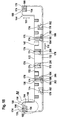
- the support element 136 On its underside 152, the support element 136 is likewise provided with a plurality of lower damping bumps 174 which taper downwardly from a base arranged on the underside 152 of the base body of the support element 136 and on each one transverse, preferably substantially perpendicular, to the vertical 154 extending support surface 176 ends.
- the lower damping bumps 174 have a substantially trapezoidal vertical cross-section.
- the long sides of the two lower central damping bumps 178 extend substantially parallel to the transverse direction 120.
- a lower intermediate damping bump 180 and a lower outer damping bump 182 follow each other on both sides of the lower middle damping bumps 178.
- Each of the lower intermediate damping bumps 180 comprises an inner portion 184, whose long sides are oriented substantially parallel to the transverse direction 120, and a shorter outer portion 186 immediately adjacent to the inner portion 184, the long sides of which are aligned substantially parallel to the longitudinal direction 116.
- Each of the lower outer damping bumps 182 is formed in an angular shape and thus extends in sections parallel to the longitudinal direction 116 and partially parallel to the transverse direction 120.
- a multi-stage damping bump group 188 is arranged, which as the first damping step a high damping hump 190 whose support surface 192 at rest H of the support member 136 (measured from the bottom 152 of the strip-shaped base body of the support member 136 from ), and as a second damping stage, a low damping hump 194, the support surface 196 in the resting state of the support member 136 at the height h, ie closer to the bottom 152 of the body of the Support member 136, from which extend the lower damping bumps 174 downwards, is located.
- the tips of the high damping bump 190 and the low damping bump 194 are separated by a gap 198 disposed between the two damping bumps and extending substantially parallel to the transverse direction 120 which decouples the two damping bumps 190, 194 so that the material of the high damping bump 190 can be deformed in the initial phase of a shock stress, without being hindered by a coupling to the material of the low damping bump 194.
- the gap 198 extends, starting from the support surface 196 of the low damper bump 194, by at least the height h / 2, preferably by approximately 70% of the height h, towards the bottom 152 of the base body of the support member 136.
- the bumps 190, 194 of the bump group 188 are interconnected by a common bump pad 200.
- the higher damping hump 190 is preferably located further from the center of the support member 136 than the lower damping hump 194 of the damping bump group 188.
- the support surfaces 192 of the high damper bumps 190 of the damper bump groups 188 are the support surfaces 176 of the lower outer damping bumps 182 and the support surfaces 202 of the outer portions 186 of the lower intermediate damping bumps 180, which are all at the same height H (measured from the underside 152 of the strip-shaped base of the support member 136), all at the interior of the 132 Umverpackung 110 facing top 204 of the respective associated inner closing tab 126 flat.
- the lower central damping bumps 178 and the inner portions 184 of the lower intermediate damping bumps 180 extend into the space 130 between the free edges 128 of the inner closure tabs 126 so that the support surfaces 206 of the lower middle damping bumps 178 and inner portions 184 of FIG lower intermediate damping bumps 180, which are all at the same height H '(as measured from the underside 152 of the strip-shaped base of the support member 136) farther from the bottom 152 of the support member 136 than the height H of the high damping bump support surface 192 190 of the damping bump groups 188 and the support surfaces 178 of the lower outer damping bumps 182, in the resting state of the package 100 lie flat against the upper surface 208 of one of the outer closing latches 124 of the folding box 112.
- the difference between the heights H on the one hand and H 'on the other hand corresponds to the thickness of the inner closing tabs 126, which corresponds to the material thickness of the folding box 112 of, for example, approximately 7 mm.
- the possible deflection of the packaged sink 102 is effectively reduced, especially in the particularly fracture-prone middle region of the sink, and thus the risk of breakage of the sink, in particular a sink made of a composite material, is considerably reduced in this area.
- recesses or depressions 210 are provided on the upper surface 148 of the support member 136 just vertically above the lower central damping bumps 178,180 formed to be complementary to the tips of the lower middle damping bumps 178 and the inner portions 184 of the lower intermediate damping bumps 180, respectively, and whose depth substantially matches the difference between the heights H and H 'of the lower damping bumps 174 so that all the lower damping bumps 174 flat against the top 148 of the lower, serving as a spacer member 140 support member 136 when another, serving as a receiving element 138 support member 136 is placed from above on this lower support member 136.
- the support elements 136 are preferably formed from a foamed plastic material, in particular from an expanded polystyrene material.
- the support elements 136 are further preferably each formed in one piece.
- the reaction force of the support element 136 is thus specifically reduced in this first damping stage in the end region of the support element 136, where the forces acting on the longest lever with respect to the particularly fracture-prone central region of the packaged sink 102, thereby causing the sink 102 at low drop heights with a lower deflection in the receiving channel 146 of the damping receiving element 138 dips.
- this lower deflection in the first damping stage the risk of breakage of the sink, in particular a sink made of a composite material, in the particularly fracture-prone middle region of the sink is considerably reduced (see FIG. 10).
- This second, harder cushioning stage benefits from the fact that the edge region of the packaged sink 102 in the first cushioning stage is more evenly submerged in the receiving channel 146 of the receiving member 138.
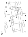
- the support elements 136 serving as receiving elements 138 of the above-described packaging 100 can be stacked directly on one another, the same receiving elements 138 can be used instead of for individual packaging a sink 102 in an outer package 110 can also be used to produce a stack 212 of rinses 102, as shown in FIG.
- two receiving elements 138 which are formed just like the support elements 136 described above, are pushed onto the edge sections of the rinsing edge of a first rinse 102a, so that these edge sections are received in the receiving channels 146 of the first receiving elements 138a ,
- the first receiving elements 138a can be fixed by means of a strapping of a strip material to the sink 102a.
- a second sink 102b is provided in the same way with second receiving elements 138b, which are identical to the first receiving elements 138a.
- These second receiving elements 138b can be fixed by means of a strapping of a strip material to the second sink 102b.
- the first sink 102a is placed on a base 214 in the head-facing, ie with downwardly facing pelvic openings, wherein the upper damping bumps 150 at the (in this position downwardly facing) top 148 of the first receiving elements 138a, the support surfaces 155 all the same Height, ie the same distance from the upper surface 148 of the strip-shaped main body of the receiving elements 138 a, are supported on the substrate 214 and the two first receiving elements 138 a carry the first sink 102 a, without the same touches the substrate 214.
- the second sink 102b is also placed in the head transfer, with the second receiving elements 138b on the first sink 102a, in such a way that the (in this position, facing downwards) upper damping bumps 150 of the second receiving elements 138b on the (in this position facing up) underside 152 of the first receiving elements 138a abut (and in this position upwardly facing) lower damping bumps 174 of the first receiving elements 138a flat against the (in this position facing down) top 148 of the second receiving elements 138b or engage in the recesses 210 at the top 148 of the second receiving elements 138b.
- the rinses 102 can be arranged in a particularly space-saving manner and stored in this arrangement, for example, before a single transport in an outer package 110.
- the rinses 102 stored in the stack 212 can be individually wrapped in a respective outer packaging without prior removal of the receiving elements 138 and thus particularly time-saving 100, so that the number of packaging elements required for storage in the stack 212 and for the subsequent individual packaging of the rinses 102 in each packaging 100 is reduced.
- a sink 102 with receiving elements 138 arranged thereon in the head transfer is also particularly suitable for transporting the sink 102 via a transport roller conveyor with transport rollers following one another in a conveying direction, which are rotatable about horizontal axes oriented perpendicular to the conveying direction.
- the sink 102 is turned off in the head-up with the receiving elements 138 on the transport roller track that the (in the head presentation facing down) upper damping bumps 150 rest on the upper crests of the transport rollers.
Landscapes
- Engineering & Computer Science (AREA)
- Mechanical Engineering (AREA)
- Buffer Packaging (AREA)
- Basic Packing Technique (AREA)
Abstract
Description
Die vorliegende Erfindung betrifft eine Verpackung für ein Transportgut, insbesondere eine Spüle, wobei die Verpackung mindestens einen Stützkörper umfasst, der mindestens einen Dämpfungshöcker aufweist.The present invention relates to a packaging for a cargo, in particular a sink, wherein the package comprises at least one support body having at least one damping hump.
Eine solche Verpackung ist beispielsweise aus der
Bei den bekannten Transportverpackungen kann eine zu große Krafteinleitung an den äußeren Endbereichen des Stützkörpers zum Bruch des Transportgutes, insbesondere der Spüle, im Mittelbereich des Transportgutes führen, wo sich insbesondere bei Spülen häufig die schwächste Stelle des Transportgutes befindet.In the known transport packaging can lead to a large force introduction to the outer end portions of the support body to break the cargo, in particular the sink, in the central region of the cargo, where in particular when flushing is often the weakest point of the cargo.
Der vorliegenden Erfindung liegt die Aufgabe zugrunde, eine Verpackung für ein Transportgut, insbesondere eine Spüle, der eingangs genannten Art zu schaffen, bei welcher die Einleitung von Stoßkräften an bestimmten Positionen des Transportguts noch besser gedämpft wird.The present invention has for its object to provide a package for a cargo, in particular a sink, of the type mentioned, in which the introduction of impact forces at certain positions of the cargo is even better damped.
Diese Aufgabe wird bei einer Verpackung für ein Transportgut mit den Merkmalen des Oberbegriffs von Anspruch 1 erfindungsgemäß dadurch gelöst, dass der Stützkörper mindestens eine mehrstufige Dämpfungshöckergruppe aufweist, die mindestens zwei Dämpfungshöcker umfasst, deren Abstützflächen auf unterschiedlichen Höhen liegen.This object is achieved in a package for a cargo with the features of the preamble of claim 1 according to the invention that the support body has at least one multi-stage Dämpfungshöckergruppe comprising at least two damping bumps whose support surfaces are at different heights.
Durch die Verwendung einer mindestens zweistufigen Dämpfungshöckergruppe statt eines einstufigen Dämpfungshöckers wird insbesondere bei kleineren vertikalen Stoßbeanspruchungen, beispielsweise beim Fall aus kleiner Fallhöhe (von beispielsweise höchstens ungefähr 30 cm), eine besonders schonende Dämpfung erreicht.By using an at least two-stage Dämpfungshöckergruppe instead of a single-stage Dämpfungshöckers is smaller, especially in smaller vertical impact stresses, for example in the case Drop height (for example, at most about 30 cm), achieved a particularly gentle damping.
Bei geringen Fallhöhen wird nämlich nur der höchste Dämpfungshöcker der Dämpfungshöckergruppe verformt, so dass die Reaktionskraft der Dämpfungshöckergruppe in einer ersten Dämpfungsstufe ganz gezielt reduziert wird, um die auf das Transportgut einwirkenden Kräfte und damit die Auslenkung und Durchbiegung des Transportguts in dieser ersten Dämpfungsstufe zu vermindern. Durch die geringere Durchbiegung in der ersten Dämpfungsstufe wird die Gefahr eines Bruchs des Transportguts, insbesondere einer Spüle aus einem Verbundwerkstoff, in dem besonders bruchanfälligen Mittelbereich der Spüle erheblich reduziert.At low drop heights, only the highest damping hump of the damping hump group is deformed, so that the reaction force of the damping hump group in a first damping step is deliberately reduced in order to reduce the forces acting on the cargo and thus the deflection and deflection of the transported material in this first damping step. Due to the lower deflection in the first damping stage, the risk of breakage of the cargo, in particular a sink made of a composite material, is significantly reduced in the particularly fracture-prone middle region of the sink.
Erst wenn die schwache Dämpfung durch den höchsten Dämpfungshöcker der Dämpfungshöckergruppe allein aufgezehrt ist und auch die Abstützfläche des nächst höheren Dämpfungshöckers der Dämpfungshöckergruppe der Stoßbeanspruchung ausgesetzt wird, setzt die zweite Dämpfungsstufe ein, welche eine härtere Dämpfung aufweist, da nunmehr zwei Dämpfungshöcker der Dämpfungshöckergruppe gleichzeitig verformt werden müssen.Only when the weak damping is consumed by the highest damping bump of the damping bump group alone and also the support surface of the next higher Dämpfungshöckers the Stoßungshöckergruppe is exposed to the impact, the second damping stage begins, which has a harder damping, since now two Dämpfungshöcker the Dämpfungshöckergruppe be deformed simultaneously have to.
Wenn die Dämpfungshöckergruppe noch weitere, niedrigere Dämpfungshöcker umfasst, so kann die Dämpfungshöckergruppe noch weitere Dämpfungsstufen aufweisen, welche jeweils einsetzen, wenn der nächsthöhere Dämpfungshöcker der Dämpfungshöckergruppe der Stoßbeanspruchung ausgesetzt wird.If the damping bump group comprises even more, lower damping bumps, then the damping bump group can have further damping stages, which are used in each case when the next higher damping bump of the damping bump group is exposed to the impact stress.
Durch die Verwendung einer mehrstufigen Dämpfungshöckergruppe wird ein dämpfendes Federsystem mit einem sehr gleichmäßigen Dämpfungsverlauf geschaffen, durch den besonders sensible Transportgüter, wie beispielsweise Verbundwerkstoffspülen, wirksam vor einem Bruch geschützt werden.By using a multi-stage damping bump group, a damping spring system with a very even damping curve created by the particularly sensitive cargo, such as composite rinse, effectively protected against breakage.
Unter der Höhe einer Abstützfläche eines Dämpfungshöckers ist der Abstand der betreffenden Abstützfläche von einem Grundkörper des Stützkörpers zu verstehen, von welchem aus der Dämpfungshöcker vorsteht.The height of a support surface of a damping bump is to be understood as meaning the distance of the relevant support surface from a base body of the support body from which the damping bump protrudes.
Die mindestens zwei Dämpfungshöcker der Dämpfungshöckergruppe können unmittelbar aneinander angrenzen.The at least two damping bumps of the damping bump group can adjoin one another directly.
Insbesondere kann vorgesehen sein, dass die Dämpfungshöcker der Dämpfungshöckergruppe einen gemeinsamen Dämpfungshöckersockel aufweisen.In particular, it can be provided that the damping bumps of the damping bump group have a common damping bump base.
Bei einer bevorzugten Ausgestaltung der Erfindung ist vorgesehen, dass die Dämpfungshöcker der Dämpfungshöckergruppe Dämpfungshöckerspitzen aufweisen, welche die Abstützflächen tragen und durch einen Spalt voneinander getrennt sind. Durch den Spalt zwischen den Dämpfungshöckerspitzen wird erreicht, dass die durch den Spalt voneinander getrennten Dämpfungshöcker voneinander entkoppelt sind, so dass das Material des höheren Dämpfungshöckers sich in einer ersten Dämpfungsstufe unter einer Stoßbeanspruchung verformen kann, ohne hieran durch eine Kopplung an das Material des jeweils niedrigeren Dämpfungshöckers gehindert zu sein.In a preferred embodiment of the invention, it is provided that the damping bumps of the damping bump group have damping bump tips, which support the support surfaces and are separated from one another by a gap. The gap between the cushion bumps ensures that the damping bumps separated from each other by the gap are decoupled from each other, so that the material of the higher cushion bump can deform under a shock load in a first damping stage without being coupled to the material of the lower one Damping bumps to be hindered.
Vorzugsweise erstreckt sich der Spalt, von den Abstützflächen der beiden durch den Spalt getrennten Dämpfungshöckerspitzen ausgehend, bis mindestens zur halben Höhe des niedrigsten Dämpfungshöckers der Dämpfungshöckergruppe.Preferably, the gap extends, starting from the support surfaces of the two damping bump tips separated by the gap, to at least half the height of the lowest damping bump of the damping bump group.
Damit die Dämpfungshöckergruppe die Wirkung eines mehrere zeitlich aufeinanderfolgenden Dämpfungsstufen durchlaufenden mehrstufigen Dämpfungselements und nicht die Wirkung einzelner, unabhängig voneinander wirkender Dämpfungselemente hat, ist es günstig, wenn der Abstand zwischen den Dämpfungshöckerspitzen der Dämpfungshöckergruppe kleiner ist als die Höhe des höchsten Dämpfungshöckers der Dämpfungshöckergruppe.In order for the damping bump group to have the effect of a multi-stage damping element passing several time-sequential damping stages and not the effect of individual, independently acting damping elements, it is favorable if the distance between the damping bump tips of the damping bump group is smaller than the height of the highest damping bump of the damping bump group.
Besonders günstig ist es, wenn der Abstand zwischen den Dämpfungshöckerspitzen der Dämpfungshöckergruppe kleiner ist als die Höhe des niedrigsten Dämpfungshöckers der Dämpfungshöckergruppe.It is particularly favorable if the distance between the damping bump tips of the damping bump group is smaller than the height of the lowest damping bump of the damping bump group.
Ferner hat es sich als günstig erwiesen, wenn der Abstand zwischen den Dämpfungshöckerspitzen der Dämpfungshöckergruppe kleiner ist als die größte Breite des breitesten Dämpfungshöckers der Dämpfungshöckergruppe.Further, it has been found to be beneficial if the distance between the bumps of the damping bump group is less than the largest width of the widest bump of the bump group.
Von Vorteil ist es, wenn der Abstand zwischen den Dämpfungshöckerspitzen der Dämpfungshöckergruppe höchstens ungefähr 15 cm, vorzugsweise höchstens ungefähr 5 cm, beträgt.It is advantageous if the distance between the damping bump tips of the damping bump group is at most about 15 cm, preferably at most about 5 cm.
Bei einer bevorzugten Ausgestaltung der Erfindung ist vorgesehen, dass der Stützkörper mindestens ein leistenförmiges Stützelement umfasst, dass sich in einer Längsrichtung von einem ersten Endbereich zu einem zweiten Endbereich erstreckt, wobei mindestens eine mehrstufige Dämpfungshöckergruppe in einem der Endbereiche des Stützelements angeordnet ist. Durch die Anordnung einer mehrstufigen Dämpfungshöckergruppe in einem Endbereich des Stützelements wird die Reaktionskraft des Stützelements bei einer Stoßbeanspruchung in der ersten Dämpfungsstufe ganz gezielt im Endbereich des Stützelements reduziert, wo die einwirkenden Kräfte den längsten Hebel in Bezug auf den besonders bruchanfälligen Mittelbereich des verpackten Transportguts aufweisen. Eine Verminderung der Dämpfungswirkung in der ersten Dämpfungsstufe ist also bei Anordnung der mehrstufigen Dämpfungshöckergruppe im Endbereich des Stützelements besonders wirksam.In a preferred embodiment of the invention it is provided that the support body comprises at least one strip-shaped support member extending in a longitudinal direction from a first end portion to a second end portion, wherein at least one multi-stage damping bump group is arranged in one of the end portions of the support member. By arranging a multi-stage damping bump group in an end region of the support element, the reaction force of the support element is reduced at a shock stress in the first damping stage quite deliberately in the end region of the support element, where the forces acting on the longest lever in Reference to the particularly fragile medium range of the packaged cargo. A reduction of the damping effect in the first damping stage is therefore particularly effective in the arrangement of the multi-stage damping hump group in the end region of the support element.
Unter dem Endbereich des Stützelements ist dabei in dieser Beschreibung und in den beigefügten Ansprüchen der Bereich des Stützelements zu verstehen, welcher sich von einem stirnseitigen Ende des Stützelements ausgehend über 20 % der Ausdehnung des Stützelements in seiner Längsrichtung erstreckt.In this description and in the appended claims, the end region of the support element is to be understood as the region of the support element which extends from an end-face end of the support element over 20% of the extent of the support element in its longitudinal direction.
Wenn das Stützelement an seinen stirnseitigen Enden quer zur Längsrichtung des Stützelements verlaufende Endabschnitte aufweist, so umfassen die Endbereiche des Stützelements insbesondere jeweils einen dieser Endabschnitte.If the support element has end sections extending transversely to the longitudinal direction of the support element at its front ends, the end regions of the support element in particular each include one of these end sections.
Besonders günstig ist es, wenn mindestens eine mehrstufige Dämpfungshöckergruppe in einem solchen Endabschnitt des Stützelements angeordnet ist.It is particularly favorable if at least one multi-stage damping bump group is arranged in such an end section of the support element.
Ferner ist vorzugsweise vorgesehen, dass in jedem der beiden Endbereiche des leistenförmigen Stützelements mindestens eine mehrstufige Dämpfungshöckergruppe angeordnet ist.Furthermore, it is preferably provided that at least one multi-stage damping hump group is arranged in each of the two end regions of the strip-shaped support element.
Insbesondere kann an jedem der beiden Endabschnitte eines leistenförmigen Stützelements mindestens eine mehrstufige Dämpfungshöckergruppe angeordnet sein.In particular, at least one multi-stage damping hump group can be arranged at each of the two end sections of a strip-shaped support element.
Um einen optimalen Dämpfungsverlauf der Dämpfungshöckergruppe zu erzielen, ist es von Vorteil, wenn der Abstand zwischen den Höhen der Abstützflächen der Dämpfungshöcker der Dämpfungshöckergruppe mindestens ungefähr 1 mm beträgt.In order to achieve an optimal damping characteristic of the damping bump group, it is advantageous if the distance between the heights of the support surfaces of the damping bumps of the damping bump group is at least approximately 1 mm.
Andererseits ist es von Vorteil, wenn der Abstand zwischen den Höhen der Abstützflächen der Dämpfungshöcker der Dämpfungshöckergruppe höchstens ungefähr 8 mm beträgt.On the other hand, it is advantageous if the distance between the heights of the support surfaces of the damping bumps of the damping bump group is at most about 8 mm.
Vorzugsweise wird der Abstand zwischen den Höhen der Abstützflächen umso größer gewählt, je kleiner die Abstützfläche des höheren Dämpfungshöckers ist und je leichter das Transportgut ist.Preferably, the distance between the heights of the support surfaces is chosen to be greater, the smaller the support surface of the higher damping bump and the lighter the cargo to be transported.
Bei einer bevorzugten Ausgestaltung der erfindungsgemäßen Verpackung ist vorgesehen, dass der Stützkörper mindestens ein leistenförmiges Stützelement umfasst, das sich in einer Längsrichtung des Transportguts, insbesondere der Spüle, erstreckt, und dass das Stützelement mindestens einen Dämpfungshöcker aufweist, der in der Längsrichtung des Stützelements eine größere Ausdehnung aufweist als in einer zur Längsrichtung des Stützelements und zur Vertikalen senkrechten Richtung. Ein solches Stützelement kann insbesondere beim Transport des Transportguts mittels einer Transportrollenbahn mit längs einer Förderrichtung der Transportrollenbahn aufeinanderfolgenden Transportrollen dazu dienen, zu verhindern, dass das Stützelement in den Zwischenraum aufeinanderfolgender Transportrollen gerät, wenn das Transportgut mit zur Förderrichtung der Transportrollenbahn paralleler Längsrichtung über die Transportrollenbahn gefördert wird.In a preferred embodiment of the packaging according to the invention it is provided that the support body comprises at least one strip-shaped support member which extends in a longitudinal direction of the transported material, in particular the sink, and in that the support element has at least one damping bump, which in the longitudinal direction of the support member has a larger Has expansion as in a direction perpendicular to the longitudinal direction of the support member and the vertical direction. Such a support element can in particular during transport of the cargo by means of a transport roller conveyor along a conveying direction of the transport roller conveyor successive transport rollers serve to prevent the support element in the space of successive transport rollers device when the transported conveyed with parallel to the conveying direction of the transport roller conveyor longitudinal direction over the transport roller conveyor becomes.
Wenn der Stützkörper mindestens ein leistenförmiges Stützelement umfasst, das sich in einer Längsrichtung des Transportguts, insbesondere einer Spüle, erstreckt, so weist das Stützelement vorzugsweise mindestens zwei einander benachbarte Dämpfungshöcker auf, die quer zu der Längsrichtung relativ zueinander versetzt sind. Durch diesen Versatz der Dämpfungshöcker relativ zueinander wird erreicht, dass diese Dämpfungshöcker auch dann, wenn sie relativ schmal ausgebildet sind, nicht in den Zwischenraum zwischen zwei in einer Förderrichtung aufeinanderfolgenden Rollen einer Transportrollenbahn geraten, wenn das Transportgut mit den daran angeordneten Stützelementen über die Transportrollenbahn gefördert wird, und zwar in einer solchen Ausrichtung, dass die Querrichtung des Transportguts parallel zur Förderrichtung der Transportrollenbahn verläuft.If the support body comprises at least one strip-shaped support element which extends in a longitudinal direction of the transport good, in particular a sink, extends, so the support member preferably has at least two adjacent damping bumps, which are offset transversely to the longitudinal direction relative to each other. By this offset of the damping bumps relative to each other is achieved that these damping bumps, even if they are relatively narrow, do not get into the space between two successive in a conveying direction roles of a transport roller conveyor when the transported transported with the support elements arranged thereon on the conveyor roller conveyor is, in such an orientation that the transverse direction of the transported material is parallel to the conveying direction of the transport roller conveyor.
Wenn ergänzend hierzu vorgesehen ist, dass die beiden einander benachbarten Dämpfungshöcker auch längs der Längsrichtung des Transportguts relativ zueinander versetzt sind, so wird hierdurch erreicht, dass die Dämpfungshöcker auch dann nicht in den Zwischenraum zwischen zwei aufeinanderfolgenden Rollen der Transportrollenbahn geraten, wenn das Transportgut in einer solchen Ausrichtung über die Transportrollenbahn gefördert wird, dass die Längsrichtung des Transportguts parallel zur Förderrichtung der Transportrollenbahn ausgerichtet ist.If, in addition to this, it is provided that the two mutually adjacent damping bumps are also offset relative to one another along the longitudinal direction of the transport good, this ensures that the damping bumps do not get into the space between two successive rollers of the transport roller track even if the transported goods are in one such orientation is promoted on the transport roller conveyor, that the longitudinal direction of the transported goods is aligned parallel to the conveying direction of the transport roller conveyor.
Bei einer bevorzugten Ausgestaltung der erfindungsgemäßen Verpackung ist vorgesehen, dass der Stützkörper mindestens ein Aufnahmeelement mit einem Aufnahmekanal für einen Randabschnitt des Transportguts, insbesondere einer Spüle, umfasst.In a preferred embodiment of the packaging according to the invention it is provided that the support body comprises at least one receiving element with a receiving channel for an edge portion of the transported material, in particular a sink.
In diesem Fall ist vorzugsweise mindestens eine mehrstufige Dämpfungshöckergruppe an dem mindestens einen Aufnahmeelement angeordnet.In this case, at least one multi-stage damping bump group is preferably arranged on the at least one receiving element.
Der Stützkörper der Verpackung kann grundsätzlich einstückig ausgebildet sein.The support body of the packaging can in principle be formed in one piece.
Bei einer bevorzugten Ausgestaltung der Erfindung ist vorgesehen, dass der Stützkörper mindestens ein separat von dem Aufnahmeelement ausgebildetes Distanzhalterelement, welches das Aufnahmeelement abstützt, umfasst. Da der Stützkörper der Verpackung in diesem Fall zwei separate Elemente umfasst, wird erreicht, dass Stoßbeanspruchungen sich nicht ungestört durch den gesamten Stützkörper hindurch ausbreiten können, wie dies bei einem einstückigen Stützkörper der Fall ist, sondern vielmehr durch den Übergang von dem einen Element zu dem anderen Element des Stützkörpers an der Kontaktfläche der Elemente eine zusätzliche Dämpfung von Stößen erfolgt.In a preferred embodiment of the invention it is provided that the support body comprises at least one separately formed by the receiving element spacer element which supports the receiving element comprises. Since the support body of the package in this case comprises two separate elements, it is achieved that impact stresses can not spread undisturbed through the entire support body, as is the case with a one-piece support body, but rather by the transition from the one element to the another element of the support body at the contact surface of the elements takes place an additional damping of shocks.
Zugleich wird die Dämpfungskapazität des Stützkörpers aufgrund des zusätzlichen Volumens des Distanzhalterelements gegenüber einem Stützkörper, welcher nur das Aufnahmeelement umfassen würde, erhöht.At the same time, the damping capacity of the support body is due to the additional volume of the spacer element relative to a support body, which would include only the receiving element increased.
In diesem Fall ist vorzugsweise mindestens eine mehrstufige Dämpfungshöckergruppe an dem mindestens einen Distanzhalterelement angeordnet.In this case, at least one multi-stage damping bump group is preferably arranged on the at least one spacer element.
Um die Anzahl der für die Verpackung benötigten, unterschiedlichen Elemente möglichst gering zu halten, ist es von Vorteil, wenn das Distanzhalterelement des Stützkörpers dieselbe Gestalt aufweist wie das Aufnahmeelement des Stützkörpers.In order to keep the number of required for the packaging, different elements as small as possible, it is advantageous if the spacer element of the support body has the same shape as the receiving element of the support body.
Bei einer bevorzugten Ausgestaltung der Erfindung ist vorgesehen, dass die Verpackung mindestens zwei Stützkörper umfasst, die jeweils mindestens ein Aufnahmeelement mit einem Aufnahmekanal für einen Randabschnitt des Transportguts und mindestens ein separat von dem Aufnahmeelement ausgebildetes Distanzhalterelement, welches das jeweils zugeordnete Aufnahmeelement abstützt, umfassen.In a preferred embodiment of the invention it is provided that the package comprises at least two support bodies, each having at least one receiving element with a receiving channel for a peripheral portion of Transport goods and at least one separately formed from the receiving element spacer element, which supports the respective associated receiving element include.
In diesem Fall ist es zur Reduktion der Anzahl der für die Verpackung benötigten unterschiedlichen Elemente von Vorteil, wenn die Aufnahmeelemente und die Distanzhalterelemente der mindestens zwei Stützkörper dieselbe Gestalt aufweisen.In this case, it is advantageous for reducing the number of different elements required for the packaging when the receiving elements and the spacer elements of the at least two supporting bodies have the same shape.
Bei einer besonders bevorzugten Ausgestaltung der Verpackung umfasst dieselbe zwei Stützkörper, welche insgesamt zwei Aufnahmeelemente und zwei Distanzhalterelemente umfassen, wobei alle vier dieser Elemente dieselbe Gestalt aufweisen, so dass alle diese Elemente innerhalb der Verpackung untereinander ausgetauscht werden können und nur ein Werkzeug zur Herstellung all dieser Elemente erforderlich ist.In a particularly preferred embodiment of the packaging, the same comprises two supporting bodies, which comprise a total of two receiving elements and two spacer elements, all four of these elements having the same shape, so that all these elements can be interchanged within the package and only one tool for producing all of these Elements is required.
Vorzugsweise sind die mindestens zwei Stützkörper der Verpackung an einander gegenüberliegenden Randabschnitten des Transportguts angeordnet.The at least two support bodies of the packaging are preferably arranged on mutually opposite edge sections of the transport good.
Die Verpackung umfasst vorzugsweise eine Umverpackung, deren Innenraum das Transportgut und den mindestens einen Stützkörper aufnimmt.The packaging preferably comprises an outer packaging whose interior receives the transported goods and the at least one support body.
Die Umverpackung kann insbesondere im wesentlichen quaderförmig ausgebildet sein.The outer packaging may in particular be formed substantially cuboid.
Ferner kann vorgesehen sein, dass die Umverpackung eine Faltkiste umfasst.Furthermore, it can be provided that the outer packaging comprises a folding box.
Im Ruhezustand der Verpackung, d.h. bei Abwesenheit von auf die Verpackung einwirkenden Stoßbelastungen, liegen vorzugsweise nur eine der Abstützflächen der Dämpfungshöcker der mehrstufigen Dämpfungshöckergruppe oder mehrere auf derselben Höhe liegende Abstützflächen der Dämpfungshöcker der mehrstufigen Dämpfungshöckergruppe an der Umverpackung an. Dadurch ist gewährleistet, dass bei Auftreten einer Stoßbeanspruchung zunächst nur die Dämpfungshöcker der ersten Dämpfungsstufe, deren Abstützflächen den größten Abstand von dem Grundkörper des Stützelements aufweisen, wirksam werden.At rest, the packaging, i. in the absence of shock loads acting on the packaging, preferably only one of the support surfaces of the damping bumps of the multi-stage damping bump group or a plurality of support surfaces of the damping bumps of the multi-stage damping bump group lying on the same height abut the outer packaging. This ensures that, when an impact stress occurs, only the damping bumps of the first damping stage, whose support surfaces have the greatest distance from the main body of the support element, become effective at first.
Ebenso ist es von Vorteil, wenn im Ruhezustand der Verpackung mindestens eine Abstützfläche eines Dämpfungshöckers der mehrstufigen Dämpfungshöckergruppe nicht an der Umverpackung anliegt. Dadurch ist gewährleistet, dass bei Auftreten einer Stoßbeanspruchung der betreffende Dämpfungshöcker noch nicht in der ersten Dämpfungsstufe, sondern erst in der zweiten oder gegebenenfalls einer weiteren Dämpfungsstufe verformt wird und somit zur Dämpfungswirkung der Dämpfungshöckergruppe beiträgt.Likewise, it is advantageous if at least one support surface of a damping bump of the multi-stage damping bump group does not bear against the outer packaging in the resting state of the packaging. This ensures that, when an impact stress occurs, the damping bump in question is not yet deformed in the first damping stage, but only in the second or optionally a further damping stage and thus contributes to the damping effect of the damping bump group.
Der Stützkörper der Verpackung ist vorzugsweise zumindest teilweise aus einem geschäumten Kunststoffmaterial gebildet. Hierdurch wird eine weitaus bessere Dämpfungswirkung erzielt als beispielsweise bei der Verwendung von Verpackungselementen aus Wellpappe.The support body of the packaging is preferably formed at least partially from a foamed plastic material. As a result, a much better damping effect is achieved than, for example, when using packaging elements made of corrugated cardboard.
Besonders günstig ist es, wenn der Stützkörper im wesentlichen vollständig aus einem geschäumten Kunststoffmaterial gebildet ist.It is particularly favorable when the support body is substantially completely formed from a foamed plastic material.
Ein besonders geeignetes geschäumtes Kunststoffmaterial ist expandiertes Polystyrol-Material.A particularly suitable foamed plastic material is expanded polystyrene material.
Die erfindungsgemäße Verpackung eignet sich insbesondere als Transportverpackung für besonders bruchempfindliche Transportgüter, insbesondere von besonders bruchempfindlichen Spülen, beispielsweise aus Keramik und/oder Verbundwerkstoffen.The packaging according to the invention is particularly suitable as a transport packaging for particularly fragile goods to be transported, in particular of particularly fragile rinses, for example made of ceramic and / or composite materials.
Die erfindungsgemäße Verpackung erlaubt es, das Transportgut besonders kostengünstig und prozesssicher zu verpacken.The packaging according to the invention makes it possible to pack the item to be transported in a particularly cost-effective and reliable manner.
Weitere Merkmale und Vorteile der Erfindung sind Gegenstand der nachfolgenden Beschreibung und der zeichnerischen Darstellung eines Ausführungsbeispiels.Further features and advantages of the invention are the subject of the following description and the drawings of an embodiment.
In den Zeichnungen zeigen:
- Fig. 1
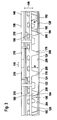
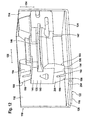
- eine teilweise geschnittene schematische perspektivische Darstellung einer Spülenverpackung, die eine als Faltkiste ausgebildete Umverpackung, zwei aus jeweils einem Aufnahmeelement und einem Distanzhalterelement gebildete Stützkörper und die verpackte Spüle umfasst;
- Fig. 2
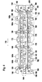
- eine der Fig. 1 entsprechende teilweise geschnittene schematische perspektivische Darstellung, wobei die verpackte Spüle entfernt worden ist;
- Fig. 3
- eine schematische Seitenansicht des Bereichs I aus Fig. 2;
- Fig. 4
- eine schematische Seitenansicht des Stützkörpers aus Fig. 2, ohne die Umverpackung, von einer der Spüle zugewandten Innenseite des Stützkörpers aus gesehen;
- Fig. 5
- eine vergrößerte Darstellung des Bereichs II aus Fig. 4;
- Fig. 6
- eine schematische perspektivische Ansicht eines Ausschnitts von Fig. 5;
- Fig. 7
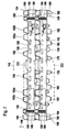
- eine schematische Seitenansicht des Stützkörpers aus Fig. 4, von einer der Spüle abgewandten Außenseite des Stützkörpers aus gesehen;
- Fig. 8
- eine vergrößerte Darstellung des Bereichs III aus Fig. 7;
- Fig. 9
- eine schematische perspektivische Darstellung eines Ausschnitts aus Fig. 8;
- Fig. 10
- eine vergrößerte Seitenansicht des linken Endbereichs des Distanzhalterelements des Stützkörpers aus Fig. 2, in einem unbelasteten Ruhezustand;
- Fig. 11
- eine der Fig. 10 entsprechende schematische Seitenansicht des linken Endbereichs des Distanzhalterelements des Stützkörpers, in einem Belastungszustand;
- Fig. 12
- eine schematische perspektivische Darstellung des linken Endbereichs des Distanzhalterelements des Stützkörpers, in einem unbelasteten Ruhezustand;
- Fig. 13
- eine teilweise geschnittene Seitenansicht eines Stapels aus zwei Spülen in der Kopfüberstellung, deren Randabschnitte in jeweils einem Aufnahmekanal eines Aufnahmeelements aufgenommen sind;
- Fig. 14
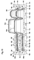
- eine schematische perspektivische Darstellung eines Stützelements (Aufnahmeelements oder Distanzelements) der Spülenverpackung, von oben und von der der Spüle abgewandten Außenseite des Stützelements aus gesehen;
- Fig. 15
- eine schematische Seitenansicht des Stützelements aus Fig. 14, von der der Spüle abgewandten Außenseite des Stützelements aus gesehen;
- Fig. 16
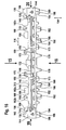
- eine schematische Seitenansicht des Stützelements aus Fig. 14, von der der Spüle zugewandten Innenseite des Stützelements aus gesehen;
- Fig. 17
- eine schematische Draufsicht von oben auf das Stützelement aus den Fig. 14 bis 16, mit der Blickrichtung in
Richtung des Pfeiles 15 in Fig. 16; - Fig. 18
- eine schematische Draufsicht von unten auf das Stützelement aus den Fig. 14 bis 17, mit der Blickrichtung in
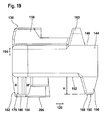
Richtung des Pfeiles 18 in Fig. 16; - Fig. 19
- eine schematische Draufsicht auf die linke Stirnseite des Stützelements aus den Fig. 14
bis 18, mit der Blickrichtung inRichtung des Pfeiles 19 in Fig. 16; - Fig. 20
- eine schematische Draufsicht auf die rechte Stirnseite des Stützelements aus den Fig. 14
bis 19, mit der Blickrichtung inRichtung des Pfeiles 20 in Fig. 16; und - Fig. 21
- eine vergrößerte Darstellung des Bereichs IV aus Fig. 18.
- Fig. 1
- a partially cut schematic perspective view of a sink package comprising a formed as a folding box outer packaging, two formed from a respective receiving element and a spacer element supporting body and the packaged sink;
- Fig. 2
- a corresponding partially sectioned schematic perspective view of Figure 1, wherein the packaged sink has been removed ..;
- Fig. 3
- a schematic side view of the area I of Fig. 2;
- Fig. 4
- a schematic side view of the support body of Figure 2, without the outer packaging, seen from one of the sink inside of the support body.
- Fig. 5
- an enlarged view of the area II of Fig. 4;
- Fig. 6
- a schematic perspective view of a section of Fig. 5;
- Fig. 7
- a schematic side view of the support body of Figure 4, seen from one of the sink outside of the support body.
- Fig. 8
- an enlarged view of the area III of Fig. 7;
- Fig. 9
- a schematic perspective view of a section of Fig. 8;
- Fig. 10
- an enlarged side view of the left end portion of the spacer element of the support body of Figure 2, in an unloaded resting state.
- Fig. 11
- one of Figure 10 corresponding schematic side view of the left end portion of the spacer element of the support body, in a loaded state;
- Fig. 12
- a schematic perspective view of the left end portion of the spacer element of the support body, in an unloaded resting state;
- Fig. 13
- a partially sectioned side view of a stack of two rinses in the head transfer, the edge portions are accommodated in a respective receiving channel of a receiving element;
- Fig. 14
- a schematic perspective view of a support element (receiving element or spacer element) of the sink packaging, seen from above and from the sink outside of the support member;
- Fig. 15
- a schematic side view of the support member of Figure 14, seen from the sink facing away from the outside of the support member.
- Fig. 16
- a schematic side view of the support member of Figure 14, seen from the sink facing the inside of the support member.
- Fig. 17
- a schematic plan view from above of the support member of FIGS. 14 to 16, with the viewing direction in the direction of the
arrow 15 in Fig. 16; - Fig. 18
- a schematic plan view from below of the support member of FIGS. 14 to 17, with the viewing direction in the direction of
arrow 18 in Fig. 16 .; - Fig. 19
- a schematic plan view of the left end side of the support member of FIGS. 14 to 18, with the viewing direction in the direction of
arrow 19 in Fig. 16 .; - Fig. 20
- a schematic plan view of the right end side of the support member of FIGS. 14 to 19, with the viewing direction in the direction of
arrow 20 in Fig. 16; and - Fig. 21
- an enlarged view of the area IV of FIG. 18.
Gleiche oder funktional äquivalente Elemente sind in allen Figuren mit denselben Bezugszeichen bezeichnet.Identical or functionally equivalent elements are denoted by the same reference numerals in all figures.
Eine in den Fig. 1 bis 12 dargestellte, als Ganzes mit 100 bezeichnete Verpackung für eine Spüle 102, die in dem dargestellten Ausführungsbeispiel ein Hauptbecken 104, ein Zusatzbecken 106 und einen auf der dem Zusatzbecken 106 abgewandten Seite des Hauptbeckens 104 angeordneten, flachen Abtropfbereich 108 aufweist, umfasst eine Umverpackung 110, die als eine Faltkiste 112, beispielsweise aus einem Wellpappenmaterial oder einem Kartonmaterial, ausgebildet ist.1 to 12, designated as a whole with 100 packaging for a
Die im wesentlichen quaderförmige Faltkiste umfasst zwei vertikale lange Seitenwände 114, die sich in einer Längsrichtung 116 der Verpackung 100 erstrecken, zwei vertikale kurze Seitenwände 118, die sich in einer senkrecht zur Längsrichtung 116 verlaufenden horizontalen Querrichtung 120 der Verpackung 100 erstrecken, einen Boden 122, der aus zwei an den langen Seitenwänden 114 der Faltkiste 112 klappbar angeordneten äußeren Schließlaschen 124 (von denen in den Figuren nur eine dargestellt ist) und zwei an den kurzen Seitenwänden 118 der Faltkiste 112 klappbar angeordneten inneren Schließlaschen 126 (von denen in den Figuren nur jeweils eine Hälfte dargestellt ist) gebildet ist, sowie einen (nicht dargestellten) Deckel, der ebenso wie der Boden 122 aus an den langen Seitenwänden 114 klappbar angeordneten äußeren Schließlaschen und an den kurzen Seitenwänden 118 klappbar angeordneten inneren Schließlaschen gebildet ist.The substantially parallelepiped folding box comprises two vertical
Wie aus den Fig. 1 bis 3 zu ersehen ist, stützen die inneren Schließlaschen 126 im eingeklappten Zustand die auf die Unterseite der inneren Schließlaschen 126 klappbaren äußeren Schließlaschen 124 der Faltkiste 112 ab, erstrecken sich aber von den kurzen Seitenwänden 118 der Faltkiste 112 nicht ganz bis zur Mitte der Faltkiste 112, so dass zwischen den im eingeklappten Zustand einander gegenüberstehenden freien Rändern 128 der beiden inneren Schließlaschen 126 des Bodens 122 ein Zwischenraum 130 verbleibt.As can be seen from FIGS. 1 to 3, support the
Im Innenraum 132 der Umverpackung 110 ist eine Stützanordnung für die verpackte Spüle 102 angeordnet, welche zwei einander gegenüberliegende Stützkörper 134 umfasst, zwischen denen die Spüle 102 gehalten ist, wobei in den Figuren nur einer der beiden (bezüglich der vertikalen Längsmittelebene der Verpackung 100 spiegelsymmetrisch zueinander ausgebildeten) Stützkörper 134 dargestellt ist.In the
Jeder der beiden Stützkörper 134 der Verpackung 100 umfasst zwei aufeinander angeordnete Stützelemente 136, nämlich ein Aufnahmeelement 138 und ein Distanzhalterelement 140, wobei das Aufnahmeelement 138 auf der Oberseite des Distanzhalterelements 140 aufliegt und das Aufnahmeelement 138 und das Distanzhalterelement 140 identische Gestalt und Ausrichtung aufweisen.Each of the two
Die beiden Stützkörper 134 der Verpackung 100 umfassen also insgesamt vier Stützelemente 136 von identischer Gestalt, nämlich zwei Aufnahmeelemente 138 und zwei Distanzhalterelemente 140.The two
Der Aufbau dieser vier identisch miteinander ausgebildeten Stützelemente 136 wird nachstehend am Beispiel des in den Fig. 14 bis 21 einzeln dargestellten Stützelements 136, welches in der Verpackung 100 als Aufnahmeelement 138 oder als Distanzhalterelement 140 dienen kann, im Detail beschrieben:The construction of these four
Das Stützelement 136 ist als eine im wesentlichen U-förmige Stützleiste ausgebildet, mit einem sich in der Längsrichtung 116 erstreckenden Mittelabschnitt 142 und zwei sich längs der Querrichtung 120 erstreckenden Endabschnitten 144.The
Wie am besten aus Fig. 16 zu ersehen ist, ist das Stützelement 136 mit einem Aufnahmekanal 146 versehen, der durch eine ungefähr mittig in horizontaler Richtung an den der Spüle 102 zugewandten Innenseiten des Mittelabschnitts 142 und der Endabschnitte 144 verlaufende Nut gebildet ist.As best seen in Figure 16, the
Dieser Aufnahmekanal 146 dient bei Verwendung des Stützelements 136 als Aufnahmeelement 138 zur Aufnahme eines der beiden langen Randabschnitte der Spüle 102, die sich parallel zu den beiden langen Seiten der Spüle 102 erstrecken, und jeweils eines Teils der beiden kurzen Randabschnitte, die sich längs der beiden kurzen Seiten der Spüle 102 erstrecken.This receiving
Beim Verpacken der Spüle 102 wird das als Aufnahmeelement 138 verwendete Stützelement 136 so auf den Spülenrand aufgeschoben, dass ein langer Randabschnitt des Spülenrandes in den Mittelabschnitt 142 des Aufnahmekanals 146 und Teile der kurzen Randabschnitte des Spülenrandes in die Endabschnitte 144 des Aufnahmekanals 146 eingreifen. Dabei liegt die Spüle 102 mit der Unterseite des Spülenrandes auf der unteren Begrenzungswand des Aufnahmekanals 146 auf.When packaging the
Ferner ist jedes Stützelement 136 an seiner Oberseite 148 mit einer Mehrzahl von oberen Dämpfungshöckern 150 versehen, mit denen sich das Stützelement 136 bei der Verwendung als Aufnahmeelement 138 an dem Deckel der Umverpackung 110 abstützt, während sich bei der Verwendung als Distanzhalterelement 140 das darüber angeordnete Aufnahmeelement 138 mit seiner Unterseite 152 an diesen oberen Dämpfungshöckern 150 abstützt.Further, each
Wie am besten aus den Fig. 14 und 15 zu ersehen ist, verjüngen sich die oberen Dämpfungshöcker 150 von ihrer an der Oberseite 148 des Grundkörpers des Stützelements 136 angeordneten Basis aus nach oben, so dass sie einen im wesentlichen trapezförmigen vertikalen Längsschnitt aufweisen und an jeweils einer quer, vorzugsweise im wesentlichen senkrecht zur Vertikalen 154 verlaufenden Abstützfläche 155 enden.As best seen in Figs. 14 and 15, the upper cushion bumps 150 taper upwardly from their base located at the top 148 of the body of the
Die Langseiten der oberen Dämpfungshöcker 150 sind bei den beiden oberen mittleren Dämpfungshöckern 156 und bei den beiden oberen äußeren Dämpfungshöckern 158, welche am Übergang zwischen dem Mittelabschnitt 142 und jeweils einem der Endabschnitte 144 des Stützelements 136 angeordnet sind, im wesentlichen parallel zur Querrichtung 120 ausgerichtet, während die Langseiten der an den Endabschnitten 144 angeordneten oberen endseitigen Dämpfungshöcker 160 und der jeweils paarweise zwischen jeweils einem oberen mittleren Dämpfungshöcker 156 und einem oberen äußeren Dämpfungshöcker 158 an dem Mittelabschnitt 142 angeordneten oberen Zwischen-Dämpfungshöcker 162 im wesentlichen parallel zur Längsrichtung 116 ausgerichtet sind.The long sides of the upper damping
Jedes Paar von oberen Zwischen-Dämpfungshöckern 162 umfasst jeweils einen an der der Spüle 102 abgewandten Außenseite des Stützelements 136 angeordneten äußeren Zwischen-Dämpfungshöcker 162a und einen an der der Spüle 102 zugewandten Innenseite der Stützelements 136 angeordneten inneren Zwischen-Dämpfungshöcker 162b.Each pair of upper intermediate damping
Wie am besten aus der Draufsicht der Fig. 17 zu ersehen ist, sind der äußere Zwischen-Dämpfungshöcker 162a und der jeweils zugeordnete innere Zwischen-Dämpfungshöcker 162b um mehr als die jeweiligen Höckerbreiten B, B' in der Querrichtung 120 gegeneinander versetzt. Durch diesen Versatz der Zwischen-Dämpfungshöcker 162 relativ zueinander wird erreicht, dass diese Dämpfungshöcker nicht in den Zwischenraum zwischen zwei in einer Förderrichtung aufeinanderfolgenden Rollen einer Transportrollenbahn geraten, wenn die Spüle 102 mit am Spülenrand angeordneten Aufnahmeelementen 138 in der Kopfüberstellung, d.h. mit nach unten weisenden oberen Dämpfungshöckern 150, über eine Transportrollenbahn gefördert wird, und zwar in einer solchen Ausrichtung, dass die Querrichtung 120 parallel zur Förderrichtung der Transportrollenbahn verläuft.As best seen in the plan view of FIG. 17, the outer
Ferner sind die beiden einander benachbart angeordneten Zwischen-Dämpfungshöcker 162 um ungefähr ihre Länge L bzw. L' in der Längsrichtung 116 gegeneinander versetzt. Durch diesen Versatz wird erreicht, dass die Dämpfungshöcker 162 nicht in den Zwischenraum zwischen zwei aufeinanderfolgenden Rollen der Transportrollenbahn geraten, wenn die Spüle 102 in einer solchen Ausrichtung über die Transportrollenbahn gefördert wird, dass die Längsrichtung 116 parallel zur Förderrichtung der Transportrollenbahn ausgerichtet ist.Furthermore, the two intermediate damping
Ferner wird dadurch, dass die beiden oberen Zwischen-Dämpfungshöcker 162 eines Zwischen-Dämpfungshöcker-Paares sowohl in der Längsrichtung 116 als auch in der Querrichtung 120 relativ zueinander versetzt sind, die Einleitung von Torsionskräften in das Stützelement 136 vermieden, so dass das Stützelement 136 bei den beim Transport der Spüle 102 auftretenden Kräften nicht von der Spüle 102 gelöst wird.Further, by making the two upper intermediate damping
Im Bereich der oberen äußeren Dämpfungshöcker 158 ist das Stützelement 136 an einer der Spüle 102 abgewandten Außenseite mit zwei Nuten 164 versehen, welche dazu dienen, jeweils ein (nicht dargestelltes) Umreifungsband einer Umreifung aufzunehmen, durch welche die Stützelemente 136 der beiden Stützkörper 134 oder aber, bei einem im folgenden noch näher erläuterten direkten Aufeinanderstapeln mehrerer Spülen 102, mehrere Aufnahmeelemente 138 verschiedener Spülen miteinander verbunden werden können.In the region of the upper outer damping
Die Nuten 164 sind mit einer optischen Markierung 166 in Form eines Quadratgitters versehen, welches anzeigt, wo an dem Stützelement 136 die Umreifungen verlaufen sollen.The
Die optischen Markierungen 166 können insbesondere als eine Oberflächenprofilierung, beispielsweise als in die Außenfläche des Stützelement 136 eingeformte Rillen, ausgebildet sein.The
Wie am besten aus Fig. 16 zu ersehen ist, ist das Stützelement 136 an seiner der Spüle 102 zugewandten Innenseite, beispielsweise an den Langseiten der inneren Zwischen-Dämpfungshöcker 162b, mit Prozesshilfskennzeichen 168 versehen, welche die Identifikation von zueinander gehörenden Verpackungsteilen beim Abpackprozess und bei der Qualitätssicherung erleichtern.As can best be seen from FIG. 16, the
Diese Prozesshilfskennzeichen 168 können beispielsweise die Form des Buchstabens A aufweisen.These process help tags 168 may be in the form of the letter A, for example.
Durch die Wahl eines Prozesshilfskennzeichens 168, welches bezüglich einer Spiegelung an der Horizontalen nicht symmetrisch ist, wird erreicht, dass die richtige Orientierung der Stützelemente 136 beim Abpackprozess der Spüle 102 anhand der Orientierung des Prozesshilfskennzeichens 168 überprüft werden kann.By selecting a
Die Prozesshilfskennzeichen 168 können beispielsweise als eine Oberflächenprofilierung, beispielsweise als in die Oberfläche des Stützelements 136 eingeformte Vertiefungen, ausgebildet sein.The
Ferner ist das Stützelement 136 an seiner der Spüle 102 zugewandten Innenseite im Bereich der oberen mittleren Dämpfungshöcker 156 mit jeweils einer vertikalen Aufnahmenut 170 versehen, welche dazu dienen kann, eine vertikale Halteplatte einer (nicht dargestellten) Beckenabdeckung der Spüle 102, die beispielsweise aus einer Kartonplatte oder einer Wellpappenplatte gebildet sein kann, aufzunehmen und so die Beckenabdeckung gegen eine Bewegung relativ zu dem Stützelement 136 in der Längsrichtung 116 zu sichern, wie dies in der
Außerdem ist das Stützelement 136 an seiner Oberseite 148 mit einem zwischen den oberen mittleren Dämpfungshöckern 156 angeordneten Anschlagblock 172 versehen, welcher in eine komplementäre Ausnehmung an einer (nicht dargestellten) horizontalen Abdeckplatte einer Beckenabdeckung eingreifen kann, um die horizontale Abdeckplatte gegen eine Verschiebung relativ zu dem Stützelement 136 in der Längsrichtung 116 zu sichern, wie dies ebenfalls in der
Ferner ist das Stützelement 136 an seiner der Spüle 102 zugewandten Innenseite, im Bereich zwischen den oberen mittleren Dämpfungshöckern 156 und den oberen Zwischen-Dämpfungshöckern 162, mit zwei vertikalen Aufnahmenuten 173 versehen, welche zur Aufnahme jeweils eines Vorsprungs an einem seitlichen Rand eines die beiden Stützkörper 134 miteinander verbindenden (nicht dargestellten) Zwischenelements dienen können, wie dies in der
An seiner Unterseite 152 ist das Stützelement 136 ebenfalls mit einer Mehrzahl von unteren Dämpfungshöckern 174 versehen, die sich von einer an der Unterseite 152 des Grundkörpers des Stützelements 136 angeordneten Basis aus nach unten verjüngen und an jeweils einer quer, vorzugsweise im wesentlichen senkrecht, zur Vertikalen 154 verlaufenden Abstützfläche 176 enden.On its
Die unteren Dämpfungshöcker 174 weisen einen im wesentlichen trapezförmigen vertikalen Querschnitt auf.The lower damping
Die Langseiten der beiden unteren mittleren Dämpfungshöcker 178 verlaufen im wesentlichen parallel zur Querrichtung 120.The long sides of the two lower central damping
Von jeweils einem unteren mittleren Dämpfungshöcker 178 aus in der Längsrichtung 116 längs des Mittelabschnitts 142 des Stützelements 136 voranschreitend, folgen zu beiden Seiten der unteren mittleren Dämpfungshöcker 178 jeweils ein unterer Zwischen-Dämpfungshöcker 180 und ein unterer äußerer Dämpfungshöcker 182 aufeinander.From a respective lower
Jeder der unteren Zwischen-Dämpfungshöcker 180 umfasst einen inneren Abschnitt 184, dessen Langseiten im wesentlichen parallel zur Querrichtung 120 ausgerichtet sind, und einen unmittelbar an den inneren Abschnitt 184 angrenzenden kürzeren äußeren Abschnitt 186, dessen Langseiten im wesentlichen parallel zur Längsrichtung 116 ausgerichtet sind.Each of the lower intermediate damping
Jeder der unteren äußeren Dämpfungshöcker 182 ist in Winkelform ausgebildet und erstreckt sich somit abschnittsweise parallel zur Längsrichtung 116 und abschnittsweise parallel zur Querrichtung 120.Each of the lower outer damping
An der Unterseite jedes Endabschnitts 144 des Stützelements 136 ist eine mehrstufige Dämpfungshöckergruppe 188 angeordnet, welche als erste Dämpfungsstufe einen hohen Dämpfungshöcker 190, dessen Abstützfläche 192 im Ruhezustand des Stützelements 136 auf der Höhe H (von der Unterseite 152 des leistenförmigen Grundkörpers des Stützelements 136 aus gemessen) liegt, und als zweite Dämpfungsstufe einen niedrigen Dämpfungshöcker 194, dessen Abstützfläche 196 im Ruhezustand des Stützelements 136 auf der Höhe h, d.h. näher an der Unterseite 152 des Grundkörpers des Stützelements 136, von welcher aus sich die unteren Dämpfungshöcker 174 nach unten erstrecken, liegt.On the underside of each
Die Spitzen des hohen Dämpfungshöckers 190 und des niedrigen Dämpfungshöckers 194 sind durch einen zwischen den beiden Dämpfungshöckern angeordneten und im wesentlichen parallel zur Querrichtung 120 verlaufenden Spalt 198 voneinander getrennt, welcher die beiden Dämpfungshöcker 190, 194 voneinander entkoppelt, so dass das Material des hohen Dämpfungshöckers 190 sich in der Anfangsphase einer Stoßbeanspruchung verformen kann, ohne hieran durch eine Kopplung an das Material des niedrigen Dämpfungshöckers 194 gehindert zu sein.The tips of the high damping
Der Spalt 198 erstreckt sich, ausgehend von der Abstützfläche 196 des niedrigen Dämpfungshöckers 194, um mindestens die Höhe h/2, vorzugsweise um ungefähr 70 % der Höhe h, nach oben in Richtung auf die Unterseite 152 des Grundkörpers des Stützelements 136 hin.The
Oberhalb des Spalts 198 sind die Dämpfungshöcker 190, 194 der Dämpfungshöckergruppe 188 durch einen gemeinsamen Dämpfungshöckersockel 200 miteinander verbunden.Above the
Der höhere Dämpfungshöcker 190 ist vorzugsweise weiter vom Mittelpunkt des Stützelements 136 entfernt angeordnet als der niedrigere Dämpfungshöcker 194 der Dämpfungshöckergruppe 188.The higher damping
Wie am besten aus den Fig. 3 und 10 zu ersehen ist, liegen im Ruhezustand der Verpackung 100, d.h. in einem Zustand, in welchem die Verpackung 100 keinen Stoßbelastungen ausgesetzt ist, die Abstützflächen 192 der hohen Dämpfungshöcker 190 der Dämpfungshöckergruppen 188, die Abstützflächen 176 der unteren äußeren Dämpfungshöcker 182 und die Abstützflächen 202 der äußeren Abschnitte 186 der unteren Zwischen-Dämpfungshöcker 180, welche sich alle auf derselben Höhe H (gemessen von der Unterseite 152 des leistenförmigen Grundkörpers des Stützelements 136) befinden, alle an der dem Innenraum 132 der Umverpackung 110 zugewandten Oberseite 204 der jeweils zugeordneten inneren Schließlasche 126 flächig an.As best seen in FIGS. 3 and 10, in the resting state of the
Hingegen erstrecken sich die unteren mittleren Dämpfungshöcker 178 sowie die inneren Abschnitte 184 der unteren Zwischen-Dämpfungshöcker 180 in den Zwischenraum 130 zwischen den freien Rändern 128 der inneren Schließlaschen 126 hinein, so dass die Abstützflächen 206 der unteren mittleren Dämpfungshöcker 178 und der inneren Abschnitte 184 der unteren Zwischen-Dämpfungshöcker 180, welche sich alle auf derselben Höhe H' (gemessen von der Unterseite 152 des leistenförmigen Grundkörpers des Stützelements 136) befinden, welche weiter von der Unterseite 152 des Stützelements 136 entfernt ist als die Höhe H der Abstützfläche 192 der hohen Dämpfungshöcker 190 der Dämpfungshöckergruppen 188 und der Abstützflächen 178 der unteren äußeren Dämpfungshöcker 182, im Ruhezustand der Verpackung 100 flächig an der Oberseite 208 einer der äußeren Schließlaschen 124 der Faltkiste 112 flächig anliegen.On the other hand, the lower central damping
Der Unterschied zwischen den Höhen H einerseits und H' andererseits entspricht der Dicke der inneren Schließlaschen 126, welche der Materialstärke der Faltkiste 112 von beispielsweise ungefähr 7 mm entspricht.The difference between the heights H on the one hand and H 'on the other hand corresponds to the thickness of the
Durch die Erhöhung der in den Zwischenraum 130 zwischen den freien Rändern 128 der inneren Schließlaschen 126 hinein ragenden unteren mittleren Dämpfungshöcker 178 und der inneren Abschnitte 184 der unteren Zwischen-Dämpfungshöcker 180 wird somit die an den freien Rändern 128 der inneren Schließlaschen 126 entstehende Stufe im Boden 122 der Faltkiste 112 ausgeglichen, wodurch eine stabile Abstützung des Stützkörpers 134 auf dem Boden 122 der Faltkiste 112 gewährleistet ist.By increasing in the
Ferner wird das Spiel zwischen dem Stützkörper 134 einerseits und dem Boden 122 der Faltkiste 112 andererseits im Bereich des Zwischenraums 130 zwischen den freien Rändern 128 der inneren Schließlaschen 126, vorzugsweise auf im wesentlichen Null, reduziert. Hierdurch wird die mögliche Auslenkung der verpackten Spüle 102 gerade im besonders bruchanfälligen Mittelbereich der Spüle wirksam verringert und somit die Gefahr eines Bruchs der Spüle, insbesondere einer Spüle aus einem Verbundwerkstoff, in diesem Bereich erheblich reduziert.Further, the play between the
Um zu ermöglichen, dass miteinander identische Stützelemente 136 trotz der Erhöhung der zentralen unteren Dämpfungshöcker 178, 180 stabil aufeinander gestapelt werden können, sind an der Oberseite 148 des Stützelements 136, genau vertikal über den unteren zentralen Dämpfungshöckern 178, 180, Ausnehmungen oder Vertiefungen 210 vorgesehen, die komplementär zu den Spitzen der unteren mittleren Dämpfungshöcker 178 bzw. der inneren Abschnitte 184 der unteren Zwischen-Dämpfungshöcker 180 ausgebildet sind und deren Tiefe im wesentlichen der Differenz zwischen den Höhen H und H' der unteren Dämpfungshöcker 174 entspricht, so dass alle unteren Dämpfungshöcker 174 flächig an der Oberseite 148 des unteren, als Distanzhalterelement 140 dienenden Stützelements 136 anliegen, wenn ein weiteres, als Aufnahmeelement 138 dienendes Stützelement 136 von oben auf dieses untere Stützelement 136 aufgesetzt wird.In order to enable mutually
Durch das Eingreifen der zentralen unteren Dämpfungshöcker 178, 180 des oberen Stützelements 136 in die Ausnehmungen 210 des unteren Stützelements 136 wird dabei ferner erreicht, dass die beiden aufeinandergestapelten Stützelemente 136 durch Formschluss gegen eine Relativverschiebung längs der Längsrichtung 116 gesichert sind.By engaging the central lower damping
Die Stützelemente 136 sind vorzugsweise aus einem geschäumten Kunststoffmaterial, insbesondere aus einem expandierten Polystyrol-Material, gebildet.The
Die Stützelemente 136 sind ferner vorzugsweise jeweils einstückig ausgebildet.The
Durch die Verwendung der zweistufigen Dämpfungshöckergruppen 188 an der Unterseite der Stützelemente 136 wird insbesondere bei kleineren vertikalen Stoßbeanspruchungen, insbesondere beim Fall aus kleiner Fallhöhe (von beispielsweise höchstens ungefähr 30 cm) eine besonders schonende Dämpfung erreicht.By using the two-stage damping
Dadurch, dass die Abstützfläche 196 des niedrigen Dämpfungshöckers 194 der Dämpfungshöckergruppe 188 im Ruhezustand der Verpackung um die Strecke H - h vom Boden 122 der Umverpackung 110 beabstandet ist, wird nämlich erreicht, dass bei geringen Fallhöhen (bis ungefähr 30 cm) nur der hohe Dämpfungshöcker 190 der Dämpfungshöckergruppe 188 verformt wird, ohne dass auch der niedrige Dämpfungshöcker 194 verformt und die Reaktionskraft des Stützelements 136 vergrößert wird. Die Reaktionskraft des Stützelements 136 wird also in dieser ersten Dämpfungsstufe ganz gezielt im Endbereich des Stützelements 136 reduziert, wo die einwirkenden Kräfte den längsten Hebel in Bezug auf den besonders bruchanfälligen Mittelbereich der verpackten Spüle 102 aufweisen, wodurch erreicht wird, dass die Spüle 102 bei geringen Fallhöhen mit einer geringeren Durchbiegung in den Aufnahmekanal 146 des dämpfenden Aufnahmeelements 138 eintaucht. Durch diese geringere Durchbiegung in der ersten Dämpfungsstufe wird die Gefahr eines Bruchs der Spüle, insbesondere einer Spüle aus einem Verbundwerkstoff, in dem besonders bruchanfälligen Mittelbereich der Spüle erheblich reduziert (siehe Fig. 10).The fact that the
Erst wenn die schwache Dämpfung durch den hohen Dämpfungshöcker 190 der Dämpfungshöckergruppe 188 allein aufgezehrt ist und auch die (größere) Abstützfläche 196 des niedrigen Dämpfungshöckers 194 der Dämpfungshöckergruppe 188 in Kontakt mit dem Boden 122 der Umverpackung 110 gelangt (siehe Fig. 11), setzt die zweite Dämpfungsstufe ein, welche härter ist, da nunmehr beide Dämpfungshöcker 190, 194 der Dämpfungshöckergruppe 188 gleichzeitig verformt werden müssen.Only when the weak damping is consumed by the high damping
Diese zweite, härtere Dämpfungsstufe profitiert davon, dass der Randbereich der verpackten Spüle 102 in der ersten Dämpfungsstufe gerader in den Aufnahmekanal 146 des Aufnahmeelements 138 eingetaucht ist.This second, harder cushioning stage benefits from the fact that the edge region of the packaged
Durch die Verwendung der mehrstufigen Dämpfungshöckergruppen 188 in den Endbereichen der Stützelemente 136 wird ein dämpfendes Federsystem mit einem sehr gleichmäßigen Dämpfungsverlauf geschaffen, durch den besonders sensible Produkte, wie beispielsweise Verbundwerkstoffspülen, wirksam vor einem Bruch geschützt werden.By using the multi-stage damping
Da die als Aufnahmeelemente 138 dienenden Stützelemente 136 der vorstehend beschriebenen Verpackung 100 direkt aufeinander stapelbar sind, können dieselben Aufnahmeelemente 138 statt zur Einzelverpackung jeweils einer Spüle 102 in einer Umverpackung 110 auch zur Herstellung eines Stapels 212 von Spülen 102 verwendet werden, wie er in Fig. 13 dargestellt ist.Since the
Zur Herstellung eines solchen Stapels 212 von Spülen 102 werden zwei Aufnahmeelemente 138, die genauso wie die vorstehend beschriebenen Stützelemente 136 ausgebildet sind, auf die Randabschnitte des Spülenrandes einer ersten Spüle 102a aufgeschoben, so dass diese Randabschnitte in den Aufnahmekanälen 146 der ersten Aufnahmeelemente 138a aufgenommen sind.To produce such a stack 212 of
Dabei können die ersten Aufnahmeelemente 138a mittels einer Umreifung aus einem Bandmaterial an der Spüle 102a festgelegt werden.In this case, the
Anschließend wird eine zweite Spüle 102b in derselben Weise mit zweiten Aufnahmeelementen 138b versehen, welche mit den ersten Aufnahmeelementen 138a identisch ausgebildet sind.Subsequently, a
Auch diese zweiten Aufnahmeelemente 138b können mittels einer Umreifung aus einem Bandmaterial an der zweiten Spüle 102b festgelegt werden.These second receiving
Anschließend wird die erste Spüle 102a in der Kopfüberstellung, d.h. mit nach unten weisenden Beckenöffnungen, auf einem Untergrund 214 abgestellt, wobei die oberen Dämpfungshöcker 150 an der (in dieser Stellung nach unten weisenden) Oberseite 148 der ersten Aufnahmeelemente 138a, deren Abstützflächen 155 alle dieselbe Höhe, d.h. denselben Abstand von der Oberseite 148 des leistenförmigen Grundkörpers der Aufnahmeelemente 138a, aufweisen, sich an dem Untergrund 214 abstützen und die beiden ersten Aufnahmeelemente 138a die erste Spüle 102a tragen, ohne dass dieselbe den Untergrund 214 berührt.Subsequently, the
Anschließend wird die zweite Spüle 102b ebenfalls in der Kopfüberstellung, mit den zweiten Aufnahmeelementen 138b voran auf die erste Spüle 102a aufgesetzt, und zwar so, dass die (in dieser Stellung nach unten weisenden) oberen Dämpfungshöcker 150 der zweiten Aufnahmeelemente 138b flächig an der (in dieser Stellung nach oben weisenden) Unterseite 152 der ersten Aufnahmeelemente 138a anliegen und die (in dieser Stellung nach oben weisenden) unteren Dämpfungshöcker 174 der ersten Aufnahmeelemente 138a flächig an der (in dieser Stellung nach unten weisenden) Oberseite 148 der zweiten Aufnahmeelemente 138b anliegen bzw. in die Vertiefungen 210 an der Oberseite 148 der zweiten Aufnahmeelemente 138b eingreifen.Subsequently, the
Auf die vorstehend beschriebene Weise können noch weitere Spülen 102, jeweils unter Verwendung eines Paares von Aufnahmeelementen 138, dem Spülenstapel 212 hinzugefügt werden.In the manner described above, further rinses 102, each using a pair of receiving
Hierdurch können die Spülen 102 besonders raumsparend angeordnet und in dieser Anordnung, beispielsweise vor einem Einzeltransport in einer Umverpackung 110, gelagert werden.In this way, the
Da für die Herstellung des Spülenstapels 212 dieselben Aufnahmeelemente 138 verwendet werden, wie sie auch als Bestandteile der Einzel-Verpackung 100 verwendet werden, können die in dem Stapel 212 gelagerten Spülen 102 ohne vorheriges Entfernen der Aufnahmeelemente 138 und somit besonders zeitsparend einzeln in jeweils eine Umverpackung 100 verpackt werden, so dass die Anzahl der für die Lagerung im Stapel 212 und für die anschließende Einzelverpackung der Spülen 102 in jeweils einer Verpackung 100 benötigten Verpackungselemente reduziert wird.Since the same receiving
Eine Spüle 102 mit daran angeordneten Aufnahmeelementen 138 in der Kopfüberstellung eignet sich auch insbesondere zum Transport der Spüle 102 über eine Transportrollenbahn mit längs einer Förderrichtung aufeinanderfolgenden Transportrollen, welche um senkrecht zur Förderrichtung ausgerichtete horizontale Achsen drehbar sind.A
Hierzu wird die Spüle 102 in der Kopfüberstellung mit den Aufnahmeelementen 138 so auf der Transportrollenbahn abgestellt, dass die (in der Kopfüberstellung nach unten weisenden) oberen Dämpfungshöcker 150 auf den oberen Kuppen der Transportrollen aufliegen.For this purpose, the
Durch die vorstehend beschriebene Gestaltung der oberen Dämpfungshöcker 150, insbesondere der Paare von oberen Zwischen-Dämpfungshöckern 162, der Aufnahmeelemente 138 wird dabei vermieden, dass diese Dämpfungshöcker beim Transport der Spüle 102 über die Transportrollenbahn in den Zwischenraum zwischen zwei aufeinanderfolgenden Transportrollen gelangen können.As a result of the design of the upper damping
Claims (31)
dadurch gekennzeichnet,
dass der Stützkörper (134) mindestens eine mehrstufige Dämpfungshöckergruppe (188) aufweist, die mindestens zwei Dämpfungshöcker (190, 194) umfasst, deren Abstützflächen (192, 196) auf unterschiedlichen Höhen (H, h) liegen.Packaging for a transport item, in particular a sink (102), comprising at least one support body (134) having at least one cushioning bump (174),
characterized,
in that the support body (134) has at least one multi-stage damping bump group (188) which comprises at least two damping bumps (190, 194) whose support surfaces (192, 196) are at different heights (H, h).
Applications Claiming Priority (1)
| Application Number | Priority Date | Filing Date | Title |
|---|---|---|---|
| DE102006021179A DE102006021179A1 (en) | 2006-05-06 | 2006-05-06 | Packaging e.g. for shipment, has sink and support, and damper with support has multi-damper that is included between two dampers and arranged at different heights |
Publications (3)
| Publication Number | Publication Date |
|---|---|
| EP1880950A2 true EP1880950A2 (en) | 2008-01-23 |
| EP1880950A3 EP1880950A3 (en) | 2009-05-27 |
| EP1880950B1 EP1880950B1 (en) | 2010-07-21 |
Family
ID=38564929
Family Applications (1)
| Application Number | Title | Priority Date | Filing Date |
|---|---|---|---|
| EP07004969A Not-in-force EP1880950B1 (en) | 2006-05-06 | 2007-03-10 | Packaging for cargo |
Country Status (3)
| Country | Link |
|---|---|
| EP (1) | EP1880950B1 (en) |
| AT (1) | ATE474776T1 (en) |
| DE (2) | DE102006021179A1 (en) |
Families Citing this family (3)
| Publication number | Priority date | Publication date | Assignee | Title |
|---|---|---|---|---|
| ATE531630T1 (en) * | 2009-01-14 | 2011-11-15 | Blanco Gmbh & Co Kg | PACKAGING FOR A SINK |
| DE102013019661A1 (en) * | 2013-11-19 | 2015-05-21 | Schock Gmbh | Tank transport unit, in particular sink transport unit |
| DE102022201516A1 (en) * | 2022-02-14 | 2023-08-17 | Blanco Gmbh + Co Kg | Packaging system for a transport good |
Citations (2)
| Publication number | Priority date | Publication date | Assignee | Title |
|---|---|---|---|---|
| EP1600401A1 (en) * | 2004-05-29 | 2005-11-30 | BLANCO GmbH + Co KG | Packaging for a sink |
| US20050263427A1 (en) * | 2004-05-29 | 2005-12-01 | Wolfgang Schneider | Packaging for a sink |
Family Cites Families (4)
| Publication number | Priority date | Publication date | Assignee | Title |
|---|---|---|---|---|
| IT1077140B (en) * | 1977-02-17 | 1985-05-04 | Eurodomestici Ind Riunite | PACKAGING FOR OBJECTS IN THE FORM OF A PARALLELEPIPED OR A CUBE, ESPECIALLY FOR DOMESTIC APPLIANCES |
| DE2845703C2 (en) * | 1978-10-20 | 1985-09-05 | Werzalit-Werke J.F. Werz KG, 7141 Oberstenfeld | One-piece single packaging base |
| KR0116756Y1 (en) * | 1995-07-31 | 1998-04-24 | 구자홍 | Shock absorbing structure for electronic products package |
| JP2000085848A (en) * | 1998-09-14 | 2000-03-28 | Sony Corp | Cushion for packaging box |
-
2006
- 2006-05-06 DE DE102006021179A patent/DE102006021179A1/en not_active Withdrawn
-
2007
- 2007-03-10 DE DE502007004453T patent/DE502007004453D1/en active Active
- 2007-03-10 AT AT07004969T patent/ATE474776T1/en active
- 2007-03-10 EP EP07004969A patent/EP1880950B1/en not_active Not-in-force
Patent Citations (2)
| Publication number | Priority date | Publication date | Assignee | Title |
|---|---|---|---|---|
| EP1600401A1 (en) * | 2004-05-29 | 2005-11-30 | BLANCO GmbH + Co KG | Packaging for a sink |
| US20050263427A1 (en) * | 2004-05-29 | 2005-12-01 | Wolfgang Schneider | Packaging for a sink |
Also Published As
| Publication number | Publication date |
|---|---|
| DE502007004453D1 (en) | 2010-09-02 |
| DE102006021179A1 (en) | 2007-11-08 |
| EP1880950A3 (en) | 2009-05-27 |
| EP1880950B1 (en) | 2010-07-21 |
| ATE474776T1 (en) | 2010-08-15 |
Similar Documents
| Publication | Publication Date | Title |
|---|---|---|
| EP2320157B1 (en) | Holder and modular stacking system for secure storage and/or transportation of frameless PV modules or other flat, cuboid bodies | |
| EP1710179A1 (en) | Store for stacks of crates | |
| EP1880950B1 (en) | Packaging for cargo | |
| EP2497727A2 (en) | Tray with folding support | |
| EP3009366B1 (en) | Transport container | |
| EP3608257A1 (en) | Packaging system for cargo and method for packaging cargo | |
| DE102004050197A1 (en) | Feeder for packing stacks of blister packs in cartons has dividers mounted on conveyor which fit against sides of stack, top cover fitting on stack which is made up of sections with gaps, through which dividers can pass | |
| WO2011054700A1 (en) | Transport device for containers, in particular for bottles | |
| EP1600403B1 (en) | Packing for a sink | |
| EP3406541B1 (en) | Package for objects | |
| EP1852358A1 (en) | Packaging for cargo | |
| EP1222043A1 (en) | Method for the production of lamella packets for adjustable steering columns | |
| EP1651533B1 (en) | Crate comprising multiple cavities | |
| DE102012011658A1 (en) | Cargo transport assembly for transporting pallets, has projecting portions and cavities with detachable connection to transmit torque between support beam and supporting portion | |
| EP3601077B1 (en) | Stackable storage rack | |
| EP3543158B1 (en) | Transport container | |
| DE202017100415U1 (en) | Foldable transport and storage device | |
| DE19948124A1 (en) | Stackable knock down container for bulk transportation and storage of fresh fruit, etc. | |
| EP2565130B1 (en) | Insert for a transport and storage container | |
| EP2036827B1 (en) | Stackable module tray | |
| DE202012002496U1 (en) | Packaging and cutting for this | |
| DE102020120245B4 (en) | Carrier for a motor vehicle | |
| DE102005055803B4 (en) | Device for removing a fuse element | |
| DE19620909A1 (en) | Collapsible platform based cargo carrier | |
| EP1842780A1 (en) | Packaging for cargo |
Legal Events
| Date | Code | Title | Description |
|---|---|---|---|
| PUAI | Public reference made under article 153(3) epc to a published international application that has entered the european phase |
Free format text: ORIGINAL CODE: 0009012 |
|
| AK | Designated contracting states |
Kind code of ref document: A2 Designated state(s): AT BE BG CH CY CZ DE DK EE ES FI FR GB GR HU IE IS IT LI LT LU LV MC MT NL PL PT RO SE SI SK TR |
|
| AX | Request for extension of the european patent |
Extension state: AL BA HR MK YU |
|
| PUAL | Search report despatched |
Free format text: ORIGINAL CODE: 0009013 |
|
| AK | Designated contracting states |
Kind code of ref document: A3 Designated state(s): AT BE BG CH CY CZ DE DK EE ES FI FR GB GR HU IE IS IT LI LT LU LV MC MT NL PL PT RO SE SI SK TR |
|
| AX | Request for extension of the european patent |
Extension state: AL BA HR MK RS |
|
| 17P | Request for examination filed |
Effective date: 20091103 |
|
| AKX | Designation fees paid |
Designated state(s): AT BE BG CH CY CZ DE DK EE ES FI FR GB GR HU IE IS IT LI LT LU LV MC MT NL PL PT RO SE SI SK TR |
|
| GRAP | Despatch of communication of intention to grant a patent |
Free format text: ORIGINAL CODE: EPIDOSNIGR1 |
|
| RIN1 | Information on inventor provided before grant (corrected) |
Inventor name: REITZIG, WOLFGANG |
|
| GRAS | Grant fee paid |
Free format text: ORIGINAL CODE: EPIDOSNIGR3 |
|
| GRAA | (expected) grant |
Free format text: ORIGINAL CODE: 0009210 |
|
| AK | Designated contracting states |
Kind code of ref document: B1 Designated state(s): AT BE BG CH CY CZ DE DK EE ES FI FR GB GR HU IE IS IT LI LT LU LV MC MT NL PL PT RO SE SI SK TR |
|
| REG | Reference to a national code |
Ref country code: GB Ref legal event code: FG4D Free format text: NOT ENGLISH |
|
| REG | Reference to a national code |
Ref country code: CH Ref legal event code: EP |
|
| REG | Reference to a national code |
Ref country code: IE Ref legal event code: FG4D |
|
| REF | Corresponds to: |
Ref document number: 502007004453 Country of ref document: DE Date of ref document: 20100902 Kind code of ref document: P |
|
| REG | Reference to a national code |
Ref country code: NL Ref legal event code: VDEP Effective date: 20100721 |
|
| LTIE | Lt: invalidation of european patent or patent extension |
Effective date: 20100721 |
|
| PG25 | Lapsed in a contracting state [announced via postgrant information from national office to epo] |
Ref country code: NL Free format text: LAPSE BECAUSE OF FAILURE TO SUBMIT A TRANSLATION OF THE DESCRIPTION OR TO PAY THE FEE WITHIN THE PRESCRIBED TIME-LIMIT Effective date: 20100721 Ref country code: FI Free format text: LAPSE BECAUSE OF FAILURE TO SUBMIT A TRANSLATION OF THE DESCRIPTION OR TO PAY THE FEE WITHIN THE PRESCRIBED TIME-LIMIT Effective date: 20100721 Ref country code: LT Free format text: LAPSE BECAUSE OF FAILURE TO SUBMIT A TRANSLATION OF THE DESCRIPTION OR TO PAY THE FEE WITHIN THE PRESCRIBED TIME-LIMIT Effective date: 20100721 |
|
| REG | Reference to a national code |
Ref country code: IE Ref legal event code: FD4D |
|
| PG25 | Lapsed in a contracting state [announced via postgrant information from national office to epo] |
Ref country code: IS Free format text: LAPSE BECAUSE OF FAILURE TO SUBMIT A TRANSLATION OF THE DESCRIPTION OR TO PAY THE FEE WITHIN THE PRESCRIBED TIME-LIMIT Effective date: 20101121 Ref country code: BG Free format text: LAPSE BECAUSE OF FAILURE TO SUBMIT A TRANSLATION OF THE DESCRIPTION OR TO PAY THE FEE WITHIN THE PRESCRIBED TIME-LIMIT Effective date: 20101021 Ref country code: CY Free format text: LAPSE BECAUSE OF FAILURE TO SUBMIT A TRANSLATION OF THE DESCRIPTION OR TO PAY THE FEE WITHIN THE PRESCRIBED TIME-LIMIT Effective date: 20100721 Ref country code: PL Free format text: LAPSE BECAUSE OF FAILURE TO SUBMIT A TRANSLATION OF THE DESCRIPTION OR TO PAY THE FEE WITHIN THE PRESCRIBED TIME-LIMIT Effective date: 20100721 Ref country code: PT Free format text: LAPSE BECAUSE OF FAILURE TO SUBMIT A TRANSLATION OF THE DESCRIPTION OR TO PAY THE FEE WITHIN THE PRESCRIBED TIME-LIMIT Effective date: 20101122 Ref country code: SI Free format text: LAPSE BECAUSE OF FAILURE TO SUBMIT A TRANSLATION OF THE DESCRIPTION OR TO PAY THE FEE WITHIN THE PRESCRIBED TIME-LIMIT Effective date: 20100721 |
|
| PG25 | Lapsed in a contracting state [announced via postgrant information from national office to epo] |
Ref country code: LV Free format text: LAPSE BECAUSE OF FAILURE TO SUBMIT A TRANSLATION OF THE DESCRIPTION OR TO PAY THE FEE WITHIN THE PRESCRIBED TIME-LIMIT Effective date: 20100721 Ref country code: SE Free format text: LAPSE BECAUSE OF FAILURE TO SUBMIT A TRANSLATION OF THE DESCRIPTION OR TO PAY THE FEE WITHIN THE PRESCRIBED TIME-LIMIT Effective date: 20100721 Ref country code: GR Free format text: LAPSE BECAUSE OF FAILURE TO SUBMIT A TRANSLATION OF THE DESCRIPTION OR TO PAY THE FEE WITHIN THE PRESCRIBED TIME-LIMIT Effective date: 20101022 |
|
| PG25 | Lapsed in a contracting state [announced via postgrant information from national office to epo] |
Ref country code: IE Free format text: LAPSE BECAUSE OF FAILURE TO SUBMIT A TRANSLATION OF THE DESCRIPTION OR TO PAY THE FEE WITHIN THE PRESCRIBED TIME-LIMIT Effective date: 20100721 Ref country code: DK Free format text: LAPSE BECAUSE OF FAILURE TO SUBMIT A TRANSLATION OF THE DESCRIPTION OR TO PAY THE FEE WITHIN THE PRESCRIBED TIME-LIMIT Effective date: 20100721 |
|
| PLBE | No opposition filed within time limit |
Free format text: ORIGINAL CODE: 0009261 |
|
| STAA | Information on the status of an ep patent application or granted ep patent |
Free format text: STATUS: NO OPPOSITION FILED WITHIN TIME LIMIT |
|
| PG25 | Lapsed in a contracting state [announced via postgrant information from national office to epo] |
Ref country code: RO Free format text: LAPSE BECAUSE OF FAILURE TO SUBMIT A TRANSLATION OF THE DESCRIPTION OR TO PAY THE FEE WITHIN THE PRESCRIBED TIME-LIMIT Effective date: 20100721 Ref country code: EE Free format text: LAPSE BECAUSE OF FAILURE TO SUBMIT A TRANSLATION OF THE DESCRIPTION OR TO PAY THE FEE WITHIN THE PRESCRIBED TIME-LIMIT Effective date: 20100721 Ref country code: SK Free format text: LAPSE BECAUSE OF FAILURE TO SUBMIT A TRANSLATION OF THE DESCRIPTION OR TO PAY THE FEE WITHIN THE PRESCRIBED TIME-LIMIT Effective date: 20100721 Ref country code: CZ Free format text: LAPSE BECAUSE OF FAILURE TO SUBMIT A TRANSLATION OF THE DESCRIPTION OR TO PAY THE FEE WITHIN THE PRESCRIBED TIME-LIMIT Effective date: 20100721 Ref country code: IT Free format text: LAPSE BECAUSE OF FAILURE TO SUBMIT A TRANSLATION OF THE DESCRIPTION OR TO PAY THE FEE WITHIN THE PRESCRIBED TIME-LIMIT Effective date: 20100721 |
|
| 26N | No opposition filed |
Effective date: 20110426 |
|
| PG25 | Lapsed in a contracting state [announced via postgrant information from national office to epo] |
Ref country code: ES Free format text: LAPSE BECAUSE OF FAILURE TO SUBMIT A TRANSLATION OF THE DESCRIPTION OR TO PAY THE FEE WITHIN THE PRESCRIBED TIME-LIMIT Effective date: 20101101 |
|
| REG | Reference to a national code |
Ref country code: DE Ref legal event code: R097 Ref document number: 502007004453 Country of ref document: DE Effective date: 20110426 |
|
| BERE | Be: lapsed |
Owner name: BLANCO G.M.B.H. + CO KG Effective date: 20110331 |
|
| PG25 | Lapsed in a contracting state [announced via postgrant information from national office to epo] |
Ref country code: MC Free format text: LAPSE BECAUSE OF NON-PAYMENT OF DUE FEES Effective date: 20110331 |
|
| REG | Reference to a national code |
Ref country code: CH Ref legal event code: PL |
|
| PG25 | Lapsed in a contracting state [announced via postgrant information from national office to epo] |
Ref country code: BE Free format text: LAPSE BECAUSE OF NON-PAYMENT OF DUE FEES Effective date: 20110331 Ref country code: MT Free format text: LAPSE BECAUSE OF FAILURE TO SUBMIT A TRANSLATION OF THE DESCRIPTION OR TO PAY THE FEE WITHIN THE PRESCRIBED TIME-LIMIT Effective date: 20100721 |
|
| PG25 | Lapsed in a contracting state [announced via postgrant information from national office to epo] |
Ref country code: CH Free format text: LAPSE BECAUSE OF NON-PAYMENT OF DUE FEES Effective date: 20110331 Ref country code: LI Free format text: LAPSE BECAUSE OF NON-PAYMENT OF DUE FEES Effective date: 20110331 |
|
| REG | Reference to a national code |
Ref country code: AT Ref legal event code: MM01 Ref document number: 474776 Country of ref document: AT Kind code of ref document: T Effective date: 20120310 |
|
| PG25 | Lapsed in a contracting state [announced via postgrant information from national office to epo] |
Ref country code: LU Free format text: LAPSE BECAUSE OF NON-PAYMENT OF DUE FEES Effective date: 20110310 |
|
| PG25 | Lapsed in a contracting state [announced via postgrant information from national office to epo] |
Ref country code: AT Free format text: LAPSE BECAUSE OF NON-PAYMENT OF DUE FEES Effective date: 20120310 |
|
| PG25 | Lapsed in a contracting state [announced via postgrant information from national office to epo] |
Ref country code: TR Free format text: LAPSE BECAUSE OF FAILURE TO SUBMIT A TRANSLATION OF THE DESCRIPTION OR TO PAY THE FEE WITHIN THE PRESCRIBED TIME-LIMIT Effective date: 20100721 |
|
| PG25 | Lapsed in a contracting state [announced via postgrant information from national office to epo] |
Ref country code: HU Free format text: LAPSE BECAUSE OF FAILURE TO SUBMIT A TRANSLATION OF THE DESCRIPTION OR TO PAY THE FEE WITHIN THE PRESCRIBED TIME-LIMIT Effective date: 20100721 |
|
| REG | Reference to a national code |
Ref country code: FR Ref legal event code: PLFP Year of fee payment: 9 |
|
| PGFP | Annual fee paid to national office [announced via postgrant information from national office to epo] |
Ref country code: FR Payment date: 20150309 Year of fee payment: 9 Ref country code: GB Payment date: 20150304 Year of fee payment: 9 |
|
| REG | Reference to a national code |
Ref country code: DE Ref legal event code: R082 Ref document number: 502007004453 Country of ref document: DE Representative=s name: HOEGER, STELLRECHT & PARTNER PATENTANWAELTE MB, DE |
|
| PGFP | Annual fee paid to national office [announced via postgrant information from national office to epo] |
Ref country code: DE Payment date: 20150429 Year of fee payment: 9 |
|
| REG | Reference to a national code |
Ref country code: DE Ref legal event code: R119 Ref document number: 502007004453 Country of ref document: DE |
|
| GBPC | Gb: european patent ceased through non-payment of renewal fee |
Effective date: 20160310 |
|
| REG | Reference to a national code |
Ref country code: FR Ref legal event code: ST Effective date: 20161130 |
|
| PG25 | Lapsed in a contracting state [announced via postgrant information from national office to epo] |
Ref country code: DE Free format text: LAPSE BECAUSE OF NON-PAYMENT OF DUE FEES Effective date: 20161001 Ref country code: GB Free format text: LAPSE BECAUSE OF NON-PAYMENT OF DUE FEES Effective date: 20160310 Ref country code: FR Free format text: LAPSE BECAUSE OF NON-PAYMENT OF DUE FEES Effective date: 20160331 |