EP1880879A1 - Pivotable towing device for traction vehicles - Google Patents
Pivotable towing device for traction vehicles Download PDFInfo
- Publication number
- EP1880879A1 EP1880879A1 EP07013337A EP07013337A EP1880879A1 EP 1880879 A1 EP1880879 A1 EP 1880879A1 EP 07013337 A EP07013337 A EP 07013337A EP 07013337 A EP07013337 A EP 07013337A EP 1880879 A1 EP1880879 A1 EP 1880879A1
- Authority
- EP
- European Patent Office
- Prior art keywords
- frame
- pull rod
- drawbar
- drive
- rotation
- Prior art date
- Legal status (The legal status is an assumption and is not a legal conclusion. Google has not performed a legal analysis and makes no representation as to the accuracy of the status listed.)
- Granted
Links
- 230000033001 locomotion Effects 0.000 claims abstract description 53
- 230000005540 biological transmission Effects 0.000 claims description 18
- 230000000903 blocking effect Effects 0.000 claims description 7
- 230000008878 coupling Effects 0.000 claims description 2
- 238000010168 coupling process Methods 0.000 claims description 2
- 238000005859 coupling reaction Methods 0.000 claims description 2
- 238000007598 dipping method Methods 0.000 claims description 2
- 230000008901 benefit Effects 0.000 description 4
- 239000002184 metal Substances 0.000 description 3
- 238000005096 rolling process Methods 0.000 description 3
- 229910000760 Hardened steel Inorganic materials 0.000 description 2
- 230000002349 favourable effect Effects 0.000 description 2
- 210000003746 feather Anatomy 0.000 description 2
- 229910000831 Steel Inorganic materials 0.000 description 1
- 238000010521 absorption reaction Methods 0.000 description 1
- 238000010276 construction Methods 0.000 description 1
- 230000000694 effects Effects 0.000 description 1
- 230000006872 improvement Effects 0.000 description 1
- 230000003993 interaction Effects 0.000 description 1
- 230000014759 maintenance of location Effects 0.000 description 1
- 230000007257 malfunction Effects 0.000 description 1
- 239000000463 material Substances 0.000 description 1
- 230000000149 penetrating effect Effects 0.000 description 1
- 230000009467 reduction Effects 0.000 description 1
- 239000010959 steel Substances 0.000 description 1
- 230000007704 transition Effects 0.000 description 1
- 230000001960 triggered effect Effects 0.000 description 1
- 238000011144 upstream manufacturing Methods 0.000 description 1
Images


Classifications
-
- B—PERFORMING OPERATIONS; TRANSPORTING
- B60—VEHICLES IN GENERAL
- B60D—VEHICLE CONNECTIONS
- B60D1/00—Traction couplings; Hitches; Draw-gear; Towing devices
- B60D1/48—Traction couplings; Hitches; Draw-gear; Towing devices characterised by the mounting
- B60D1/54—Traction couplings; Hitches; Draw-gear; Towing devices characterised by the mounting collapsible or retractable when not in use, e.g. hide-away hitches
Definitions
- the invention relates to a pivotable hitch for towing vehicles having the features in the preamble of the main claim.
- Such a pivotable hitch is from the EP 1 478 528 B1 known. It consists of a curved tie rod, which is mounted on two rotatory axes movable on a frame of the hitch.
- the towing device further comprises a mechanical drive for moving the drawbar between an operating position and a rest position, wherein the drive has a device for generating an at least partially superimposed rotational movement of the drawbar about both axes and a drive motor. The drive motor is moved during the pivoting movement of the drawbar.
- the invention solves this problem with the features in the main claim.
- the relatively stationary arrangement of the drive motor on the frame has several advantages. On the one hand, the routing and the control of the drive motor is simplified and improved. Furthermore, there is a more favorable drive kinematics and a lower construction cost. Suffice a single drive motor with a single and preferably rotating output shaft, which can be accommodated in a space-saving and protected in or on the housing of the drive device. The entire hitch can be smaller and easier and better to accommodate the towing vehicle. In addition, the device for generating the superimposed Rotational movement of the drawbar simplified and increased their reliability and accuracy.
- the preferred biaxial movement of the drawbar about rotational axes with motion superposition has advantages for the defined kinematics and the exact guidance of the pull rod movements as well as for operational safety and low wear.
- Favorable here is also the direct implementation of a rotating output movement of the drive in a preferably parallel-axis and in particular also rotating drawbar movement.
- a simplification and functional improvement also results for the device for locking the drawbar in one or both end positions.
- the anti-rotation device for the locking of the drawbar in the extended operating position can be simplified and improved.
- the claimed towing device also has the advantage that absorb the forces and loads acting in the towed operation on the extended drawbar better and more reliable and can be supported on the frame on the towing vehicle. Also, the kinematic assignment and the interaction of actuated in the Switzerlandstangen Gay drive parts are clear and are improved.
- FIG. 1 to 3 show a hitch (1) in different positions of movement and perspective views.
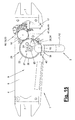
- FIG. 15 shows a variant of the towing device (1).
- the hitch (1) is arranged a towing vehicle, not shown, and housed hidden in a cavity of the vehicle rear, which sits on the underside of a rear opening.
- the hitch (1) has a preferably double or substantially U-shaped curved tie rod (11) at the free towering end of the rod neck (12) has a suitable traction head (15), for example a conventional ball head carries.
- the pull rod (11) is preferably made of metal, eg steel or light metal.
- the rod neck (12) goes after one first curvature (13) in an obliquely sloping back straight portion and then in a further and substantially straight rod end (14), which may be perpendicular or oblique. In the embodiment shown, all parts of the rod neck (12) have a common principal plane.
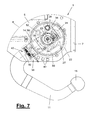
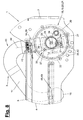
- the tie rod geometry is shown in FIGS. 7 and 8.
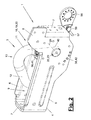
- Figures 1 and 15 show the operating position (2) of the hitch (1), in which the extended drawbar (11) occupies the prescribed positions and orientations and with its ball head (15) is ankuppelr positioned at a distance in front of the rear apron.
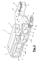
- Figures 2 and 3 show the retracted rest position (3) of the drawbar (11), in which it is aligned transversely to the vehicle longitudinal axis and with its curvature (13) facing upward.
- the ball bar (11) is e.g. mounted two-axis gimbal and has two substantially mutually perpendicular rotary and pivot axes (24,40). On translational axes or other additional axes for the Switzerlandstangenterrorism can be dispensed with.
- the drawbar (11) is reciprocated by a mechanical drive (16) between the operating position (2) and the rest position (3), wherein it preferably performs only rotational movements.
- the mechanical drive (16) is preferably a rotary drive with a rotating output shaft.
- the output shaft can run parallel to the pivot axis (24).
- the rotational movement of the output shaft can be converted directly into a rotational movement of the drawbar (11) about the pivot axis (24).
- the mechanical drive (16) has a device (19) for generating a rotational movement of the drawbar (11) superimposed at least in regions on its two rotational axes (24, 40). Furthermore, the mechanical drive (16) a drive motor (17) which acts on said means (19) and may be preferably designed as an electric motor, in particular as a geared motor with low voltage. It is stationary arranged on the hitch (1) and is supplied via a suitable cable connection from the power supply of the towing vehicle with operating voltage and control signals.
- the towing device (1) further has a controller, not shown, which is equipped with appropriate controls for positioning in the towing vehicle or connected to such possibly existing on the vehicle side controls.
- the towing device (1) can thereby be moved back and forth between its end positions (2, 3), with indicator lights or the like indicating the correct function or also malfunctions.
- the control may be from the vehicle interior, but alternatively also from the outside via a e.g. wireless remote control by radio, infrared or the like.
- a line connection with a socket may be present, which is arranged on a socket holder (55).
- the socket is supplied with the required operating voltage and signal or control voltages.
- the said currents or voltages at the socket in the rest position (3) can be switched off and switched to the operating position (2) via the central control of the hitch (1).
- the socket holder (55) is also moved and moved back and forth between a retracted rest position (3) and an extended operating position (2).
- the hitch (1) has a frame (4) which is e.g. is formed as a box-like housing, which surrounds an inner space (9) and is open at the top and bottom. In the free space (9), the pull rod (11) in the movement in the rest position (3) dip.
- the frame (4) consists e.g. of two frame walls (5, 6) oriented transversely to the vehicle longitudinal axis and to the pulling direction, which are e.g. form parallel side walls and at the ends via transverse end walls (7) are interconnected.
- the frame walls (5,6,7) thereby form a substantially ring-like or coat-like housing.
- Attachable side parts of the hitch may be attached to the end walls (7) for connection to the vehicle chassis, e.g. be screwed on.
- the frame (4) may consist of any suitable material. In the embodiment shown, it consists of two folded and substantially U-shaped metal sheets, which in the region of the end walls (7) connected in a suitable manner, e.g. riveted or screwed.
- a guide (10) for the here dipping and penetrating rod neck (12) may be present.
- the clear distance between the guide rails (10) may be smaller than the diameter of the pulling head (15), so that the guide strips (10) at the same time can form a ball stop (49) for the drawbar (11) in the rest position (3).
- the ball stop (49) may be part of a multi-part Verrieglungsvoriques (48), with the pull rod (11) defined in the various end positions and secured end positions can take.
- the ball stop (49) acts in conjunction with a force or torque shutdown of the drive motor (17) in conjunction with a self-locking of the drive.
- the device (19) for generating an at least partially superimposed rotational movement has a pivoting body (22) about a pivot bearing (23) about a transverse to the side walls (5,6) directed pivot axis (24) pivotally mounted on the frame (4) is.
- the pull rod (11) is rotatably mounted with its tie rod end (14) via a pivot bearing (39) about the axis of rotation (40).
- FIGS. 7 to 10 show this arrangement.
- the swivel body (22) is drivingly coupled to the drive motor (17).
- the device (19) has a gear (20) coupling the pivot axis (24) and the axis of rotation (40).
- the bearings (22,39) form the gimbal bearing of the drawbar (11) with the substantially perpendicular crossing rotary axes (24,40).
- the drawbar (11) can rotate about substantially 90 ° about the axis of rotation (40) and about a pivot angle of about 90 ° or more about the pivot axis (24), e.g. 150 ° to 190 °.
- the pull rod (11) is aligned in the rest position (3) along the frame (4) and immersed in the free space (9). In operating position (2), the pull rod (11) is aligned transversely to the frame (4) and substantially in the direction of travel and points with its curvature (13) downwards.
- the rotational movement of the drawbar (11) about the axis of rotation (40) is derived from the pivoting movement of the drawbar (11) or the pivoting body (22) about the pivot axis (24).
- the device (19) and the transmission (20) have a plurality of coupled transmission parts (21, 38). The pivoting movement and the rotational movement of the drawbar (11) overlap at least partially.
- the drive motor (17) may be formed as a geared motor in the aforementioned manner and may have an integrated or upstream reduction gearbox with an output member (18), e.g. is designed as a front-toothed flat output gear or pinion.
- the pinion (18) meshes with a drive element (30) which is e.g. is designed as a front-toothed and disc-shaped gear.
- the drive element (30) forms a first gear part (21), which is designed as a pivoting gear.
- the drive element (30) is rotationally connected to the swivel body (22) and at the same time is rotatably mounted on the swivel body (22).
- the drive element (30) has a driver (31) which acts sluggishly on a carrier element (34) arranged on the swivel body (22).
- the rotational movement of the drive element or toothed wheel (30) triggered by the drive motor (17) is transmitted in both directions of rotation to the swivel body (22) and carries it along.
- a subsequently explained freewheel (35) is provided, via which the drive element (30) with the pivoting body (22) is connected.
- the pivoting body (22) without the driving element or gear (30) is shown. It consists of a substantially cylindrical and the pivot axis (24) concentric housing (25) with two end bearing extensions to form the two-sided pivot bearing (23) on one or both side walls (5,6). On one end side, the housing (25) has a recessed guide track (27), which is bent concentrically to the pivot axis (24) and which is designed, for example, as a circular circumferential guide groove.
- the guide track (27) takes the side of the drive element (30) arranged driver (31) on. After the driver (31) performs only a limited arc angle about the pivot axis (24), the guide track (27) may have a correspondingly limited length.
- the entrainment element (34) is held against rotation and, e.g. held in a local transverse receiving opening (28).
- the entrainment element (34) is e.g. formed as a ball and can move in the receiving opening (28) transversely to the driving element (31) and substantially along the pivot axis (24).
- the entrainment element (34) can be part of a subsequently explained anti-rotation lock (50), which in turn can be part of a locking device (48).
- the drive motor (17) rotates the drive element (30) via the pinion (18), which rotates according to the translation about the pivot axis (24) and with its driver (31) the front side acting on the in the guideway (27) ball (34) acts.
- the ball (34) is fixed in this case in the transverse direction, so that the driver (31) abuts and transmits its rotary motion to the ball (34) and hereby takes the pivoting body (22) with the pull rod (11) in its rotational movement.
- the disc-shaped drive element (30) is sealed relative to the swivel body (22) and the guideway (27) and closes the guideway (27) to the outside.
- the drive element (30) and the pinion (18) are arranged on the inside of the frame (4) and close to its side wall (5).
- the drive element (30) can extend for storage purposes through the bearing-side opening in the side wall (5) and at the same time form the bearing eye for the swivel body (22). Possibly. the drive element (30) outside the side wall (5) widened again or with a cover provided according to Figure 1.
- the freewheel (35) is used to release an additional path of the drive element (30) relative to the standing in the end position or operating position (2) pivoting body (22) for the operation of the rotation lock (50).
- the freewheel (35) also serves for the entrainment of the pivoting body (22) during the reverse rotation of the drive (16,17).
- the freewheel (35) consists of a guide groove (36) bent concentrically with respect to the pivot axis (24) and a guide pin (37) which engages in a form-locking manner here.
- the guide pin (37) is associated with the pivoting body (22), wherein the guide groove (36) is located on the drive element (30). The arrangement can also be reversed.
- the arc length of the guide groove (36) is limited and corresponds to the arc path, the driver (31) for the locking function relative to the driving element (34) can perform.
- the drive element (30) with its guide groove (36) carries along the guide pin (37) abutting the rear groove end and thereby rotates the swivel body (22) in the direction of the arrow.
- the rotational movement is limited by the aforementioned ball stop (49).
- the rear rod end (14) is rotatably held and guided in the pivoting body (22) via the pivot bearing (39) about the axis of rotation (40).
- the drawbar (11) there may be an annular groove on the rod end (14) into which a support element (not shown) mounted on the housing (25) removably engages.
- the pull rod (11) enters the interior of the swivel body (22) via an opening in the housing jacket. As long as the pull rod (11) with its outwardly projecting rod neck (12) in the region of the frame (4), it is guided laterally on the guide rails (10).
- the second gear part (38) of the device (19) or the gear (20) is designed as a rotary gear and serves to rotate the pull rod (11) about its axis of rotation (40), which preferably takes place at the end of the pivoting movement of the swivel body (22) ,
- the transmission part (38) has two cooperating transmission elements (41, 42) on the pull rod (11) and on the frame (4).
- the one transmission element (41) on the pull rod (11) is e.g. as substantially rotationally fixed sprocket and the other gear member (42) on the frame (4) as a concentric to the pivot axis (24) curved series of wall openings.
- the assignment can also be reversed.
- the second transmission part (38) also has a trigger (43) which controls the engagement and function start of the rotary transmission (38) as a function of the pivoting position of the pivoting body (22).
- the trigger (43) has e.g. a rotatably connected to the pull rod (11) rotational driver (44) which cooperates with a frame-fixed stop (46).
- the sprocket (41) may be mounted elastically limited and have an effective on one or two sides resilient support (45), which optionally on the rotary driver (44) is supported.
- Figure 4 illustrates the function of the trigger (43).
- the pull rod (11) is rotated by a defined rotation angle of eg 90 ° and brought into the operating position (2) with longitudinal alignment to the vehicle longitudinal axis.
- the sprocket (41) may come in touching contact with the side wall (5) in the area between the relatively widely spaced teeth.
- the resilient support (45) provides for the occurrence of transverse forces on the tie rod (11) and in particular dynamic driving loads for a limited compliance of the drawbar (11) about the axis of rotation (40) and for a tolerable absorption of torsional forces in the rod neck (12).
- the rotation lock (50) consists of the aforementioned carrier element (34), for example a rolling element, in particular a ball, and a receiving trough (51) on the rod end (14) and a blocking element (52).
- a hardened steel support pin (29) may also be arranged to accommodate the high forces acting a hardened steel support pin (29), which may also have an adapted to the ball curvature axial guide trough for the ball (34).
- the receiving trough (51) is on the dimensions of Ball (34) tuned and may have a high strength and wear resistant insert made of hardened steel or the like.
- the receiving trough (51) is located in such a rotational position at the rod end (14), that the ball (34) can only enter the receiving trough (51) when the pull rod (11) pivoted out its operating position (2) and its local end position including the completed rotational movement about the rotation axis (40). Before this end position is reached, the ball (34) still supported on, for example cylindrical shell of the rod end (14) and can not perform any transverse movements and evasive movements with respect to the driver (31). Once the said end position (2) is reached and the swivel body (22) and the tie rod (11) can not rotate or pivot, which may also be limited by a stop and defined, the drive element (30) rotates over the freewheel (35) a little further.
- the driver (31) provided with a cam track (32) slides on the ball (34) and pushes it through the receiving opening (28) into the receiving recess or ball seat (51).
- the ball (34) pushes against the blocking element (52), which is e.g. is designed as a locking pin with a restoring spring (53) and pushes the locking pin (52) in a matching counter-opening (54) on the rear side wall (6) of the frame (4).
- the blocking element (52) is slidably guided and mounted in the swivel body (22) along the pivot axis (24).
- the drive motor (17) switches off again via a power or torque shutdown. Due to the self-locking of the swivel gear (21) this end position remains fixed.
- the locking pin (52) prevents a pivoting movement of the pivoting body (22) and the drawbar (11) about the pivot axis (24).
- the ball (34) blocked by the driver (31) on the rear side locks in turn via the positive reception in the ball seat (51) a rotational movement about the axis of rotation (40) so that the rod end (14) in the operating position (2) is firmly clamped.
- Any transverse forces introduced via the pulling head (15) can be absorbed non-destructively via internal deformations of the rod neck (12) and in particular torsional deformation of the end clamped rod end (14), whereby the rotary gear (38) is relieved via the above-mentioned resilient support (45).
- the cam track or cam track (32) of the driver (31) consists of a beveled front end with which the driver (31) engages obliquely over the ball (34) and projects it to swing the pull rod (11) can push or push to lock in the receiving opening (28).
- the cam track (32) may have at the top a step shape (33) consisting of several levels and stepped transitions arranged plateaus, which are aligned substantially transversely to the receiving opening (28) and to the direction of movement of the ball (34).
- the drive element (30) with the driver (31) rotates in the opposite direction and releases the ball (34), which under the restoring spring force of the locking pin (52) and by the backward movement of the rod end (14). about the axis of rotation (40) pushed out of the blocking position and then again on the jacket of the rod end (14) is supported.
- the pivot body (22) is taken, wherein the pull rod (11) via the rotary gear (38) rotates back to its initial position and in the rest position (3) is pivoted.
- socket holder (55) For actuating the movable and e.g. pivotally mounted on the frame (4) socket holder (55) may be arranged on the swivel body (22) a hook-shaped towed element (26) which entrains according to Figure 5 a driver (57) which is disposed beyond a pivot bearing (56) and against the resetting Effect of a spring (58) swings the socket holder (55) in the operating position (2).
- the spring (58) rotates the socket holder (55) when pivoting the pull rod (11) back into the rest position (3).
- Figure 15 shows a variant of the hitch (1) of Figure 1 to 5.
- the two embodiments are largely consistent with respect to the Glasstangenkinematik and the basic structural design.
- the variant of FIG. 15 has some design changes compared to the first embodiment.
- the front frame wall (5) is omitted for clarity and only the rear frame wall (6) shown, wherein the end walls (7) are formed and shown as folded wall profiles.
- the frame (4) can be connected to the vehicle body via one or both side walls (5, 6).
- the motor 17 is arranged inside the frame (4). He can have the illustrated vertical or vertical arrangement and drives via a correspondingly designed countershaft the output element (18), which according to the first embodiment of Figure 1 to 3 and trained is stored.
- FIG. 15 In the variant of Figure 15 are the receiving opening (28) and the driving element (34) in the operating position shown (2) below the pivot axis (24), wherein the other parts of the locking device (47), the ball stop (48) and the ball seat (50) are positioned differently according to.
- the receiving opening (28) and the driving element (34) above the pivot axis (24) are arranged.
- the embodiment of Figure 15 has advantages over the moment recording.
- the spring on the support (44) omitted in favor of a rigid support.
- the drawbar (11) or the drive device (1) perform lifting and lowering movements on the way between the rest and operating position, for example by the drive (16) and the device (19) with a common frame displaceable in the housing ( 4) are guided and the output axis of the drive (16) cooperates with a link, a rack or the like.
- the linear lifting and lowering movement for example, the linear lifting and lowering movement.
Abstract
Description
Die Erfindung betrifft eine schwenkbare Anhängevorrichtung für Zugfahrzeuge mit den Merkmalen im Oberbegriff des Hauptanspruchs.The invention relates to a pivotable hitch for towing vehicles having the features in the preamble of the main claim.
Eine solche schwenkbare Anhängevorrichtung ist aus der
Es ist Aufgabe der vorliegenden Erfindung, eine weiter verbesserte Anhängevorrichtung aufzuzeigen.It is an object of the present invention to provide a further improved hitch.
Die Erfindung löst diese Aufgabe mit den Merkmalen im Hauptanspruch.
Die relativ ortsfeste Anordnung des Antriebsmotors am Gestell hat verschiedene Vorteile. Einerseits wird die Leitungsführung und die Steuerung des Antriebsmotors vereinfacht und verbessert. Ferner ergeben sich eine günstigere Antriebskinematik und ein geringerer Bauaufwand. Es genügt ein einziger Antriebsmotor mit einer einzigen und bevorzugt drehenden Abtriebsachse, der platzsparend und geschützt in oder am Gehäuse der Antriebsvorrichtung untergebracht sein kann. Die gesamte Anhängevorrichtung kann kleiner bauen und lässt sich leichter und besser am Zugfahrzeug unterbringen. Zudem wird die Einrichtung zur Erzeugung der überlagerten Rotationsbewegung der Zugstange vereinfacht und deren Betriebssicherheit und Genauigkeit erhöht.The invention solves this problem with the features in the main claim.
The relatively stationary arrangement of the drive motor on the frame has several advantages. On the one hand, the routing and the control of the drive motor is simplified and improved. Furthermore, there is a more favorable drive kinematics and a lower construction cost. Suffice a single drive motor with a single and preferably rotating output shaft, which can be accommodated in a space-saving and protected in or on the housing of the drive device. The entire hitch can be smaller and easier and better to accommodate the towing vehicle. In addition, the device for generating the superimposed Rotational movement of the drawbar simplified and increased their reliability and accuracy.
Die bevorzugt zweiachsige Bewegung der Zugstange um rotatorische Achsen mit Bewegungsüberlagerung hat Vorteile für die definierte Kinematik und die exakte Führung der Zugstangenbewegungen sowie für die Betriebssicherheit und die Verschleißarmut. Günstig ist hierbei auch die direkte Umsetzung einer drehenden Abtriebsbewegung des Antriebs in eine bevorzugt parallelachsige und insbesondere ebenfalls drehende Zugstangenbewegung.The preferred biaxial movement of the drawbar about rotational axes with motion superposition has advantages for the defined kinematics and the exact guidance of the pull rod movements as well as for operational safety and low wear. Favorable here is also the direct implementation of a rotating output movement of the drive in a preferably parallel-axis and in particular also rotating drawbar movement.
Eine Vereinfachung und Funktionsverbesserung ergibt sich außerdem für die Vorrichtung zur Verriegelung der Zugstange in einer oder beiden Endstellungen. Insbesondere kann die Drehsicherung für die Verriegelung der Zugstange in der ausgefahrenen Betriebsstellung vereinfacht und verbessert werden.A simplification and functional improvement also results for the device for locking the drawbar in one or both end positions. In particular, the anti-rotation device for the locking of the drawbar in the extended operating position can be simplified and improved.
Die beanspruchte Anhängevorrichtung hat ferner den Vorteil, dass sich die im Anhängebetrieb auf die ausgefahrene Zugstange einwirkenden Kräfte und Belastungen besser und zuverlässiger aufnehmen und über das Gestell am Zugfahrzeug abstützen lassen. Auch die kinematische Zuordnung und das Zusammenwirken der bei der Zugstangenbewegung betätigten Antriebsteile sind eindeutiger und sind verbessert.The claimed towing device also has the advantage that absorb the forces and loads acting in the towed operation on the extended drawbar better and more reliable and can be supported on the frame on the towing vehicle. Also, the kinematic assignment and the interaction of actuated in the Zugstangenbewegung drive parts are clear and are improved.
In den Unteransprüchen sind weitere vorteilhafte Ausgestaltungen der Erfindung angebeben.In the subclaims further advantageous embodiments of the invention are given.
Die Erfindung ist in den Zeichnungen beispielsweise und schematisch dargestellt. Im einzelnen zeigen:
- Figur 1:
- eine perspektivische Darstellung der Anhängevorrichtung mit einer in Betriebsstellung ausgeschwenkten Zugstange,
- Figur 2:
- die Anhängevorrichtung von
Figur 1 in Ruhestellung mit eingeschwenkter Zugstange, - Figur 3:
- eine perspektivische Unteransicht der Anhängevorrichtung von
Figur 1, - Figur 4:
- eine teilweise aufgebrochene perspektivische Darstellung des mechanischen Antriebs und der Einrichtung zur Erzeugung einer zumindest bereichsweise überlagerten Rotationsbewegung der Zugstange,
- Figur 5:
- eine Darstellung der Anordnung von
Figur 4 in Frontansicht, - Figur 6:
- eine andere perspektivische Darstellung des Antriebs und der Einrichtung zur Erzeugung einer zumindest bereichsweise überlagerten Rotationsbewegung der Zugstange,
Figur 7 und 8:- eine teilweise abgebrochene Frontansicht der Anhängevorrichtung beim Einschwenken der Zugstange und in Ruhestellung,
Figur 9 und 10:- eine teilweise geschnittene Draufsicht auf die Anhängevorrichtung und deren Verriegelungsvorrichtung in zwei Funktionszuständen,
Figur 11 und 12:- eine teilweise abgebrochene Frontansicht der Anhängevorrichtung und der Verriegelungsvorrichtung in den beiden Funktionsstellungen entsprechend
Figur 9 und 10, - Figur 13:
- eine perspektivische Ansicht eines Treibelements
- Figur 14:
- einen Längsschnitt durch einen Mitnehmer am Treibelement und
- Figur 15:
- eine Variante der Anhängevorrichtung von
Figur 1 in teilweise aufgebrochener Frontansicht.
- FIG. 1:
- a perspective view of the hitch with a pivoted in operating position pull rod,
- FIG. 2:
- the towing device of Figure 1 in the rest position with pivoted drawbar,
- FIG. 3:
- 3 is a bottom perspective view of the hitch of FIG. 1;
- FIG. 4:
- a partially broken perspective view of the mechanical drive and the means for generating an at least partially superimposed rotational movement of the pull rod,
- FIG. 5:
- a representation of the arrangement of Figure 4 in front view,
- FIG. 6:
- another perspective view of the drive and the means for generating an at least partially superimposed rotational movement of the drawbar,
- FIGS. 7 and 8:
- a partially broken front view of the hitch when pivoting the drawbar and at rest,
- FIGS. 9 and 10:
- a partially sectioned plan view of the hitch and its locking device in two functional states,
- FIGS. 11 and 12:
- 2 is a partially broken front view of the hitch and the locking device in the two functional positions corresponding to Figure 9 and 10,
- FIG. 13:
- a perspective view of a driving element
- FIG. 14:
- a longitudinal section through a driver on the drive element and
- FIG. 15:
- a variant of the hitch of Figure 1 in a partially broken front view.
Figur 1 bis 3 zeigen eine Anhängevorrichtung (1) in verschiedenen Bewegungsstellungen und perspektivischen Ansichten. In Figur 15 ist eine Variante der Anhängevorrichtung (1) dargestellt.Figures 1 to 3 show a hitch (1) in different positions of movement and perspective views. FIG. 15 shows a variant of the towing device (1).
Die Anhängevorrichtung (1) ist einem nicht dargestellten Zugfahrzeug angeordnet und in einem Hohlraum des Fahrzeughecks verborgen untergebracht, welcher an der Unterseite einer Hecköffnung sitzt. Die Anhängevorrichtung (1) hat eine vorzugsweise zweifach oder im wesentlichen U-förmig gekrümmte Zugstange (11), die am freien hochragenden Ende des Stangenhalses (12) einen geeigneten Zugkopf (15), z.B. einen üblichen Kugelkopf, trägt. Die Zugstange (11) besteht vorzugsweise aus Metall, z.B. Stahl oder Leichtmetall. Der Stangenhals (12) geht nach einer ersten Krümmung (13) in einem schräg nach hinten abfallenden geraden Abschnitt und dann in ein weiteres und im wesentlichen gerades Stangenende (14) über, welches senkrecht oder schräg stehen kann. In der gezeigten Ausführungsform haben alle Teile des Stangenhalses (12) eine gemeinsame Hauptebene. Die Zugstangengeometrie ist in Figur 7 und 8 ersichtlich.The hitch (1) is arranged a towing vehicle, not shown, and housed hidden in a cavity of the vehicle rear, which sits on the underside of a rear opening. The hitch (1) has a preferably double or substantially U-shaped curved tie rod (11) at the free towering end of the rod neck (12) has a suitable traction head (15), for example a conventional ball head carries. The pull rod (11) is preferably made of metal, eg steel or light metal. The rod neck (12) goes after one first curvature (13) in an obliquely sloping back straight portion and then in a further and substantially straight rod end (14), which may be perpendicular or oblique. In the embodiment shown, all parts of the rod neck (12) have a common principal plane. The tie rod geometry is shown in FIGS. 7 and 8.
Figur 1 und 15 zeigen die Betriebsstellung (2) der Anhängevorrichtung (1), in der die ausgefahrene Zugstange (11) die vorbeschriebenen Stellungen und Ausrichtungen einnimmt und mit ihrem Kugelkopf (15) ankuppelbereit mit Abstand vor der Heckschürze positioniert ist. Figur 2 und 3 zeigen die eingefahrene Ruhestellung (3) der Zugstange (11), in der sie quer zur Fahrzeuglängsachse ausgerichtet ist und mit ihrer Krümmung (13) nach oben weist.Figures 1 and 15 show the operating position (2) of the hitch (1), in which the extended drawbar (11) occupies the prescribed positions and orientations and with its ball head (15) is ankuppelbereit positioned at a distance in front of the rear apron. Figures 2 and 3 show the retracted rest position (3) of the drawbar (11), in which it is aligned transversely to the vehicle longitudinal axis and with its curvature (13) facing upward.
Die Kugelstange (11) ist z.B. zweiachsig kardanisch gelagert und besitzt zwei im wesentlichen senkrecht aufeinander stehende Dreh- und Schwenkachsen (24,40). Auf translatorische Achsen oder weitere Zusatzachsen für die Zugstangenbewegung kann verzichtet werden. Die Zugstange (11) wird von einem mechanischen Antrieb (16) zwischen der Betriebsstellung (2) und der Ruhestellung (3) hin und her bewegt, wobei sie bevorzugt nur Drehbewegungen ausführt.The ball bar (11) is e.g. mounted two-axis gimbal and has two substantially mutually perpendicular rotary and pivot axes (24,40). On translational axes or other additional axes for the Zugstangenbewegung can be dispensed with. The drawbar (11) is reciprocated by a mechanical drive (16) between the operating position (2) and the rest position (3), wherein it preferably performs only rotational movements.
Der mechanische Antrieb (16) ist bevorzugt ein Drehantrieb mit einer drehenden Abtriebsachse. Die Abtriebsachse kann parallel zur Schwenkachse (24) verlaufen. Die Drehbewegung der Abtriebsachse kann direkt in eine Rotationsbewegung der Zugstange (11) um die Schwenkachse (24) umgesetzt werden.The mechanical drive (16) is preferably a rotary drive with a rotating output shaft. The output shaft can run parallel to the pivot axis (24). The rotational movement of the output shaft can be converted directly into a rotational movement of the drawbar (11) about the pivot axis (24).
Der mechanische Antrieb (16) weist eine Einrichtung (19) zur Erzeugung einer zumindest bereichsweise überlagerten Rotationsbewegung der Zugstange (11) um ihre beiden rotatorischen Achsen (24,40) auf. Ferner umfasst der mechanische Antrieb (16) ein Antriebsmotor (17), der auf die besagte Einrichtung (19) einwirkt und vorzugsweise als Elektromotor, insbesondere als Getriebemotor mit Niederspannung ausgebildet sein kann. Er ist stationär an der Anhängevorrichtung (1) angeordnet und wird über eine geeignete Kabelanbindung von der Stromversorgung des Zugfahrzeugs mit Betriebsspannung und Steuersignalen versorgt.The mechanical drive (16) has a device (19) for generating a rotational movement of the drawbar (11) superimposed at least in regions on its two rotational axes (24, 40). Furthermore, the mechanical drive (16) a drive motor (17) which acts on said means (19) and may be preferably designed as an electric motor, in particular as a geared motor with low voltage. It is stationary arranged on the hitch (1) and is supplied via a suitable cable connection from the power supply of the towing vehicle with operating voltage and control signals.
Die Anhängevorrichtung (1) besitzt ferner eine nicht dargestellte Steuerung, die mit entsprechenden Bedienelementen für die Positionierung im Zugfahrzeug ausgerüstet oder mit solchen ggf. fahrzeugseitig bereits vorhandenen Bedienelementen verbunden ist. Die Anhängevorrichtung (1) kann hierdurch zwischen ihren Endstellungen (2,3) hin und her bewegt werden, wobei Kontrollleuchten oder dergl. die korrekte Funktion oder auch Fehlfunktionen anzeigen. Die Steuerung kann vom Fahrzeuginnenraum, alternativ aber auch von außen über eine z.B. drahtlose Fernbedienung per Funk, Infrarot oder dergl. betätigt werden.The towing device (1) further has a controller, not shown, which is equipped with appropriate controls for positioning in the towing vehicle or connected to such possibly existing on the vehicle side controls. The towing device (1) can thereby be moved back and forth between its end positions (2, 3), with indicator lights or the like indicating the correct function or also malfunctions. The control may be from the vehicle interior, but alternatively also from the outside via a e.g. wireless remote control by radio, infrared or the like.
Ferner kann eine Leitungsverbindung mit einer Steckdose (nicht dargestellt).vorhanden sein, die an einem Steckdosenhalter (55) angeordnet ist. Der Steckdose werden die erforderliche Betriebsspannung sowie Signal- oder Steuerspannungen zugeleitet. Über die zentrale Steuerung der Anhängevorrichtung (1) können hierbei die genannten Ströme oder Spannungen an der Steckdose in Ruhestellung (3) abgeschaltet und in Betriebsstellung (2) aufgeschaltet werden. Bei den Schwenkbewegungen der Zugstange (11) wird auch der Steckdosenhalter (55) mitbewegt und zwischen einer zurückgezogenen Ruhestellung (3) und einer ausgefahrenen Betriebsstellung (2) hin und her bewegt.Further, a line connection with a socket (not shown) may be present, which is arranged on a socket holder (55). The socket is supplied with the required operating voltage and signal or control voltages. In this case, the said currents or voltages at the socket in the rest position (3) can be switched off and switched to the operating position (2) via the central control of the hitch (1). During the pivoting movements of the pull rod (11), the socket holder (55) is also moved and moved back and forth between a retracted rest position (3) and an extended operating position (2).
Die Anhängevorrichtung (1) besitzt ein Gestell (4), welches z.B. als ein kastenartiges Gehäuse ausgebildet ist, welches einen innenliegenden Freiraum (9) umgibt und nach oben und unten offen ist. In den Freiraum (9) kann die Zugstange (11) bei der Bewegung in die Ruhestellung (3) eintauchen. Das Gestell (4) besteht z.B. aus zwei quer zur Fahrzeuglängsachse und zur Zugrichtung ausgerichteten Gestellwänden (5,6), die z.B. parallele Seitenwände bilden und an den Enden über quer gerichtete Stirnwände (7) miteinander verbunden sind. Die Gestellwände (5,6,7) bilden hierdurch ein im wesentlichen ringartiges oder mantelartiges Gehäuse. An den Stirnwänden (7) können adaptierbare Seitenteile der Anhängevorrichtung (nicht dargestellt) zur Verbindung mit dem Fahrzeugchassis befestigt, z.B. angeschraubt werden.The hitch (1) has a frame (4) which is e.g. is formed as a box-like housing, which surrounds an inner space (9) and is open at the top and bottom. In the free space (9), the pull rod (11) in the movement in the rest position (3) dip. The frame (4) consists e.g. of two frame walls (5, 6) oriented transversely to the vehicle longitudinal axis and to the pulling direction, which are e.g. form parallel side walls and at the ends via transverse end walls (7) are interconnected. The frame walls (5,6,7) thereby form a substantially ring-like or coat-like housing. Attachable side parts of the hitch (not shown) may be attached to the end walls (7) for connection to the vehicle chassis, e.g. be screwed on.
In der Ausführungsform von Figur 1 bis 5 ist an der einen Gestellwand, z.B. der in Fahrtrichtung hinteren Seitenwand (5) am oberen Rand eine wegragende Anbauplatte (8) angeordnet oder angeformt, an welcher der Antriebsmotor (17) befestigt werden kann. Das Gestell (4) kann aus einem beliebig geeigneten Material bestehen. Im gezeigten Ausführungsbeispiel besteht es aus zwei abgekanteten und im wesentlichen U-förmigen Metallblechen, die im Bereich der Stirnwände (7) in geeigneter Weise miteinander verbunden, z.B. genietet oder geschraubt sind.In the embodiment of Figures 1 to 5, on the one rack wall, e.g. arranged in the direction of travel rear side wall (5) at the upper edge of a projecting mounting plate (8) or formed on which the drive motor (17) can be attached. The frame (4) may consist of any suitable material. In the embodiment shown, it consists of two folded and substantially U-shaped metal sheets, which in the region of the end walls (7) connected in a suitable manner, e.g. riveted or screwed.
Am unteren Bereich der Seitenwände (5,6) kann innenseitig eine Führung (10) für den hier eintauchenden und durchtretenden Stangenhals (12) vorhanden sein. Der lichte Abstand zwischen den Führungsleisten (10) kann kleiner als der Durchmesser des Zugkopfes (15) sein, so dass die Führungsleisten (10) zugleich einen Kugelanschlag (49) für die Zugstange (11) in der Ruhestellung (3) bilden können. Der Kugelanschlag (49) kann Bestandteil einer mehrteiligen Verrieglungsvorrichtung (48) sein, mit der die Zugstange (11) in den verschiedenen Endstellungen definierte und gesicherte Endlagen einnehmen kann. Der Kugelanschlag (49) wirkt hierbei in Verbindung mit einer Kraft- oder Momentenabschaltung des Antriebsmotors (17) in Verbindung mit einer Selbsthemmung des Antriebs.At the bottom of the side walls (5,6) may be on the inside a guide (10) for the here dipping and penetrating rod neck (12) may be present. The clear distance between the guide rails (10) may be smaller than the diameter of the pulling head (15), so that the guide strips (10) at the same time can form a ball stop (49) for the drawbar (11) in the rest position (3). The ball stop (49) may be part of a multi-part Verrieglungsvorrichtung (48), with the pull rod (11) defined in the various end positions and secured end positions can take. The ball stop (49) acts in conjunction with a force or torque shutdown of the drive motor (17) in conjunction with a self-locking of the drive.
Die Einrichtung (19) zur Erzeugung einer zumindest bereichsweise überlagerten Rotationsbewegung weist einen Schwenkkörper (22) auf, der über ein Schwenklager (23) um eine quer zu den Seitenwänden (5,6) gerichtete Schwenkachse (24) schwenkbar am Gestell (4) gelagert ist. Im Schwenkkörper (22) ist die Zugstange (11) mit ihrem Zugstangenende (14) über ein Drehlager (39) um die Drehachse (40) drehbar gelagert. Figur 7 bis 10 zeigen diese Anordnung. Der Schwenkkörper (22) ist mit dem Antriebsmotor (17) antriebsmäßig gekoppelt. Die Einrichtung (19) weist ein die Schwenkachse (24) und die Drehachse (40) koppelndes Getriebe (20) auf. Die Lager (22,39) bilden die kardanische Lagerung der Zugstange (11) mit den sich im wesentlichen rechtwinklig kreuzenden rotatorischen Achsen (24,40).The device (19) for generating an at least partially superimposed rotational movement has a pivoting body (22) about a pivot bearing (23) about a transverse to the side walls (5,6) directed pivot axis (24) pivotally mounted on the frame (4) is. In the swivel body (22), the pull rod (11) is rotatably mounted with its tie rod end (14) via a pivot bearing (39) about the axis of rotation (40). FIGS. 7 to 10 show this arrangement. The swivel body (22) is drivingly coupled to the drive motor (17). The device (19) has a gear (20) coupling the pivot axis (24) and the axis of rotation (40). The bearings (22,39) form the gimbal bearing of the drawbar (11) with the substantially perpendicular crossing rotary axes (24,40).
Die Zugstange (11) kann um die Drehachse (40) einen Drehwinkel von im wesentlichen 90° und um die Schwenkachse (24) einen Schwenkwinkel von ca. 90° oder mehr, z.B. ca. 150° bis 190° ausführen. Die Zugstange (11) ist in Ruhestellung (3) längs des Gestells (4) ausgerichtet und im Freiraum (9) eingetaucht. In Betriebsstellung (2) ist die Zugstange (11) quer zum Gestell (4) und im wesentlichen in Fahrtrichtung ausgerichtet und weist mit ihrer Krümmung (13) nach unten.The drawbar (11) can rotate about substantially 90 ° about the axis of rotation (40) and about a pivot angle of about 90 ° or more about the pivot axis (24), e.g. 150 ° to 190 °. The pull rod (11) is aligned in the rest position (3) along the frame (4) and immersed in the free space (9). In operating position (2), the pull rod (11) is aligned transversely to the frame (4) and substantially in the direction of travel and points with its curvature (13) downwards.
Die Drehbewegung der Zugstange (11) um die Drehachse (40) wird von der Schwenkbewegung der Zugstange (11) oder des Schwenkkörpers (22) um die Schwenkachse (24) abgeleitet. Hierfür haben die Einrichtung (19) und das Getriebe (20) mehrere gekoppelte Getriebeteile (21,38). Die Schwenkbewegung und die Drehbewegung der Zugstange (11) überlappen sich zumindest teilweise.The rotational movement of the drawbar (11) about the axis of rotation (40) is derived from the pivoting movement of the drawbar (11) or the pivoting body (22) about the pivot axis (24). For this purpose, the device (19) and the transmission (20) have a plurality of coupled transmission parts (21, 38). The pivoting movement and the rotational movement of the drawbar (11) overlap at least partially.
Der Antriebsmotor (17) kann in der vorerwähnten Weise als Getriebemotor ausgebildet sein und ein integriertes oder vorgeschaltetes Untersetzungsgetriebe mit einem Abtriebselement (18) aufweisen, welches z.B. als stirnverzahntes flaches Abtriebszahnrad oder Ritzel ausgebildet ist. Das Ritzel (18) kämmt mit einem Treibelement (30), welches z.B. als stirnverzahntes und scheibenförmiges Zahnrad ausgebildet ist. Das Treibelement (30) bildet ein erstes Getriebeteil (21), welches als Schwenkgetriebe ausgestaltet ist.The drive motor (17) may be formed as a geared motor in the aforementioned manner and may have an integrated or upstream reduction gearbox with an output member (18), e.g. is designed as a front-toothed flat output gear or pinion. The pinion (18) meshes with a drive element (30) which is e.g. is designed as a front-toothed and disc-shaped gear. The drive element (30) forms a first gear part (21), which is designed as a pivoting gear.
Das Treibelement (30) ist mit dem Schwenkkörper (22) drehschlüssig verbunden und ist zugleich drehbar am Schwenkkörper (22) gelagert. Hierbei weist das Treibelement (30) einen Mitnehmer (31) auf, der auf ein am Schwenkkörper (22) angeordnetes Mitnahmeelement (34) schleppend einwirkt. Die vom Antriebsmotor (17) ausgelöste Drehbewegung des Treibelements oder Zahnrad (30) wird in beiden Drehrichtungen auf den Schwenkkörper (22) übertragen und nimmt diesen mit. Für die Mitnahme in Rückwärtsdrehrichtung ist ein nachfolgend erläuterter Freilauf (35) vorgesehen, über welchen das Treibelement (30) mit dem Schwenkkörper (22) verbunden ist.The drive element (30) is rotationally connected to the swivel body (22) and at the same time is rotatably mounted on the swivel body (22). In this case, the drive element (30) has a driver (31) which acts sluggishly on a carrier element (34) arranged on the swivel body (22). The rotational movement of the drive element or toothed wheel (30) triggered by the drive motor (17) is transmitted in both directions of rotation to the swivel body (22) and carries it along. For the entrainment in the reverse direction of rotation a subsequently explained freewheel (35) is provided, via which the drive element (30) with the pivoting body (22) is connected.
In Figur 4 und 5 ist der Schwenkkörper (22) ohne das Treibelement oder Zahnrad (30) dargestellt. Er besteht aus einem im wesentlichen zylindrischen und zur Schwenkachse (24) konzentrischen Gehäuse (25) mit zwei stirnseitigen Lagerfortsätzen zur Bildung der beidseitigen Drehlager (23) an ein oder beiden Seitenwänden (5,6). An der einen Stirnseite hat das Gehäuse (25) eine vertiefte Führungsbahn (27), die konzentrisch zur Schwenkachse (24) gebogen ist und die z.B. als kreisförmig umlaufende Führungsnut gestaltet ist. Die Führungsbahn (27) nimmt den seitlich am Treibelement (30) angeordneten Mitnehmer (31) auf. Nachdem der Mitnehmer (31) nur einen begrenzten Bogenwinkel um die Schwenkachse (24) ausführt, kann die Führungsbahn (27) eine entsprechend begrenzte Länge haben.In Figures 4 and 5, the pivoting body (22) without the driving element or gear (30) is shown. It consists of a substantially cylindrical and the pivot axis (24) concentric housing (25) with two end bearing extensions to form the two-sided pivot bearing (23) on one or both side walls (5,6). On one end side, the housing (25) has a recessed guide track (27), which is bent concentrically to the pivot axis (24) and which is designed, for example, as a circular circumferential guide groove. The guide track (27) takes the side of the drive element (30) arranged driver (31) on. After the driver (31) performs only a limited arc angle about the pivot axis (24), the guide track (27) may have a correspondingly limited length.
Am Boden der Führungsbahn (27) ist das Mitnahmeelement (34) drehfest gehalten und z.B. in einer dortigen quer gerichteten Aufnahmeöffnung (28) gehalten. Das Mitnahmeelement (34) ist z.B. als Kugel ausgebildet und kann sich in der Aufnahmeöffnung (28) quer zum Mitnahmeelement (31) und im wesentlichen längs der Schwenkachse (24) bewegen. Das Mitnahmeelement (34) kann Bestandteil einer nachfolgend erläuterten Drehsicherung (50) sein, die ihrerseits Teil einer Verriegelungsvorrichtung (48) sein kann.At the bottom of the guideway (27), the entrainment element (34) is held against rotation and, e.g. held in a local transverse receiving opening (28). The entrainment element (34) is e.g. formed as a ball and can move in the receiving opening (28) transversely to the driving element (31) and substantially along the pivot axis (24). The entrainment element (34) can be part of a subsequently explained anti-rotation lock (50), which in turn can be part of a locking device (48).
Zum Ausschwenken der Zugstange (11) aus der in Figur 2 und 3 gezeigten Ruhestellung (3) dreht der Antriebsmotor (17) über das Ritzel (18) das Treibelement (30), welches sich entsprechend der Übersetzung um die Schwenkachse (24) dreht und mit seinem Mitnehmer (31) stirnseitig auf die in die Führungsbahn (27) ragende Kugel (34) einwirkt. Die Kugel (34) ist in diesem Fall in Querrichtung festgelegt, so dass der Mitnehmer (31) anschlägt und seine Drehbewegung auf die Kugel (34) überträgt und hierüber den Schwenkkörper (22) mit der Zugstange (11) in seiner Drehbewegung mitnimmt.For swiveling the pull rod (11) out of the rest position (3) shown in FIGS. 2 and 3, the drive motor (17) rotates the drive element (30) via the pinion (18), which rotates according to the translation about the pivot axis (24) and with its driver (31) the front side acting on the in the guideway (27) ball (34) acts. The ball (34) is fixed in this case in the transverse direction, so that the driver (31) abuts and transmits its rotary motion to the ball (34) and hereby takes the pivoting body (22) with the pull rod (11) in its rotational movement.
Das scheibenförmige Treibelement (30) ist gegenüber dem Schwenkkörper (22) und der Führungsbahn (27) abgedichtet und verschließt die Führungsbahn (27) nach außen. Das Treibelement (30) und das Ritzel (18) sind innenseitig am Gestell (4) und nahe an dessen Seitenwand (5) angeordnet. Das Treibelement (30) kann sich zu Lagerungszwecken durch die lagerseitige Öffnung in der Seitenwand (5) erstrecken und zugleich das Lagerauge für den Schwenkkörper (22) bilden. Ggf. ist das Treibelement (30) außerhalb der Seitenwand (5) wieder verbreitert oder mit einer Abdeckung versehen gemäß Figur 1.The disc-shaped drive element (30) is sealed relative to the swivel body (22) and the guideway (27) and closes the guideway (27) to the outside. The drive element (30) and the pinion (18) are arranged on the inside of the frame (4) and close to its side wall (5). The drive element (30) can extend for storage purposes through the bearing-side opening in the side wall (5) and at the same time form the bearing eye for the swivel body (22). Possibly. the drive element (30) outside the side wall (5) widened again or with a cover provided according to Figure 1.
Der Freilauf (35) dient zur Freigabe eines Zusatzweges des Treibelements (30) gegenüber dem in der Endstellung bzw. Betriebsstellung (2) stehenden Schwenkkörpers (22) für die Betätigung der Drehsicherung (50). Der Freilauf (35) dient außerdem für die Mitnahme des Schwenkkörpers (22) bei der Rückwärtsdrehung des Antriebs (16,17). Wie Figur 7, 8 und 13 verdeutlichen, besteht der Freilauf (35) aus einer konzentrisch zur Schwenkachse (24) gebogenen Führungsnut (36) und einen hier formschlüssig eingreifenden Führungsstift (37). In der gezeigten Anordnung ist der Führungsstift (37) dem Schwenkkörper (22) zugeordnet, wobei sich die Führungsnut (36) am Treibelement (30) befindet. Die Anordnung kann auch umgedreht sein. Die Bogenlänge der Führungsnut (36) ist begrenzt und entspricht dem Bogenweg, den der Mitnehmer (31) für die Verriegelungsfunktion gegenüber dem Mitnahmeelement (34) ausführen kann. Wie Figur 7 und 8 verdeutlichen, nimmt das Treibelement (30) bei der Rückwärtsdrehung mit seiner Führungsnut (36) den am rückwärtigen Nutende anschlagenden Führungsstift (37) mit und dreht hierdurch den Schwenkkörper (22) in Pfeilrichtung. Die Drehbewegung wird begrenzt durch den vorerwähnten Kugelanschlag (49).The freewheel (35) is used to release an additional path of the drive element (30) relative to the standing in the end position or operating position (2) pivoting body (22) for the operation of the rotation lock (50). The freewheel (35) also serves for the entrainment of the pivoting body (22) during the reverse rotation of the drive (16,17). As FIGS. 7, 8 and 13 make clear, the freewheel (35) consists of a guide groove (36) bent concentrically with respect to the pivot axis (24) and a guide pin (37) which engages in a form-locking manner here. In the arrangement shown, the guide pin (37) is associated with the pivoting body (22), wherein the guide groove (36) is located on the drive element (30). The arrangement can also be reversed. The arc length of the guide groove (36) is limited and corresponds to the arc path, the driver (31) for the locking function relative to the driving element (34) can perform. As shown in FIGS. 7 and 8, during the reverse rotation the drive element (30) with its guide groove (36) carries along the guide pin (37) abutting the rear groove end and thereby rotates the swivel body (22) in the direction of the arrow. The rotational movement is limited by the aforementioned ball stop (49).
Wie Figur 4, 7 und 8 verdeutlichen, ist das rückwärtige Stangenende (14) im Schwenkkörper (22) über das Drehlager (39) um die Drehachse (40) drehbar gehalten und geführt. Für eine axiale Halterung der Zugstange (11) kann eine Ringnut am Stangenende (14) vorhanden sein, in die ein am Gehäuse (25) gelagertes Stützelement (nicht dargestellt) lösbar eingreift. Die Zugstange (11) tritt über eine Öffnung im Gehäusemantel in das Innere des Schwenkkörpers (22) ein. So lange die Zugstange (11) sich mit ihrem nach außen vorstehenden Stangenhals (12) im Bereich des Gestells (4) befindet, ist sie seitlich an den Führungsleisten (10) geführt.As shown in FIGS. 4, 7 and 8, the rear rod end (14) is rotatably held and guided in the pivoting body (22) via the pivot bearing (39) about the axis of rotation (40). For axial retention of the drawbar (11) there may be an annular groove on the rod end (14) into which a support element (not shown) mounted on the housing (25) removably engages. The pull rod (11) enters the interior of the swivel body (22) via an opening in the housing jacket. As long as the pull rod (11) with its outwardly projecting rod neck (12) in the region of the frame (4), it is guided laterally on the guide rails (10).
Das zweite Getriebeteil (38) der Einrichtung (19) bzw. des Getriebes (20) ist als Drehgetriebe ausgebildet und dient zum Drehen der Zugstange (11) um ihre Drehachse (40), was vorzugsweise am Ende der Schwenkbewegung des Schwenkkörpers (22) stattfindet. Das Getriebeteil (38) weist zwei zusammenwirkende Getriebeelemente (41,42) an der Zugstange (11) und am Gestell (4) auf. Das eine Getriebeelement (41) an der Zugstange (11) ist z.B. als im wesentlichen drehfester Zahnkranz und das andere Getriebeelement (42) am Gestell (4) als eine konzentrisch zur Schwenkachse (24) gebogene Reihe von Wandöffnungen ausgebildet. Die Zuordnung kann auch umgekehrt sein. Das zweite Getriebeteil (38) weist außerdem einen Auslöser (43) auf, der in Abhängigkeit von der Schwenkstellung des Schwenkkörpers (22) den Eingriff und Funktionsbeginn des Drehgetriebes (38) steuert.The second gear part (38) of the device (19) or the gear (20) is designed as a rotary gear and serves to rotate the pull rod (11) about its axis of rotation (40), which preferably takes place at the end of the pivoting movement of the swivel body (22) , The transmission part (38) has two cooperating transmission elements (41, 42) on the pull rod (11) and on the frame (4). The one transmission element (41) on the pull rod (11) is e.g. as substantially rotationally fixed sprocket and the other gear member (42) on the frame (4) as a concentric to the pivot axis (24) curved series of wall openings. The assignment can also be reversed. The second transmission part (38) also has a trigger (43) which controls the engagement and function start of the rotary transmission (38) as a function of the pivoting position of the pivoting body (22).
Der Auslöser (43) weist z.B. einen mit der Zugstange (11) drehfest verbundenen Drehmitnehmer (44) auf, der mit einem gestellfesten Anschlag (46) zusammenwirkt. Der Zahnkranz (41) kann begrenzt elastisch gelagert sein und eine nach ein oder zwei Seiten wirksame federnde Abstützung (45) aufweisen, die sich ggf. am Drehmitnehmer (44) abstützt.The trigger (43) has e.g. a rotatably connected to the pull rod (11) rotational driver (44) which cooperates with a frame-fixed stop (46). The sprocket (41) may be mounted elastically limited and have an effective on one or two sides resilient support (45), which optionally on the rotary driver (44) is supported.
Figur 4 verdeutlicht die Funktion des Auslösers (43). Sobald die Zugstange (11) aus der Ruhestellung (3) soweit nach unten geschwenkt ist, dass sie nach unten aus dem Gestell (4) vorsteht und unter die Heckschürze oder ein anderes begrenzendes Heckteil des Zugfahrzeugs ragt, schlägt der Drehmitnehmer (44) an dem an der Seitenwand (5) befindlichen und nach innen vorstehenden Anschlag (46) an. Durch diesen Widerstand wird über die fortgesetzte Schwenkbewegung des Schwenkkörpers (22) die Zugstange (11) um ihre Drehachse (40) gedreht, wodurch die Zähne des Zahnkranzes (41) formschlüssig in die Wandöffnung (42) eingreifen und hier eine Abwälzbewegung durchführen. Die Zahn- und Öffnungsformen können eine Art Triebstockverzahnung bilden. Durch diese Abwälzbewegung wird die Zugstange (11) um einen definierten Drehwinkel von z.B. 90° gedreht und in die Betriebstellung (2) mit Längsausrichtung zur Fahrzeuglängsachse gebracht. Der Zahnkranz (41) kann im Bereich zwischen den relativ weit distanzierten Zähnen in Berührungskontakt mit der Seitenwand (5) kommen.Figure 4 illustrates the function of the trigger (43). Once the drawbar (11) from the rest position (3) is pivoted downwards so that it protrudes down from the frame (4) and protrudes under the rear apron or other limiting rear part of the towing vehicle, proposes the rotary driver (44) on the on the side wall (5) located and inwardly projecting stop (46). Through this resistance, the pull rod (11) is rotated about its axis of rotation (40) via the continued pivoting movement of the swivel body (22), whereby the teeth of the ring gear (41) engage positively in the wall opening (42) and perform a rolling movement here. The Tooth and opening forms can form a type of drive gearing. By this rolling movement, the pull rod (11) is rotated by a defined rotation angle of eg 90 ° and brought into the operating position (2) with longitudinal alignment to the vehicle longitudinal axis. The sprocket (41) may come in touching contact with the side wall (5) in the area between the relatively widely spaced teeth.
Die federnde Abstützung (45) sorgt bei Auftreten von Querkräften an der Zugstange (11) und insbesondere bei dynamischen Fahrbelastungen für eine begrenzte Nachgiebigkeit der Zugstange (11) um die Drehachse (40) und für eine verträgliche Aufnahme von Torsionskräften im Stangenhals (12).The resilient support (45) provides for the occurrence of transverse forces on the tie rod (11) and in particular dynamic driving loads for a limited compliance of the drawbar (11) about the axis of rotation (40) and for a tolerable absorption of torsional forces in the rod neck (12).
Beim Einschwenken der Zugstange (11) aus der Betriebsstellung (2) dreht das Drehgetriebe (38) die Zugstange (11) um ca. 90° zurück bis in eine Parallellage des Stangenhalses (12) bezügl. des Freiraums (9) bzw. der Führung (10), wobei der Zahnkranz (41) wieder außer Eingriff mit den Wandöffnungen (42) tritt. Der Zahnkranz (41) und die federnde Abstützung (45) können gemeinsam an einem Stützring (47) angeordnet sein, der auf das Stangenende (14) aufgezogen und dort in der gewünschten Winkelstellung bezüglich des stangenfesten Drehmitnehmers (44) angeordnet wird. Figur 6 zeigt diese Anordnung.When swinging the tie rod (11) from the operating position (2) rotates the rotary gear (38) the tie rod (11) by about 90 ° back to a parallel position of the rod neck (12) bezügl. of the free space (9) or the guide (10), wherein the sprocket (41) again disengages from the wall openings (42). The sprocket (41) and the resilient support (45) can be arranged together on a support ring (47) which is mounted on the rod end (14) and arranged there in the desired angular position with respect to the rod-fixed rotational driver (44). FIG. 6 shows this arrangement.
Die Drehsicherung (50) besteht aus dem erwähnten Mitnahmeelement (34), z.B. einem Wälzkörper, insbesondere einer Kugel, und einer Aufnahmemulde (51) am Stangenende (14) sowie einem Sperrelement (52). In der Aufnahmeöffnung (28) kann außerdem zur Aufnahme der hohen einwirkenden Kräfte ein aus gehärtetem Stahl bestehender Stützstift (29) angeordnet sein, der auch eine an die Kugelkrümmung angepasste axiale Führungsrinne für die Kugel (34) haben kann. Die Aufnahmemulde (51) ist auf die Abmessungen der Kugel (34) abgestimmt und kann einen hoch belastbaren und verschleißfesten Einsatz aus gehärtetem Stahl oder dgl. aufweisen.The rotation lock (50) consists of the aforementioned carrier element (34), for example a rolling element, in particular a ball, and a receiving trough (51) on the rod end (14) and a blocking element (52). In the receiving opening (28) may also be arranged to accommodate the high forces acting a hardened steel support pin (29), which may also have an adapted to the ball curvature axial guide trough for the ball (34). The receiving trough (51) is on the dimensions of Ball (34) tuned and may have a high strength and wear resistant insert made of hardened steel or the like.
Die Aufnahmemulde (51) befindet sich in einer solchen Drehlage am Stangenende (14), dass die Kugel (34) erst dann in die Aufnahmemulde (51) eintreten kann, wenn die Zugstange (11) ihre ausgeschwenkte Betriebsstellung (2) und ihre dortige Endlage einschließlich der vollendeten Drehbewegung um die Drehachse (40) eingenommen hat. Bevor diese Endstellung erreicht ist, stützt sich die Kugel (34) noch am beispielsweise zylindrischen Mantel des Stangenendes (14) ab und kann keine Querbewegungen und Ausweichbewegungen gegenüber dem Mitnehmer (31) ausführen. Sobald die besagte Endstellung (2) erreicht ist und der Schwenkkörper (22) und die Zugstange (11) nicht mehr weiter drehen bzw. schwenken können, was ebenfalls durch einen Anschlag begrenzt und definiert sein kann, dreht das Treibelement (30) über den Freilauf (35) noch ein Stück weiter. Der mit einer Kurvenbahn (32) versehene Mitnehmer (31) gleitet dabei auf der Kugel (34) auf und drückt diese durch die Aufnahmeöffnung (28) in die Aufnahmemulde oder Kugelaufnahme (51). Hierbei drückt die Kugel (34) gegen das Sperrelement (52), welches z.B. als Sperrbolzen mit einer rückstellenden Feder (53) ausgebildet ist und schiebt den Sperrbolzen (52) in eine passende Gegenöffnung (54) an der rückwärtigen Seitenwand (6) des Gestells (4). Das Sperrelement (52) ist im Schwenkkörper (22) gleitend längs der Schwenkachse (24) geführt und gelagert.The receiving trough (51) is located in such a rotational position at the rod end (14), that the ball (34) can only enter the receiving trough (51) when the pull rod (11) pivoted out its operating position (2) and its local end position including the completed rotational movement about the rotation axis (40). Before this end position is reached, the ball (34) still supported on, for example cylindrical shell of the rod end (14) and can not perform any transverse movements and evasive movements with respect to the driver (31). Once the said end position (2) is reached and the swivel body (22) and the tie rod (11) can not rotate or pivot, which may also be limited by a stop and defined, the drive element (30) rotates over the freewheel (35) a little further. The driver (31) provided with a cam track (32) slides on the ball (34) and pushes it through the receiving opening (28) into the receiving recess or ball seat (51). At this time, the ball (34) pushes against the blocking element (52), which is e.g. is designed as a locking pin with a restoring spring (53) and pushes the locking pin (52) in a matching counter-opening (54) on the rear side wall (6) of the frame (4). The blocking element (52) is slidably guided and mounted in the swivel body (22) along the pivot axis (24).
In dieser Endstellung schaltet der Antriebsmotor (17) wiederum über eine Kraft- oder Momentenabschaltung ab. Durch die Selbsthemmung des Schwenkgetriebes (21) bleibt diese Endstellung fixiert. Der Sperrstift (52) verhindert eine Schwenkbewegung des Schwenkkörpers (22) und der Zugstange (11) um die Schwenkachse (24). Die vom Mitnehmer (31) an der Rückseite blockierte Kugel (34) sperrt ihrerseits über die formschlüssige Aufnahme in der Kugelaufnahme (51) eine Drehbewegung um die Drehachse (40) so dass das Stangenende (14) in der Betriebsstellung (2) fest eingespannt ist. Etwaige über den Zugkopf (15) eingeleitete Querkräfte können über innere Verformungen des Stangenhalses (12) und insbesondere eine Torsionsverformung des endseitig eingespannten Stangenendes (14) zerstörungsfrei aufgenommen werden, wobei über die vorerwähnte federnde Abstützung (45) das Drehgetriebe (38) entlastet ist.In this end position, the drive motor (17) switches off again via a power or torque shutdown. Due to the self-locking of the swivel gear (21) this end position remains fixed. The locking pin (52) prevents a pivoting movement of the pivoting body (22) and the drawbar (11) about the pivot axis (24). The ball (34) blocked by the driver (31) on the rear side locks in turn via the positive reception in the ball seat (51) a rotational movement about the axis of rotation (40) so that the rod end (14) in the operating position (2) is firmly clamped. Any transverse forces introduced via the pulling head (15) can be absorbed non-destructively via internal deformations of the rod neck (12) and in particular torsional deformation of the end clamped rod end (14), whereby the rotary gear (38) is relieved via the above-mentioned resilient support (45).
Wie Figur 13 und 14 verdeutlichen, besteht die Kurvenbahn oder Kulissenbahn (32) des Mitnehmers (31) aus einem angeschrägten Vorderende, mit dem der Mitnehmer (31) schräg über die Kugel (34) greifen und dies zum Ausschwenken der Zugstange (11) vor sich her schieben bzw. zum verriegeln in die Aufnahmeöffnung (28) drücken kann. Beim Verriegeln gleitet der Mitnehmer (31) mit seiner ebenfalls im wesentlichen schrägen Oberseite über die Kugel (34) und hält diese in der in Figur 10 gezeigten Sperrstellung fest. Die Kurvenbahn (32) kann an der Oberseite eine Stufenform (33) aufweisen, die aus mehreren Ebenen und mit schrägen Übergängen gestuft angeordneten Plateaus besteht, die im wesentlichen quer zur Aufnahmeöffnung (28) und zur Bewegungsrichtung der Kugel (34) ausgerichtet sind. Hierdurch werden rückstellende Querkräfte auf dem Mitnehmer (31) und den Antrieb (16) verhindert und eine sichere Blockierung der Kugel (34) in der Sperrstellung gewährleistet.As illustrated in FIGS. 13 and 14, the cam track or cam track (32) of the driver (31) consists of a beveled front end with which the driver (31) engages obliquely over the ball (34) and projects it to swing the pull rod (11) can push or push to lock in the receiving opening (28). When locking the driver (31) slides with its also substantially oblique top over the ball (34) and holds them in the locked position shown in Figure 10. The cam track (32) may have at the top a step shape (33) consisting of several levels and stepped transitions arranged plateaus, which are aligned substantially transversely to the receiving opening (28) and to the direction of movement of the ball (34). As a result, restoring transverse forces on the driver (31) and the drive (16) are prevented and ensures a secure blocking of the ball (34) in the locked position.
Beim Zurückdrehen des Antriebs (16) dreht das Treibelement (30) mit dem Mitnehmer (31) in Gegenrichtung und gibt die Kugel (34) frei, welche unter der rückstellenden Federkraft des Sperrbolzens (52) und durch die rückdrehende Bewegung des Stangenendes (14) um die Drehachse (40) aus der Sperrstellung ausgeschoben und anschließend wieder am Mantel des Stangenendes (14) abgestützt wird. Über den Freilauf (35) wird in der vorerwähnten Weise der Schwenkkörper (22) mitgenommen, wobei die Zugstange (11) über das Drehgetriebe (38) in ihre Ausgangsstellung zurückdreht und in die Ruhestellung (3) geschwenkt wird.When turning back the drive (16), the drive element (30) with the driver (31) rotates in the opposite direction and releases the ball (34), which under the restoring spring force of the locking pin (52) and by the backward movement of the rod end (14). about the axis of rotation (40) pushed out of the blocking position and then again on the jacket of the rod end (14) is supported. About the freewheel (35) in the aforementioned manner, the pivot body (22) is taken, wherein the pull rod (11) via the rotary gear (38) rotates back to its initial position and in the rest position (3) is pivoted.
Zur Betätigung des beweglich und z.B. schwenkbar am Gestell (4) gelagerten Steckdosenhalters (55) kann am Schwenkkörper (22) ein hakenförmiges Schleppelement (26) angeordnet sein, welches gemäß Figur 5 einen Mitnehmer (57) mitschleppt, der jenseits eines Schwenklagers (56) angeordnet ist und gegen die rückstellende Wirkung einer Feder (58) den Steckdosenhalter (55) in die Betriebsstellung (2) ausschwenkt. Die Feder (58) dreht den Steckdosenhalter (55) beim Einschwenken der Zugstange (11) zurück in die Ruhelage (3).For actuating the movable and e.g. pivotally mounted on the frame (4) socket holder (55) may be arranged on the swivel body (22) a hook-shaped towed element (26) which entrains according to Figure 5 a driver (57) which is disposed beyond a pivot bearing (56) and against the resetting Effect of a spring (58) swings the socket holder (55) in the operating position (2). The spring (58) rotates the socket holder (55) when pivoting the pull rod (11) back into the rest position (3).
Figur 15 zeigt eine Variante der Anhängevorrichtung (1) von Figur 1 bis 5. Die beiden Ausführungsformen stimmen hinsichtlich der Zugstangenkinematik und der grundsätzlichen konstruktiven Ausbildung weitestgehend überein. Die Variante von Figur 15 weist gegenüber der ersten Ausführungsform einige konstruktive Änderungen auf. In der Zeichnung von Figur 15 ist die vordere Gestellwand (5) der Übersicht halber weggelassen und nur die hintere Gestellwand (6) dargestellt, wobei die Stirnwände (7) als abgekantete Wandprofile ausgebildet und dargestellt sind. In dieser Ausführungsform kann das Gestell (4) über ein oder beide Seitenwände (5,6) mit der Fahrzeugkarosserie verbunden werden.Figure 15 shows a variant of the hitch (1) of Figure 1 to 5. The two embodiments are largely consistent with respect to the Zugstangenkinematik and the basic structural design. The variant of FIG. 15 has some design changes compared to the first embodiment. In the drawing of Figure 15, the front frame wall (5) is omitted for clarity and only the rear frame wall (6) shown, wherein the end walls (7) are formed and shown as folded wall profiles. In this embodiment, the frame (4) can be connected to the vehicle body via one or both side walls (5, 6).
In der Variante von Figur 15 ist der Motor 17 innerhalb des Gestells (4) angeordnet. Er kann dabei die gezeigte stehende oder vertikale Anordnung haben und treibt über ein entsprechend ausgebildetes Vorgelege das Abtriebselement (18), welches entsprechend des ersten Ausführungsbeispiels von Figur 1 bis 3 ausgebildet und gelagert ist.In the variant of FIG. 15, the
In der Variante von Figur 15 befinden sich die Aufnahmeöffnung (28) und das Mitnahmeelement (34) in der gezeigten Betriebsstellung (2) unterhalb der Schwenkachse (24), wobei auch die anderen Teile der Verriegelungsvorrichtung (47), des Kugelanschlags (48) und der Kugelaufnahme (50) entsprechend anders positioniert sind. In der Ausführungsform von Figur 1 bis 5 sind die Aufnahmeöffnung (28) und das Mitnahmeelement (34) oberhalb der Schwenkachse (24) angeordnet. Die Ausgestaltung von Figur 15 hat demgegenüber Vorteile für die Momentenaufnahme. Außerdem kann beim Drehmitnehmer (43) die Feder an der Abstützung (44) zu Gunsten einer starren Abstützung entfallen.In the variant of Figure 15 are the receiving opening (28) and the driving element (34) in the operating position shown (2) below the pivot axis (24), wherein the other parts of the locking device (47), the ball stop (48) and the ball seat (50) are positioned differently according to. In the embodiment of Figures 1 to 5, the receiving opening (28) and the driving element (34) above the pivot axis (24) are arranged. The embodiment of Figure 15 has advantages over the moment recording. In addition, at the rotational driver (43), the spring on the support (44) omitted in favor of a rigid support.
Abwandlungen der gezeigten und beschriebenen Ausführungsformen sind in verschiedener Weise möglich. Dies betrifft die Anordnung und Ausbildung des Antriebs (16) mit dem Antriebsmotor (17) und dem Getriebe (20) sowie dessen Getriebeteilen (21,38). Auch das Gestell (4) sowie der Schwenkkörper (22) und die Zugstange (11) können in anderer Weise ausgebildet sein. Gleiches gilt für die Verriegelungsvorrichtung (48) und den ggf. mitbewegten Steckdosenhalter (55). Variabel sind auch die Zahl, Anordnung und Kinematik der Bewegungsachsen der Zugstange (11), wobei insbesondere mehr als zwei rotatorische Achsen vorhanden sein können und auch ein oder mehrere translatorische Achsen möglich sind. Insbesondere kann die Zugstange (11) bzw. die Antriebsvorrichtung (1) Hebe- und Senkbewegungen auf dem Weg zwischen der Ruhe- und Betriebsstellung ausführen, indem z.B. der Antrieb (16) und die Einrichtung (19) mit einem gemeinsamen Gestell verschieblich im Gehäuse (4) geführt sind und die Abtriebsachse des Antriebs (16) mit einer Kulisse, einer Zahnstange oder dgl. für die z.B. lineare Hebe- und Senkbewegung zusammenwirkt.Variations of the embodiments shown and described are possible in various ways. This relates to the arrangement and design of the drive (16) with the drive motor (17) and the transmission (20) and its transmission parts (21,38). Also, the frame (4) and the swivel body (22) and the pull rod (11) may be formed in other ways. The same applies to the locking device (48) and possibly moved along socket holder (55). Variable are also the number, arrangement and kinematics of the axes of movement of the drawbar (11), in particular, more than two rotational axes can be present and also one or more translational axes are possible. In particular, the drawbar (11) or the drive device (1) perform lifting and lowering movements on the way between the rest and operating position, for example by the drive (16) and the device (19) with a common frame displaceable in the housing ( 4) are guided and the output axis of the drive (16) cooperates with a link, a rack or the like. For example, the linear lifting and lowering movement.
- 11
- Anhängevorrichtunghitch
- 22
- Betriebsstellungoperating position
- 33
- Ruhestellungrest position
- 44
- Gestellframe
- 55
- Gestellwand, SeitenwandFrame wall, side wall
- 66
- Gestellwand, SeitenwandFrame wall, side wall
- 77
- Gestellwand, StirnwandFrame wall, front wall
- 88th
- AnbauplatteAnbauplatte
- 99
- Freiraumfree space
- 1010
- Führung, FührungsleisteGuide, guide rail
- 1111
- Zugstangepull bar
- 1212
- Stangenhalsrod neck
- 1313
- Krümmungcurvature
- 1414
- Stangenenderod end
- 1515
- Zugkopf, KugelkopfPull head, ball head
- 1616
- Antriebdrive
- 1717
- Antriebsmotordrive motor
- 1818
- Abtriebselement, Abtriebszahnrad, RitzelOutput element, output gear, pinion
- 1919
- Einrichtung für überlagerte RotationsbewegungDevice for superimposed rotational movement
- 2020
- Getriebetransmission
- 2121
- Getriebeteil, SchwenkgetriebeTransmission part, swivel gear
- 2222
- Schwenkkörperpivoting body
- 2323
- Schwenklagerpivot bearing
- 2424
- Schwenkachseswivel axis
- 2525
- Gehäusecasing
- 2626
- Schleppelementdrogue
- 2727
- Führungsbahn, FührungsnutGuideway, guide groove
- 2828
- Aufnahmeöffnungreceiving opening
- 2929
- Stützstiftsupport pin
- 3030
- Treibelement, ZahnradDriving element, gear
- 3131
- Mitnehmertakeaway
- 3232
- Kurvenbahn, KulissenbahnCurved track, slide track
- 3333
- Stufenform, gestufte PlateausStepped shape, stepped plateaus
- 3434
- Mitnahmeelement, KugelCarrier element, ball
- 3535
- Freilauffreewheel
- 3636
- Führungsnutguide
- 3737
- Führungsstiftguide pin
- 3838
- Getriebeteil, DrehgetriebeTransmission part, rotary gear
- 3939
- Drehlagerpivot bearing
- 4040
- Drehachseaxis of rotation
- 4141
- Getriebeelement an Zugstange, ZahnkranzGear element to drawbar, sprocket
- 4242
- Getriebeelement an Gestell, WandöffnungGear element on frame, wall opening
- 4343
- Auslösertrigger
- 4444
- Drehmitnehmerrotary drivers
- 4545
- federnde Abstützungresilient support
- 4646
- Anschlagattack
- 4747
- Stützringsupport ring
- 4848
- Verriegelungsvorrichtunglocking device
- 4949
- Kugelanschlagball stop
- 5050
- Drehsicherungrotation
- 5151
- Kugelaufnahme, AufnahmemuldeBall receiver, receiving trough
- 5252
- Sperrelement, SperrbolzenLocking element, locking pin
- 5353
- Federfeather
- 5454
- Gegenöffnungagainst opening
- 5555
- Steckdosenhaltersocket holder
- 5656
- SchenklagerSchenk camp
- 5757
- Mitnehmertakeaway
- 5858
- Federfeather
Claims (35)
Applications Claiming Priority (1)
| Application Number | Priority Date | Filing Date | Title |
|---|---|---|---|
| DE200620011346 DE202006011346U1 (en) | 2006-07-20 | 2006-07-20 | Pivoting hitch for towing vehicles |
Publications (2)
| Publication Number | Publication Date |
|---|---|
| EP1880879A1 true EP1880879A1 (en) | 2008-01-23 |
| EP1880879B1 EP1880879B1 (en) | 2014-03-05 |
Family
ID=38616249
Family Applications (1)
| Application Number | Title | Priority Date | Filing Date |
|---|---|---|---|
| EP20070013337 Active EP1880879B1 (en) | 2006-07-20 | 2007-07-07 | Pivotable towing device for traction vehicles |
Country Status (2)
| Country | Link |
|---|---|
| EP (1) | EP1880879B1 (en) |
| DE (1) | DE202006011346U1 (en) |
Cited By (2)
| Publication number | Priority date | Publication date | Assignee | Title |
|---|---|---|---|---|
| DE202012102727U1 (en) | 2012-07-20 | 2013-10-24 | Trimas Corporation (Germany) Gmbh | Pivoting hitch for towing vehicles |
| DE102018107268A1 (en) | 2018-03-27 | 2019-10-02 | Smf Konstruktionen Gmbh | Towing device for a motor vehicle |
Families Citing this family (10)
| Publication number | Priority date | Publication date | Assignee | Title |
|---|---|---|---|---|
| DE102008014135A1 (en) * | 2008-03-13 | 2009-09-17 | Schaeffler Kg | Swiveling trailer hitch |
| DE102009015916A1 (en) † | 2009-03-25 | 2010-10-07 | Scambia Industrial Developments Aktiengesellschaft | Towing |
| DE202009006345U1 (en) * | 2009-05-04 | 2010-09-23 | Al-Ko Kober Ag | carrier assembly |
| DE202011103345U1 (en) * | 2011-03-23 | 2012-06-25 | Westfalia-Automotive Gmbh | Control unit for a trailer hitch and trailer hitch with a control unit |
| DE102012011070A1 (en) | 2012-06-04 | 2013-12-05 | Westfalia-Automotive Gmbh | Actuation system for a trailer hitch of a motor vehicle |
| DE102012011071A1 (en) | 2012-06-04 | 2013-12-05 | Westfalia-Automotive Gmbh | Trailer coupling for a motor vehicle |
| DE102012011069A1 (en) | 2012-06-04 | 2013-12-05 | Westfalia-Automotive Gmbh | Actuation system for a trailer hitch of a motor vehicle |
| DE102012024235B3 (en) * | 2012-12-12 | 2014-05-22 | Westfalia-Automotive Gmbh | Control device for pivoting ball head of coupling device of motorcar, has bellows coupling whose inner space is filled with hydraulic medium to axially displace hydraulic pistons to act on bearing head |
| EP2796303B1 (en) * | 2013-04-21 | 2018-05-02 | WESTFALIA - Automotive GmbH | Trailer coupling |
| DE102013007115A1 (en) * | 2013-04-21 | 2014-10-23 | Westfalia-Automotive Gmbh | Towing |
Citations (6)
| Publication number | Priority date | Publication date | Assignee | Title |
|---|---|---|---|---|
| EP1380447A1 (en) * | 2002-07-11 | 2004-01-14 | Dr.Ing. h.c.F. Porsche Aktiengesellschaft | Towing assembly |
| EP1478528A1 (en) | 2002-02-28 | 2004-11-24 | Al-Ko Kober Ag | Pivotable towing device for towing vehicles |
| EP1541385A1 (en) * | 2003-12-13 | 2005-06-15 | Westfalia Automotive GmbH & Co. KG | Trailer hitch |
| WO2005110781A1 (en) * | 2004-05-14 | 2005-11-24 | Thule Towing Systems B.V. | Rotatable tow hitch for a vehicle |
| EP1650059A1 (en) * | 2004-10-25 | 2006-04-26 | Westfalia-Automotive GmbH & Co. KG | Trailer coupling for motor vehicles |
| DE202006008461U1 (en) * | 2006-05-24 | 2006-07-27 | Fac Gmbh | Trailer coupling, for an automobile with a double exhaust, has a vertical swing sleeve with the rotating axis body on a horizontal axis with a limit stop to take up side forces on the coupling arm |
Family Cites Families (3)
| Publication number | Priority date | Publication date | Assignee | Title |
|---|---|---|---|---|
| DE10347816B4 (en) * | 2003-10-10 | 2014-06-05 | Westfalia-Automotive Gmbh | Trailer coupling with load-free pivot bearing device |
| DE202004006666U1 (en) * | 2003-12-13 | 2004-08-19 | Fac Frank Abels Consulting & Technology Gesellschaft Mbh | Motor vehicle trailer coupling has hitch arm with motorized retractable mounting and rotary bearing to support arm with respect to chassis |
| DE10360245B4 (en) * | 2003-12-20 | 2006-04-20 | Westfalia-Automotive Gmbh & Co. Kg | Towing hitch for passenger vehicles |
-
2006
- 2006-07-20 DE DE200620011346 patent/DE202006011346U1/en not_active Expired - Lifetime
-
2007
- 2007-07-07 EP EP20070013337 patent/EP1880879B1/en active Active
Patent Citations (6)
| Publication number | Priority date | Publication date | Assignee | Title |
|---|---|---|---|---|
| EP1478528A1 (en) | 2002-02-28 | 2004-11-24 | Al-Ko Kober Ag | Pivotable towing device for towing vehicles |
| EP1380447A1 (en) * | 2002-07-11 | 2004-01-14 | Dr.Ing. h.c.F. Porsche Aktiengesellschaft | Towing assembly |
| EP1541385A1 (en) * | 2003-12-13 | 2005-06-15 | Westfalia Automotive GmbH & Co. KG | Trailer hitch |
| WO2005110781A1 (en) * | 2004-05-14 | 2005-11-24 | Thule Towing Systems B.V. | Rotatable tow hitch for a vehicle |
| EP1650059A1 (en) * | 2004-10-25 | 2006-04-26 | Westfalia-Automotive GmbH & Co. KG | Trailer coupling for motor vehicles |
| DE202006008461U1 (en) * | 2006-05-24 | 2006-07-27 | Fac Gmbh | Trailer coupling, for an automobile with a double exhaust, has a vertical swing sleeve with the rotating axis body on a horizontal axis with a limit stop to take up side forces on the coupling arm |
Cited By (2)
| Publication number | Priority date | Publication date | Assignee | Title |
|---|---|---|---|---|
| DE202012102727U1 (en) | 2012-07-20 | 2013-10-24 | Trimas Corporation (Germany) Gmbh | Pivoting hitch for towing vehicles |
| DE102018107268A1 (en) | 2018-03-27 | 2019-10-02 | Smf Konstruktionen Gmbh | Towing device for a motor vehicle |
Also Published As
| Publication number | Publication date |
|---|---|
| EP1880879B1 (en) | 2014-03-05 |
| DE202006011346U1 (en) | 2007-11-22 |
Similar Documents
| Publication | Publication Date | Title |
|---|---|---|
| EP1880879B1 (en) | Pivotable towing device for traction vehicles | |
| EP1853474B1 (en) | Pivotable sliding door | |
| EP1375219B1 (en) | Roller blind for rear window with liftable storage box | |
| EP1478528B1 (en) | Pivotable towing device for towing vehicles | |
| AT500017B1 (en) | SWIVEL SLIDING DOOR FOR VEHICLES | |
| EP1372999B1 (en) | Sliding door guide with carriages and running rails on motor vehicles | |
| DE10229675B4 (en) | Locking device for a motor vehicle | |
| EP1902871B1 (en) | Tow bar | |
| EP1767427A1 (en) | Device for the movement of a door leaf of a swinging sliding door, especially for railway vehicles | |
| EP0900313B1 (en) | Device for opening and closing a sliding door, in particular for vehicles | |
| EP1464529B1 (en) | Fuel tank closure | |
| EP1950078A2 (en) | Moveable apparatus for moving a seat out of a motor vehicle interior, seating device and motor vehicle with a moveable apparatus | |
| EP2004448A1 (en) | Adjusting system for a vehicle seat | |
| EP1586471B1 (en) | Trailer coupling | |
| EP1584500B1 (en) | Trailer coupling | |
| EP1407901B1 (en) | Towing hitch for towing vehicles | |
| DE10347817B4 (en) | Towing | |
| DE102006051096B4 (en) | hitch | |
| DE202012102727U1 (en) | Pivoting hitch for towing vehicles | |
| EP3280609B1 (en) | Longitudinal adjustment mechanism for a vehicle seat | |
| DE20215508U1 (en) | Towing device for towing vehicles comprises a tow bar movably mounted about two axes of rotation, and a mechanical drive having a mechanism for generating a superimposed movement of the tow bar about both axes | |
| DE19916094B4 (en) | Longitudinally movable vehicle seat with a height-adjustable headrest | |
| EP0518099B1 (en) | Device for opening and closing a tipping door | |
| DE202004006205U1 (en) | trailer hitch | |
| DE102015221075B4 (en) | LENGTHER FOR A VEHICLE SEAT, VEHICLE SEAT |
Legal Events
| Date | Code | Title | Description |
|---|---|---|---|
| PUAI | Public reference made under article 153(3) epc to a published international application that has entered the european phase |
Free format text: ORIGINAL CODE: 0009012 |
|
| AK | Designated contracting states |
Kind code of ref document: A1 Designated state(s): AT BE BG CH CY CZ DE DK EE ES FI FR GB GR HU IE IS IT LI LT LU LV MC MT NL PL PT RO SE SI SK TR |
|
| AX | Request for extension of the european patent |
Extension state: AL BA HR MK YU |
|
| 17P | Request for examination filed |
Effective date: 20080719 |
|
| 17Q | First examination report despatched |
Effective date: 20080828 |
|
| AKX | Designation fees paid |
Designated state(s): DE FR IT NL SE |
|
| APBK | Appeal reference recorded |
Free format text: ORIGINAL CODE: EPIDOSNREFNE |
|
| APBN | Date of receipt of notice of appeal recorded |
Free format text: ORIGINAL CODE: EPIDOSNNOA2E |
|
| APBR | Date of receipt of statement of grounds of appeal recorded |
Free format text: ORIGINAL CODE: EPIDOSNNOA3E |
|
| APAF | Appeal reference modified |
Free format text: ORIGINAL CODE: EPIDOSCREFNE |
|
| APBT | Appeal procedure closed |
Free format text: ORIGINAL CODE: EPIDOSNNOA9E |
|
| GRAP | Despatch of communication of intention to grant a patent |
Free format text: ORIGINAL CODE: EPIDOSNIGR1 |
|
| GRAS | Grant fee paid |
Free format text: ORIGINAL CODE: EPIDOSNIGR3 |
|
| GRAP | Despatch of communication of intention to grant a patent |
Free format text: ORIGINAL CODE: EPIDOSNIGR1 |
|
| RAP1 | Party data changed (applicant data changed or rights of an application transferred) |
Owner name: TRIMAS CORPORATION (GERMANY) GMBH |
|
| INTG | Intention to grant announced |
Effective date: 20140107 |
|
| GRAA | (expected) grant |
Free format text: ORIGINAL CODE: 0009210 |
|
| AK | Designated contracting states |
Kind code of ref document: B1 Designated state(s): DE FR IT NL SE |
|
| REG | Reference to a national code |
Ref country code: DE Ref legal event code: R096 Ref document number: 502007012805 Country of ref document: DE Effective date: 20140417 |
|
| REG | Reference to a national code |
Ref country code: NL Ref legal event code: T3 |
|
| REG | Reference to a national code |
Ref country code: SE Ref legal event code: TRGR |
|
| REG | Reference to a national code |
Ref country code: DE Ref legal event code: R097 Ref document number: 502007012805 Country of ref document: DE |
|
| PLBE | No opposition filed within time limit |
Free format text: ORIGINAL CODE: 0009261 |
|
| STAA | Information on the status of an ep patent application or granted ep patent |
Free format text: STATUS: NO OPPOSITION FILED WITHIN TIME LIMIT |
|
| 26N | No opposition filed |
Effective date: 20141208 |
|
| REG | Reference to a national code |
Ref country code: DE Ref legal event code: R097 Ref document number: 502007012805 Country of ref document: DE Effective date: 20141208 |
|
| REG | Reference to a national code |
Ref country code: FR Ref legal event code: PLFP Year of fee payment: 9 |
|
| REG | Reference to a national code |
Ref country code: FR Ref legal event code: PLFP Year of fee payment: 10 |
|
| REG | Reference to a national code |
Ref country code: FR Ref legal event code: PLFP Year of fee payment: 11 |
|
| REG | Reference to a national code |
Ref country code: DE Ref legal event code: R082 Ref document number: 502007012805 Country of ref document: DE Representative=s name: PATENTANWAELTE BREGENZER UND REULE PARTNERSCHA, DE Ref country code: DE Ref legal event code: R082 Ref document number: 502007012805 Country of ref document: DE |
|
| REG | Reference to a national code |
Ref country code: DE Ref legal event code: R082 Ref document number: 502007012805 Country of ref document: DE Representative=s name: PATENTANWAELTE BREGENZER UND REULE PARTNERSCHA, DE Ref country code: DE Ref legal event code: R081 Ref document number: 502007012805 Country of ref document: DE Owner name: HORIZON GLOBAL GERMANY GMBH, DE Free format text: FORMER OWNER: TRIMAS CORPORATION (GERMANY) GMBH, 04746 HARTHA, DE |
|
| REG | Reference to a national code |
Ref country code: FR Ref legal event code: PLFP Year of fee payment: 12 |
|
| PGFP | Annual fee paid to national office [announced via postgrant information from national office to epo] |
Ref country code: NL Payment date: 20220720 Year of fee payment: 16 Ref country code: FR Payment date: 20220613 Year of fee payment: 16 |
|
| PGFP | Annual fee paid to national office [announced via postgrant information from national office to epo] |
Ref country code: SE Payment date: 20220720 Year of fee payment: 16 Ref country code: IT Payment date: 20220726 Year of fee payment: 16 |
|
| PGFP | Annual fee paid to national office [announced via postgrant information from national office to epo] |
Ref country code: DE Payment date: 20230713 Year of fee payment: 17 |
|
| REG | Reference to a national code |
Ref country code: SE Ref legal event code: EUG |
|
| REG | Reference to a national code |
Ref country code: NL Ref legal event code: MM Effective date: 20230801 |
|
| PG25 | Lapsed in a contracting state [announced via postgrant information from national office to epo] |
Ref country code: NL Free format text: LAPSE BECAUSE OF NON-PAYMENT OF DUE FEES Effective date: 20230801 |