EP1584500B1 - Trailer coupling - Google Patents
Trailer coupling Download PDFInfo
- Publication number
- EP1584500B1 EP1584500B1 EP05005549A EP05005549A EP1584500B1 EP 1584500 B1 EP1584500 B1 EP 1584500B1 EP 05005549 A EP05005549 A EP 05005549A EP 05005549 A EP05005549 A EP 05005549A EP 1584500 B1 EP1584500 B1 EP 1584500B1
- Authority
- EP
- European Patent Office
- Prior art keywords
- housing
- hinge element
- linear drive
- arm
- coupling arm
- Prior art date
- Legal status (The legal status is an assumption and is not a legal conclusion. Google has not performed a legal analysis and makes no representation as to the accuracy of the status listed.)
- Not-in-force
Links
- 230000008878 coupling Effects 0.000 title claims abstract description 26
- 238000010168 coupling process Methods 0.000 title claims abstract description 26
- 238000005859 coupling reaction Methods 0.000 title claims abstract description 26
- 230000013011 mating Effects 0.000 claims 4
- 238000004519 manufacturing process Methods 0.000 description 5
- 230000000284 resting effect Effects 0.000 description 2
- 241001236644 Lavinia Species 0.000 description 1
- 238000010276 construction Methods 0.000 description 1
- 238000000034 method Methods 0.000 description 1
- 238000003672 processing method Methods 0.000 description 1
Images


Classifications
-
- B—PERFORMING OPERATIONS; TRANSPORTING
- B60—VEHICLES IN GENERAL
- B60D—VEHICLE CONNECTIONS
- B60D1/00—Traction couplings; Hitches; Draw-gear; Towing devices
- B60D1/24—Traction couplings; Hitches; Draw-gear; Towing devices characterised by arrangements for particular functions
- B60D1/246—Traction couplings; Hitches; Draw-gear; Towing devices characterised by arrangements for particular functions for actuating the hitch by powered means
-
- B—PERFORMING OPERATIONS; TRANSPORTING
- B60—VEHICLES IN GENERAL
- B60D—VEHICLE CONNECTIONS
- B60D1/00—Traction couplings; Hitches; Draw-gear; Towing devices
- B60D1/01—Traction couplings or hitches characterised by their type
- B60D1/06—Ball-and-socket hitches, e.g. constructional details, auxiliary devices, their arrangement on the vehicle
-
- B—PERFORMING OPERATIONS; TRANSPORTING
- B60—VEHICLES IN GENERAL
- B60D—VEHICLE CONNECTIONS
- B60D1/00—Traction couplings; Hitches; Draw-gear; Towing devices
- B60D1/48—Traction couplings; Hitches; Draw-gear; Towing devices characterised by the mounting
- B60D1/54—Traction couplings; Hitches; Draw-gear; Towing devices characterised by the mounting collapsible or retractable when not in use, e.g. hide-away hitches
Definitions
- the invention relates to a towing hitch for motor vehicles according to the preamble of claim 1.
- a hitch of this kind is for example DE 102 43 045 A1 known.
- a ball-shaped coupling arm is moved by means of a device for lowering and pivoting from outside the motor vehicle e.g. invisible resting position moves in a suitable for attaching a trailer operating position motor or manually driven.
- the ground clearance is sometimes insufficient depending on the type of vehicle, especially when the vehicle is over a curb.
- the vertically arranged ball bar has a design that can not be integrated into the vehicle in modern vehicles with a particularly low-lying trunk edge -
- the ground clearance is also insufficient in certain embodiments and vehicles.
- the geared motors are exposed to high loads, which makes them expensive and expensive.
- the main pivot bearings are subject to heavy operating forces and must therefore be manufactured in complex and expensive techniques.
- no rotary bearing, locking devices or other components come with high manufacturing accuracy for use.
- the parts to be moved are moved within a housing, for example on an inclined plane and conveyed without the use of a pivot bearing, for example via a slotted guide in the position of use and clamped there by a spindle on the principle of vise. Due to the angle of attack of the inclined plane, the drop height of the ball arm is structurally adapted to the respective vehicle.
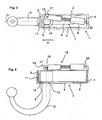
- An exemplary embodiment of the trailer coupling according to the invention consists of a trough-shaped housing 1 with side walls 2,3, a rear wall 4, a front housing wall 5 and a housing bottom 6 with a slotted guide 7.
- On the front housing wall 5 is at the level of a longitudinal axis 10 is a perpendicular to Housing bottom 6 arranged roof edge-shaped trapezoidal nose 11.
- the keyhole-shaped slotted guide 7 is arranged.
- a ball arm 12 protrudes. It is equipped in the region of the housing bottom 6 with a guide groove 13 which engages in the slide guide 7 such that a rotation of the ball arm 12 in the region of a rectangular part 8 of the slotted guide 7 prevents and allowed only in the area of a round part 9 of the slide guide 7.
- the located in the housing 1 part of the ball arm 12 is designed as a rotary axis member 14.
- the Drehachsglied 14 has a cylindrical shape, its diameter is, as well as the diameter of the ball arm 12, greater than the diameter or the inside diameter of the rectangular and round part of the cam guide 8,9 8th
- a groove 15 is arranged, in which the trapezoidal nose 11 engages in the position of use.
- a pivot axis 17 is arranged off-center, on which a bearing eye 19 of a linear drive 18 engages.
- the linear drive 18 is pivotally mounted on the rear wall 4 in a bearing 20.
- Fig. 1 shows the trailer hitch in non-use position in a plan view
- Fig. 2 in a side view.
- the linear drive 18 is fully retracted, the ball arm 12 is retracted with the guide groove 13 in the rectangular part 8 of the slide guide 7.
- the ball arm 12 is parallel to the longitudinal axis 10th
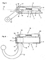
- Fig. 3 shows the hitch in an intermediate position in a plan view, Fig. 4 in a side view.
- the acting on the pivot axis 17 on the Drehachsglied 14 linear drive 18 is extended and has the ball arm 12 in the rectangular part 8 of the guide slot 7 to the round Part 9 of the guide slot 7 pushed in the direction of arrow A until the Drehachsglied 14 abuts against the trapezoidal nose 11 of the front housing wall 5, whereby the linear movement of the ball arm 12 along the longitudinal axis 10 ends.
- the guide groove 13 prevents, as long as it engages in the rectangular part 8 of the guide slot 7, a pivoting of the ball arm 12th
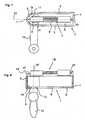
- Fig. 5 shows the trailer hitch in the pivoting movement of the ball arm 12 from the intermediate position to the position of use Fig. 7,8 in a plan view, Fig. 6 in a side view.
- the longitudinal movement of the ball arm 12 is prevented. Since the guide groove 13 on the ball arm 12 now engages in the round part 9 of the slotted guide 7, which is wider than the rectangular part 8, the ball arm 12 can now pivot about the axis of rotation 16. The pivoting is effected by the fact that the linear drive 18 does not act on the axis of rotation 16, but on the eccentric pivot axis 17. The resulting “lever” 21 causes the pivoting 12 upon further extension of the linear drive 18 of the ball arm in the direction of use position.
- Fig. 7 shows the trailer hitch in the position of use in a plan view
- Fig. 8 in a side view.
- Fig. 9 shows in a plan view of the trailer hitch after Fig. 5 in the intermediate position when pivoting in the position of use. To clarify the function of the linear drive 18 as well as the pivot axis 17 is not shown here.
- the guide groove 13 of the ball arm 12 is located in the round part 9 of the slide guide 7, the rotary axis member 14 is located on the trapezoidal nose 11 at.
- the linear actuator 18 can pivot through the eccentric articulation on the pivot axis 17, the Drehachsglied 14 and thus the ball arm 12 in the direction of arrow B until the trapezoidal nose 11 and the groove 15 face in Drehachsglied 14. Due to the further thrust of the linear drive 18, the Drehachsglied 14 and thus the ball arm 12 is still a piece along the longitudinal axis 10 moves linearly until the trapezoidal nose 11 engages the groove 15 and the Drehachsglied 14 rests flat against the front housing wall 5 Thus, the use position reached.
- Fig. 10 shows in a plan view of the device Fig. 7 in the position of use.
- the trapezoidal nose 11 has engaged in the groove 15, the Drehachsglied 14 lies flat against the front housing wall 5 at.
- Forces, which act on the ball arm (ball rod) 12 from outside, for example, by a trailer, are for the most part introduced into the housing 1; only small force components act on the linear drive 18.
Abstract
Description
Die Erfindung betrifft eine Anhängekupplung für Kraftfahrzeuge gemäß dem Oberbegriff des Anspruchs 1.The invention relates to a towing hitch for motor vehicles according to the preamble of
Eine Anhängekupplung dieser Art ist z.B. aus
Ein mit einer Kugel versehener Kupplungsarm wird mittels einer Vorrichtung zum Absenken und Schwenken aus einer von außerhalb des Kraftfahrzeuges z.B. nicht sichtbaren Ruhestellung in eine zum Befestigen eines Anhängers geeignete Betriebsstellung motorisch oder manuell angetrieben bewegt.A ball-shaped coupling arm is moved by means of a device for lowering and pivoting from outside the motor vehicle e.g. invisible resting position moves in a suitable for attaching a trailer operating position motor or manually driven.
Es sind verschiedene Ausführungsformen solcher motorisch angetriebener Anhängekupplungen bekannt, z.B. aus der
Die Bodenfreiheit reicht je nach Fahrzeugtyp gelegentlich nicht aus, besonders wenn das Fahrzeug über einer Bordsteinkante steht.The ground clearance is sometimes insufficient depending on the type of vehicle, especially when the vehicle is over a curb.
Die senkrecht angeordnete Kugelstange hat eine Bauform, die bei modernen Fahrzeugen mit besonders niedrig liegender Kofferraumkante nicht in das Fahrzeug integriert werden kann -The vertically arranged ball bar has a design that can not be integrated into the vehicle in modern vehicles with a particularly low-lying trunk edge -
Aufwendige Konstruktion - teilweise mit 2 Motoren - um die drei Bewegungsschritte Senken, Schwenken, Heben zu realisieren.Elaborate construction - partly with 2 motors - to realize the three steps of lowering, swiveling, lifting.
Aufwendige Steuerung der Bewegungsschritte entweder mechanisch oder elektrisch.Elaborate control of the movement steps either mechanically or electrically.
Passgenaue und damit teure Führungen erforderlich, die wegen der eingeleiteten Betriebskräfte teure Materialien und Bearbeitungsverfahren notwendig machen.Precisely fitting and therefore expensive guides are required, which necessitate expensive materials and processing methods due to the operating staff involved.
Es sind weitere Ausführungsformen bekannt, bei denen die Kugelstange an einem fahrzeugfesten Drehlager angeordnet sind und durch einen Motor die Kugelstange aus einer unterhalb des Fahrzeugbodens befindlichen Ruhestellung in die Betriebsstellung geschwenkt wird, wie z.B. in
Die Bodenfreiheit reicht bei bestimmten Ausführungsformen und Fahrzeugen ebenfalls nicht aus.The ground clearance is also insufficient in certain embodiments and vehicles.
Bei einigen Fahrzeugformen sind sie wegen der Art des Fahrzeugbodens nur schwer oder gar nicht zu integrieren.In some vehicle forms, they are difficult or impossible to integrate due to the nature of the vehicle floor.
Die Getriebemotoren sind hohen Belastungen ausgesetzt, wodurch sie aufwendig und teuer werden. Es sind bei bestimmten Ausführungsformen zum Festsetzen der Kugelstange zusätzliche Verriegelungsvorrichtungen erforderlich, die starkem Verschleiß unterliegen und teuer in der Herstellung sind. -The geared motors are exposed to high loads, which makes them expensive and expensive. There are additional locking devices required in certain embodiments for fixing the ball rod, which are subject to heavy wear and are expensive to manufacture. -
Die Hauptschwenklager unterliegen starken Betriebskräften und müssen daher in aufwendigen und teuren Techniken hergestellt werden.The main pivot bearings are subject to heavy operating forces and must therefore be manufactured in complex and expensive techniques.
Es sind schließlich Ausführungsformen bekannt, z.B.
Zur Realisierung der Bewegung sind unter Umständen 2 Motoren erforderlich.To realize the movement, 2 motors may be required.
Es gibt wiederum drei Bewegungsschritte - Senken - Drehen - Heben - dazu ist eine spezielle Steuerung erforderlichThere are again three movement steps - lowering - turning - lifting - this requires a special control
Die Herstellung ist wegen zweier großer, die ganz Last aufnehmenden Lager aufwendig und teuer.The production is complicated and expensive because of two large, the very load receiving bearing.
Nachdem verschiedene motorisch angetriebene Anhängekupplungen mittlerweile produziert werden, und es sich herausgestellt hat, dass alle bekannten Typen in der Herstellung für den automobilen Massenmarkt zu teuer sind, ist es die Aufgabe der Erfindung, eine motorisch angetriebene Anhängekupplung zu schaffen, die besonders einfach und billig in der Herstellung ist.After various motor-driven towbars are now produced, and it has been found that all known types are too expensive to manufacture for the mass-market automotive, it is the object of the invention to provide a motor-driven towbar, the particularly simple and inexpensive in the production is.
Zur Lösung der Aufgabe ist eine Anhängekupplung gemäß der technischen Lehre des Anspruchs 1 vorgesehen.To solve the problem, a trailer coupling according to the technical teaching of
Bei der erfindungsgemäßen Anhängekupplung kommen keine Drehlager, Verriegelungsvorrichtungen oder andere Bauteile mit hoher Fertigungsgenauigkeit zur Anwendung. Die zu bewegenden Teile werden innerhalb eines Gehäuses z.B. auf einer schiefen Ebene verschoben und ohne Verwendung eines Drehlagers z.B. über eine Kulissenführung in die Gebrauchsstellung befördert und dort durch eine Spindel nach dem Prinzip des Schraubstocks festgeklemmt. Durch den Anstellwinkel der schiefen Ebene wird die Absenkhöhe des Kugelarmes konstruktiv auf das jeweilige Fahrzeug angepasst.In the trailer coupling according to the invention no rotary bearing, locking devices or other components come with high manufacturing accuracy for use. The parts to be moved are moved within a housing, for example on an inclined plane and conveyed without the use of a pivot bearing, for example via a slotted guide in the position of use and clamped there by a spindle on the principle of vise. Due to the angle of attack of the inclined plane, the drop height of the ball arm is structurally adapted to the respective vehicle.
Ein Ausführungsbeispiel der Erfindung ist in den folgenden Abbildungen dargestellt. Aus Gründen der Übersichtlichkeit wurde auf die Darstellung des Trägers, mit dem die Anhängerkupplung am Fahrzeug befestigt wird, verzichtet. Ebenso ist die Deckplatte des Gehäuses der Anhängerkupplung nicht dargestellt, da sie den Blick auf die Funktionsbaugruppen verbirgt.An embodiment of the invention is shown in the following figures. For reasons of clarity, the representation of the carrier with which the trailer hitch is fastened to the vehicle has been dispensed with. Likewise, the cover plate of the housing of the trailer hitch is not shown because it hides the view of the functional modules.
Anhand der
Eine beispielhafte Ausführung der erfindungsgemäßen Anhängerkupplung besteht aus einem wannenförmigen Gehäuse 1 mit Seitenwänden 2,3, einer Gehäuserückwand 4, einer vorderen Gehäusewand 5 sowie einem Gehäuseboden 6 mit einer Kulissenführung 7. An der vorderen Gehäusewand 5 befindet sich in Höhe einer Längsachse 10 eine senkrecht zum Gehäuseboden 6 angeordnete dachkantförmige Trapeznase 11. Im Gehäuseboden 6 ist die schlüssellochförmige Kulissenführung 7 angeordnet.An exemplary embodiment of the trailer coupling according to the invention consists of a trough-
Durch die Kulissenführung 7 im Gehäuseboden 6 ragt ein Kugelarm 12 hindurch. Er ist im Bereich des Gehäusebodens 6 mit einer Führungsnut 13 ausgestattet, welche derart in die Kulissenführung 7 eingreift, dass eine Drehung des Kugelarmes 12 im Bereich eines rechteckigen Teiles 8 der Kulissenführung 7 verhindert und nur im Bereich eines runden Teiles 9 der Kulissenführung 7 erlaubt.Through the
Der sich im Gehäuse 1 befindliche Teil des Kugelarmes 12 ist als Drehachsglied 14 ausgeführt. Das Drehachsglied 14 besitzt eine zylindrische Form, sein Durchmesser ist, ebenso wie der Durchmesser des Kugelarmes 12, größer als der Durchmesser bzw. die lichte Weite des rechteckigen und runden Teiles 8,9 der Kulissenführung 7.The located in the
An der Seite des Drehachsgliedes 14 ist senkrecht, also parallel zu einer Drehachse 16 des Kugelarmes 12, eine Nut 15 angeordnet, in welche in der Gebrauchsstellung die Trapeznase 11 eingreift.On the side of the
An der Oberseite des Drehachsgliedes 14 ist außermittig eine Schwenkachse 17 angeordnet, an der ein Lagerauge 19 eines Linearantriebes 18 angreift. Der Linearantrieb 18 ist an der Gehäuserückwand 4 in einem Lager 20 schwenkbar gelagert.At the top of the
Der Linearantrieb 18 ist ganz eingefahren, der Kugelarm 12 ist mit der Führungsnut 13 in den rechteckigen Teil 8 der Kulissenführung 7 zurückgezogen. Der Kugelarm 12 steht parallel zur Längsachse 10.The
Der an der Schwenkachse 17 am Drehachsglied 14 angreifende Linearantrieb 18 ist ausgefahren und hat den Kugelarm 12 in dem rechteckigen Teil 8 der Kulissenführung 7 bis in den runden Teil 9 der Kulissenführung 7 in Pfeilrichtung A geschoben, bis das Drehachsglied 14 gegen die Trapeznase 11 der vorderen Gehäusewand 5 anschlägt, wodurch die lineare Bewegung des Kugelarmes 12 entlang der Längsachse 10 endet. Die Führungsnut 13 verhindert, solange sie in den rechteckigen Teil 8 der Kulissenführung 7 eingreift, ein Schwenken des Kugelarmes 12.The acting on the
Durch den Anschlag des Drehachsgliedes 14 an der Trapeznase 11 ist die Längsbewegung des Kugelarmes 12 verhindert. Da die Führungsnut 13 am Kugelarm 12 nun in den runden Teil 9 der Kulissenführung 7 eingreift, welcher breiter ist als der rechteckige Teil 8, kann der Kugelarm 12 nun um die Drehachse 16 schwenken. Das Schwenken wird dadurch bewirkt, dass der Linearantrieb 18 nicht an der Drehachse 16 angreift, sondern an der außermittigen Schwenkachse 17. Der dadurch entstehende "Hebel" 21 bewirkt, das bei weiterem Ausfahren des Linearantriebes 18 der Kugelarm 12 in Richtung Gebrauchsstellung schwenkt.By the stop of the Drehachsgliedes 14 on the
Wenn der Kugelarm 12 die in
Die Führungsnut 13 des Kugelarmes 12 befindet sich im runden Teil 9 der Kulissenführung 7, das Drehachsglied 14 liegt an der Trapeznase 11 an. Wie bereits bei
Die Trapeznase 11 hat in die Nut 15 eingegriffen, das Drehachsglied 14 liegt flächig an der vorderen Gehäusewand 5 an. Kräfte, welche von außen beispielsweise durch einen Anhänger auf den Kugelarm (Kugelstange) 12 einwirken, werden zum Grossteil in das Gehäuse 1 eingeleitet, auf den Linearantrieb 18 wirken nur kleine Kraftanteile.The
Claims (9)
- Trailer coupling for motor vehicles, in particular cars, with a coupling arm (12) carrying at one end an upright head section for the releasable fastening of a trailer and at the other end firmly connected to a hinge element (14) mounted movably in a housing (1), wherein the coupling arm (12) is adjustable to and fro by means of a manual or powered feed mechanism between a position of use aligned backwards and an inoperative position located further forward, wherein the adjusting movement is comprised of two movements in which the hinge element (14) is shifted in a first movement section from the inoperative position into a housing (1), and in a second movement section is swivelled, so that after completion of both movements, which may overlap, the coupling arm (12) assumes the position of use, characterised in that it has a manually-operated or powered linear drive (18) for swivelling the coupling arm (12), hinged so as to pivot on the hinge element (14) eccentrically to a rotation axis (16) of the hinge element (14), wherein the linear drive (18) moves the coupling arm (12), guided by a guide device for guiding the coupling arm (12) and comprising guide elements or a gate (7) mounted outside the housing (1), until the guide device releases the coupling arm (12) for swivelling, and that on completion of swivelling a recess on the hinge element (14) slides into a mating element (11) matching the recess, by which means the coupling arm (12) is fixed in the housing (1) connected to the linear drive (18) and prevented from further rotation.
- Trailer coupling according to claim 1, characterised in that the recess comprises a slot (15) or a bore or an oval recess or a trapezoidal recess, which the mating element on the housing (1) matches for the purpose of fixing the hinge element (14).
- Trailer coupling according to claim 1 or 2, characterised in that the coupling arm (12) is fixed in the housing (1) under contact pressure from the linear drive (18) and is prevented from further rotation.
- Trailer coupling according to any of the preceding claims, characterised in that the housing (1) has a continuous housing base (6) or at least two housing base sections arranged consecutively at different angles to the horizontal.
- Trailer coupling according to claim 1, characterised in that the guide elements mounted outside the housing (1) comprise baffles or rails to control the coupling arm (12).
- Trailer coupling according to any of the preceding claims, characterised in that the linear drive (18) is hinged pivotably at the hinge element (14), at a pivot axis (17) located in front of the hinge element (14), or to a hinge mounting element located within the hinge element (14), in particular a pivot axis integrated in the hinge element (14).
- Trailer coupling according to any of the preceding claims, characterised in that the housing (1) assumes an inclined position relative to the vehicle.
- Trailer coupling according to any of the preceding claims, characterised in that the coupling arm (12) is movable on one or more inclined planes of the housing (1).
- Trailer coupling according to any of the preceding claims, characterised in that the linear drive (18), through its off-centre hinging to the hinge element (14), swivels the latter until the recess (15) in the hinge element (14) and the mating element are opposite one another, and that the hinge element (14) is then moved linearly by a further thrust of the linear drive (18) along the longitudinal axis (10) until the mating element (11) engages in the recess (15) and the hinge element (14) fits up flat against the front housing wall (5).
Applications Claiming Priority (2)
| Application Number | Priority Date | Filing Date | Title |
|---|---|---|---|
| DE202004005806U | 2004-04-08 | ||
| DE202004005806U DE202004005806U1 (en) | 2004-04-08 | 2004-04-08 | trailer hitch |
Publications (2)
| Publication Number | Publication Date |
|---|---|
| EP1584500A1 EP1584500A1 (en) | 2005-10-12 |
| EP1584500B1 true EP1584500B1 (en) | 2009-02-11 |
Family
ID=32892607
Family Applications (1)
| Application Number | Title | Priority Date | Filing Date |
|---|---|---|---|
| EP05005549A Not-in-force EP1584500B1 (en) | 2004-04-08 | 2005-03-15 | Trailer coupling |
Country Status (3)
| Country | Link |
|---|---|
| EP (1) | EP1584500B1 (en) |
| AT (1) | ATE422431T1 (en) |
| DE (2) | DE202004005806U1 (en) |
Families Citing this family (6)
| Publication number | Priority date | Publication date | Assignee | Title |
|---|---|---|---|---|
| DE102004045859A1 (en) * | 2004-09-20 | 2006-03-23 | Jaeger Cartronix Gmbh | Manual drive for a trailer hitch |
| DE102006045979A1 (en) * | 2006-09-27 | 2008-04-03 | Fac Frank Abels Consulting & Technology Gesellschaft Mbh | trailer hitch |
| CN100519237C (en) * | 2007-08-28 | 2009-07-29 | 王春江 | Coupling device between traction tool and trailer like |
| DE102017118152B4 (en) | 2017-08-09 | 2020-09-24 | Fac Frank Abels Consulting & Technology Gesellschaft Mbh | Motorized swiveling trailer coupling |
| US11059336B1 (en) * | 2018-04-05 | 2021-07-13 | Charles L. Perry | Retractable hitch adaptor system |
| US20220219500A1 (en) * | 2021-01-11 | 2022-07-14 | Ford Global Technologies, Llc | Pivoting Vehicle Trailer Hitch |
Family Cites Families (14)
| Publication number | Priority date | Publication date | Assignee | Title |
|---|---|---|---|---|
| DE19654867C2 (en) | 1995-09-13 | 1998-01-22 | Cartron Fahrzeugteile Gmbh | Swiveling trailer hitch for motor vehicles |
| DE19612959A1 (en) | 1996-04-01 | 1997-10-02 | Oris Fahrzeugteile Riehle H | Trailer coupling |
| SE509538C2 (en) | 1997-06-19 | 1999-02-08 | Volvo Ab | Towbar device for motor vehicles |
| DE19826618C2 (en) | 1998-06-17 | 2001-05-03 | Peter Rocca | Towing |
| US6447000B1 (en) * | 1999-02-05 | 2002-09-10 | Popup Industries, Inc. | Mechanism for retractable gooseneck hitch ball |
| DE19944264A1 (en) | 1999-09-15 | 2001-03-22 | Jaeger Cartronix Gmbh | Trailer coupling with axial travel |
| DE10004523A1 (en) | 2000-02-02 | 2001-08-09 | Fac Frank Abels Consult & Tech | Trailer coupling for car, coupling arm of which can be retracted into bumper (fender) |
| DE10023640C2 (en) | 2000-05-13 | 2003-05-08 | Fac Frank Abels Consult & Tech | trailer hitch |
| DE10023641B4 (en) * | 2000-05-13 | 2010-04-29 | Westfalia-Automotive Gmbh | trailer hitch |
| DE10104185A1 (en) | 2001-01-23 | 2002-07-25 | Fac Frank Abels Consult & Tech | trailer hitch |
| DE10231221A1 (en) * | 2002-07-11 | 2004-01-29 | Dr.Ing.H.C. F. Porsche Ag | towbar |
| DE10243044B4 (en) * | 2002-09-12 | 2016-01-21 | Westfalia-Automotive Gmbh | trailer hitch |
| DE10243045B4 (en) | 2002-09-12 | 2016-01-21 | Westfalia-Automotive Gmbh | trailer hitch |
| DE202004006666U1 (en) * | 2003-12-13 | 2004-08-19 | Fac Frank Abels Consulting & Technology Gesellschaft Mbh | Motor vehicle trailer coupling has hitch arm with motorized retractable mounting and rotary bearing to support arm with respect to chassis |
-
2004
- 2004-04-08 DE DE202004005806U patent/DE202004005806U1/en not_active Expired - Lifetime
-
2005
- 2005-03-15 EP EP05005549A patent/EP1584500B1/en not_active Not-in-force
- 2005-03-15 DE DE502005006589T patent/DE502005006589D1/en active Active
- 2005-03-15 AT AT05005549T patent/ATE422431T1/en not_active IP Right Cessation
Also Published As
| Publication number | Publication date |
|---|---|
| EP1584500A1 (en) | 2005-10-12 |
| ATE422431T1 (en) | 2009-02-15 |
| DE202004005806U1 (en) | 2004-08-19 |
| DE502005006589D1 (en) | 2009-03-26 |
Similar Documents
| Publication | Publication Date | Title |
|---|---|---|
| EP0850147B2 (en) | Motor vehicle trailer coupling | |
| EP1584499B1 (en) | Trailer coupling | |
| DE10023640C2 (en) | trailer hitch | |
| EP1880879B1 (en) | Pivotable towing device for traction vehicles | |
| EP1435305B1 (en) | Trailer coupling | |
| EP1584500B1 (en) | Trailer coupling | |
| DE102005007430A1 (en) | Device is for releasable fixture and longitudinal positioning of seat in vehicle and involves rail, holding contour, bar contour and roll-off contour | |
| EP1637364A1 (en) | Trailer coupling | |
| EP1561610B1 (en) | Trailer hitch mechanism | |
| DE10243045B4 (en) | trailer hitch | |
| EP1586471B1 (en) | Trailer coupling | |
| EP1905617B1 (en) | Trailer tow-bar | |
| EP1541385B1 (en) | Trailer hitch | |
| EP1586470B1 (en) | Trailer coupling | |
| DE10347817B4 (en) | Towing | |
| DE10045296A1 (en) | Trailer coupling for vehicle, with ball rod having joint inside guide of coupling casing | |
| EP2657051A1 (en) | Coupling assembly for a rear carrier | |
| EP2289743A2 (en) | Hydraulic leveller | |
| DE102010043207B4 (en) | pendant | |
| DE10347816B4 (en) | Trailer coupling with load-free pivot bearing device | |
| DE202004006666U1 (en) | Motor vehicle trailer coupling has hitch arm with motorized retractable mounting and rotary bearing to support arm with respect to chassis | |
| WO2008049569A1 (en) | Trailer device | |
| EP1584498B1 (en) | Trailer coupling | |
| DE102004012483B4 (en) | Coupling device for connecting a towing vehicle with a trailer | |
| DE102007047349A1 (en) | Loading device for e.g. automatic loading of object i.e. wheelchair, into motor vehicle i.e. passenger car, has connection unit running on curve mold that is fixedly arranged at frame, where unit pivots frame based on unit position on mold |
Legal Events
| Date | Code | Title | Description |
|---|---|---|---|
| PUAI | Public reference made under article 153(3) epc to a published international application that has entered the european phase |
Free format text: ORIGINAL CODE: 0009012 |
|
| AK | Designated contracting states |
Kind code of ref document: A1 Designated state(s): AT BE BG CH CY CZ DE DK EE ES FI FR GB GR HU IE IS IT LI LT LU MC NL PL PT RO SE SI SK TR |
|
| AX | Request for extension of the european patent |
Extension state: AL BA HR LV MK YU |
|
| 17P | Request for examination filed |
Effective date: 20060317 |
|
| AKX | Designation fees paid |
Designated state(s): AT BE BG CH CY CZ DE DK EE ES FI FR GB GR HU IE IS IT LI LT LU MC NL PL PT RO SE SI SK TR |
|
| RAP1 | Party data changed (applicant data changed or rights of an application transferred) |
Owner name: WESTFALIA - AUTOMOTIVE GMBH |
|
| 17Q | First examination report despatched |
Effective date: 20070614 |
|
| GRAP | Despatch of communication of intention to grant a patent |
Free format text: ORIGINAL CODE: EPIDOSNIGR1 |
|
| GRAS | Grant fee paid |
Free format text: ORIGINAL CODE: EPIDOSNIGR3 |
|
| GRAA | (expected) grant |
Free format text: ORIGINAL CODE: 0009210 |
|
| AK | Designated contracting states |
Kind code of ref document: B1 Designated state(s): AT BE BG CH CY CZ DE DK EE ES FI FR GB GR HU IE IS IT LI LT LU MC NL PL PT RO SE SI SK TR |
|
| REG | Reference to a national code |
Ref country code: GB Ref legal event code: FG4D Free format text: NOT ENGLISH |
|
| REG | Reference to a national code |
Ref country code: CH Ref legal event code: EP |
|
| REG | Reference to a national code |
Ref country code: IE Ref legal event code: FG4D Free format text: LANGUAGE OF EP DOCUMENT: GERMAN |
|
| REF | Corresponds to: |
Ref document number: 502005006589 Country of ref document: DE Date of ref document: 20090326 Kind code of ref document: P |
|
| PG25 | Lapsed in a contracting state [announced via postgrant information from national office to epo] |
Ref country code: SI Free format text: LAPSE BECAUSE OF FAILURE TO SUBMIT A TRANSLATION OF THE DESCRIPTION OR TO PAY THE FEE WITHIN THE PRESCRIBED TIME-LIMIT Effective date: 20090211 Ref country code: NL Free format text: LAPSE BECAUSE OF FAILURE TO SUBMIT A TRANSLATION OF THE DESCRIPTION OR TO PAY THE FEE WITHIN THE PRESCRIBED TIME-LIMIT Effective date: 20090211 Ref country code: ES Free format text: LAPSE BECAUSE OF FAILURE TO SUBMIT A TRANSLATION OF THE DESCRIPTION OR TO PAY THE FEE WITHIN THE PRESCRIBED TIME-LIMIT Effective date: 20090522 Ref country code: LT Free format text: LAPSE BECAUSE OF FAILURE TO SUBMIT A TRANSLATION OF THE DESCRIPTION OR TO PAY THE FEE WITHIN THE PRESCRIBED TIME-LIMIT Effective date: 20090211 Ref country code: FI Free format text: LAPSE BECAUSE OF FAILURE TO SUBMIT A TRANSLATION OF THE DESCRIPTION OR TO PAY THE FEE WITHIN THE PRESCRIBED TIME-LIMIT Effective date: 20090211 |
|
| NLV1 | Nl: lapsed or annulled due to failure to fulfill the requirements of art. 29p and 29m of the patents act | ||
| PG25 | Lapsed in a contracting state [announced via postgrant information from national office to epo] |
Ref country code: IS Free format text: LAPSE BECAUSE OF FAILURE TO SUBMIT A TRANSLATION OF THE DESCRIPTION OR TO PAY THE FEE WITHIN THE PRESCRIBED TIME-LIMIT Effective date: 20090611 Ref country code: SE Free format text: LAPSE BECAUSE OF FAILURE TO SUBMIT A TRANSLATION OF THE DESCRIPTION OR TO PAY THE FEE WITHIN THE PRESCRIBED TIME-LIMIT Effective date: 20090511 Ref country code: PL Free format text: LAPSE BECAUSE OF FAILURE TO SUBMIT A TRANSLATION OF THE DESCRIPTION OR TO PAY THE FEE WITHIN THE PRESCRIBED TIME-LIMIT Effective date: 20090211 |
|
| REG | Reference to a national code |
Ref country code: IE Ref legal event code: FD4D |
|
| BERE | Be: lapsed |
Owner name: WESTFALIA - AUTOMOTIVE G.M.B.H. Effective date: 20090331 |
|
| PG25 | Lapsed in a contracting state [announced via postgrant information from national office to epo] |
Ref country code: DK Free format text: LAPSE BECAUSE OF FAILURE TO SUBMIT A TRANSLATION OF THE DESCRIPTION OR TO PAY THE FEE WITHIN THE PRESCRIBED TIME-LIMIT Effective date: 20090211 Ref country code: CZ Free format text: LAPSE BECAUSE OF FAILURE TO SUBMIT A TRANSLATION OF THE DESCRIPTION OR TO PAY THE FEE WITHIN THE PRESCRIBED TIME-LIMIT Effective date: 20090211 Ref country code: PT Free format text: LAPSE BECAUSE OF FAILURE TO SUBMIT A TRANSLATION OF THE DESCRIPTION OR TO PAY THE FEE WITHIN THE PRESCRIBED TIME-LIMIT Effective date: 20090713 Ref country code: IE Free format text: LAPSE BECAUSE OF FAILURE TO SUBMIT A TRANSLATION OF THE DESCRIPTION OR TO PAY THE FEE WITHIN THE PRESCRIBED TIME-LIMIT Effective date: 20090211 Ref country code: EE Free format text: LAPSE BECAUSE OF FAILURE TO SUBMIT A TRANSLATION OF THE DESCRIPTION OR TO PAY THE FEE WITHIN THE PRESCRIBED TIME-LIMIT Effective date: 20090211 Ref country code: MC Free format text: LAPSE BECAUSE OF NON-PAYMENT OF DUE FEES Effective date: 20090331 |
|
| REG | Reference to a national code |
Ref country code: CH Ref legal event code: PL |
|
| PG25 | Lapsed in a contracting state [announced via postgrant information from national office to epo] |
Ref country code: SK Free format text: LAPSE BECAUSE OF FAILURE TO SUBMIT A TRANSLATION OF THE DESCRIPTION OR TO PAY THE FEE WITHIN THE PRESCRIBED TIME-LIMIT Effective date: 20090211 Ref country code: RO Free format text: LAPSE BECAUSE OF FAILURE TO SUBMIT A TRANSLATION OF THE DESCRIPTION OR TO PAY THE FEE WITHIN THE PRESCRIBED TIME-LIMIT Effective date: 20090211 |
|
| PLBE | No opposition filed within time limit |
Free format text: ORIGINAL CODE: 0009261 |
|
| STAA | Information on the status of an ep patent application or granted ep patent |
Free format text: STATUS: NO OPPOSITION FILED WITHIN TIME LIMIT |
|
| 26N | No opposition filed |
Effective date: 20091112 |
|
| GBPC | Gb: european patent ceased through non-payment of renewal fee |
Effective date: 20090511 |
|
| PG25 | Lapsed in a contracting state [announced via postgrant information from national office to epo] |
Ref country code: LI Free format text: LAPSE BECAUSE OF NON-PAYMENT OF DUE FEES Effective date: 20090331 Ref country code: CH Free format text: LAPSE BECAUSE OF NON-PAYMENT OF DUE FEES Effective date: 20090331 Ref country code: BG Free format text: LAPSE BECAUSE OF FAILURE TO SUBMIT A TRANSLATION OF THE DESCRIPTION OR TO PAY THE FEE WITHIN THE PRESCRIBED TIME-LIMIT Effective date: 20090511 |
|
| PG25 | Lapsed in a contracting state [announced via postgrant information from national office to epo] |
Ref country code: BE Free format text: LAPSE BECAUSE OF NON-PAYMENT OF DUE FEES Effective date: 20090331 |
|
| PG25 | Lapsed in a contracting state [announced via postgrant information from national office to epo] |
Ref country code: GB Free format text: LAPSE BECAUSE OF NON-PAYMENT OF DUE FEES Effective date: 20090511 |
|
| PG25 | Lapsed in a contracting state [announced via postgrant information from national office to epo] |
Ref country code: AT Free format text: LAPSE BECAUSE OF NON-PAYMENT OF DUE FEES Effective date: 20090315 |
|
| PG25 | Lapsed in a contracting state [announced via postgrant information from national office to epo] |
Ref country code: GR Free format text: LAPSE BECAUSE OF FAILURE TO SUBMIT A TRANSLATION OF THE DESCRIPTION OR TO PAY THE FEE WITHIN THE PRESCRIBED TIME-LIMIT Effective date: 20090512 |
|
| PG25 | Lapsed in a contracting state [announced via postgrant information from national office to epo] |
Ref country code: IT Free format text: LAPSE BECAUSE OF FAILURE TO SUBMIT A TRANSLATION OF THE DESCRIPTION OR TO PAY THE FEE WITHIN THE PRESCRIBED TIME-LIMIT Effective date: 20090211 |
|
| PG25 | Lapsed in a contracting state [announced via postgrant information from national office to epo] |
Ref country code: LU Free format text: LAPSE BECAUSE OF NON-PAYMENT OF DUE FEES Effective date: 20090315 |
|
| PG25 | Lapsed in a contracting state [announced via postgrant information from national office to epo] |
Ref country code: HU Free format text: LAPSE BECAUSE OF FAILURE TO SUBMIT A TRANSLATION OF THE DESCRIPTION OR TO PAY THE FEE WITHIN THE PRESCRIBED TIME-LIMIT Effective date: 20090812 |
|
| PG25 | Lapsed in a contracting state [announced via postgrant information from national office to epo] |
Ref country code: TR Free format text: LAPSE BECAUSE OF FAILURE TO SUBMIT A TRANSLATION OF THE DESCRIPTION OR TO PAY THE FEE WITHIN THE PRESCRIBED TIME-LIMIT Effective date: 20090211 |
|
| PG25 | Lapsed in a contracting state [announced via postgrant information from national office to epo] |
Ref country code: CY Free format text: LAPSE BECAUSE OF FAILURE TO SUBMIT A TRANSLATION OF THE DESCRIPTION OR TO PAY THE FEE WITHIN THE PRESCRIBED TIME-LIMIT Effective date: 20090211 |
|
| REG | Reference to a national code |
Ref country code: DE Ref legal event code: R082 Ref document number: 502005006589 Country of ref document: DE Representative=s name: BREGENZER, MICHAEL, DIPL.-ING., DE Ref country code: DE Ref legal event code: R082 Ref document number: 502005006589 Country of ref document: DE Representative=s name: PATENTANWAELTE BREGENZER UND REULE PARTNERSCHA, DE |
|
| REG | Reference to a national code |
Ref country code: DE Ref legal event code: R082 Ref document number: 502005006589 Country of ref document: DE Representative=s name: PATENTANWAELTE BREGENZER UND REULE PARTNERSCHA, DE |
|
| REG | Reference to a national code |
Ref country code: FR Ref legal event code: PLFP Year of fee payment: 12 |
|
| REG | Reference to a national code |
Ref country code: FR Ref legal event code: PLFP Year of fee payment: 13 |
|
| REG | Reference to a national code |
Ref country code: FR Ref legal event code: PLFP Year of fee payment: 14 |
|
| PGFP | Annual fee paid to national office [announced via postgrant information from national office to epo] |
Ref country code: DE Payment date: 20220309 Year of fee payment: 18 |
|
| PGFP | Annual fee paid to national office [announced via postgrant information from national office to epo] |
Ref country code: FR Payment date: 20220203 Year of fee payment: 18 |
|
| REG | Reference to a national code |
Ref country code: DE Ref legal event code: R119 Ref document number: 502005006589 Country of ref document: DE |
|
| PG25 | Lapsed in a contracting state [announced via postgrant information from national office to epo] |
Ref country code: FR Free format text: LAPSE BECAUSE OF NON-PAYMENT OF DUE FEES Effective date: 20230331 Ref country code: DE Free format text: LAPSE BECAUSE OF NON-PAYMENT OF DUE FEES Effective date: 20231003 |