EP1586471B1 - Trailer coupling - Google Patents
Trailer coupling Download PDFInfo
- Publication number
- EP1586471B1 EP1586471B1 EP05005546A EP05005546A EP1586471B1 EP 1586471 B1 EP1586471 B1 EP 1586471B1 EP 05005546 A EP05005546 A EP 05005546A EP 05005546 A EP05005546 A EP 05005546A EP 1586471 B1 EP1586471 B1 EP 1586471B1
- Authority
- EP
- European Patent Office
- Prior art keywords
- hinge element
- housing
- trailer
- coupling arm
- coupling
- Prior art date
- Legal status (The legal status is an assumption and is not a legal conclusion. Google has not performed a legal analysis and makes no representation as to the accuracy of the status listed.)
- Not-in-force
Links
- 230000008878 coupling Effects 0.000 title claims description 27
- 238000010168 coupling process Methods 0.000 title claims description 27
- 238000005859 coupling reaction Methods 0.000 title claims description 27
- 238000004519 manufacturing process Methods 0.000 description 4
- 238000000034 method Methods 0.000 description 3
- 238000010276 construction Methods 0.000 description 1
- 230000003993 interaction Effects 0.000 description 1
- 239000000463 material Substances 0.000 description 1
- 239000002184 metal Substances 0.000 description 1
- 238000003672 processing method Methods 0.000 description 1
- 230000000284 resting effect Effects 0.000 description 1
Images


Classifications
-
- B—PERFORMING OPERATIONS; TRANSPORTING
- B60—VEHICLES IN GENERAL
- B60D—VEHICLE CONNECTIONS
- B60D1/00—Traction couplings; Hitches; Draw-gear; Towing devices
- B60D1/24—Traction couplings; Hitches; Draw-gear; Towing devices characterised by arrangements for particular functions
- B60D1/246—Traction couplings; Hitches; Draw-gear; Towing devices characterised by arrangements for particular functions for actuating the hitch by powered means
-
- B—PERFORMING OPERATIONS; TRANSPORTING
- B60—VEHICLES IN GENERAL
- B60D—VEHICLE CONNECTIONS
- B60D1/00—Traction couplings; Hitches; Draw-gear; Towing devices
- B60D1/01—Traction couplings or hitches characterised by their type
- B60D1/06—Ball-and-socket hitches, e.g. constructional details, auxiliary devices, their arrangement on the vehicle
-
- B—PERFORMING OPERATIONS; TRANSPORTING
- B60—VEHICLES IN GENERAL
- B60D—VEHICLE CONNECTIONS
- B60D1/00—Traction couplings; Hitches; Draw-gear; Towing devices
- B60D1/48—Traction couplings; Hitches; Draw-gear; Towing devices characterised by the mounting
- B60D1/54—Traction couplings; Hitches; Draw-gear; Towing devices characterised by the mounting collapsible or retractable when not in use, e.g. hide-away hitches
Landscapes
- Engineering & Computer Science (AREA)
- Transportation (AREA)
- Mechanical Engineering (AREA)
- Vehicle Cleaning, Maintenance, Repair, Refitting, And Outriggers (AREA)
- Medicines Containing Plant Substances (AREA)
- Fuel Cell (AREA)
- Agricultural Machines (AREA)
Abstract
Description
Die Erfindung betrifft eine Anhängekupplung für Kraftfahrzeuge, insbesondere für Personenkraftwagen, nach dem oberbegriff des Anspruchs 1, 2 oder 3.The invention relates to a towing hitch for motor vehicles, in particular for passenger cars, according to the preamble of
Eine solche Anhängekupplung ist z.B. aus der
Ein mit einer Kugel versehener Kupplungsarm der Anhängekupplung ist aus einer von außerhalb des Kraftfahrzeuges z.B. nicht sichtbaren Ruhestellung in eine zum Befestigen eines Anhängers geeignete Betriebsstellung motorisch oder manuell angetrieben bewegbar.A provided with a ball coupling arm of the trailer coupling is driven by a non-visible from outside the motor vehicle rest position in a suitable for attaching a trailer operating position motor or manually driven.
Es sind verschiedene Ausführungsformen solcher motorisch angetriebener Anhängekupplungen bekannt, z.B. aus der
Die Bodenfreiheit reicht (je nach Fahrzeugtyp) gelegentlich nicht aus, besonders wenn das Fahrzeug über einer Bordsteinkante steht.The ground clearance is sometimes insufficient (depending on the type of vehicle), especially when the vehicle is over a curb.
Die senkrecht angeordnete Kugelstange hat eine Bauform, die bei modernen Fahrzeugen mit besonders niedrig liegender Kofferraumkante nicht in das Fahrzeug integriert werden kann.The vertically arranged ball bar has a design that can not be integrated into the vehicle in modern vehicles with a particularly low-lying trunk edge.
Aufwendige Konstruktion - teilweise mit 2 Motoren - um die drei Bewegungsschritte Senken, Schwenken, Heben zu realisierenElaborate construction - partly with 2 motors - to realize the three steps of lowering, swiveling, lifting
Aufwendige Steuerung der Bewegungsschritte entweder mechanisch oder elektrisch sowie passgenaue und damit teure Führungen sind erforderlich, die wegen der eingeleiteten Betriebskräfte teure Materialien und Bearbeitungsverfahren notwendig machen.Elaborate control of the movement steps either mechanically or electrically as well as accurately fitting and therefore expensive guides are required, which necessitate expensive materials and processing methods due to the operating forces introduced.
Es sind weitere Ausführungsformen bekannt, bei denen die Kugelstange an einem fahrzeugfesten Drehlager angeordnet sind und durch einen Motor die Kugelstange aus einer unterhalb des Fahrzeugbodens befindlichen Ruhestellung in die Betriebsstellung geschwenkt wird, wie z.B. in
Die Bodenfreiheit reicht bei bestimmten Ausführungsformen und Fahrzeugen ebenfalls nicht aus.The ground clearance is also insufficient in certain embodiments and vehicles.
Bei einigen Fahrzeugformen sind sie wegen der Art des Fahrzeugbodens nur schwer oder gar nicht zu integrieren.In some vehicle forms, they are difficult or impossible to integrate due to the nature of the vehicle floor.
Die Getriebemotoren sind hohen Belastungen ausgesetzt, wodurch sie aufwendig und teuer werden. Es sind bei bestimmten Ausführungsformen zum Festsetzen der Kugelstange zusätzliche Verriegelungsvorrichtungen erforderlich, die starkem verschleiß unterliegen und teuer in der Herstellung sind.The geared motors are exposed to high loads, which makes them expensive and expensive. There are additional locking devices required in certain embodiments for fixing the ball rod, which are subject to heavy wear and are expensive to manufacture.
Die Hauptschwenklager unterliegen starken Betriebskräften und müssen daher in aufwendigen und teuren Techniken hergestellt werden.The main pivot bearings are subject to heavy operating forces and must therefore be manufactured in complex and expensive techniques.
Es sind schließlich Ausführungsformen bekannt, z.B.
Zur Realisierung der Bewegung sind unter Umstanden 2 Motoren erforderlichTo realize the movement, two motors may be required
Es gibt wiederum drei Bewegungsschritte - Senken - Drehen - Heben - dazu ist eine spezielle Steuerung erforderlich.There are again three movement steps - lowering - turning - lifting - this requires a special control.
Die Herstellung ist wegen zweier großer, die ganz Last aufnehmenden Lager aufwendig und teuer.The production is complicated and expensive because of two large, the very load receiving bearing.
Nachdem verschiedene motorisch angetriebene Anhängekupplungen mittlerweile produziert werden, und es sich herausgestellt hat, dass alle bekannten Typen in der Herstellung für den automobilen Massenmarkt zu teuer sind, ist es die Aufgabe der Erfindung, eine motorisch angetriebene Anhängekupplung zu schaffen, die besonders einfach und billig in der Herstellung ist.After various motor-driven towbars are now produced, and it has been found that all known types are too expensive to manufacture for the mass-market automotive, it is the object of the invention to provide a motor-driven towbar, the particularly simple and inexpensive in the production is.
Zur Lösung der Aufgabe ist eine Anhängekupplung gemäß der technischen Lehre des Anspruchs 1 2 oder 3 vorgesehen.To solve the problem, a trailer coupling according to the technical teaching of
Ein Ausführungsbeispiel der Erfindung ist in den folgenden Abbildungen dargestellt. Aus Gründen der Übersichtlichkeit wurde auf die Darstellung des Trägers, mit dem die Anhängerkupplung am Fahrzeug befestigt wird, verzichtet. Ebenso ist die Deckplatte des Gehäuses der Anhängerkupplung nicht dargestellt, da sie den Blick auf die Funktionsbaugruppen verbirgt.An embodiment of the invention is shown in the following figures. For reasons of clarity, the representation of the carrier with which the trailer hitch is fastened to the vehicle has been dispensed with. Likewise, the cover plate of the housing of the trailer hitch is not shown because it hides the view of the functional modules.
Anhand der Figuren 1 bis 13 wird die Funktion der Erfindung erläutert.The function of the invention will be explained with reference to FIGS. 1 to 13.
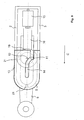
Eine beispielhafte Ausführung der erfindungsgemäßen Anhängerkupplung besteht aus einem wannenförmigen Gehäuse 1 mit Seitenwänden 2, 3, einer Gehäuserückwand 4, einer vorderen Gehäusewand 5 sowie einem Gehäuseboden 6 mit einem Schlitz 7.An exemplary embodiment of the trailer coupling according to the invention consists of a trough-
Durch den Schlitz 7 im Gehäuseboden 6 ragt ein Kugelarm 9 hindurch. Der sich im Gehäuse 1 befindliche Teil des Kugelarmes 9 ist als Drehachsglied 10 ausgeführt. Das Drehachsglied 10 besitzt im unteren und oberen Teil eine zylindrische Form, dessen Durchmesser größer als die lichte Weite des Schlitzes 7. Der obere Teil des Drehachsgliedes 10 besitzt eine Trapeznut und wird in Fig. 5 näher beschrieben. Zwischen dem oberen und unteren Teil des Drehachsgliedes 10 ist eine Ringnut 18 angeordnet, in die eine Anlenkung 16 eines Linearantriebes 15 eingreift. Der Linearantrieb 15 ist an der Gehäuserückwand 4 in einem Lager 24 schwenkbar gelagert.Through the
Fig. 1 zeigt die Anhängerkupplung in Nichtgebrauchsstellung in einer Draufsicht, Fig. 2 in einer Seitenansicht.Fig. 1 shows the trailer hitch in non-use position in a plan view, Fig. 2 in a side view.
Der Linearantrieb 15 ist ganz eingefahren, der Kugelarm 9 ist im Schlitz 7 in Richtung Gehäuserückwand 4 zurückgezogen. Der Kugelarm 9 steht parallel zur Längsachse 8.The
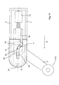
Fig. 3 zeigt die Anhängekupplung in der Gebrauchsstellung in einer Draufsicht. Fig. 4 in einer Seitenansicht. Die Kulisse 14 ist hier nicht dargestellt, um die Lage des Drehachsgliedes in der Gebrauchsstellung zu zeigen.Fig. 3 shows the hitch in the position of use in a plan view. Fig. 4 in a side view. The
Der an einer Ringnut 18 am Drehachsglied 10 angreifende Linearantrieb 15 ist ausgefahren und hat den Kugelarm 9 gegen die vordere Gehäusewand 5 geschoben. Eine Trapeznase 21 greift in eine Trapeznut 20 ein. Während der Bewegung hat der Kugelarm 9 durch das Zusammenwirken von Stift 11 und Kulisse 14 eine Schwenkbewegung um die Schwenkachse 12 durchgeführt, welche in den Fig 8 bis 13 näher erläutert wird.The acting on an
In der Gebrauchsstellung ist der Kugelarm 9 durch das Eingreifen der Trapeznase 21 an der Gehäuserückwand 5 in die Trapeznut 20 des Drehachsgliedes 10 sowie durch das Anliegen des unteren und oberen Teils 17, 19 des Drehachsgliedes 10 an der hinteren 2 und der vorderen Seitenwand 3 festgesetzt. Dadurch werden der Grossteil der Kräfte, die von außen z.B. durch einen Anhänger auf den Kugelarm 9 einwirken, in das Gehäuse 1 eingeleitet. Nur ein kleiner Teil dieser Kräfte wirken auf den Linearantrieb 15.In the position of use of the
Fig. 5 zeigt den Kugelarm 9 mit dem Drehachsglied 10 in einer Draufsicht, Fig. 6 in einer Seitenansicht.Fig. 5 shows the
Das Drehachsglied 10 besteht aus einem unteren zylindrischen Teil 17 und einem oberen zylindrischen Teil 19. Im oberen Teil 19 ist eine Trapeznut 20 eingearbeitet. Zwischen dem unteren und oberen Teil 17, 19 ist eine Ringnut 18 angeordnet, an der der Linearantrieb 15 mit der Anlenkung 16 angreift.The Drehachsglied 10 consists of a lower
Fig. 7 zeigt die Verbindung zwischen Kugelarm 9 und Linearantrieb 15 in einer Explosionsdarstellung.Fig. 7 shows the connection between the
An der Anlenkung 16, die z.B. Teil einer Gewindehülse eines Spindelantriebes sein kann, befindet sich auf der dem Drehachsglied 10 zugewandten Seite eine teilkreisförmige Lagerfläche 22, deren Radius dem Radius der Ringnut 18 entspricht. Eine U-förmige Lagerfläche 23, die z.B. als U-förmiger Blechstreifen ausgeführt sein kann, umfasst den Kugelarm 9 in der Ringnut 18 und bildet bei Zusammenführung beider Teile in Pfeilrichtungen A, B mit der Lagerfläche 22 ein kreisförmiges Lager, in dem sich der Kugelarm 9 um die Schwenkachse 12 drehen kann. Die Verbindung zwischen den Lagerteilen 22, 23 ist hier nicht näher dargestellt, sie kann z.B. durch eine Schraub- oder Nietverbindung realisiert sein.At the
Die Fig 8 bis 13 zeigen den Ablauf eines Ausschwenkvorganges, der Einschwenkvorgang läuft sinngemäß in umgekehrter Reihenfolge ab.8 to 13 show the sequence of a Ausschwenkvorganges, the Einschwenkvorgang runs mutatis mutandis in the reverse order.
In Fig. 8 befindet sich der Kugelarm 9 in der Nichtgebrauchsstellung. Der Stift 11 hat noch nicht in den Kulissenschlitz 14 eingegriffen. Unterer und oberer zylindrischer Teil 17, 19 des Drehachsgliedes 10 liegen an der hinteren und vorderen Gehäusewand 2, 3 an.In Fig. 8, the
In Fig. 9 hat der Linearantrieb 15 die Anlenkung 16 und damit den Kugelarm 9 in Pfeilrichtung C bewegt. Der Stift 11 greift in den Kulissenschlitz 14 ein. An dieser Stelle endet die rein lineare Bewegung des Kugelarmes 9.In FIG. 9, the
In Fig. 10 ist der Schwenkvorgang eingeleitet. Der Stift 11 folgt der Krümmung des Kulissenschlitzes 14, dadurch wird das Drehachsglied 10 und damit der Kugelarm 9 um die Schwenkachse 12 in Pfeilrichtung D geschwenkt. Die Bewegungen des Drehachsgliedes 10 sind in Längsrichtung des Gehäuses 1 durch den Linearantrieb 15 und rechtwinklig dazu durch den an der Wand des Kulissenschlitzes 14 anliegenden Stift 11 sowie durch die an der hinteren Seitenwand 2 anliegenden zylindrischer Teile 17, 19 begrenzt.In Fig. 10, the pivoting process is initiated. The
In Fig. 11 und 12 ist der weitere Ablauf des Schwenkvorganges dargestellt.In Fig. 11 and 12, the further course of the pivoting process is shown.
In Fig. 13 ist der Schwenkvorgang abgeschlossen, der Kugelarm 9 ist in der Gebrauchsstellung. Der Kugelarm 9 ist durch das Eingreifen der Trapeznase 21 an der Gehäuserückwand 5 in die Trapeznut 20 des Drehachsgliedes 10 sowie durch das Anliegen des unteren und oberen Teils 17, 19 des Drehachsgliedes 10 an der hinteren 2 und der vorderen Seitenwand 3 festgesetzt. Dadurch werden der Großteil der Kräfte, die von außen z.B. durch einen Anhänger auf den Kugelarm 9 einwirken, in das Gehäuse 1 eingeleitet. Nur ein kleiner Teil dieser Kräfte wirken auf den Linearantrieb 15.In Fig. 13, the pivoting operation is completed, the
Solange der Linearantrieb 15 sich nicht wieder in die entgegengesetzte Richtung bewegt, bleibt der Kugelarm 9 fest in der Gebrauchsstellung, von außen einwirkende Kräfte werden in das Gehäuse und entlang der Längsachse 8 in den Linearantrieb 15 eingeleitet.As long as the
Claims (9)
- Trailer coupling for motor vehicles, in particular motor cars, with a coupling arm (9) carrying at one end an upright head section for the releasable fastening of a trailer and firmly connected at the other end by a hinge element (10) mounted movably in a housing (1), wherein the coupling arm (9) is adjustable to and fro by means of a feed mechanism between a position of use facing towards the rear, and an inoperative position in which it is positioned further forward, wherein the adjustment movement by means of the manually or power-operated feed mechanism is comprised of two movements, characterised in that the hinge element (10), starting from the inoperative position, is shifted in a first movement section into a housing (1), and in a second movement section is swivelled so that the coupling arm (9), after completion of both movements, which may overlap, adopts the position of use, and that there is eccentrically mounted on the upper end of the hinge element (10) a driving pin (11) which runs inside a gate (4) on the housing (1) and sets the hinge element (10) into rotation around its centre axis (12), and that the hinge element (10) swivels until a recess (20) in the hinge element (10) engages with and is wedged by a matching formed part (21) on the housing (1), so that the hinge element (10) is held unable to rotate.
- Trailer coupling for motor vehicles, in particular motor cars, with a coupling arm (9) carrying at one end an upright head section for the releasable fastening of a trailer and firmly connected at the other end by a hinge element (10) mounted movably in a housing (1), wherein the coupling arm (9) is adjustable to and fro by means of a feed mechanism between a position of use facing towards the rear, and an inoperative position in which it is positioned further forward, wherein the trailer coupling has guide elements fitted outside the housing (1) for swivelling the coupling arm and the adjustment movement by means of the manually or power-operated feed mechanism is comprised of two movements, characterised in that the hinge element (10), starting from the inoperative position, is shifted in a first movement section into a housing (1), and in a second movement section is swivelled so that the coupling arm (9), after completion of both movements, which may overlap, adopts the position of use, and that the coupling arm swivels until a recess (20) in the hinge element (10) engages with and is wedged by a matching formed part (21) on the housing (1), so that the hinge element (10) is held unable to rotate.
- Trailer coupling for motor vehicles, in particular motor cars, with a coupling arm (9) carrying at one end an upright head section for the releasable fastening of a trailer and firmly connected at the other end by a hinge element (10) mounted movably in a housing (1), wherein the coupling arm (9) is adjustable to and fro by means of a feed mechanism between a position of use facing towards the rear, and an inoperative position in which it is positioned further forward, and the adjustment movement by means of the manually or power-operated feed mechanism is comprised of two movements, characterised in that the hinge element (10), starting from the inoperative position, is shifted in a first movement section into a housing (1), and in a second movement section is swivelled so that the coupling arm (9), after completion of both movements, which may overlap, adopts the position of use, and that the hinge element (10) is in the form of a gear and at the end of its linear movement strikes against a rack mounted in the housing, in which the gear-like hinge element engages and the hinge element (10) swivels, and that the hinge element (10) swivels until a recess (20) in the hinge element (10) engages with and is wedged by a matching formed part (21) on the housing (1), so that the hinge element (10) is held unable to rotate.
- Trailer coupling according to claim 1, 2 or 3, characterised in that the recess (20) and the formed part (21) are trapezoidal.
- Trailer coupling according to claim 1, 2 or 3, characterised in that the housing (1) has a continuous housing base (6) or at least two housing base sections arranged consecutively at different angles to the horizontal.
- Trailer coupling according to claim 1, 2 or 3, characterised in that the hinge element (10) is swivelled through ca. 90 degrees until the recess (20) in the hinge element (10) engages in the formed part (21) on the housing (1).
- Trailer coupling according to claim 1, 2 or 3, characterised in that the hinge element (10) is held non-rotatably in its position of use by the contact pressure of the actuator (15).
- Trailer coupling according to claim 1, 2 or 3, characterised in that the hinge element (10) is fixed in the position of use at a rear (2) and a front side wall (3) of the housing (1).
- Trailer coupling according to claim 2, characterised in that the guide elements located outside the housing (1) are in the form of baffles or rails.
Applications Claiming Priority (2)
| Application Number | Priority Date | Filing Date | Title |
|---|---|---|---|
| DE202004006204U | 2004-04-17 | ||
| DE202004006204U DE202004006204U1 (en) | 2004-04-17 | 2004-04-17 | trailer hitch |
Publications (2)
| Publication Number | Publication Date |
|---|---|
| EP1586471A1 EP1586471A1 (en) | 2005-10-19 |
| EP1586471B1 true EP1586471B1 (en) | 2008-01-30 |
Family
ID=32668344
Family Applications (1)
| Application Number | Title | Priority Date | Filing Date |
|---|---|---|---|
| EP05005546A Not-in-force EP1586471B1 (en) | 2004-04-17 | 2005-03-15 | Trailer coupling |
Country Status (3)
| Country | Link |
|---|---|
| EP (1) | EP1586471B1 (en) |
| AT (1) | ATE385219T1 (en) |
| DE (2) | DE202004006204U1 (en) |
Families Citing this family (6)
| Publication number | Priority date | Publication date | Assignee | Title |
|---|---|---|---|---|
| DE102006051096B4 (en) * | 2006-10-25 | 2013-09-12 | Mvg Metallverarbeitungsgesellschaft Mbh | hitch |
| DE102008043318A1 (en) | 2008-10-30 | 2010-05-12 | Mvg Metallverarbeitungsgesellschaft Mbh | Towing |
| DE102017118152B4 (en) | 2017-08-09 | 2020-09-24 | Fac Frank Abels Consulting & Technology Gesellschaft Mbh | Motorized swiveling trailer coupling |
| US11059336B1 (en) * | 2018-04-05 | 2021-07-13 | Charles L. Perry | Retractable hitch adaptor system |
| SE544412C2 (en) * | 2019-03-12 | 2022-05-10 | Brink Towing Systems B V | Retractable towing hook arrangement |
| US20220219500A1 (en) * | 2021-01-11 | 2022-07-14 | Ford Global Technologies, Llc | Pivoting Vehicle Trailer Hitch |
Family Cites Families (15)
| Publication number | Priority date | Publication date | Assignee | Title |
|---|---|---|---|---|
| DE3328524A1 (en) * | 1983-08-06 | 1985-02-21 | Daimler-Benz Ag, 7000 Stuttgart | Trailer coupling for vehicles |
| DE19654867C2 (en) | 1995-09-13 | 1998-01-22 | Cartron Fahrzeugteile Gmbh | Swiveling trailer hitch for motor vehicles |
| DE19612959A1 (en) | 1996-04-01 | 1997-10-02 | Oris Fahrzeugteile Riehle H | Trailer coupling |
| SE509538C2 (en) | 1997-06-19 | 1999-02-08 | Volvo Ab | Towbar device for motor vehicles |
| DE19826618C2 (en) | 1998-06-17 | 2001-05-03 | Peter Rocca | Towing |
| US6447000B1 (en) * | 1999-02-05 | 2002-09-10 | Popup Industries, Inc. | Mechanism for retractable gooseneck hitch ball |
| DE19944264A1 (en) | 1999-09-15 | 2001-03-22 | Jaeger Cartronix Gmbh | Trailer coupling with axial travel |
| DE10004523A1 (en) | 2000-02-02 | 2001-08-09 | Fac Frank Abels Consult & Tech | Trailer coupling for car, coupling arm of which can be retracted into bumper (fender) |
| DE10023640C2 (en) | 2000-05-13 | 2003-05-08 | Fac Frank Abels Consult & Tech | trailer hitch |
| DE10023641B4 (en) * | 2000-05-13 | 2010-04-29 | Westfalia-Automotive Gmbh | trailer hitch |
| DE10104185A1 (en) | 2001-01-23 | 2002-07-25 | Fac Frank Abels Consult & Tech | trailer hitch |
| DE10231221A1 (en) * | 2002-07-11 | 2004-01-29 | Dr.Ing.H.C. F. Porsche Ag | towbar |
| DE10243044B4 (en) * | 2002-09-12 | 2016-01-21 | Westfalia-Automotive Gmbh | trailer hitch |
| DE10243045B4 (en) * | 2002-09-12 | 2016-01-21 | Westfalia-Automotive Gmbh | trailer hitch |
| DE202004006666U1 (en) * | 2003-12-13 | 2004-08-19 | Fac Frank Abels Consulting & Technology Gesellschaft Mbh | Motor vehicle trailer coupling has hitch arm with motorized retractable mounting and rotary bearing to support arm with respect to chassis |
-
2004
- 2004-04-17 DE DE202004006204U patent/DE202004006204U1/en not_active Expired - Lifetime
-
2005
- 2005-03-15 DE DE502005002708T patent/DE502005002708D1/en active Active
- 2005-03-15 AT AT05005546T patent/ATE385219T1/en not_active IP Right Cessation
- 2005-03-15 EP EP05005546A patent/EP1586471B1/en not_active Not-in-force
Also Published As
| Publication number | Publication date |
|---|---|
| EP1586471A1 (en) | 2005-10-19 |
| ATE385219T1 (en) | 2008-02-15 |
| DE202004006204U1 (en) | 2004-07-01 |
| DE502005002708D1 (en) | 2008-03-20 |
Similar Documents
| Publication | Publication Date | Title |
|---|---|---|
| EP1375219B1 (en) | Roller blind for rear window with liftable storage box | |
| EP0850147B2 (en) | Motor vehicle trailer coupling | |
| DE10023640C2 (en) | trailer hitch | |
| EP1584499B1 (en) | Trailer coupling | |
| EP1637364B1 (en) | Trailer coupling | |
| EP1880879B1 (en) | Pivotable towing device for traction vehicles | |
| DE102005007430A1 (en) | Device is for releasable fixture and longitudinal positioning of seat in vehicle and involves rail, holding contour, bar contour and roll-off contour | |
| EP1586471B1 (en) | Trailer coupling | |
| EP1894752A1 (en) | Trailer coupling with extensible and retractable tow hook | |
| WO2014001013A1 (en) | Adjustment device for adjusting the position of a windscreen | |
| EP1584500B1 (en) | Trailer coupling | |
| DE10243044B4 (en) | trailer hitch | |
| EP1586470B1 (en) | Trailer coupling | |
| EP1541385B1 (en) | Trailer hitch | |
| EP2289743B1 (en) | Hydraulic leveller | |
| WO2011009537A1 (en) | Vehicle with swing-out mast arm assembly | |
| DE10347817B4 (en) | Towing | |
| EP1488943B1 (en) | Motorised trailer hitch | |
| DE3003175A1 (en) | Rake adjustment for car seat - has spindle drive with servo driven coaxial worm gear | |
| DE202004006666U1 (en) | Motor vehicle trailer coupling has hitch arm with motorized retractable mounting and rotary bearing to support arm with respect to chassis | |
| DE10347816B4 (en) | Trailer coupling with load-free pivot bearing device | |
| EP1708910B1 (en) | Windshield wiper system for vehicles, particularly road vehicles | |
| EP1584498B1 (en) | Trailer coupling | |
| EP1701870B1 (en) | Wiper system for wiping a windscreen | |
| DE10146382A1 (en) | Lifting bed has recliner surface movable by lifting mechanism, two main scissors arms intersecting on swivel bearing, lever, pivot bearing and fixtures on vehicle |
Legal Events
| Date | Code | Title | Description |
|---|---|---|---|
| PUAI | Public reference made under article 153(3) epc to a published international application that has entered the european phase |
Free format text: ORIGINAL CODE: 0009012 |
|
| AK | Designated contracting states |
Kind code of ref document: A1 Designated state(s): AT BE BG CH CY CZ DE DK EE ES FI FR GB GR HU IE IS IT LI LT LU MC NL PL PT RO SE SI SK TR |
|
| AX | Request for extension of the european patent |
Extension state: AL BA HR LV MK YU |
|
| 17P | Request for examination filed |
Effective date: 20060323 |
|
| AKX | Designation fees paid |
Designated state(s): AT BE BG CH CY CZ DE DK EE ES FI FR GB GR HU IE IS IT LI LT LU MC NL PL PT RO SE SI SK TR |
|
| RAP1 | Party data changed (applicant data changed or rights of an application transferred) |
Owner name: WESTFALIA - AUTOMOTIVE GMBH |
|
| 17Q | First examination report despatched |
Effective date: 20070209 |
|
| GRAP | Despatch of communication of intention to grant a patent |
Free format text: ORIGINAL CODE: EPIDOSNIGR1 |
|
| GRAS | Grant fee paid |
Free format text: ORIGINAL CODE: EPIDOSNIGR3 |
|
| GRAA | (expected) grant |
Free format text: ORIGINAL CODE: 0009210 |
|
| AK | Designated contracting states |
Kind code of ref document: B1 Designated state(s): AT BE BG CH CY CZ DE DK EE ES FI FR GB GR HU IE IS IT LI LT LU MC NL PL PT RO SE SI SK TR |
|
| REG | Reference to a national code |
Ref country code: GB Ref legal event code: FG4D Free format text: NOT ENGLISH |
|
| REG | Reference to a national code |
Ref country code: CH Ref legal event code: EP |
|
| REG | Reference to a national code |
Ref country code: IE Ref legal event code: FG4D Free format text: LANGUAGE OF EP DOCUMENT: GERMAN |
|
| REF | Corresponds to: |
Ref document number: 502005002708 Country of ref document: DE Date of ref document: 20080320 Kind code of ref document: P |
|
| PG25 | Lapsed in a contracting state [announced via postgrant information from national office to epo] |
Ref country code: FI Free format text: LAPSE BECAUSE OF FAILURE TO SUBMIT A TRANSLATION OF THE DESCRIPTION OR TO PAY THE FEE WITHIN THE PRESCRIBED TIME-LIMIT Effective date: 20080130 Ref country code: ES Free format text: LAPSE BECAUSE OF FAILURE TO SUBMIT A TRANSLATION OF THE DESCRIPTION OR TO PAY THE FEE WITHIN THE PRESCRIBED TIME-LIMIT Effective date: 20080511 Ref country code: IS Free format text: LAPSE BECAUSE OF FAILURE TO SUBMIT A TRANSLATION OF THE DESCRIPTION OR TO PAY THE FEE WITHIN THE PRESCRIBED TIME-LIMIT Effective date: 20080530 |
|
| NLV1 | Nl: lapsed or annulled due to failure to fulfill the requirements of art. 29p and 29m of the patents act | ||
| GBV | Gb: ep patent (uk) treated as always having been void in accordance with gb section 77(7)/1977 [no translation filed] | ||
| BERE | Be: lapsed |
Owner name: WESTFALIA - AUTOMOTIVE G.M.B.H. Effective date: 20080331 |
|
| PG25 | Lapsed in a contracting state [announced via postgrant information from national office to epo] |
Ref country code: PL Free format text: LAPSE BECAUSE OF FAILURE TO SUBMIT A TRANSLATION OF THE DESCRIPTION OR TO PAY THE FEE WITHIN THE PRESCRIBED TIME-LIMIT Effective date: 20080130 Ref country code: PT Free format text: LAPSE BECAUSE OF FAILURE TO SUBMIT A TRANSLATION OF THE DESCRIPTION OR TO PAY THE FEE WITHIN THE PRESCRIBED TIME-LIMIT Effective date: 20080630 Ref country code: SI Free format text: LAPSE BECAUSE OF FAILURE TO SUBMIT A TRANSLATION OF THE DESCRIPTION OR TO PAY THE FEE WITHIN THE PRESCRIBED TIME-LIMIT Effective date: 20080130 |
|
| REG | Reference to a national code |
Ref country code: IE Ref legal event code: FD4D |
|
| PG25 | Lapsed in a contracting state [announced via postgrant information from national office to epo] |
Ref country code: SE Free format text: LAPSE BECAUSE OF FAILURE TO SUBMIT A TRANSLATION OF THE DESCRIPTION OR TO PAY THE FEE WITHIN THE PRESCRIBED TIME-LIMIT Effective date: 20080430 Ref country code: CZ Free format text: LAPSE BECAUSE OF FAILURE TO SUBMIT A TRANSLATION OF THE DESCRIPTION OR TO PAY THE FEE WITHIN THE PRESCRIBED TIME-LIMIT Effective date: 20080130 Ref country code: NL Free format text: LAPSE BECAUSE OF FAILURE TO SUBMIT A TRANSLATION OF THE DESCRIPTION OR TO PAY THE FEE WITHIN THE PRESCRIBED TIME-LIMIT Effective date: 20080130 Ref country code: SK Free format text: LAPSE BECAUSE OF FAILURE TO SUBMIT A TRANSLATION OF THE DESCRIPTION OR TO PAY THE FEE WITHIN THE PRESCRIBED TIME-LIMIT Effective date: 20080130 Ref country code: DK Free format text: LAPSE BECAUSE OF FAILURE TO SUBMIT A TRANSLATION OF THE DESCRIPTION OR TO PAY THE FEE WITHIN THE PRESCRIBED TIME-LIMIT Effective date: 20080130 Ref country code: IE Free format text: LAPSE BECAUSE OF FAILURE TO SUBMIT A TRANSLATION OF THE DESCRIPTION OR TO PAY THE FEE WITHIN THE PRESCRIBED TIME-LIMIT Effective date: 20080130 Ref country code: MC Free format text: LAPSE BECAUSE OF NON-PAYMENT OF DUE FEES Effective date: 20080331 |
|
| EN | Fr: translation not filed | ||
| PG25 | Lapsed in a contracting state [announced via postgrant information from national office to epo] |
Ref country code: RO Free format text: LAPSE BECAUSE OF FAILURE TO SUBMIT A TRANSLATION OF THE DESCRIPTION OR TO PAY THE FEE WITHIN THE PRESCRIBED TIME-LIMIT Effective date: 20080130 |
|
| PLBE | No opposition filed within time limit |
Free format text: ORIGINAL CODE: 0009261 |
|
| STAA | Information on the status of an ep patent application or granted ep patent |
Free format text: STATUS: NO OPPOSITION FILED WITHIN TIME LIMIT |
|
| PG25 | Lapsed in a contracting state [announced via postgrant information from national office to epo] |
Ref country code: GB Free format text: LAPSE BECAUSE OF FAILURE TO SUBMIT A TRANSLATION OF THE DESCRIPTION OR TO PAY THE FEE WITHIN THE PRESCRIBED TIME-LIMIT Effective date: 20080130 |
|
| 26N | No opposition filed |
Effective date: 20081031 |
|
| PG25 | Lapsed in a contracting state [announced via postgrant information from national office to epo] |
Ref country code: EE Free format text: LAPSE BECAUSE OF FAILURE TO SUBMIT A TRANSLATION OF THE DESCRIPTION OR TO PAY THE FEE WITHIN THE PRESCRIBED TIME-LIMIT Effective date: 20080130 Ref country code: LT Free format text: LAPSE BECAUSE OF FAILURE TO SUBMIT A TRANSLATION OF THE DESCRIPTION OR TO PAY THE FEE WITHIN THE PRESCRIBED TIME-LIMIT Effective date: 20080130 |
|
| PG25 | Lapsed in a contracting state [announced via postgrant information from national office to epo] |
Ref country code: BE Free format text: LAPSE BECAUSE OF NON-PAYMENT OF DUE FEES Effective date: 20080331 |
|
| PG25 | Lapsed in a contracting state [announced via postgrant information from national office to epo] |
Ref country code: FR Free format text: LAPSE BECAUSE OF FAILURE TO SUBMIT A TRANSLATION OF THE DESCRIPTION OR TO PAY THE FEE WITHIN THE PRESCRIBED TIME-LIMIT Effective date: 20081121 Ref country code: BG Free format text: LAPSE BECAUSE OF FAILURE TO SUBMIT A TRANSLATION OF THE DESCRIPTION OR TO PAY THE FEE WITHIN THE PRESCRIBED TIME-LIMIT Effective date: 20080430 |
|
| PG25 | Lapsed in a contracting state [announced via postgrant information from national office to epo] |
Ref country code: CY Free format text: LAPSE BECAUSE OF FAILURE TO SUBMIT A TRANSLATION OF THE DESCRIPTION OR TO PAY THE FEE WITHIN THE PRESCRIBED TIME-LIMIT Effective date: 20080130 |
|
| PG25 | Lapsed in a contracting state [announced via postgrant information from national office to epo] |
Ref country code: IT Free format text: LAPSE BECAUSE OF FAILURE TO SUBMIT A TRANSLATION OF THE DESCRIPTION OR TO PAY THE FEE WITHIN THE PRESCRIBED TIME-LIMIT Effective date: 20080130 Ref country code: AT Free format text: LAPSE BECAUSE OF NON-PAYMENT OF DUE FEES Effective date: 20080315 |
|
| REG | Reference to a national code |
Ref country code: CH Ref legal event code: PL |
|
| PG25 | Lapsed in a contracting state [announced via postgrant information from national office to epo] |
Ref country code: LI Free format text: LAPSE BECAUSE OF NON-PAYMENT OF DUE FEES Effective date: 20090331 Ref country code: CH Free format text: LAPSE BECAUSE OF NON-PAYMENT OF DUE FEES Effective date: 20090331 |
|
| PG25 | Lapsed in a contracting state [announced via postgrant information from national office to epo] |
Ref country code: LU Free format text: LAPSE BECAUSE OF NON-PAYMENT OF DUE FEES Effective date: 20080315 Ref country code: HU Free format text: LAPSE BECAUSE OF FAILURE TO SUBMIT A TRANSLATION OF THE DESCRIPTION OR TO PAY THE FEE WITHIN THE PRESCRIBED TIME-LIMIT Effective date: 20080731 |
|
| PG25 | Lapsed in a contracting state [announced via postgrant information from national office to epo] |
Ref country code: TR Free format text: LAPSE BECAUSE OF FAILURE TO SUBMIT A TRANSLATION OF THE DESCRIPTION OR TO PAY THE FEE WITHIN THE PRESCRIBED TIME-LIMIT Effective date: 20080130 |
|
| PG25 | Lapsed in a contracting state [announced via postgrant information from national office to epo] |
Ref country code: GR Free format text: LAPSE BECAUSE OF FAILURE TO SUBMIT A TRANSLATION OF THE DESCRIPTION OR TO PAY THE FEE WITHIN THE PRESCRIBED TIME-LIMIT Effective date: 20080501 |
|
| REG | Reference to a national code |
Ref country code: DE Ref legal event code: R082 Ref document number: 502005002708 Country of ref document: DE Representative=s name: BREGENZER, MICHAEL, DIPL.-ING., DE Ref country code: DE Ref legal event code: R082 Ref document number: 502005002708 Country of ref document: DE Representative=s name: PATENTANWAELTE BREGENZER UND REULE PARTNERSCHA, DE |
|
| REG | Reference to a national code |
Ref country code: DE Ref legal event code: R082 Ref document number: 502005002708 Country of ref document: DE Representative=s name: PATENTANWAELTE BREGENZER UND REULE PARTNERSCHA, DE |
|
| PGFP | Annual fee paid to national office [announced via postgrant information from national office to epo] |
Ref country code: DE Payment date: 20220309 Year of fee payment: 18 |
|
| REG | Reference to a national code |
Ref country code: DE Ref legal event code: R119 Ref document number: 502005002708 Country of ref document: DE |
|
| PG25 | Lapsed in a contracting state [announced via postgrant information from national office to epo] |
Ref country code: DE Free format text: LAPSE BECAUSE OF NON-PAYMENT OF DUE FEES Effective date: 20231003 |