EP1584500B1 - Attelage de remorque - Google Patents
Attelage de remorque Download PDFInfo
- Publication number
- EP1584500B1 EP1584500B1 EP05005549A EP05005549A EP1584500B1 EP 1584500 B1 EP1584500 B1 EP 1584500B1 EP 05005549 A EP05005549 A EP 05005549A EP 05005549 A EP05005549 A EP 05005549A EP 1584500 B1 EP1584500 B1 EP 1584500B1
- Authority
- EP
- European Patent Office
- Prior art keywords
- housing
- hinge element
- linear drive
- arm
- coupling arm
- Prior art date
- Legal status (The legal status is an assumption and is not a legal conclusion. Google has not performed a legal analysis and makes no representation as to the accuracy of the status listed.)
- Not-in-force
Links
- 230000008878 coupling Effects 0.000 title claims abstract description 26
- 238000010168 coupling process Methods 0.000 title claims abstract description 26
- 238000005859 coupling reaction Methods 0.000 title claims abstract description 26
- 230000013011 mating Effects 0.000 claims 4
- 238000004519 manufacturing process Methods 0.000 description 5
- 230000000284 resting effect Effects 0.000 description 2
- 241001236644 Lavinia Species 0.000 description 1
- 238000010276 construction Methods 0.000 description 1
- 238000000034 method Methods 0.000 description 1
- 238000003672 processing method Methods 0.000 description 1
Images


Classifications
-
- B—PERFORMING OPERATIONS; TRANSPORTING
- B60—VEHICLES IN GENERAL
- B60D—VEHICLE CONNECTIONS
- B60D1/00—Traction couplings; Hitches; Draw-gear; Towing devices
- B60D1/24—Traction couplings; Hitches; Draw-gear; Towing devices characterised by arrangements for particular functions
- B60D1/246—Traction couplings; Hitches; Draw-gear; Towing devices characterised by arrangements for particular functions for actuating the hitch by powered means
-
- B—PERFORMING OPERATIONS; TRANSPORTING
- B60—VEHICLES IN GENERAL
- B60D—VEHICLE CONNECTIONS
- B60D1/00—Traction couplings; Hitches; Draw-gear; Towing devices
- B60D1/01—Traction couplings or hitches characterised by their type
- B60D1/06—Ball-and-socket hitches, e.g. constructional details, auxiliary devices, their arrangement on the vehicle
-
- B—PERFORMING OPERATIONS; TRANSPORTING
- B60—VEHICLES IN GENERAL
- B60D—VEHICLE CONNECTIONS
- B60D1/00—Traction couplings; Hitches; Draw-gear; Towing devices
- B60D1/48—Traction couplings; Hitches; Draw-gear; Towing devices characterised by the mounting
- B60D1/54—Traction couplings; Hitches; Draw-gear; Towing devices characterised by the mounting collapsible or retractable when not in use, e.g. hide-away hitches
Definitions
- the invention relates to a towing hitch for motor vehicles according to the preamble of claim 1.
- a hitch of this kind is for example DE 102 43 045 A1 known.
- a ball-shaped coupling arm is moved by means of a device for lowering and pivoting from outside the motor vehicle e.g. invisible resting position moves in a suitable for attaching a trailer operating position motor or manually driven.
- the ground clearance is sometimes insufficient depending on the type of vehicle, especially when the vehicle is over a curb.
- the vertically arranged ball bar has a design that can not be integrated into the vehicle in modern vehicles with a particularly low-lying trunk edge -
- the ground clearance is also insufficient in certain embodiments and vehicles.
- the geared motors are exposed to high loads, which makes them expensive and expensive.
- the main pivot bearings are subject to heavy operating forces and must therefore be manufactured in complex and expensive techniques.
- no rotary bearing, locking devices or other components come with high manufacturing accuracy for use.
- the parts to be moved are moved within a housing, for example on an inclined plane and conveyed without the use of a pivot bearing, for example via a slotted guide in the position of use and clamped there by a spindle on the principle of vise. Due to the angle of attack of the inclined plane, the drop height of the ball arm is structurally adapted to the respective vehicle.
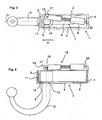
- An exemplary embodiment of the trailer coupling according to the invention consists of a trough-shaped housing 1 with side walls 2,3, a rear wall 4, a front housing wall 5 and a housing bottom 6 with a slotted guide 7.
- On the front housing wall 5 is at the level of a longitudinal axis 10 is a perpendicular to Housing bottom 6 arranged roof edge-shaped trapezoidal nose 11.
- the keyhole-shaped slotted guide 7 is arranged.
- a ball arm 12 protrudes. It is equipped in the region of the housing bottom 6 with a guide groove 13 which engages in the slide guide 7 such that a rotation of the ball arm 12 in the region of a rectangular part 8 of the slotted guide 7 prevents and allowed only in the area of a round part 9 of the slide guide 7.
- the located in the housing 1 part of the ball arm 12 is designed as a rotary axis member 14.
- the Drehachsglied 14 has a cylindrical shape, its diameter is, as well as the diameter of the ball arm 12, greater than the diameter or the inside diameter of the rectangular and round part of the cam guide 8,9 8th
- a groove 15 is arranged, in which the trapezoidal nose 11 engages in the position of use.
- a pivot axis 17 is arranged off-center, on which a bearing eye 19 of a linear drive 18 engages.
- the linear drive 18 is pivotally mounted on the rear wall 4 in a bearing 20.
- Fig. 1 shows the trailer hitch in non-use position in a plan view
- Fig. 2 in a side view.
- the linear drive 18 is fully retracted, the ball arm 12 is retracted with the guide groove 13 in the rectangular part 8 of the slide guide 7.
- the ball arm 12 is parallel to the longitudinal axis 10th
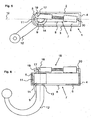
- Fig. 3 shows the hitch in an intermediate position in a plan view, Fig. 4 in a side view.
- the acting on the pivot axis 17 on the Drehachsglied 14 linear drive 18 is extended and has the ball arm 12 in the rectangular part 8 of the guide slot 7 to the round Part 9 of the guide slot 7 pushed in the direction of arrow A until the Drehachsglied 14 abuts against the trapezoidal nose 11 of the front housing wall 5, whereby the linear movement of the ball arm 12 along the longitudinal axis 10 ends.
- the guide groove 13 prevents, as long as it engages in the rectangular part 8 of the guide slot 7, a pivoting of the ball arm 12th
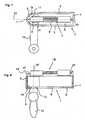
- Fig. 5 shows the trailer hitch in the pivoting movement of the ball arm 12 from the intermediate position to the position of use Fig. 7,8 in a plan view, Fig. 6 in a side view.
- the longitudinal movement of the ball arm 12 is prevented. Since the guide groove 13 on the ball arm 12 now engages in the round part 9 of the slotted guide 7, which is wider than the rectangular part 8, the ball arm 12 can now pivot about the axis of rotation 16. The pivoting is effected by the fact that the linear drive 18 does not act on the axis of rotation 16, but on the eccentric pivot axis 17. The resulting “lever” 21 causes the pivoting 12 upon further extension of the linear drive 18 of the ball arm in the direction of use position.
- Fig. 7 shows the trailer hitch in the position of use in a plan view
- Fig. 8 in a side view.
- Fig. 9 shows in a plan view of the trailer hitch after Fig. 5 in the intermediate position when pivoting in the position of use. To clarify the function of the linear drive 18 as well as the pivot axis 17 is not shown here.
- the guide groove 13 of the ball arm 12 is located in the round part 9 of the slide guide 7, the rotary axis member 14 is located on the trapezoidal nose 11 at.
- the linear actuator 18 can pivot through the eccentric articulation on the pivot axis 17, the Drehachsglied 14 and thus the ball arm 12 in the direction of arrow B until the trapezoidal nose 11 and the groove 15 face in Drehachsglied 14. Due to the further thrust of the linear drive 18, the Drehachsglied 14 and thus the ball arm 12 is still a piece along the longitudinal axis 10 moves linearly until the trapezoidal nose 11 engages the groove 15 and the Drehachsglied 14 rests flat against the front housing wall 5 Thus, the use position reached.
- Fig. 10 shows in a plan view of the device Fig. 7 in the position of use.
- the trapezoidal nose 11 has engaged in the groove 15, the Drehachsglied 14 lies flat against the front housing wall 5 at.
- Forces, which act on the ball arm (ball rod) 12 from outside, for example, by a trailer, are for the most part introduced into the housing 1; only small force components act on the linear drive 18.
Landscapes
- Engineering & Computer Science (AREA)
- Transportation (AREA)
- Mechanical Engineering (AREA)
- Transmission Devices (AREA)
- Medicines Containing Plant Substances (AREA)
- Fuel Cell (AREA)
- Agricultural Machines (AREA)
- Vehicle Cleaning, Maintenance, Repair, Refitting, And Outriggers (AREA)
Claims (9)
- Attelage de remorque pour véhicules motorisés, en particulier des véhicules personnels, avec un bras d'attelage (12) qui porte à une extrémité une pièce de tête relevée pour la fixation amovible d'une remorque et est relié fixement à l'autre extrémité à un organe d'axe rotatif (14) monté mobile dans un boîtier (1), le bras d'attelage (12) pouvant être déplacé en va et vient au moyen d'un dispositif d'avance manuel ou motorisé entre une position d'utilisation dirigée vers l'arrière et une position de non-utilisation placée plus en avant, le mouvement de déplacement étant composé de deux mouvements dans lesquels l'organe d'axe rotatif (14) est déplacé en partant de la position de non-utilisation dans une première section de mouvement dans le boîtier (1) et est pivoté dans une deuxième section de mouvement, de sorte qu'au terme des deux mouvements, lesquels peuvent se superposer, le bras d'attelage (12) occupe la position d'utilisation, caractérisé en ce qu'il présente, pour faire pivoter le bras d'attelage (12), un entraînement linéaire (18) manuel ou motorisé articulé de manière pivotante sur l'organe d'axe rotatif (14) en position excentrée par rapport à un axe de rotation (16) de l'organe d'axe rotatif (14), l'entraînement linéaire (18) déplaçant le bras d'attelage (12) de manière guidée par un dispositif de guidage destiné à guider le bras d'attelage et qui comprend des éléments de guidage ou une coulisse (7) placés/placée à l'extérieur du boîtier (1), jusqu'à ce que le dispositif de guidage libère le bras d'attelage (12) pour son pivotement, et en ce qu'au terme du pivotement, un évidement de l'organe d'axe rotatif (14) glisse dans une contrepartie (11) correspondant à l'évidement, de sorte que le bras d'attelage (12) est immobilisé dans le boîtier (1) en étant relié à l'entraînement linéaire (18) et est empêché de poursuivre sa rotation.
- Attelage de remorque selon la revendication 1, caractérisé en ce que l'évidement (15) comprend une rainure (15) ou un perçage ou un évidement ovale ou trapézoïdal, auquel correspond la contrepartie sur le boîtier (1) à des fins d'immobilisation de l'organe d'axe rotatif (14).
- Attelage de remorque selon la revendication 1 ou 2, caractérisé en ce que le bras d'attelage (12) est immobilisé dans le boîtier (1) sous une pression de l'entraînement linéaire (18) et est empêché de poursuivre sa rotation.
- Attelage de remorque selon l'une des revendications précédentes, caractérisé en ce que le boîtier (1) présente un fond de boîtier continu (6) ou au moins deux parties de fond de boîtier disposées l'une derrière l'autre suivant des angles différents par rapport à l'horizontale.
- Attelage de remorque selon la revendication 1, caractérisé en ce que les éléments de guidage placés à l'extérieur du boîtier (1) sont des tôles directrices ou des rails pour commander le bras d'attelage (12).
- Attelage de remorque selon l'une des revendications précédentes, caractérisé en ce que l'entraînement linéaire (18) est articulé de manière pivotante sur l'organe d'axe rotatif (14) au niveau d'un axe de pivotement (17) formant saillie devant l'organe d'axe rotatif (14) ou d'un élément d'articulation placé à l'intérieur de l'organe d'axe rotatif (14), en particulier un axe de pivotement intégré à l'organe d'axe rotatif (14).
- Attelage de remorque selon l'une des revendications précédentes, caractérisé en ce que le boîtier (1) occupe une position inclinée par rapport au véhicule.
- Attelage de remorque selon l'une des revendications précédentes, caractérisé en ce que le bras d'attelage (12) est mobile dans un ou plusieurs plans inclinés du boîtier (1).
- Attelage de remorque selon l'une des revendications précédentes, caractérisé en ce que l'entraînement linéaire (18) fait pivoter l'organe d'axe rotatif (14) par son articulation excentrée sur celui-ci, jusqu'à ce que l'évidement (15) de l'organe d'axe rotatif (14) et la contrepartie se trouvent en face l'un de l'autre, et en ce que l'organe d'axe rotatif (14) est ensuite déplacé linéairement par une nouvelle course de l'entraînement linéaire (18) le long de l'axe longitudinal (10), jusqu'à ce que la contrepartie (11) s'engage dans l'évidement (15) et que l'organe d'axe rotatif (14) s'appuie contre la paroi antérieure (5) du boîtier.
Applications Claiming Priority (2)
| Application Number | Priority Date | Filing Date | Title |
|---|---|---|---|
| DE202004005806U DE202004005806U1 (de) | 2004-04-08 | 2004-04-08 | Anhängerkupplung |
| DE202004005806U | 2004-04-08 |
Publications (2)
| Publication Number | Publication Date |
|---|---|
| EP1584500A1 EP1584500A1 (fr) | 2005-10-12 |
| EP1584500B1 true EP1584500B1 (fr) | 2009-02-11 |
Family
ID=32892607
Family Applications (1)
| Application Number | Title | Priority Date | Filing Date |
|---|---|---|---|
| EP05005549A Not-in-force EP1584500B1 (fr) | 2004-04-08 | 2005-03-15 | Attelage de remorque |
Country Status (3)
| Country | Link |
|---|---|
| EP (1) | EP1584500B1 (fr) |
| AT (1) | ATE422431T1 (fr) |
| DE (2) | DE202004005806U1 (fr) |
Families Citing this family (6)
| Publication number | Priority date | Publication date | Assignee | Title |
|---|---|---|---|---|
| DE102004045859A1 (de) * | 2004-09-20 | 2006-03-23 | Jaeger Cartronix Gmbh | Manueller Antrieb für eine Anhängerkupplung |
| DE102006045979A1 (de) * | 2006-09-27 | 2008-04-03 | Fac Frank Abels Consulting & Technology Gesellschaft Mbh | Anhängerkupplung |
| CN100519237C (zh) * | 2007-08-28 | 2009-07-29 | 王春江 | 位于牵引工具和拖曳物间的连接装置 |
| DE102017118152B4 (de) | 2017-08-09 | 2020-09-24 | Fac Frank Abels Consulting & Technology Gesellschaft Mbh | Motorisch verschwenkbare Anhängekupplung |
| US11059336B1 (en) * | 2018-04-05 | 2021-07-13 | Charles L. Perry | Retractable hitch adaptor system |
| US20220219500A1 (en) * | 2021-01-11 | 2022-07-14 | Ford Global Technologies, Llc | Pivoting Vehicle Trailer Hitch |
Family Cites Families (14)
| Publication number | Priority date | Publication date | Assignee | Title |
|---|---|---|---|---|
| DE19654867C2 (de) | 1995-09-13 | 1998-01-22 | Cartron Fahrzeugteile Gmbh | Schwenkbare Anhängerkupplung für Kraftfahrzeuge |
| DE19612959A1 (de) | 1996-04-01 | 1997-10-02 | Oris Fahrzeugteile Riehle H | Anhängekupplung |
| SE509538C2 (sv) | 1997-06-19 | 1999-02-08 | Volvo Ab | Dragkroksanordning för motorfordon |
| DE19826618C2 (de) | 1998-06-17 | 2001-05-03 | Peter Rocca | Anhängekupplung |
| US6447000B1 (en) * | 1999-02-05 | 2002-09-10 | Popup Industries, Inc. | Mechanism for retractable gooseneck hitch ball |
| DE19944264A1 (de) | 1999-09-15 | 2001-03-22 | Jaeger Cartronix Gmbh | Anhängerkupplung mit axialem Verfahrweg |
| DE10004523A1 (de) | 2000-02-02 | 2001-08-09 | Fac Frank Abels Consult & Tech | Anhängerkupplung |
| DE10023641B4 (de) * | 2000-05-13 | 2010-04-29 | Westfalia-Automotive Gmbh | Anhängerkupplung |
| DE10023640C2 (de) | 2000-05-13 | 2003-05-08 | Fac Frank Abels Consult & Tech | Anhängerkupplung |
| DE10104185A1 (de) | 2001-01-23 | 2002-07-25 | Fac Frank Abels Consult & Tech | Anhängerkupplung |
| DE10231221A1 (de) * | 2002-07-11 | 2004-01-29 | Dr.Ing.H.C. F. Porsche Ag | Anhängezugvorrichtung |
| DE10243044B4 (de) * | 2002-09-12 | 2016-01-21 | Westfalia-Automotive Gmbh | Anhängerkupplung |
| DE10243045B4 (de) | 2002-09-12 | 2016-01-21 | Westfalia-Automotive Gmbh | Anhängerkupplung |
| DE202004006666U1 (de) * | 2003-12-13 | 2004-08-19 | Fac Frank Abels Consulting & Technology Gesellschaft Mbh | Anhängerkupplung |
-
2004
- 2004-04-08 DE DE202004005806U patent/DE202004005806U1/de not_active Expired - Lifetime
-
2005
- 2005-03-15 DE DE502005006589T patent/DE502005006589D1/de active Active
- 2005-03-15 EP EP05005549A patent/EP1584500B1/fr not_active Not-in-force
- 2005-03-15 AT AT05005549T patent/ATE422431T1/de not_active IP Right Cessation
Also Published As
| Publication number | Publication date |
|---|---|
| DE502005006589D1 (de) | 2009-03-26 |
| DE202004005806U1 (de) | 2004-08-19 |
| ATE422431T1 (de) | 2009-02-15 |
| EP1584500A1 (fr) | 2005-10-12 |
Similar Documents
| Publication | Publication Date | Title |
|---|---|---|
| EP0850147B2 (fr) | Dispositif d'attelage de remorque pour vehicules automobiles | |
| EP1584499B1 (fr) | Attelage de remorque | |
| DE10023640C2 (de) | Anhängerkupplung | |
| EP1880879B1 (fr) | Dispositif d'attelage pivotant pour tracteurs | |
| EP1435305B1 (fr) | Attelage de remorque | |
| EP1584500B1 (fr) | Attelage de remorque | |
| DE102005007430A1 (de) | Befestigungs- und Positioniervorrichtung für einen Fahrzeugsitz | |
| EP1637364A1 (fr) | Attelage de remorque | |
| EP1561610B1 (fr) | Mecanisme d'attelage | |
| DE10243045B4 (de) | Anhängerkupplung | |
| EP1586471B1 (fr) | Attelage de remorque | |
| EP1905617B1 (fr) | Attelage | |
| EP1541385B1 (fr) | Attache remorque | |
| EP1586470B1 (fr) | Attelage de remorque | |
| DE10347817B4 (de) | Anhängekupplung | |
| DE10045296A1 (de) | Anhängerkupplung für Kraftfahrzeuge | |
| EP2657051A1 (fr) | Agencement de couplage pour un support de toit | |
| EP2289743A2 (fr) | Appui de levage | |
| DE102010043207B4 (de) | Anhänger | |
| DE10347816B4 (de) | Anhängekupplung mit lastfreier Drehlagereinrichtung | |
| DE202004006666U1 (de) | Anhängerkupplung | |
| WO2008049569A1 (fr) | Dispositif d'attelage | |
| EP1584498B1 (fr) | Attelage de remorque | |
| DE102004012483B4 (de) | Kupplungseinrichtung zum Verbinden eines Zugfahrzeuges mit einem Anhänger | |
| DE102007047349A1 (de) | Verladevorrichtung |
Legal Events
| Date | Code | Title | Description |
|---|---|---|---|
| PUAI | Public reference made under article 153(3) epc to a published international application that has entered the european phase |
Free format text: ORIGINAL CODE: 0009012 |
|
| AK | Designated contracting states |
Kind code of ref document: A1 Designated state(s): AT BE BG CH CY CZ DE DK EE ES FI FR GB GR HU IE IS IT LI LT LU MC NL PL PT RO SE SI SK TR |
|
| AX | Request for extension of the european patent |
Extension state: AL BA HR LV MK YU |
|
| 17P | Request for examination filed |
Effective date: 20060317 |
|
| AKX | Designation fees paid |
Designated state(s): AT BE BG CH CY CZ DE DK EE ES FI FR GB GR HU IE IS IT LI LT LU MC NL PL PT RO SE SI SK TR |
|
| RAP1 | Party data changed (applicant data changed or rights of an application transferred) |
Owner name: WESTFALIA - AUTOMOTIVE GMBH |
|
| 17Q | First examination report despatched |
Effective date: 20070614 |
|
| GRAP | Despatch of communication of intention to grant a patent |
Free format text: ORIGINAL CODE: EPIDOSNIGR1 |
|
| GRAS | Grant fee paid |
Free format text: ORIGINAL CODE: EPIDOSNIGR3 |
|
| GRAA | (expected) grant |
Free format text: ORIGINAL CODE: 0009210 |
|
| AK | Designated contracting states |
Kind code of ref document: B1 Designated state(s): AT BE BG CH CY CZ DE DK EE ES FI FR GB GR HU IE IS IT LI LT LU MC NL PL PT RO SE SI SK TR |
|
| REG | Reference to a national code |
Ref country code: GB Ref legal event code: FG4D Free format text: NOT ENGLISH |
|
| REG | Reference to a national code |
Ref country code: CH Ref legal event code: EP |
|
| REG | Reference to a national code |
Ref country code: IE Ref legal event code: FG4D Free format text: LANGUAGE OF EP DOCUMENT: GERMAN |
|
| REF | Corresponds to: |
Ref document number: 502005006589 Country of ref document: DE Date of ref document: 20090326 Kind code of ref document: P |
|
| PG25 | Lapsed in a contracting state [announced via postgrant information from national office to epo] |
Ref country code: SI Free format text: LAPSE BECAUSE OF FAILURE TO SUBMIT A TRANSLATION OF THE DESCRIPTION OR TO PAY THE FEE WITHIN THE PRESCRIBED TIME-LIMIT Effective date: 20090211 Ref country code: NL Free format text: LAPSE BECAUSE OF FAILURE TO SUBMIT A TRANSLATION OF THE DESCRIPTION OR TO PAY THE FEE WITHIN THE PRESCRIBED TIME-LIMIT Effective date: 20090211 Ref country code: ES Free format text: LAPSE BECAUSE OF FAILURE TO SUBMIT A TRANSLATION OF THE DESCRIPTION OR TO PAY THE FEE WITHIN THE PRESCRIBED TIME-LIMIT Effective date: 20090522 Ref country code: LT Free format text: LAPSE BECAUSE OF FAILURE TO SUBMIT A TRANSLATION OF THE DESCRIPTION OR TO PAY THE FEE WITHIN THE PRESCRIBED TIME-LIMIT Effective date: 20090211 Ref country code: FI Free format text: LAPSE BECAUSE OF FAILURE TO SUBMIT A TRANSLATION OF THE DESCRIPTION OR TO PAY THE FEE WITHIN THE PRESCRIBED TIME-LIMIT Effective date: 20090211 |
|
| NLV1 | Nl: lapsed or annulled due to failure to fulfill the requirements of art. 29p and 29m of the patents act | ||
| PG25 | Lapsed in a contracting state [announced via postgrant information from national office to epo] |
Ref country code: IS Free format text: LAPSE BECAUSE OF FAILURE TO SUBMIT A TRANSLATION OF THE DESCRIPTION OR TO PAY THE FEE WITHIN THE PRESCRIBED TIME-LIMIT Effective date: 20090611 Ref country code: SE Free format text: LAPSE BECAUSE OF FAILURE TO SUBMIT A TRANSLATION OF THE DESCRIPTION OR TO PAY THE FEE WITHIN THE PRESCRIBED TIME-LIMIT Effective date: 20090511 Ref country code: PL Free format text: LAPSE BECAUSE OF FAILURE TO SUBMIT A TRANSLATION OF THE DESCRIPTION OR TO PAY THE FEE WITHIN THE PRESCRIBED TIME-LIMIT Effective date: 20090211 |
|
| REG | Reference to a national code |
Ref country code: IE Ref legal event code: FD4D |
|
| BERE | Be: lapsed |
Owner name: WESTFALIA - AUTOMOTIVE G.M.B.H. Effective date: 20090331 |
|
| PG25 | Lapsed in a contracting state [announced via postgrant information from national office to epo] |
Ref country code: DK Free format text: LAPSE BECAUSE OF FAILURE TO SUBMIT A TRANSLATION OF THE DESCRIPTION OR TO PAY THE FEE WITHIN THE PRESCRIBED TIME-LIMIT Effective date: 20090211 Ref country code: CZ Free format text: LAPSE BECAUSE OF FAILURE TO SUBMIT A TRANSLATION OF THE DESCRIPTION OR TO PAY THE FEE WITHIN THE PRESCRIBED TIME-LIMIT Effective date: 20090211 Ref country code: PT Free format text: LAPSE BECAUSE OF FAILURE TO SUBMIT A TRANSLATION OF THE DESCRIPTION OR TO PAY THE FEE WITHIN THE PRESCRIBED TIME-LIMIT Effective date: 20090713 Ref country code: IE Free format text: LAPSE BECAUSE OF FAILURE TO SUBMIT A TRANSLATION OF THE DESCRIPTION OR TO PAY THE FEE WITHIN THE PRESCRIBED TIME-LIMIT Effective date: 20090211 Ref country code: EE Free format text: LAPSE BECAUSE OF FAILURE TO SUBMIT A TRANSLATION OF THE DESCRIPTION OR TO PAY THE FEE WITHIN THE PRESCRIBED TIME-LIMIT Effective date: 20090211 Ref country code: MC Free format text: LAPSE BECAUSE OF NON-PAYMENT OF DUE FEES Effective date: 20090331 |
|
| REG | Reference to a national code |
Ref country code: CH Ref legal event code: PL |
|
| PG25 | Lapsed in a contracting state [announced via postgrant information from national office to epo] |
Ref country code: SK Free format text: LAPSE BECAUSE OF FAILURE TO SUBMIT A TRANSLATION OF THE DESCRIPTION OR TO PAY THE FEE WITHIN THE PRESCRIBED TIME-LIMIT Effective date: 20090211 Ref country code: RO Free format text: LAPSE BECAUSE OF FAILURE TO SUBMIT A TRANSLATION OF THE DESCRIPTION OR TO PAY THE FEE WITHIN THE PRESCRIBED TIME-LIMIT Effective date: 20090211 |
|
| PLBE | No opposition filed within time limit |
Free format text: ORIGINAL CODE: 0009261 |
|
| STAA | Information on the status of an ep patent application or granted ep patent |
Free format text: STATUS: NO OPPOSITION FILED WITHIN TIME LIMIT |
|
| 26N | No opposition filed |
Effective date: 20091112 |
|
| GBPC | Gb: european patent ceased through non-payment of renewal fee |
Effective date: 20090511 |
|
| PG25 | Lapsed in a contracting state [announced via postgrant information from national office to epo] |
Ref country code: LI Free format text: LAPSE BECAUSE OF NON-PAYMENT OF DUE FEES Effective date: 20090331 Ref country code: CH Free format text: LAPSE BECAUSE OF NON-PAYMENT OF DUE FEES Effective date: 20090331 Ref country code: BG Free format text: LAPSE BECAUSE OF FAILURE TO SUBMIT A TRANSLATION OF THE DESCRIPTION OR TO PAY THE FEE WITHIN THE PRESCRIBED TIME-LIMIT Effective date: 20090511 |
|
| PG25 | Lapsed in a contracting state [announced via postgrant information from national office to epo] |
Ref country code: BE Free format text: LAPSE BECAUSE OF NON-PAYMENT OF DUE FEES Effective date: 20090331 |
|
| PG25 | Lapsed in a contracting state [announced via postgrant information from national office to epo] |
Ref country code: GB Free format text: LAPSE BECAUSE OF NON-PAYMENT OF DUE FEES Effective date: 20090511 |
|
| PG25 | Lapsed in a contracting state [announced via postgrant information from national office to epo] |
Ref country code: AT Free format text: LAPSE BECAUSE OF NON-PAYMENT OF DUE FEES Effective date: 20090315 |
|
| PG25 | Lapsed in a contracting state [announced via postgrant information from national office to epo] |
Ref country code: GR Free format text: LAPSE BECAUSE OF FAILURE TO SUBMIT A TRANSLATION OF THE DESCRIPTION OR TO PAY THE FEE WITHIN THE PRESCRIBED TIME-LIMIT Effective date: 20090512 |
|
| PG25 | Lapsed in a contracting state [announced via postgrant information from national office to epo] |
Ref country code: IT Free format text: LAPSE BECAUSE OF FAILURE TO SUBMIT A TRANSLATION OF THE DESCRIPTION OR TO PAY THE FEE WITHIN THE PRESCRIBED TIME-LIMIT Effective date: 20090211 |
|
| PG25 | Lapsed in a contracting state [announced via postgrant information from national office to epo] |
Ref country code: LU Free format text: LAPSE BECAUSE OF NON-PAYMENT OF DUE FEES Effective date: 20090315 |
|
| PG25 | Lapsed in a contracting state [announced via postgrant information from national office to epo] |
Ref country code: HU Free format text: LAPSE BECAUSE OF FAILURE TO SUBMIT A TRANSLATION OF THE DESCRIPTION OR TO PAY THE FEE WITHIN THE PRESCRIBED TIME-LIMIT Effective date: 20090812 |
|
| PG25 | Lapsed in a contracting state [announced via postgrant information from national office to epo] |
Ref country code: TR Free format text: LAPSE BECAUSE OF FAILURE TO SUBMIT A TRANSLATION OF THE DESCRIPTION OR TO PAY THE FEE WITHIN THE PRESCRIBED TIME-LIMIT Effective date: 20090211 |
|
| PG25 | Lapsed in a contracting state [announced via postgrant information from national office to epo] |
Ref country code: CY Free format text: LAPSE BECAUSE OF FAILURE TO SUBMIT A TRANSLATION OF THE DESCRIPTION OR TO PAY THE FEE WITHIN THE PRESCRIBED TIME-LIMIT Effective date: 20090211 |
|
| REG | Reference to a national code |
Ref country code: DE Ref legal event code: R082 Ref document number: 502005006589 Country of ref document: DE Representative=s name: BREGENZER, MICHAEL, DIPL.-ING., DE Ref country code: DE Ref legal event code: R082 Ref document number: 502005006589 Country of ref document: DE Representative=s name: PATENTANWAELTE BREGENZER UND REULE PARTNERSCHA, DE |
|
| REG | Reference to a national code |
Ref country code: DE Ref legal event code: R082 Ref document number: 502005006589 Country of ref document: DE Representative=s name: PATENTANWAELTE BREGENZER UND REULE PARTNERSCHA, DE |
|
| REG | Reference to a national code |
Ref country code: FR Ref legal event code: PLFP Year of fee payment: 12 |
|
| REG | Reference to a national code |
Ref country code: FR Ref legal event code: PLFP Year of fee payment: 13 |
|
| REG | Reference to a national code |
Ref country code: FR Ref legal event code: PLFP Year of fee payment: 14 |
|
| PGFP | Annual fee paid to national office [announced via postgrant information from national office to epo] |
Ref country code: DE Payment date: 20220309 Year of fee payment: 18 |
|
| PGFP | Annual fee paid to national office [announced via postgrant information from national office to epo] |
Ref country code: FR Payment date: 20220203 Year of fee payment: 18 |
|
| REG | Reference to a national code |
Ref country code: DE Ref legal event code: R119 Ref document number: 502005006589 Country of ref document: DE |
|
| PG25 | Lapsed in a contracting state [announced via postgrant information from national office to epo] |
Ref country code: FR Free format text: LAPSE BECAUSE OF NON-PAYMENT OF DUE FEES Effective date: 20230331 Ref country code: DE Free format text: LAPSE BECAUSE OF NON-PAYMENT OF DUE FEES Effective date: 20231003 |