EP1584500A1 - Trailer coupling - Google Patents
Trailer coupling Download PDFInfo
- Publication number
- EP1584500A1 EP1584500A1 EP05005549A EP05005549A EP1584500A1 EP 1584500 A1 EP1584500 A1 EP 1584500A1 EP 05005549 A EP05005549 A EP 05005549A EP 05005549 A EP05005549 A EP 05005549A EP 1584500 A1 EP1584500 A1 EP 1584500A1
- Authority
- EP
- European Patent Office
- Prior art keywords
- coupling arm
- housing
- arm
- coupling
- trailer
- Prior art date
- Legal status (The legal status is an assumption and is not a legal conclusion. Google has not performed a legal analysis and makes no representation as to the accuracy of the status listed.)
- Granted
Links
- 230000008878 coupling Effects 0.000 title claims abstract description 23
- 238000010168 coupling process Methods 0.000 title claims abstract description 23
- 238000005859 coupling reaction Methods 0.000 title claims abstract description 23
- 238000004519 manufacturing process Methods 0.000 description 5
- 239000000463 material Substances 0.000 description 2
- 241001236644 Lavinia Species 0.000 description 1
- 208000012886 Vertigo Diseases 0.000 description 1
- 238000010276 construction Methods 0.000 description 1
- 238000000034 method Methods 0.000 description 1
- 230000000284 resting effect Effects 0.000 description 1
Images


Classifications
-
- B—PERFORMING OPERATIONS; TRANSPORTING
- B60—VEHICLES IN GENERAL
- B60D—VEHICLE CONNECTIONS
- B60D1/00—Traction couplings; Hitches; Draw-gear; Towing devices
- B60D1/24—Traction couplings; Hitches; Draw-gear; Towing devices characterised by arrangements for particular functions
- B60D1/246—Traction couplings; Hitches; Draw-gear; Towing devices characterised by arrangements for particular functions for actuating the hitch by powered means
-
- B—PERFORMING OPERATIONS; TRANSPORTING
- B60—VEHICLES IN GENERAL
- B60D—VEHICLE CONNECTIONS
- B60D1/00—Traction couplings; Hitches; Draw-gear; Towing devices
- B60D1/01—Traction couplings or hitches characterised by their type
- B60D1/06—Ball-and-socket hitches, e.g. constructional details, auxiliary devices, their arrangement on the vehicle
-
- B—PERFORMING OPERATIONS; TRANSPORTING
- B60—VEHICLES IN GENERAL
- B60D—VEHICLE CONNECTIONS
- B60D1/00—Traction couplings; Hitches; Draw-gear; Towing devices
- B60D1/48—Traction couplings; Hitches; Draw-gear; Towing devices characterised by the mounting
- B60D1/54—Traction couplings; Hitches; Draw-gear; Towing devices characterised by the mounting collapsible or retractable when not in use, e.g. hide-away hitches
Definitions
- the invention relates to a device for lowering and pivoting a coupling arm in a towing hitch for motor vehicles, in which one provided with a ball Clutch arm from a non-visible from outside the vehicle rest position in a suitable operating position for attaching a trailer motor or manually driven is moved.
- a motor-driven To create trailer hitch which is particularly simple and inexpensive to manufacture. This is achieved in that in the hitch according to the invention no pivot bearing, Locking devices or other components with high manufacturing accuracy for Application, but in which the moving parts within a housing shifted an inclined plane and without using a pivot bearing via a slotted guide transported into the position of use and there by a spindle on the principle of Vices are clamped. Due to the angle of the inclined plane is the Drop height of the ball arm structurally adapted to the respective vehicle.
- An exemplary embodiment of the invention trailer hitch consists of a trough-shaped housing (1) with the side walls (2,3), the rear housing wall (4), the front housing wall (5) and the housing bottom (6) with the slotted guide (7).
- At the front housing wall (5) is located at the level of the longitudinal axis (8) perpendicular to the housing bottom (6) arranged roof edge-shaped trapezoidal nose (11).
- In the housing bottom (6) a keyhole-shaped slotted guide (7) is arranged. Through the slotted guide (7) in the housing bottom (6) of the ball arm (12) protrudes.
- the in the housing (1) located part of the ball arm (12) is designed as Drehachsglied (14).
- the Drehachsglied (14) has a cylindrical shape, its diameter, as well as the diameter of the ball arm (12), greater than the diameter or the inside diameter of the rectangular and round part (8,9) of the slotted guide (7).
- the linear drive (18) is pivotally mounted on the housing rear wall (4) in the bearing (20).
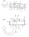
- Fig. 1 shows the trailer hitch in non-use position in a plan view
- Fig. 2 in a side view.
- the linear drive (18) is fully retracted
- the ball arm (12) is retracted with the guide groove (13) in the rectangular part (8) of the slotted guide (7).
- the ball arm (7) is parallel to the longitudinal axis (10).
- Fig. 3 shows the hitch in an intermediate position in a plan view, Fig. 4, in a side view.
- the on the pivot axis (17) on the Drehachsglied (14) acting linear drive (18) is extended and has the ball arm (12) in the rectangular part (8) of the slotted guide (7) to the round part (9) of the slotted guide (7 ) pushed in the direction of arrow A until the Drehachsglied (14) against the trapezoidal nose (11) of the front housing wall (5) abuts, whereby the lincare movement of the ball arm (12) along the longitudinal axis (10) ends.
- the guide groove (13) prevents, as long as it engages in the rectangular part (8) of the slotted guide (7), a pivoting of the ball arm (7).
- Fig. 5 shows the trailer hitch in the pivoting movement of the ball arm (12) from the intermediate position to the position of use of FIG. 7,8 in a plan view, Fig. 6 in a side view.
- the longitudinal movement of the ball arm (12) is prevented.
- the guide groove (13) on the ball arm (12) now engages in the round part (9) of the slotted guide (7), which is wider than the rectangular part (8), the ball arm (7) can now about the axis of rotation (16) swing.
- the pivoting is effected by the fact that the linear drive (18) does not act on the axis of rotation (16), but on the off-center pivot axis (17).
- the resulting “lever” (21) causes, upon further extension of the linear drive (18) of the ball arm (12) pivots in the direction of use position.
- Fig. 7 shows the trailer hitch in the position of use in a plan view
- Fig. 8 in a side view.
- the ball arm (12) has performed the pivoting movement shown in Fig. 5.6 at an angle of approximately 90 °, are Trapeznaae (11) and groove (15) opposite.
- the ball arm (12) is moved linearly along the longitudinal axis (10) until the trapezoidal lug (11) engages in the groove (15) and the rotary axis member (14) on the front housing wall (5) lies flat.
- the radius (23) of the Drehachsgliedes (14) and the radius (24) of the semicircular front housing wall (5) are equal.
- Fig. 9 shows in a plan view of the trailer hitch of FIG. 5 in the intermediate position when pivoting in the position of use.
- the guide groove (13) of the ball arm (12) is in the round part (9) of the Kulissenbind tion (7), the Drehachsglied (14) is located on the trapezoidal nose (11).
- the linear drive (18) by the eccentric articulation on the pivot axis (17) pivot the Drehachsglied (14) and thus the ball arm (12) in the direction of arrow B until the trapezoidal nose (11) and the groove (15) in the rotary axis member (14) face.
- FIG. 10 shows a plan view of the device according to FIG. 7 in the position of use.
- the trapezoidal lug (11) has engaged in the groove (15), the Drehachsglied (14) lies flat against the front housing wall (5).
- Forces, which act on the outside of the ball rod (12), for example, by an on trailer, are for the most part introduced into the housing (1) on the linear drive (18) act only small force components.
Landscapes
- Engineering & Computer Science (AREA)
- Transportation (AREA)
- Mechanical Engineering (AREA)
- Transmission Devices (AREA)
- Medicines Containing Plant Substances (AREA)
- Fuel Cell (AREA)
- Vehicle Cleaning, Maintenance, Repair, Refitting, And Outriggers (AREA)
- Agricultural Machines (AREA)
Abstract
Description
Die Erfindung betrifft eine Vorrichtung zum Absenken und Schwenken eines Kupplungsarmes in einer Anhängekupplung für Kraftfahrzeuge, bei der ein mit einer Kugel versehener Kupplungsarm aus einer von außerhalb des Kraftfahrzeuges nicht sichtbaren Ruhestellung in eine zum Befestigen eines Anhängers geeignete Betriebsstellung motorisch oder manuell angetrieben bewegt wird.The invention relates to a device for lowering and pivoting a coupling arm in a towing hitch for motor vehicles, in which one provided with a ball Clutch arm from a non-visible from outside the vehicle rest position in a suitable operating position for attaching a trailer motor or manually driven is moved.
Es sind verschiedene Ausführungsformen solcher motorisch angetriebener Anhängekupplungen bekannt, z.B. aus der DE 198 26 618, DE 199 44 264 und DE 100 04 523, bei denen eine senkrecht stehende Kugelstange durch motorischen Antrieb zunächst axial nach unten bewegt werden, so daß die Kugel der Kugelstange unterhalb des Stoßfängers liegt, danach wird die Kugelstange um ca. 90° seitlich verdreht und anschließend motorisch wieder angehoben, bis die Kugelstange sich in der Betriebsstellung befindet. Diese Ausführungsformen haben folgende Nachteile:
- Die Bodenfreiheit reicht (je nach Fahrzeugtyp) gelegentlich nicht aus, besonders wenn das Fahrzeug über einer Bordsteinkante steht
- Die senkrecht angeordnete Kugelstange hat eine Bauform, die bei modernen Fahrzeugen mit besonders niedrig liegender Kofferraumkante nicht in das Fahrzeug integriert werden kann
- Aufwendige Konstruktion - teilweise mit 2 Motoren - um die drei Bewegungsschritte Senken, Schwenken, Heben zu realisieren.
- Aufwendige Steuerung der Bewegungsschritte entweder mechanisch oder elektrisch
- Paßgenauc und damit teure Führungen erforderlich, die wegen der eingeleiteten Betriebskräfte teure Materialien und Bearbeitungsverfahren notwendig machen.
- The ground clearance is sometimes insufficient (depending on the type of vehicle), especially when the vehicle is over a curb
- The vertically arranged ball bar has a design that can not be integrated into the vehicle in modern vehicles with a particularly low-lying trunk edge
- Elaborate construction - partly with 2 motors - to realize the three steps of lowering, swiveling, lifting.
- Elaborate control of the movement steps either mechanically or electrically
- Paßgenauc and thus expensive guides required that make expensive materials and processing necessary because of the initiated operating forces.
Es sind weitere Ausführungsformen bekannt, bei denen die Kugelstange an einem fahrzeugfesten Drehlager angeordnet sind und durch einen Motor die Kugelstange aus einer unterhalb des Fahrzeugbodens befindlichen Ruhestellung in die Betriebsstellung geschwenkt wird, wie z.B. in DE 196 54 867 und DE 196 12 959 oder WO 98/57 813 beschrieben. Diese Ausführungsformen haben folgende Nachteile:
- Die Bodenfreiheit reicht bei bestimmten Ausführungformen und Fahrzeugen ebenfalls nicht aus.
- Bei einigen Fahrzeugformen sind sie wegen der Art des Fahrzeugbodens nur schwer oder gar nicht zu integrieren.
- Die Getriebemotoren sind hohen Belastungen ausgesetzt, wodurch sie aufwendig und teuer werden. Es sind bei bestimmten Ausführungsformen zum Festsetzen der Kugelstange zusätzliche Verriegelungsvorrichtungen erforderlich, die starkem Verschleiß unterliegen und teuer in der Herstellung sind.
- Die Hauptschwenklager unterliegen starken Betriebskräften und müssen daher in aufwendigen und teuren Techniken hergestellt werden.
- The ground clearance is also insufficient for certain designs and vehicles.
- In some vehicle forms, they are difficult or impossible to integrate due to the nature of the vehicle floor.
- The geared motors are exposed to high loads, which makes them expensive and expensive. There are additional locking devices required in certain embodiments for fixing the ball rod, which are subject to heavy wear and are expensive to manufacture.
- The main pivot bearings are subject to heavy operating forces and must therefore be manufactured in complex and expensive techniques.
Es sind schließlich Ausführungsformen bekannt, z.B. DE 100 23 640 und DE 101 04 185, bei denen die Kugelstange schwenkbar in einem Lagerblock sitzt, wobei der Lagerblock selber um eine in Fahrzeugrichtung angeordnete Achse schwenken kann, wodurch eine senkende und danach schwenkende Bewegung erzeugt wird. Diese Ausführungsform, die sich zwar sehr gut in Fahrzeuge integrieren läßt, hat dennoch folgende Nachteile:
- Zur Realisierung der Bewegung sind unter
Umständen 2 Motoren erforderlich - Es gibt wiederum drei Bewegungsschritte - Senken - Drehen - Heben - dazu ist eine spezielle Steuerung erforderlich
- Die Herstellung ist wegen zweier großer, die ganz Last aufnehmenden Lager aufwendig und teuer.
- To realize the movement, 2 motors may be required
- There are again three movement steps - lowering - turning - lifting - this requires a special control
- The production is complicated and expensive because of two large, the very load receiving bearing.
Nachdem verschiedene motorisch angetriebene Anhängekupplungen mittlerweile produziert werden, und es sich herausgestellt hat, daß alle bekannten Typen in der Herstellung für den automobilen Massenmarkt zu teuer sind, ist es Zweck der Erfindung, eine motorisch angetriebene Anhängekupplung zu schaffen, die besonders einfach und billig in der Herstellung ist. Dieses wird dadurch erreicht, daß bei der erfindungsgemäßen Anhängekupplung keine Drehlager, Verriegelungsvorrichtungen oder andere Bauteile mit hoher Fertigungsgenauheit zur Anwendung kommen, sondern in dem die bewegenden Teile innerhalb eines Gehäuses auf einer schiefen Ebene verschoben und ohne Verwendung eines Drehlagers über eine Kulissenführung in die Gebrauchsstellung befördert und dort durch eine Spindel nach dem Prinzip des Schraubstocks festgeklemmt werden. Durch den Anstellwinkel der schiefen Ebene wird die Absenkhöhe des Kugelarmes konstruktiv auf das jeweilige Fahrzeug angepasst.After various motor-driven trailer hitches now produced and it has been found that all known types in the manufacture for the automotive mass market are too expensive, it is purpose of the invention, a motor-driven To create trailer hitch, which is particularly simple and inexpensive to manufacture. This is achieved in that in the hitch according to the invention no pivot bearing, Locking devices or other components with high manufacturing accuracy for Application, but in which the moving parts within a housing shifted an inclined plane and without using a pivot bearing via a slotted guide transported into the position of use and there by a spindle on the principle of Vices are clamped. Due to the angle of the inclined plane is the Drop height of the ball arm structurally adapted to the respective vehicle.
Ein Ausführungsbeispiel der Erfindung ist in den folgenden Abbildungen dargestellt. Aus Gründen der Übersichtlichkeit wurde auf die Darstellung des Trägers, mit dem die Anhängerkupplung am Fahrzeug befestigt wird, verzichtet. Ebenso ist die Deckplatte des Gehäuses der Anhängerkupplung nicht dargestellt, da sie den Blick auf die Funktionsbaugruppen verbirgt.An embodiment of the invention is shown in the following figures. Out For reasons of clarity was based on the presentation of the carrier with which the trailer hitch attached to the vehicle is omitted. Likewise, the cover plate of the housing is the Trailer hitch not shown because it hides the view of the function modules.
Eine beispielhafte Ausführung der erfindungsgeäßen Anhängerkupplung besteht aus einem
wannenförmigen Gehäuse (1) mit den Seitenwänden (2,3), der Gehäuserückwand (4), der
vorderen Gehäusewand (5) sowie dem Gehäuseboden (6) mit der Kulissenführung (7). An der
vorderen Gehäusewand (5) befindet sich in Höhe der Längsachse (8) eine senkrecht zum Gehäuseboden
(6) angeordnete dachkantförmige Trapeznase (11). Im Gehäuseboden (6) ist eine
schlüssellochförmige Kulissenführung (7) angeordnet.
Durch die Kulissenführung (7) im Gehäuseboden (6) ragt der Kugelarm (12) hindurch. Er ist
im Bereich des Gehäusebodens (6) mit einer Führungsnut (13) ausgestattet, welche derart in
die Kulissenführung (7) eingreift, daß eine Drehung des Kugelarmes (12) im Bereich des
rechteckigen Teiles (8) der Kulissenführung (7) verhindert und nur im Bereich des runden
Teiles (9) der Kulissenführung (7) erlaubt.
Der sich im Gehäuse (1) befindliche Teil des Kugelarmes (12) ist als Drehachsglied (14) ausgeführt.
Das Drehachsglied (14) besitzt eine zylindrische Form, sein Durchmesser ist, ebenso
wie der Durchmesser des Kugelarmes (12), größer als der Durchmesser bzw. die lichte Weite
des rechteckigen und runden Teiles (8,9) der Kulissenführung (7).
An der Seite des Drehachsgliedes (14) ist senkrecht, also parallell zur Drehachse (16) des Kugelarmes
(12), eine Nut (15) angeordnet, in welche in der Gebrauchsstellung die Trapeznase
(11) eingreift.
An der Oberseite des Drehachsgliedes (14) ist außermittig eine Schwenkachse (17) angeord
net, an der das Lagerauge (19) eines Linearantriebes (18) angreift. Der Linearantrieb (18) ist
an der Gehäuserückwand (4) im Lager (20) schwenkbar gelagert.An exemplary embodiment of the invention trailer hitch consists of a trough-shaped housing (1) with the side walls (2,3), the rear housing wall (4), the front housing wall (5) and the housing bottom (6) with the slotted guide (7). At the front housing wall (5) is located at the level of the longitudinal axis (8) perpendicular to the housing bottom (6) arranged roof edge-shaped trapezoidal nose (11). In the housing bottom (6) a keyhole-shaped slotted guide (7) is arranged.
Through the slotted guide (7) in the housing bottom (6) of the ball arm (12) protrudes. It is in the region of the housing bottom (6) equipped with a guide groove (13) which engages in the slotted guide (7), that rotation of the ball arm (12) in the region of the rectangular part (8) of the slide guide (7) prevents and only in the region of the round part (9) of the slide guide (7) allowed.
The in the housing (1) located part of the ball arm (12) is designed as Drehachsglied (14). The Drehachsglied (14) has a cylindrical shape, its diameter, as well as the diameter of the ball arm (12), greater than the diameter or the inside diameter of the rectangular and round part (8,9) of the slotted guide (7).
On the side of the Drehachsgliedes (14) is perpendicular, ie parallel to the axis of rotation (16) of the ball arm (12), a groove (15) arranged in which in the position of use, the trapezoidal nose (11) engages.
At the top of the Drehachsgliedes (14) off-center a pivot axis (17) angeord net, on which the bearing eye (19) of a linear drive (18) engages. The linear drive (18) is pivotally mounted on the housing rear wall (4) in the bearing (20).
Anhand der Figuren 1 bis 8 wird die Funktion der Erfindung erläutert. The function of the invention will be explained with reference to FIGS. 1 to 8.
Fig. 1 zeigt die Anhängerkupplung in Nichtgebrauchsstellung in einer Draufsicht, Fig. 2 in
einer Seitenansicht.
Der Linearantrieb (18) ist ganz eingefahren, der Kugelarm (12) ist mit der Führungsnut (13)
in den rechteckigen Teil (8) der Kulissenführung (7) zurückgezogen. Der Kugelarm (7) steht
parallel zur Längsachse (10).Fig. 1 shows the trailer hitch in non-use position in a plan view, Fig. 2 in a side view.
The linear drive (18) is fully retracted, the ball arm (12) is retracted with the guide groove (13) in the rectangular part (8) of the slotted guide (7). The ball arm (7) is parallel to the longitudinal axis (10).
Fig. 3 zeigt die Anhängekupplung in einer Zwischenstellung in einer Draufsicht, Fig. 4, in
einer Seitenansicht.
Der an der Schwenkachse (17) am Drehachsglied (14) angreifende Linearantrieb (18) ist ausgefahren
und hat den Kugelarm (12) in dem rechteckigen Teil (8) der Kulissenführung (7) bis
in den runden Teil (9) der Kulissenführung (7) in Pfeilrichtung A geschoben, bis das Drehachsglied
(14) gegen die Trapeznase (11) der vorderen Gehäusewand (5) anschlagt, wodurch
die lincare Bewegung des Kugelarmes (12) entlang dcr Längsachse (10) endet. Die Führungsnut
(13) verhindert, solange sie in den rechteckigen Teil (8) der Kulissenführung (7) eingreift,
ein Schwenken des Kugelarmes (7).Fig. 3 shows the hitch in an intermediate position in a plan view, Fig. 4, in a side view.
The on the pivot axis (17) on the Drehachsglied (14) acting linear drive (18) is extended and has the ball arm (12) in the rectangular part (8) of the slotted guide (7) to the round part (9) of the slotted guide (7 ) pushed in the direction of arrow A until the Drehachsglied (14) against the trapezoidal nose (11) of the front housing wall (5) abuts, whereby the lincare movement of the ball arm (12) along the longitudinal axis (10) ends. The guide groove (13) prevents, as long as it engages in the rectangular part (8) of the slotted guide (7), a pivoting of the ball arm (7).
Fig. 5 zeigt die Anhängerkupplung in der Schwenkbewegung des Kugelarmes (12) aus der
Zwischenstellung in die Gebrauchsstellung nach Fig. 7,8 in einer Draufsicht, Fig. 6 in einer
Seitenansicht.
Durch den Anschlag des Drehachsgliedes (14) an der Trapeznase (11) ist die Längsbewegung
des Kugelarmes (12) verhindert. Da die Führungsnut (13) am Kugelarm (12) nun in den runden
Teil (9) der Kulissenführung (7) eingreift, welcher breiter ist als der rechteckige Teil (8),
kann der Kugelarm (7) nun um die Drehachse (16) schwenken. Das Schwenken wird dadurch
bewirkt, daß der Linearantrieb (18) nicht an der Drehachse (16) angreift, sondern an der außermittigen
Schwenkachse (17). Der dadurch entstehende "Hebel" (21) bewirkt, das bei weiterem
Ausfahren des Linearantriebes (18) der Kugelarm (12) in Richtung Gebrauchsstellung
schwenkt.Fig. 5 shows the trailer hitch in the pivoting movement of the ball arm (12) from the intermediate position to the position of use of FIG. 7,8 in a plan view, Fig. 6 in a side view.
By the stop of the Drehachsgliedes (14) on the trapezoidal nose (11), the longitudinal movement of the ball arm (12) is prevented. Since the guide groove (13) on the ball arm (12) now engages in the round part (9) of the slotted guide (7), which is wider than the rectangular part (8), the ball arm (7) can now about the axis of rotation (16) swing. The pivoting is effected by the fact that the linear drive (18) does not act on the axis of rotation (16), but on the off-center pivot axis (17). The resulting "lever" (21) causes, upon further extension of the linear drive (18) of the ball arm (12) pivots in the direction of use position.
Fig. 7 zeigt die Anhängerkupplung in der Gebrauchsstellung in einer Draufsicht, Fig. 8 in
einer Seitenansicht.
Wenn der Kugelarm (12) die in Fig. 5,6 gezeigte Schwenkbewegung mit einem Winkel von
ca. 90° durchgeführt hat, stehen sich Trapeznaae (11) und Nut (15) gegenüber. Durch die
weitere Schubbewegung des Lincarantriebes (18) wird der Kugelarm (12) noch ein Stück
entlang der Längsachse (10) linear bewegt, bis die Trapeznase (11) in die Nut (15) eingreift
und das Drehachsglied (14) an der vorderen Gehäusewand (5) flächig anliegt. Der Radius (23)
des Drehachsgliedes (14) und der Radius (24) der halbkreisförmigen vorderen Gehäusewand
(5) sind gleich groß. Dadurch wird, solange der Linearantrieb (18) das Drehachsglied (14) in
der Gebrauchsstellung hält, der Kugelarm (12) verdrehfest und unverschiebbar in der Gebrauchsstellung
gehalten. Kräfte, welche von außen auf den Kugelarm (12) einwirken, werden
zum Großteil in das Gehäuse (1) und nur zu einem geringen Teil in den Linearantrieb (18)
eingeleitet.Fig. 7 shows the trailer hitch in the position of use in a plan view, Fig. 8 in a side view.
If the ball arm (12) has performed the pivoting movement shown in Fig. 5.6 at an angle of approximately 90 °, are Trapeznaae (11) and groove (15) opposite. As a result of the further thrust movement of the Lincar drive (18), the ball arm (12) is moved linearly along the longitudinal axis (10) until the trapezoidal lug (11) engages in the groove (15) and the rotary axis member (14) on the front housing wall (5) lies flat. The radius (23) of the Drehachsgliedes (14) and the radius (24) of the semicircular front housing wall (5) are equal. As a result, as long as the linear drive (18) holds the Drehachsglied (14) in the position of use, the ball arm (12) held rotationally and immovably in the position of use. Forces, which act on the ball arm (12) from the outside, are for the most part introduced into the housing (1) and only to a small extent into the linear drive (18).
Fig. 9 zeigt in einer Draufsicht die Anhängerkupplung nach Fig. 5 in der Zwischenstellung
beim Schwenken in die Gebrauchsstellung. Zur Verdeutlichung der Funktion ist der Linearantrieb
(18) ebenso wie die Schwenkachse (19) hier nicht dargestellt.
Die Führungsnut (13) des Kugelarmes (12) befindet sich im runden Teil (9) der Kulissenfüh
rung (7), das Drehachsglied (14) liegt an der Trapeznase (11) an. Wie bereits bei Fig. 5 erläutert,
kann der Linearantrieb (18) durch die außermittige Anlenkung an der Schwenkachse (17)
das Drehachsglied (14) und damit den Kugelarm (12) in Pfeilrichtung B schwenken, bis die
Trapeznase (11) und die Nut (15) im Drehachsglied (14) gegenüberstehen. Durch den weiteren
Schub des Linearantriebes (18) wird das Drehachsglied (14) und damit der Kugelarm
(12) noch ein Stück entlang der Längsachse (10) linear bewegt, bis die Trapeznase (11) in die
Nut (15) eingreift und das Drehachsglied (14) an der vorderen Gehäusewand (5) flächig anliegt
Damit ist die Gebrauchsstellung erreicht.Fig. 9 shows in a plan view of the trailer hitch of FIG. 5 in the intermediate position when pivoting in the position of use. To clarify the function of the linear drive (18) as well as the pivot axis (19) is not shown here.
The guide groove (13) of the ball arm (12) is in the round part (9) of the Kulissenfüh tion (7), the Drehachsglied (14) is located on the trapezoidal nose (11). As already explained in Fig. 5, the linear drive (18) by the eccentric articulation on the pivot axis (17) pivot the Drehachsglied (14) and thus the ball arm (12) in the direction of arrow B until the trapezoidal nose (11) and the groove (15) in the rotary axis member (14) face. Due to the further thrust of the linear drive (18) the Drehachsglied (14) and thus the ball arm (12) is still a piece along the longitudinal axis (10) moves linearly until the trapezoidal nose (11) engages in the groove (15) and the Drehachsglied (14) on the front housing wall (5) lies flat against the position of use is reached.
Fig. 10 zeigt in einer Draufsicht die Vorrichtung nach Fig. 7 in der Gebrauchsstellung.
Die Trapeznase (11) hat in die Nut (15) eingegriffen, das Drehachsglied (14) liegt flächig an
der vorderen Gehäusewand (5) an. Kräfte, welche von außen beispielsweise durch einen An
hänger auf die Kugelstange (12) einwirken, werden zum Großteil in das Gehäuse (1) eingeleitet,
auf den Linearantrieb (18) wirken nur kleine Kraftanteile.FIG. 10 shows a plan view of the device according to FIG. 7 in the position of use. FIG.
The trapezoidal lug (11) has engaged in the groove (15), the Drehachsglied (14) lies flat against the front housing wall (5). Forces, which act on the outside of the ball rod (12), for example, by an on trailer, are for the most part introduced into the housing (1) on the linear drive (18) act only small force components.
Claims (5)
Applications Claiming Priority (2)
| Application Number | Priority Date | Filing Date | Title |
|---|---|---|---|
| DE202004005806U DE202004005806U1 (en) | 2004-04-08 | 2004-04-08 | trailer hitch |
| DE202004005806U | 2004-04-08 |
Publications (2)
| Publication Number | Publication Date |
|---|---|
| EP1584500A1 true EP1584500A1 (en) | 2005-10-12 |
| EP1584500B1 EP1584500B1 (en) | 2009-02-11 |
Family
ID=32892607
Family Applications (1)
| Application Number | Title | Priority Date | Filing Date |
|---|---|---|---|
| EP05005549A Not-in-force EP1584500B1 (en) | 2004-04-08 | 2005-03-15 | Trailer coupling |
Country Status (3)
| Country | Link |
|---|---|
| EP (1) | EP1584500B1 (en) |
| AT (1) | ATE422431T1 (en) |
| DE (2) | DE202004005806U1 (en) |
Cited By (4)
| Publication number | Priority date | Publication date | Assignee | Title |
|---|---|---|---|---|
| CN100519237C (en) * | 2007-08-28 | 2009-07-29 | 王春江 | Coupling device between traction tool and trailer like |
| EP3441243B1 (en) | 2017-08-09 | 2020-07-01 | FAC Frank Abels Consulting & Technology GmbH | Motor-driven pivotable trailer coupling |
| US11059336B1 (en) * | 2018-04-05 | 2021-07-13 | Charles L. Perry | Retractable hitch adaptor system |
| US20220219500A1 (en) * | 2021-01-11 | 2022-07-14 | Ford Global Technologies, Llc | Pivoting Vehicle Trailer Hitch |
Families Citing this family (2)
| Publication number | Priority date | Publication date | Assignee | Title |
|---|---|---|---|---|
| DE102004045859A1 (en) * | 2004-09-20 | 2006-03-23 | Jaeger Cartronix Gmbh | Manual drive for a trailer hitch |
| DE102006045979A1 (en) * | 2006-09-27 | 2008-04-03 | Fac Frank Abels Consulting & Technology Gesellschaft Mbh | trailer hitch |
Citations (14)
| Publication number | Priority date | Publication date | Assignee | Title |
|---|---|---|---|---|
| DE19654867A1 (en) | 1995-09-13 | 1997-08-28 | Cartron Fahrzeugteile Gmbh | Swiveling trailer hitch for motor vehicles |
| DE19612959A1 (en) | 1996-04-01 | 1997-10-02 | Oris Fahrzeugteile Riehle H | Trailer coupling |
| WO1998057813A1 (en) | 1997-06-19 | 1998-12-23 | Volvo Personvagnar Ab | Hitching means for vehicles |
| DE19826618A1 (en) | 1998-06-17 | 1999-12-23 | Peter Rocca | Swivel mounted and vertically movable tow bar can be completely hidden inside bumper unit |
| DE19944264A1 (en) | 1999-09-15 | 2001-03-22 | Jaeger Cartronix Gmbh | Trailer coupling with axial travel |
| DE10004523A1 (en) | 2000-02-02 | 2001-08-09 | Fac Frank Abels Consult & Tech | Trailer coupling for car, coupling arm of which can be retracted into bumper (fender) |
| DE10023640A1 (en) | 2000-05-13 | 2001-11-15 | Fac Frank Abels Consult & Tech | trailer hitch |
| DE10023641A1 (en) * | 2000-05-13 | 2001-11-15 | Fac Frank Abels Consult & Tech | Trailer coupling for private motor vehicles has motor spindle drive unit with casing containing electric drive motor, and rotating threaded spindle protruding from casing and engaging with pivot-mounted stationary spindle nut |
| DE10104185A1 (en) | 2001-01-23 | 2002-07-25 | Fac Frank Abels Consult & Tech | trailer hitch |
| US6447000B1 (en) * | 1999-02-05 | 2002-09-10 | Popup Industries, Inc. | Mechanism for retractable gooseneck hitch ball |
| EP1380445A1 (en) * | 2002-07-11 | 2004-01-14 | Dr.Ing. h.c.F. Porsche Aktiengesellschaft | Trailer traction device |
| DE10243045A1 (en) | 2002-09-12 | 2004-03-25 | Fac Frank Abels Consulting & Technology Gesellschaft Mbh | Towing unit for vehicle to be stored behind rear cover and to be swiveled and pulled into towing position |
| DE10243044A1 (en) * | 2002-09-12 | 2004-05-13 | Fac Frank Abels Consulting & Technology Gesellschaft Mbh | Trailer coupling has guide track on shaft element or bearing component and with linear guiding section guiding shaft in axial direction, and rotational guiding section guiding shaft element in rotational direction |
| DE202004006666U1 (en) * | 2003-12-13 | 2004-08-19 | Fac Frank Abels Consulting & Technology Gesellschaft Mbh | Motor vehicle trailer coupling has hitch arm with motorized retractable mounting and rotary bearing to support arm with respect to chassis |
-
2004
- 2004-04-08 DE DE202004005806U patent/DE202004005806U1/en not_active Expired - Lifetime
-
2005
- 2005-03-15 EP EP05005549A patent/EP1584500B1/en not_active Not-in-force
- 2005-03-15 DE DE502005006589T patent/DE502005006589D1/en active Active
- 2005-03-15 AT AT05005549T patent/ATE422431T1/en not_active IP Right Cessation
Patent Citations (14)
| Publication number | Priority date | Publication date | Assignee | Title |
|---|---|---|---|---|
| DE19654867A1 (en) | 1995-09-13 | 1997-08-28 | Cartron Fahrzeugteile Gmbh | Swiveling trailer hitch for motor vehicles |
| DE19612959A1 (en) | 1996-04-01 | 1997-10-02 | Oris Fahrzeugteile Riehle H | Trailer coupling |
| WO1998057813A1 (en) | 1997-06-19 | 1998-12-23 | Volvo Personvagnar Ab | Hitching means for vehicles |
| DE19826618A1 (en) | 1998-06-17 | 1999-12-23 | Peter Rocca | Swivel mounted and vertically movable tow bar can be completely hidden inside bumper unit |
| US6447000B1 (en) * | 1999-02-05 | 2002-09-10 | Popup Industries, Inc. | Mechanism for retractable gooseneck hitch ball |
| DE19944264A1 (en) | 1999-09-15 | 2001-03-22 | Jaeger Cartronix Gmbh | Trailer coupling with axial travel |
| DE10004523A1 (en) | 2000-02-02 | 2001-08-09 | Fac Frank Abels Consult & Tech | Trailer coupling for car, coupling arm of which can be retracted into bumper (fender) |
| DE10023640A1 (en) | 2000-05-13 | 2001-11-15 | Fac Frank Abels Consult & Tech | trailer hitch |
| DE10023641A1 (en) * | 2000-05-13 | 2001-11-15 | Fac Frank Abels Consult & Tech | Trailer coupling for private motor vehicles has motor spindle drive unit with casing containing electric drive motor, and rotating threaded spindle protruding from casing and engaging with pivot-mounted stationary spindle nut |
| DE10104185A1 (en) | 2001-01-23 | 2002-07-25 | Fac Frank Abels Consult & Tech | trailer hitch |
| EP1380445A1 (en) * | 2002-07-11 | 2004-01-14 | Dr.Ing. h.c.F. Porsche Aktiengesellschaft | Trailer traction device |
| DE10243045A1 (en) | 2002-09-12 | 2004-03-25 | Fac Frank Abels Consulting & Technology Gesellschaft Mbh | Towing unit for vehicle to be stored behind rear cover and to be swiveled and pulled into towing position |
| DE10243044A1 (en) * | 2002-09-12 | 2004-05-13 | Fac Frank Abels Consulting & Technology Gesellschaft Mbh | Trailer coupling has guide track on shaft element or bearing component and with linear guiding section guiding shaft in axial direction, and rotational guiding section guiding shaft element in rotational direction |
| DE202004006666U1 (en) * | 2003-12-13 | 2004-08-19 | Fac Frank Abels Consulting & Technology Gesellschaft Mbh | Motor vehicle trailer coupling has hitch arm with motorized retractable mounting and rotary bearing to support arm with respect to chassis |
Cited By (6)
| Publication number | Priority date | Publication date | Assignee | Title |
|---|---|---|---|---|
| CN100519237C (en) * | 2007-08-28 | 2009-07-29 | 王春江 | Coupling device between traction tool and trailer like |
| EP3441243B1 (en) | 2017-08-09 | 2020-07-01 | FAC Frank Abels Consulting & Technology GmbH | Motor-driven pivotable trailer coupling |
| EP3441243B2 (en) † | 2017-08-09 | 2023-08-09 | FAC Frank Abels Consulting & Technology GmbH | Motor-driven pivotable trailer coupling |
| US11059336B1 (en) * | 2018-04-05 | 2021-07-13 | Charles L. Perry | Retractable hitch adaptor system |
| US20220219500A1 (en) * | 2021-01-11 | 2022-07-14 | Ford Global Technologies, Llc | Pivoting Vehicle Trailer Hitch |
| US12036831B2 (en) * | 2021-01-11 | 2024-07-16 | Ford Global Technologies, Llc | Pivoting vehicle trailer hitch |
Also Published As
| Publication number | Publication date |
|---|---|
| DE502005006589D1 (en) | 2009-03-26 |
| DE202004005806U1 (en) | 2004-08-19 |
| ATE422431T1 (en) | 2009-02-15 |
| EP1584500B1 (en) | 2009-02-11 |
Similar Documents
| Publication | Publication Date | Title |
|---|---|---|
| DE19840007B4 (en) | tow | |
| DE10023640C2 (en) | trailer hitch | |
| EP1584499B1 (en) | Trailer coupling | |
| EP1435305B1 (en) | Trailer coupling | |
| EP1880879B1 (en) | Pivotable towing device for traction vehicles | |
| DE102005007430A1 (en) | Device is for releasable fixture and longitudinal positioning of seat in vehicle and involves rail, holding contour, bar contour and roll-off contour | |
| DE19654867A1 (en) | Swiveling trailer hitch for motor vehicles | |
| EP1902871A1 (en) | Tow bar | |
| EP1905617B1 (en) | Trailer tow-bar | |
| EP1584500A1 (en) | Trailer coupling | |
| EP1586471A1 (en) | Trailer coupling | |
| DE102004045869A1 (en) | trailer hitch | |
| EP1541385B1 (en) | Trailer hitch | |
| DE10347817B4 (en) | Towing | |
| EP1586470B1 (en) | Trailer coupling | |
| DE202004016543U1 (en) | Drive arrangement for actuating the flap of a motor vehicle | |
| EP1544003B1 (en) | Trailer hitch for motor vehicles | |
| EP2181868B1 (en) | Tow bar | |
| DE202004006666U1 (en) | Motor vehicle trailer coupling has hitch arm with motorized retractable mounting and rotary bearing to support arm with respect to chassis | |
| WO2008049569A1 (en) | Trailer device | |
| DE10347816B4 (en) | Trailer coupling with load-free pivot bearing device | |
| EP1584498B1 (en) | Trailer coupling | |
| DE10151382B4 (en) | hitch | |
| EP3012128B1 (en) | Coupling device comprising a fixing unit | |
| EP3441243B2 (en) | Motor-driven pivotable trailer coupling |
Legal Events
| Date | Code | Title | Description |
|---|---|---|---|
| PUAI | Public reference made under article 153(3) epc to a published international application that has entered the european phase |
Free format text: ORIGINAL CODE: 0009012 |
|
| AK | Designated contracting states |
Kind code of ref document: A1 Designated state(s): AT BE BG CH CY CZ DE DK EE ES FI FR GB GR HU IE IS IT LI LT LU MC NL PL PT RO SE SI SK TR |
|
| AX | Request for extension of the european patent |
Extension state: AL BA HR LV MK YU |
|
| 17P | Request for examination filed |
Effective date: 20060317 |
|
| AKX | Designation fees paid |
Designated state(s): AT BE BG CH CY CZ DE DK EE ES FI FR GB GR HU IE IS IT LI LT LU MC NL PL PT RO SE SI SK TR |
|
| RAP1 | Party data changed (applicant data changed or rights of an application transferred) |
Owner name: WESTFALIA - AUTOMOTIVE GMBH |
|
| 17Q | First examination report despatched |
Effective date: 20070614 |
|
| GRAP | Despatch of communication of intention to grant a patent |
Free format text: ORIGINAL CODE: EPIDOSNIGR1 |
|
| GRAS | Grant fee paid |
Free format text: ORIGINAL CODE: EPIDOSNIGR3 |
|
| GRAA | (expected) grant |
Free format text: ORIGINAL CODE: 0009210 |
|
| AK | Designated contracting states |
Kind code of ref document: B1 Designated state(s): AT BE BG CH CY CZ DE DK EE ES FI FR GB GR HU IE IS IT LI LT LU MC NL PL PT RO SE SI SK TR |
|
| REG | Reference to a national code |
Ref country code: GB Ref legal event code: FG4D Free format text: NOT ENGLISH |
|
| REG | Reference to a national code |
Ref country code: CH Ref legal event code: EP |
|
| REG | Reference to a national code |
Ref country code: IE Ref legal event code: FG4D Free format text: LANGUAGE OF EP DOCUMENT: GERMAN |
|
| REF | Corresponds to: |
Ref document number: 502005006589 Country of ref document: DE Date of ref document: 20090326 Kind code of ref document: P |
|
| PG25 | Lapsed in a contracting state [announced via postgrant information from national office to epo] |
Ref country code: SI Free format text: LAPSE BECAUSE OF FAILURE TO SUBMIT A TRANSLATION OF THE DESCRIPTION OR TO PAY THE FEE WITHIN THE PRESCRIBED TIME-LIMIT Effective date: 20090211 Ref country code: NL Free format text: LAPSE BECAUSE OF FAILURE TO SUBMIT A TRANSLATION OF THE DESCRIPTION OR TO PAY THE FEE WITHIN THE PRESCRIBED TIME-LIMIT Effective date: 20090211 Ref country code: ES Free format text: LAPSE BECAUSE OF FAILURE TO SUBMIT A TRANSLATION OF THE DESCRIPTION OR TO PAY THE FEE WITHIN THE PRESCRIBED TIME-LIMIT Effective date: 20090522 Ref country code: LT Free format text: LAPSE BECAUSE OF FAILURE TO SUBMIT A TRANSLATION OF THE DESCRIPTION OR TO PAY THE FEE WITHIN THE PRESCRIBED TIME-LIMIT Effective date: 20090211 Ref country code: FI Free format text: LAPSE BECAUSE OF FAILURE TO SUBMIT A TRANSLATION OF THE DESCRIPTION OR TO PAY THE FEE WITHIN THE PRESCRIBED TIME-LIMIT Effective date: 20090211 |
|
| NLV1 | Nl: lapsed or annulled due to failure to fulfill the requirements of art. 29p and 29m of the patents act | ||
| PG25 | Lapsed in a contracting state [announced via postgrant information from national office to epo] |
Ref country code: IS Free format text: LAPSE BECAUSE OF FAILURE TO SUBMIT A TRANSLATION OF THE DESCRIPTION OR TO PAY THE FEE WITHIN THE PRESCRIBED TIME-LIMIT Effective date: 20090611 Ref country code: SE Free format text: LAPSE BECAUSE OF FAILURE TO SUBMIT A TRANSLATION OF THE DESCRIPTION OR TO PAY THE FEE WITHIN THE PRESCRIBED TIME-LIMIT Effective date: 20090511 Ref country code: PL Free format text: LAPSE BECAUSE OF FAILURE TO SUBMIT A TRANSLATION OF THE DESCRIPTION OR TO PAY THE FEE WITHIN THE PRESCRIBED TIME-LIMIT Effective date: 20090211 |
|
| REG | Reference to a national code |
Ref country code: IE Ref legal event code: FD4D |
|
| BERE | Be: lapsed |
Owner name: WESTFALIA - AUTOMOTIVE G.M.B.H. Effective date: 20090331 |
|
| PG25 | Lapsed in a contracting state [announced via postgrant information from national office to epo] |
Ref country code: DK Free format text: LAPSE BECAUSE OF FAILURE TO SUBMIT A TRANSLATION OF THE DESCRIPTION OR TO PAY THE FEE WITHIN THE PRESCRIBED TIME-LIMIT Effective date: 20090211 Ref country code: CZ Free format text: LAPSE BECAUSE OF FAILURE TO SUBMIT A TRANSLATION OF THE DESCRIPTION OR TO PAY THE FEE WITHIN THE PRESCRIBED TIME-LIMIT Effective date: 20090211 Ref country code: PT Free format text: LAPSE BECAUSE OF FAILURE TO SUBMIT A TRANSLATION OF THE DESCRIPTION OR TO PAY THE FEE WITHIN THE PRESCRIBED TIME-LIMIT Effective date: 20090713 Ref country code: IE Free format text: LAPSE BECAUSE OF FAILURE TO SUBMIT A TRANSLATION OF THE DESCRIPTION OR TO PAY THE FEE WITHIN THE PRESCRIBED TIME-LIMIT Effective date: 20090211 Ref country code: EE Free format text: LAPSE BECAUSE OF FAILURE TO SUBMIT A TRANSLATION OF THE DESCRIPTION OR TO PAY THE FEE WITHIN THE PRESCRIBED TIME-LIMIT Effective date: 20090211 Ref country code: MC Free format text: LAPSE BECAUSE OF NON-PAYMENT OF DUE FEES Effective date: 20090331 |
|
| REG | Reference to a national code |
Ref country code: CH Ref legal event code: PL |
|
| PG25 | Lapsed in a contracting state [announced via postgrant information from national office to epo] |
Ref country code: SK Free format text: LAPSE BECAUSE OF FAILURE TO SUBMIT A TRANSLATION OF THE DESCRIPTION OR TO PAY THE FEE WITHIN THE PRESCRIBED TIME-LIMIT Effective date: 20090211 Ref country code: RO Free format text: LAPSE BECAUSE OF FAILURE TO SUBMIT A TRANSLATION OF THE DESCRIPTION OR TO PAY THE FEE WITHIN THE PRESCRIBED TIME-LIMIT Effective date: 20090211 |
|
| PLBE | No opposition filed within time limit |
Free format text: ORIGINAL CODE: 0009261 |
|
| STAA | Information on the status of an ep patent application or granted ep patent |
Free format text: STATUS: NO OPPOSITION FILED WITHIN TIME LIMIT |
|
| 26N | No opposition filed |
Effective date: 20091112 |
|
| GBPC | Gb: european patent ceased through non-payment of renewal fee |
Effective date: 20090511 |
|
| PG25 | Lapsed in a contracting state [announced via postgrant information from national office to epo] |
Ref country code: LI Free format text: LAPSE BECAUSE OF NON-PAYMENT OF DUE FEES Effective date: 20090331 Ref country code: CH Free format text: LAPSE BECAUSE OF NON-PAYMENT OF DUE FEES Effective date: 20090331 Ref country code: BG Free format text: LAPSE BECAUSE OF FAILURE TO SUBMIT A TRANSLATION OF THE DESCRIPTION OR TO PAY THE FEE WITHIN THE PRESCRIBED TIME-LIMIT Effective date: 20090511 |
|
| PG25 | Lapsed in a contracting state [announced via postgrant information from national office to epo] |
Ref country code: BE Free format text: LAPSE BECAUSE OF NON-PAYMENT OF DUE FEES Effective date: 20090331 |
|
| PG25 | Lapsed in a contracting state [announced via postgrant information from national office to epo] |
Ref country code: GB Free format text: LAPSE BECAUSE OF NON-PAYMENT OF DUE FEES Effective date: 20090511 |
|
| PG25 | Lapsed in a contracting state [announced via postgrant information from national office to epo] |
Ref country code: AT Free format text: LAPSE BECAUSE OF NON-PAYMENT OF DUE FEES Effective date: 20090315 |
|
| PG25 | Lapsed in a contracting state [announced via postgrant information from national office to epo] |
Ref country code: GR Free format text: LAPSE BECAUSE OF FAILURE TO SUBMIT A TRANSLATION OF THE DESCRIPTION OR TO PAY THE FEE WITHIN THE PRESCRIBED TIME-LIMIT Effective date: 20090512 |
|
| PG25 | Lapsed in a contracting state [announced via postgrant information from national office to epo] |
Ref country code: IT Free format text: LAPSE BECAUSE OF FAILURE TO SUBMIT A TRANSLATION OF THE DESCRIPTION OR TO PAY THE FEE WITHIN THE PRESCRIBED TIME-LIMIT Effective date: 20090211 |
|
| PG25 | Lapsed in a contracting state [announced via postgrant information from national office to epo] |
Ref country code: LU Free format text: LAPSE BECAUSE OF NON-PAYMENT OF DUE FEES Effective date: 20090315 |
|
| PG25 | Lapsed in a contracting state [announced via postgrant information from national office to epo] |
Ref country code: HU Free format text: LAPSE BECAUSE OF FAILURE TO SUBMIT A TRANSLATION OF THE DESCRIPTION OR TO PAY THE FEE WITHIN THE PRESCRIBED TIME-LIMIT Effective date: 20090812 |
|
| PG25 | Lapsed in a contracting state [announced via postgrant information from national office to epo] |
Ref country code: TR Free format text: LAPSE BECAUSE OF FAILURE TO SUBMIT A TRANSLATION OF THE DESCRIPTION OR TO PAY THE FEE WITHIN THE PRESCRIBED TIME-LIMIT Effective date: 20090211 |
|
| PG25 | Lapsed in a contracting state [announced via postgrant information from national office to epo] |
Ref country code: CY Free format text: LAPSE BECAUSE OF FAILURE TO SUBMIT A TRANSLATION OF THE DESCRIPTION OR TO PAY THE FEE WITHIN THE PRESCRIBED TIME-LIMIT Effective date: 20090211 |
|
| REG | Reference to a national code |
Ref country code: DE Ref legal event code: R082 Ref document number: 502005006589 Country of ref document: DE Representative=s name: BREGENZER, MICHAEL, DIPL.-ING., DE Ref country code: DE Ref legal event code: R082 Ref document number: 502005006589 Country of ref document: DE Representative=s name: PATENTANWAELTE BREGENZER UND REULE PARTNERSCHA, DE |
|
| REG | Reference to a national code |
Ref country code: DE Ref legal event code: R082 Ref document number: 502005006589 Country of ref document: DE Representative=s name: PATENTANWAELTE BREGENZER UND REULE PARTNERSCHA, DE |
|
| REG | Reference to a national code |
Ref country code: FR Ref legal event code: PLFP Year of fee payment: 12 |
|
| REG | Reference to a national code |
Ref country code: FR Ref legal event code: PLFP Year of fee payment: 13 |
|
| REG | Reference to a national code |
Ref country code: FR Ref legal event code: PLFP Year of fee payment: 14 |
|
| PGFP | Annual fee paid to national office [announced via postgrant information from national office to epo] |
Ref country code: DE Payment date: 20220309 Year of fee payment: 18 |
|
| PGFP | Annual fee paid to national office [announced via postgrant information from national office to epo] |
Ref country code: FR Payment date: 20220203 Year of fee payment: 18 |
|
| REG | Reference to a national code |
Ref country code: DE Ref legal event code: R119 Ref document number: 502005006589 Country of ref document: DE |
|
| PG25 | Lapsed in a contracting state [announced via postgrant information from national office to epo] |
Ref country code: FR Free format text: LAPSE BECAUSE OF NON-PAYMENT OF DUE FEES Effective date: 20230331 Ref country code: DE Free format text: LAPSE BECAUSE OF NON-PAYMENT OF DUE FEES Effective date: 20231003 |