EP3441243B2 - Motor-driven pivotable trailer coupling - Google Patents
Motor-driven pivotable trailer coupling Download PDFInfo
- Publication number
- EP3441243B2 EP3441243B2 EP18187661.6A EP18187661A EP3441243B2 EP 3441243 B2 EP3441243 B2 EP 3441243B2 EP 18187661 A EP18187661 A EP 18187661A EP 3441243 B2 EP3441243 B2 EP 3441243B2
- Authority
- EP
- European Patent Office
- Prior art keywords
- coupling arm
- locking element
- drive
- arm
- locking
- Prior art date
- Legal status (The legal status is an assumption and is not a legal conclusion. Google has not performed a legal analysis and makes no representation as to the accuracy of the status listed.)
- Active
Links
Images


Classifications
-
- B—PERFORMING OPERATIONS; TRANSPORTING
- B60—VEHICLES IN GENERAL
- B60D—VEHICLE CONNECTIONS
- B60D1/00—Traction couplings; Hitches; Draw-gear; Towing devices
- B60D1/48—Traction couplings; Hitches; Draw-gear; Towing devices characterised by the mounting
- B60D1/54—Traction couplings; Hitches; Draw-gear; Towing devices characterised by the mounting collapsible or retractable when not in use, e.g. hide-away hitches
-
- B—PERFORMING OPERATIONS; TRANSPORTING
- B60—VEHICLES IN GENERAL
- B60D—VEHICLE CONNECTIONS
- B60D1/00—Traction couplings; Hitches; Draw-gear; Towing devices
- B60D1/01—Traction couplings or hitches characterised by their type
- B60D1/06—Ball-and-socket hitches
-
- B—PERFORMING OPERATIONS; TRANSPORTING
- B60—VEHICLES IN GENERAL
- B60D—VEHICLE CONNECTIONS
- B60D1/00—Traction couplings; Hitches; Draw-gear; Towing devices
- B60D1/58—Auxiliary devices
- B60D1/62—Auxiliary devices involving supply lines, electric circuits or the like
Definitions
- the present invention relates to a trailer coupling for vehicles with a movable coupling arm according to the preamble of patent claim 1.
- EP 1 142 732 A2 describes a trailer hitch with a pivot bearing body fixed to the vehicle, on which a pivot element is mounted pivotably about a pivot axis, a ball neck which extends from the pivot element and carries a coupling ball on its end facing away from the pivot element, and a locking device for positively locking the pivot element in relation to the swivel bearing body.
- the DE 198 58 978 A1 discloses a trailer hitch for motor vehicles, wherein a ball bar is fixed in a working position via a pretensioning device.
- Such motor-pivoted trailer hitches are known per se and are used to move parts of a trailer hitch mounted on a vehicle into a hidden position when not in use, for example by moving the coupling arm relative to the vehicle body or other vehicle parts and in the rest position, which the represents a position concealed from view, is accordingly arranged behind vehicle parts or body parts of the vehicle, such as a bumper or a rear bumper.
- the coupling arm can move so that the coupling arm becomes loose and the working position is at least partially canceled or released.
- the object of the present invention is to specify a trailer coupling for vehicles with a movable coupling arm, which can be moved between a working position and a rest position with at least one drive, which overcomes the disadvantages of the prior art, in particular re-clocking of the drive reduced or completely avoided in order to maintain the working position.
- the locking element on the one hand allows locking in the working position of the coupling arm and at the same time at least reduces the application of force in at least one drive, as far as forces acting on the coupling arm in the working position.
- This at least significantly reduces the re-clocking of the at least one drive, since the locking element holds the coupling arm in the working position or presses it into the working position and at the same time at least reduces the introduction of force into at least one drive, thereby preventing the coupling arm from being released or knocked loose, which is associated with re-clocking the at least one drive would have to be compensated, prevented.
- the locking element diverts at least part of the forces introduced into the device via the coupling arm and thus reduces the introduction of force to the at least one drive.
- the locking element holds the coupling arm in the working position in such a way that at least one drive is kept free of force when force is applied to the coupling arm in the working position. This makes it possible for the locking element to interrupt the power transmission between the coupling arm on the one hand and the at least one drive on the other hand. In addition, the locking element keeps the coupling arm in the working position, despite the interrupted power transmission between the at least one drive and the coupling arm.
- the locking element absorbs the forces that arise when a force is applied to the coupling arm and are suitable for releasing the coupling arm from the working position or for reducing the locking of the coupling arm in the working position and are thus transferred or diverted to the structure of the trailer coupling that a force is not applied to at least one drive.
- the locking element also acts as a "force diversion” or “force bypass” which ensures that the coupling arm is locked in the working position without the need for reclocking of the at least one drive.
- the locking element is designed as part of an actuating mechanism driven by a drive.
- the locking element is thus designed as a dynamic or movable element of the trailer hitch. This means that the locking element is moved completely or as a whole and together with other components of the actuating mechanism in relation to the trailer hitch when the coupling arm is transferred between the working position and the rest position.
- the locking element is not fixedly articulated in the trailer hitch, in particular a housing part, but can be moved together with the actuating mechanism.
- the trailer hitch according to the invention is advantageously made more compact. Because an actuating mechanism driven by at least one drive for transferring the coupling arm between the working position and the rest position is necessarily provided in a generic trailer hitch.
- an actuating mechanism driven by at least one drive for transferring the coupling arm between the working position and the rest position is necessarily provided in a generic trailer hitch.
- a separate locking element can advantageously be saved in addition to the driven adjusting mechanism.
- the trailer hitch according to the invention requires little installation space and could also be manufactured more cheaply.
- the locking element is set up in a release position for power transmission between at least one drive and the coupling arm.
- a power transmission can be achieved in particular in that the locking element is designed as part of a driven actuating mechanism.
- the release position of the locking element does not have to be a single position and/or orientation of the locking element relative to the coupling arm or relative to the trailer hitch. Rather, especially when the locking element is designed as a dynamic part of a driven actuating mechanism, it can be provided that each position of the locking element apart from the position that locks the coupling arm in the working position can be assumed to be a release position of the locking element.
- a further advantageous embodiment of the trailer hitch provides that the locking element has at least one joint mount.
- the locking element is transferred into the locking position by a rotary and/or tilting movement about a corresponding joint, in which the locking element locks the coupling arm in the working position.
- the locking of the coupling arm in the working position can be released in an equally safe and simple manner.
- the locking element is connected at a first end via a joint to a pivot bearing part of the coupling arm.
- rotary bearing parts are used in trailer hitches of this type in order to be able to superimpose different movements of the coupling arm when transferring between the rest position and the working position.
- such rotary bearing parts at least also allow the coupling arm to rotate about an axis of rotation.
- the coupling arm can have a receiving section which is rotatably mounted on a bearing surface of the rotary bearing part.
- connection between the pivot bearing part and the locking element enables the locking element to be integrated into an actuating mechanism.
- the connection can be achieved, for example, via the above-described joint receptacle of the locking element on the one hand and a joint formed by the pivot bearing part on the other hand, for example in the form of a joint bolt.
- an embodiment of the trailer hitch according to the invention provides that the locking element can be moved between a locking position and a release position by rotating it relative to the rotary bearing part.
- the locking element comes into contact with a support stop in the locking position. It is particularly advantageous if the locking element comes to rest against a support stop with a second end of the locking element. Since the If the locking position of the locking element is also characterized in that the coupling arm is held in the working position in the locking position of the locking element, the advantageous embodiment can also be understood in such a way that the locking element is designed in such a way that it, in particular with a second end, rests against a support stop comes when the locking element holds the coupling arm in the working position.
- the support stop can be formed in a housing part of the trailer coupling and to be connected to the housing part in such a way that when the locking element is in the locking position, a force is applied to the coupling arm via the locking element and the support stop into the housing part of the trailer coupling, wherein the at least one drive is at least relieved or kept completely free of force.
- the locking position there can be a force fit or friction fit between the support stop and the locking element.
- the locking element, in particular the second end of the locking element, and the support stop are designed and aligned with one another in the locking position such that a force acting on the coupling arm increases the frictional connection between the support stop and the locking element or at least leaves it unchanged. This achieves self-locking of the locking element, which ensures that the locking element does not leave the locking position, in particular when force is applied to the coupling arm in the working position of the coupling arm, but rather is further urged into the locking position.
- the asymmetrical shape can be implemented, for example, by a circular rounding which is arranged eccentrically with respect to a longitudinal axis of symmetry of the locking element. In this way it can be achieved that the bracing force between the locking element and a support stop in the locking position of the locking element is increased and, in addition, a compensation for wear and tolerances is formed. If it is not the second end but another part of the locking element that comes into contact with a support stop or a device part with the same effect, that part of the locking element can also have the asymmetrical shape, in particular the asymmetrical rounding.
- the trailer hitch comprises at least one guide means for guiding the locking element, in particular the second end of the locking element, in the release position of the locking element or outside of the locking position of the locking element.
- the at least one guide means can ensure that the locking element is guided in the release position during the transfer between the rest position and the working position, which means that unwanted movements of the locking element, such as unwanted twisting, tilting or transverse positioning of the locking element in the release position is prevented.
- At least one guide element for guiding the locking element is particularly advantageous when the locking element is also part of an actuating mechanism and/or is set up in the release position for power transmission between at least one drive and the coupling arm.
- the locking element is designed as an arm of a triple joint.
- the provision of a triple joint or an articulated arm with three joints including the locking element has the advantage that the locking element can be designed as part of the adjusting mechanism and that other arms of the triple joint can also be designed as part of the adjusting mechanism on the one hand and on the other hand can serve as a drive lever for the locking element in order to move the locking element not only, but also between the release position and the locking position, in particular to twist it.
- the corresponding articulated arm or the triple joint can therefore comprise two arms and three joints, with at least one arm being formed by the locking element.
- the second arm is preferably formed by at least one drive lever.
- the triple joint can be particularly advantageous for the triple joint to be designed in such a way that it experiences maximum stretching when the coupling arm is in the rest position, with complete stretching being prevented.
- the locking element and the at least one drive lever enclose an angle that is not equal to 180° in every position. This prevents, in a particularly advantageous manner, that the triple joint is transferred into a dead center position when the coupling arm is transferred between the working position and the rest position.
- the triple joint is designed in such a way that it undergoes a maximum deflection in the working position of the coupling arm. In a particularly advantageous manner, this ensures that the locking position of the locking element can be established easily and securely, and likewise that the locking element can be transferred securely and easily between the locking position and the release position.
- a further, particularly preferred embodiment of the trailer coupling provides at least two guide means which determine or limit the relative position of the arms of the triple joint to one another when the coupling arm is transferred between the rest position and the working position.
- the guide means can each form a guide face or guide surface.
- the guide surfaces can face each other so that a guide channel is formed between the guide surfaces.
- the locking element and/or other parts of the adjusting mechanism or the triple joint can come to rest on the guide surfaces and slide along during the transfer of the coupling arm between the rest position and the working position. This ensures precise and repeatable movement of at least the locking element.
- a rotary bearing part of the coupling arm is rigidly connected to a tilting arm. This advantageously enables the pivot bearing part and thus also the coupling arm to be able to perform a tilting movement, which can be superimposed with other movements during the transfer of the coupling arm between the working position and the rest position.
- the tilting arm can be rigidly connected at an end facing away from the rotary bearing part to an axle which is guided in a connecting link, in particular via at least one axle projection.
- the axle projection serves as a sliding block that ensures that the axle is guided in or through the link.
- the link and the at least one axis projection are designed in relation to one another such that in a certain part or section of the link, the axis connected to the tilting arm is released and can therefore be rotated at least by a certain angle, whereas the link and the at least one axle projection in other sections of the connecting link are matched to one another in such a way that the rotation of the axle is prevented.
- the pivot bearing part can be tilted about the tilting arm in a particularly advantageous manner without its own or an additional drive, but rather as a result of another movement of the coupling arm and in particular the pivot bearing part of the coupling arm caused by the at least one drive.
- the connecting link and in particular the axle projection is designed or are designed in such a way that in the working position of the coupling arm, in particular in the locking position of the locking element, rotation of the axis connected to the tilting arm is prevented. This also ensures that when a force is applied to the coupling arm in the working position of the coupling arm, an effective reduction or prevention of the application of force to at least one drive of the trailer hitch can take place.
- the connecting link has a translation section which, in particular in relation to an axial projection of the axle, is designed in such a way that when the coupling arm is transferred from the working position to the rest position, a displacement or Translation of the axis takes place along the backdrop. In this way it can also be achieved that during the transfer of the coupling arm from the working position to the rest position, first a translation of the coupling arm is brought about, which can possibly be superimposed with a rotation of the coupling arm.
- the connecting link has a rotating section which, in particular taking into account the at least one axial projection, is designed in such a way that when the coupling arm is transferred from the working position to the rest position in order to reach the rest position, a rotation of the axis takes place.
- the rotation of the axis in the rotating section of the gate leads to a tilting of the tilting arm and thus to a corresponding tilting of the pivot bearing part of the coupling arm and the coupling arm.
- Such a movement to reach the rest position of the coupling arm has the advantage that the coupling arm can be arranged in a particularly space-saving manner in the rest position and can also be arranged particularly easily in a hidden position on the vehicle.
- the configurations of the link and/or the axle projection described above also serve to transfer the coupling arm from the rest position to the working position.
- a rotation or tilting can first take place via the rotation section, followed by a translation along the translation section, in which case the connecting link can also be designed in such a way that rotation of the axis is prevented in the position in which the working position of the coupling arm is reached.
- a further, particularly preferred embodiment of the trailer hitch provides that the trailer hitch has a housing part which serves at least to accommodate the locking element. Further advantageous can be provided that the housing part accommodates the adjusting mechanism and/or the pivot bearing part and, if necessary, parts of the coupling arm. As a result, the corresponding parts of the trailer hitch can be protected particularly effectively against harmful environmental influences.
- a further, particularly advantageous embodiment provides that the housing part comprises two side walls in which link openings of a link are arranged. This ensures that the side walls, in addition to other functions, also have a function in guiding the elements of the trailer coupling when the coupling arm is transferred between the rest position and the working position.
- a further, particularly advantageous embodiment of the trailer hitch provides that the housing part, in particular on a first end face of the housing part, has devices for at least partially accommodating at least one drive. This can ensure that the sometimes sensitive components of the at least one drive are protected against environmental influences. In addition, a safe arrangement of the drive can thereby be ensured. A compact design of the trailer hitch can also be achieved as a result.
- the coupling arm has anti-rotation elements which can be brought into engagement with complementary anti-rotation elements and prevent rotation of the coupling arm in the working position of the coupling arm.
- the anti-rotation elements are designed in such a way that their mutual engagement is present or is achieved when the coupling arm is in the working position. The achievement of the working position of the coupling arm thus leads at the same time to the meshing or bringing into engagement of the complementary anti-rotation elements.
- the anti-rotation elements complementary to the anti-rotation elements of the coupling arm are arranged in a stationary and immovable manner on a housing part of the trailer hitch.
- anti-rotation elements are arranged on a second end face of the housing part, which can be brought into engagement with complementary anti-rotation elements of the coupling arm and prevent rotation of the coupling arm relative to the housing part in the working position of the coupling arm.
- the anti-rotation elements are provided on the one hand on the coupling arm and the corresponding complementary anti-rotation elements are arranged at another position of the trailer hitch, so that they can be brought into engagement with the anti-rotation elements of the coupling arm in the working position of the coupling arm and Prevent rotation of the clutch arm.
- the locking element can be designed in such a way that in its locking position, that is to say in the working position of the coupling arm, it holds the complementary anti-rotation elements in engagement with one another.
- the locking element is designed in such a way that it dissolves or cancels the engagement of the complementary anti-rotation elements during the transition to its release position, or at least does not promote it any further.
- a further, particularly advantageous embodiment of the trailer coupling provides that the trailer coupling has exactly one drive for transferring the coupling arm between the working position and the rest position.
- the trailer hitch has exactly one drive and that the various movements or partial movements of the coupling arm when transferring between work and rest position all go back at least indirectly to exactly one drive.
- the at least one drive is designed as a linear drive and therefore primarily or directly causes a translational movement, with all movements of the coupling arm and also the other movements of the parts of the trailer hitch when the coupling arm is transferred between the working position and the rest position indirectly on the Go back translational movement of the linear drive.
- An embodiment of the trailer hitch with exactly one drive has the advantage that the trailer hitch can be made more compact and cheaper.
- the movements can also be effected indirectly by the drive.
- the individual movements can be partially superimposed with one another, so that in certain sections of the transfer of the coupling arm between the rest position and the working position, several movements are carried out simultaneously.
- the trailer coupling has a rack and pinion drive, with the rack and pinion being arranged in such a way that when the coupling arm is transferred between the working position and the rest position, the pivot bearing part is translated results in intermittent rack and pinion engagement and rotation of the clutch arm.
- rack and pinion other combinations can also be used to form a corresponding drive.
- a friction rod and a friction wheel could also be used.
- the toothed rack is arranged on the housing part, preferably on an inner side of a side wall of the housing part, and the pinion is arranged on the coupling arm, in particular on an end remote from a coupling head, in such a way that that during the transfer of the coupling arm between the working position and the rest position via a translation of the rotary bearing part, an engagement between the toothed rack and the pinion is brought about at least in sections, and leads to a rotation of the coupling arm.
- Another advantageous embodiment of the trailer coupling provides that when the coupling arm is transferred between the working position and the rest position, a first drive causes a translation and a tilting of the pivot bearing part of the coupling arm and at least a second drive causes a rotation of the coupling arm.
- An embodiment of the trailer coupling with at least two drives has the advantage that the respective movements or partial movements of the coupling arm are decoupled and can accordingly be carried out independently or at least partially independently of one another.
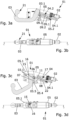
- the 1 shows an exploded drawing of a trailer hitch 01 according to the invention according to a first embodiment.
- the first embodiment of the trailer hitch 01 is characterized in that a single drive 02 is provided for transferring the coupling arm 03 between the working position and the rest position of the coupling arm 03.
- the trailer hitch 01 comprises an adjusting mechanism 04 and a housing part 05.
- the coupling arm 03 also includes a rotary bearing part 03.1, which is firmly connected to a tilting arm 06, which in turn is connected to an axle 07, which has axle projections 07.1 on both sides, wherein in the illustration of 1 only one of the axle projections 07.1 can be seen.
- the rotary bearing part 03.1 includes a bearing surface 03.2, which rotatably supports a receiving section 03.3 of the coupling head 03.
- the adjusting mechanism 04 has a threaded spindle 04.1 and a triple joint 04.2.
- the triple joint 04.2 comprises a pair of drive levers 08, which are rotatably connected via a first joint 09.1 to a head 04.3 of the threaded spindle 04.1.
- the pair of drive levers 08 is rotatably connected to a second end 10 of a locking element 11 via a second joint 09.2.
- a first end 12 of the locking element 11 includes a further joint mount 09.4, which, together with a bolt 03.4 of the pivot bearing part 03.1, forms a third joint 09.3 with the pivot bearing part 03.1 of the coupling arm 03.
- the drive 02 includes a gear 02.2 and a bearing cover 02.3 with corresponding fastening means 02.4 for fastening the drive 02 to the housing part 05.
- the drive 02 also includes a spindle nut 02.5, with which the threaded spindle 04.1 is driven.
- the housing part 05 has two side walls 05.1, which are connected to one another on a first end face 05.2 and a second end face 05.3.
- the side walls 05.1 of the housing part 05 also have link openings 05.4, which form a link 05.5.
- the link 05.5 includes a rotation section 05.8 and a translation section 05.9.
- Devices 05.6 for at least partially accommodating the drive 02 are provided on the first end face 05.2 of the housing part 05.
- anti-rotation elements 13 Arranged on the second end face 05.3 of the housing part 05 are anti-rotation elements 13 which can be brought into engagement with anti-rotation elements 14 of the coupling arm 03 of complementary design.
- the anti-rotation elements 13, 14 are designed as spherical cap combination.
- a rack 15 which, together with the pinion 16 provided on the coupling arm 03, forms a rack and pinion drive.
- a first guide means 17 is also arranged inside the housing part 05, which forms a support stop 19 for the locking element 11 at an end 18 which faces away from the drive 02.
- a second guide means 20 is also arranged, which in the perspective view of FIG 1 however, is not recognizable.
- the second guide means 22 runs essentially parallel to the first guide means 17.
- the locking element 11 further includes a stop means 11.1.
- the stop means 11.1 is designed as a pin that protrudes on both sides of the locking element 11 and limits the angle that the locking element 11 and the pair of drive levers 08 can assume in relation to one another.
- the drive levers 08 have a profile 08.1 on their edges facing the guide means 17.
- the profiling 08.1 and the stop means 11.1 are used to safely and easily reach the locking position of the locking element or to hold the coupling arm in the working position by the locking element. On the profiling 08.1 and the sling 11.1 is in the description of Figure 5i dealt with in more detail.
- the hitch of the 2 largely corresponds to the embodiment of FIG 1 . Accordingly, parts that develop a corresponding technical effect are provided with the same reference numerals as the corresponding parts of the trailer hitch according to the first embodiment 1 .
- the embodiment of 2 differs from the embodiment of 1 on the one hand by the design of the drive 02.
- the embodiment of the 2 from the embodiment of 1 in that the trailer coupling 01 has a second drive 20, which causes the coupling arm 03 to rotate about an axis of rotation A1 when the coupling arm 03 is transferred between the working position and the rest position.
- the second drive 20 sees a representation of the 2 not shown, which engages with the pinion 16 arranged on the coupling arm 03, whereby via the second drive 20, when the drive 20 is attached to the rotary bearing part 03.1 via a bracket 28, an actuation of the second drive 20 results in the Coupling arm 03 is rotated about the axis of rotation A1. Since the rotation of the coupling arm 03 is accomplished by the second drive 20, the trailer hitch 01 according to the embodiment of FIG 2 no rack 15, as in the embodiment of 1 is needed.
- the embodiments also differ in the shape of the slides 05.5 and/or the slide openings 05.4, with the function or functions of the slides 05.5 being identical.
- the links 05.5 also both have a translation section 05.9 and a rotation section 05.8.
- the different shape of the wings is due to the different drive concepts with exactly one drive 02 ( 1 ) and two drives 02, 20 ( 2 ) and due to the fact that in the embodiment of the 1 a rotation of the coupling arm 03 relative to the trailer hitch and relative to the pivot bearing part 03.1 must be effected indirectly by a translation of the pivot bearing part 03.1. Therefore falls in the embodiment 1 the translation section 05.9 of the link 05.5 is correspondingly longer than in the embodiment of FIG 2 .
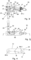
- the Figures 3a and 3b show a trailer coupling 01 with a coupling arm 03, which is in the rest position 21.
- the Figure 3a shows a section through the trailer hitch 01 along the in the Figure 3b shown level AA.
- the drive 02 has moved or pulled out the threaded spindle 04.1 as far as possible from the first end face 05.2 of the housing part 05.
- the Figures 3c and 3d show the trailer coupling 01 in an intermediate state, ie with the coupling arm 03 in an intermediate position between the rest position and the working position.
- the 3c a section through the trailer hitch 01 along the in the 3d represented level AA.
- the threaded spindle 04.1 has already been moved a little way into the interior of the housing part 05 via the drive 02.
- the angular position between the threaded spindle 04.1, the drive levers 08 and the locking element 11 are determined via the first guide means 17 and the second guide means 22.
- the details relating to the link openings 05.4 of the link 05.5 are more detailed with reference to the figure 5 described.
- the pair of figures 3e and 3f also represents a representation of the trailer coupling 01 according to the first embodiment, in which the coupling arm 03 assumes an intermediate position between the rest position and the working position.
- Figure 3e is again a section through the trailer hitch 01 along the in Fig. 3f shown level AA.
- Figures 3g and 3h show the trailer hitch 01 according to the invention in a manner of representation that is basically analogous to the preceding pairs of figures, with the coupling arm 03 in the representations of Figures 3g and 3h is about to attain the position of employment.
- the second end 10 of the locking element 11 is about to reach the end 18 of the first guide means 17 .
- the coupling arm 03 of the trailer hitch 01 has assumed the working position 23.
- the threaded spindle 04.1 was moved via the drive 02 into the interior of the housing part 05 to such an extent that the locking element 11 was tilted by the drive levers 08 in relation to the pivot bearing part 03.1 and the second end 10 of the locking element 11 now frictionally engages with an end 18 of the first Guide means 17 trained support stop 19 forms.
- the tilting of the locking element 11 was brought about by the drive lever 08, in addition to the corresponding dimensioning of the first guide means 17 and the support stop 19, so that the locking element 11 from the position shown in FIGS Figures 3a to 3h shown release position or release positions in the Figure 3i shown locking position 24 could be transferred.
- the triple joint 04.2 including the locking element 11 and the drive lever 08 is angled to the maximum.
- the anti-rotation elements 13 and 14 were also brought into engagement with one another and held in engagement with one another. This prevents the coupling arm 03 from rotating relative to the rotary bearing part 03.1 and relative to the housing part 05.
- the adhesion between the second end 10 of the locking element 11 and the support stop 19 can be formed by a comparably small force of the drive lever 08 on the second end 10 of the locking element 11 .
- the arrangement of the locking element 11 in the locking position 24 means that when a force is applied to the coupling arm 03, for example a force is applied in the direction R1, the result is that the corresponding opposing forces are transferred from the pivot bearing part 03.1 to the locking element 11 and via the support stop 19 and the first guide means 17 can be diverted into the housing part 05 of the trailer hitch 01 without force being introduced into the drive 02.
- the 4 shows a locking element 11 which, in addition to a first joint mount 09.4 and a second joint mount 09.5 at the second end 10, has an asymmetrical shape 25, in particular an asymmetrical rounding.
- the asymmetrical shape 25 is formed by an arc of a circle with the radius R, with the center point M belonging to the arc of the circle being arranged eccentrically outside the lever axis H of the locking element 11 .
- the asymmetrical rounding 25 increases the bracing force when the locking element 11 assumes the locking position 24 .
- the asymmetrical shape 25 can be used to compensate for tolerances and wear.
- the asymmetrical shape 25 also means that the locking position 24 of the locking element 11 is designed to be self-locking and can be easily reached and released again via the actuating mechanism 04.
- FIGS. 5a, 5c , 5e, 5g and 5i show sections through towbars according to the invention according to the second embodiment, as shown in the illustration in FIG 2 is shown.
- the transfer shown in the sections of the coupling arm 03 from the rest position 21 according to Figure 5a in the working position 23 according to the Figure 5i takes place largely in parallel with the corresponding processes, as they relate to the Figures 3a to 3j have been described. Accordingly, the comments on the 3 to get expelled.
- the stop means 11.1 ensures that the deflection between the locking element 11 and the drive levers 08 is limited, since when the locking position 24 of the locking element 11 is reached or shortly after, the ones opposite the profile 08.1 Edges of the drive levers 08 come to rest on the stop means 11.1, ie on the pin protruding laterally beyond the locking element 11, and thus block further rotation of the second joint 09.2.
- the stop means 11.1 and the profile 08.1 are used in the embodiment of 1 and 3 same purpose, what for example in the representation of Figure 3i is recognizable.
- the rotation of the coupling arm 03 can be decoupled from other movements during the transfer of the coupling arm 03 between the rest position and the working position and/or can be carried out independently. This allows the movements to be optimally coordinated.
- the axial projection is 07.1 in a rotating section 05.8 of the link 05.5, as shown in the illustration Figure 5b is shown. Because the approximately hook-shaped axle projection 07.1 is located in the rotating section 05.8 of the connecting link 05.5, the tilting arm 06 is rotated by rotating the axle 07 when the first drive 02 ( Figure 5a ) a force is exerted on the adjusting mechanism 04, by which the threaded spindle 04.1 is moved into the housing part 05.
- link opening 05.4 of link 05.5 is designed in such a way that rotation of axis 07 is prevented again when tilting arm 06 and thus also pivot bearing part 03.1 have assumed the position as shown, for example, in FIGS Figures 5c and 5d are shown.
- link 05.5 includes a translation section 05.9, which is designed with respect to axle projection 07.1 in such a way that when coupling arm 03 is further transferred from working position 23 to rest position 21 or vice versa, axis 07 is translated along link 05.5 and via the Tilting arm 06 accordingly also translates the pivot bearing part 03.1 and the coupling arm 03.
- the translational movements are, for example, between the representations of the Figures 5e and 5g and 5f and 5h, respectively. How to use the Fig. 5g can further see, the link is 05.5 designed such that in the working position 23 of the coupling arm 03, as for example in the Figure 5i is shown, a rotation of the axis 07 is prevented.
- the link 05.5 of the first embodiment of the trailer hitch 01 has the same shape as the link 05.5 of the second embodiment figure 5 .
- the corresponding axle projections 07.1 can also be designed slightly differently, which is the case, for example, when comparing the Figures 1 and 2 becomes evident.
Landscapes
- Engineering & Computer Science (AREA)
- Transportation (AREA)
- Mechanical Engineering (AREA)
- Arrangement And Mounting Of Devices That Control Transmission Of Motive Force (AREA)
- Agricultural Machines (AREA)
- Mechanical Operated Clutches (AREA)
Description
Die vorliegende Erfindung betrifft eine Anhängekupplung für Fahrzeuge mit einem beweglichen Kupplungsarm gemäß dem Oberbegriff des Patentanspruchs 1.The present invention relates to a trailer coupling for vehicles with a movable coupling arm according to the preamble of patent claim 1.
In der
In der
Die
Derartige motorisch verschwenkbare Anhängekupplungen sind an sich bekannt und werden eingesetzt, um Teile einer an einem Fahrzeug montierten Anhängekupplung bei Nichtgebrauch in eine gegen Sicht verdeckte Position zu bewegen, indem beispielsweise der Kupplungsarm gegenüber der Fahrzeugkarosserie oder anderen Fahrzeugteilen bewegt wird und in der Ruheposition, welche die gegen Sicht verdeckte Position darstellt, entsprechend hinter Fahrzeugteilen oder Karosserieteilen des Fahrzeugs, wie beispielsweise einem Stoßfänger oder einer Heckstoßstange, angeordnet ist.Such motor-pivoted trailer hitches are known per se and are used to move parts of a trailer hitch mounted on a vehicle into a hidden position when not in use, for example by moving the coupling arm relative to the vehicle body or other vehicle parts and in the rest position, which the represents a position concealed from view, is accordingly arranged behind vehicle parts or body parts of the vehicle, such as a bumper or a rear bumper.
Bei den Anhängekupplungen aus dem Stand der Technik ist zudem bekannt, dass in der Arbeitsstellung des Kupplungsarms, also in einer Stellung des Kupplungsarms, in der eine Ankupplung oder Verbindung mit Lasten, wie beispielsweise einem Anhänger, einem Zweiradträger oder dergleichen erfolgen kann und vorgesehen ist, der Antrieb, der zur Überführung des Kupplungsarms zwischen der Arbeitsstellung und der Ruhestellung eingesetzt wird, den Verbleib des Kupplungsarms in der Arbeitsstellung sicherstellt.In the case of trailer couplings from the prior art, it is also known that in the working position of the coupling arm, i.e. in a position of the coupling arm in which a coupling or connection to loads, such as a trailer, a bicycle carrier or the like can and is intended to take place, the drive used to move the coupling arm between the working position and the rest position ensures that the coupling arm remains in the working position.
Denn bei Kraft- oder Impulseinwirkungen auf dem Kupplungsarm, beispielsweise durch Beschleunigung, Kurvenfahrt oder Verzögern mit einem Gespann aus einem Fahrzeug und einem Anhänger, kann eine Bewegung des Kupplungsarms resultieren, sodass der Kupplungsarm lose wird und die Arbeitsstellung zumindest teilweise aufgehoben oder gelöst wird.When forces or impulses act on the coupling arm, for example due to acceleration, cornering or deceleration with a combination of a vehicle and a trailer, the coupling arm can move so that the coupling arm becomes loose and the working position is at least partially canceled or released.
Dem wird im Stand der Technik dadurch begegnet, dass der Antrieb zur Überführung zwischen der Arbeitsstellung und der Ruhestellung des Kupplungsarms in gewissen Abständen angesteuert wird, um den zumindest teilweise aus der Arbeitsstellung losgelösten oder losgeschlagenen Kupplungsarm wieder in die Arbeitsteilung zu überführen. Bei dieser wiederholten Ansteuerung des Antriebs zur Aufrechterhaltung der Arbeitsstellung des Kupplungsarms wird in der Regel von einem Nachtakten des Antriebs gesprochen.This is counteracted in the prior art in that the drive for transferring the coupling arm between the working position and the rest position is actuated at certain intervals in order to transfer the coupling arm, which has been at least partially detached or knocked loose from the working position, back into the division of labor. This repeated actuation of the drive to maintain the working position of the coupling arm is usually referred to as a re-clocking of the drive.
Diese bekannte Vorgehensweise hat jedoch den Nachteil, dass sowohl der Antrieb als auch die mit dem Antrieb verbundenen Bestandteile der Anhängekupplung einer erhöhten Beanspruchung und damit einem erhöhten Verschleiß ausgesetzt sind.However, this known procedure has the disadvantage that both the drive and the components of the trailer hitch connected to the drive are exposed to increased stress and thus increased wear.
Vor diesem Hintergrund ist es die Aufgabe der vorliegenden Erfindung, eine Anhängekupplung für Fahrzeuge mit einem beweglichen Kupplungsarm, der mit zumindest einem Antrieb zwischen einer Arbeitsstellung und einer Ruhestellung bewegbar ist, anzugeben, die die Nachteile des Stands der Technik überwindet, insbesondere ein Nachtakten des Antriebs zur Aufrechterhaltung der die Arbeitsstellung reduziert oder vollständig vermeidet.Against this background, the object of the present invention is to specify a trailer coupling for vehicles with a movable coupling arm, which can be moved between a working position and a rest position with at least one drive, which overcomes the disadvantages of the prior art, in particular re-clocking of the drive reduced or completely avoided in order to maintain the working position.
Diese Aufgabe wird bei einer Anhängekupplung der eingangs genannten Art durch die Merkmale des Patentanspruchs 1 gelöst.With a trailer hitch of the type mentioned at the outset, this object is achieved by the features of patent claim 1 .
Dadurch wird in besonders vorteilhafter Art und Weise erreicht, dass das Arretierelement einerseits die Arretierung in der Arbeitsstellung des Kupplungsarms ermöglicht und gleichzeitig die Krafteinleitung in zumindest einen Antrieb zumindest reduziert, soweit Krafteinwirkungen auf den Kupplungsarm in der Arbeitsstellung auftreten. Dadurch wird das Nachtakten des zumindest einen Antriebs zumindest deutlich reduziert, da das Arretierelement den Kupplungsarm in der Arbeitsstellung hält oder in die Arbeitsstellung beaufschlagt und gleichzeitig die Krafteinleitung in zumindest einen Antrieb zumindest reduziert und dadurch ein Lösen oder Losschlagen des Kupplungsarms, welches mit einem Nachtakten des zumindest einen Antriebs kompensiert werden müsste, verhindert. Das Arretierelement leitet gemäß der Erfindung zumindest einen Teil der über den Kupplungsarm in die Vorrichtung eingetragenen Kräfte ab und vermindert damit die Krafteinleitung auf den zumindest einen Antrieb.This is achieved in a particularly advantageous manner that the locking element on the one hand allows locking in the working position of the coupling arm and at the same time at least reduces the application of force in at least one drive, as far as forces acting on the coupling arm in the working position. This at least significantly reduces the re-clocking of the at least one drive, since the locking element holds the coupling arm in the working position or presses it into the working position and at the same time at least reduces the introduction of force into at least one drive, thereby preventing the coupling arm from being released or knocked loose, which is associated with re-clocking the at least one drive would have to be compensated, prevented. According to the invention, the locking element diverts at least part of the forces introduced into the device via the coupling arm and thus reduces the introduction of force to the at least one drive.
Gemäß einer ersten vorteilhaften Ausführungsform der Anhängekupplung kann vorgesehen sein, dass das Arretierelement den Kupplungsarm derart in der Arbeitsstellung hält, dass bei Krafteinwirkungen auf den Kupplungsarm in der Arbeitsstellung zumindest ein Antrieb kraftfrei gehalten wird. Dadurch wird ermöglicht, dass das Arretierelement die Kraftübertragung zwischen dem Kupplungsarm einerseits und dem zumindest einen Antrieb andererseits unterbricht. Außerdem hält das Arretierelement, trotz der unterbrochenen Kraftübertragung zwischen dem zumindest einen Antrieb und dem Kupplungsarm, den Kupplungsarm in der Arbeitsstellung. Dies kann beispielsweise dadurch gewährleistet werden, dass das Arretierelement die Kräfte, die bei einer Krafteinwirkung auf den Kupplungsarm entstehen und dazu geeignet sind, den Kupplungsarm aus der Arbeitsstellung zu lösen oder die Arretierung des Kupplungsarms in der Arbeitsstellung zu vermindern aufnimmt und so in die Struktur der Anhängekupplung überführt oder abgeleitet werden, dass eine Krafteinwirkung auf zumindest einen Antrieb unterbleibt. Damit wirkt das Arretierelement zusätzlich zur Sicherung der Arbeitsstellung des Kupplungsarms als "Kraftumleitung" oder "Kräftebeipass", der dafür sorgt, dass die Arretierung des Kupplungsarms in der Arbeitsstellung aufrechterhalten wird, ohne dass dazu ein Nachtakten von dem zumindest einem Antrieb nötig wird.According to a first advantageous embodiment of the trailer hitch, it can be provided that the locking element holds the coupling arm in the working position in such a way that at least one drive is kept free of force when force is applied to the coupling arm in the working position. This makes it possible for the locking element to interrupt the power transmission between the coupling arm on the one hand and the at least one drive on the other hand. In addition, the locking element keeps the coupling arm in the working position, despite the interrupted power transmission between the at least one drive and the coupling arm. This can, for example, be guaranteed that the locking element absorbs the forces that arise when a force is applied to the coupling arm and are suitable for releasing the coupling arm from the working position or for reducing the locking of the coupling arm in the working position and are thus transferred or diverted to the structure of the trailer coupling that a force is not applied to at least one drive. In addition to securing the working position of the coupling arm, the locking element also acts as a "force diversion" or "force bypass" which ensures that the coupling arm is locked in the working position without the need for reclocking of the at least one drive.
Erfindungsgemäß ist vorgesehen, dass das Arretierelement als Teil einer von einem Antrieb angetriebenen Stellmechanik ausgebildet ist. Damit wird das Arretierelement als dynamisches oder bewegliches Element der Anhängekupplung ausgestaltet. Dies bedeutet, dass das Arretierelement bei der Überführung des Kupplungsarms zwischen der Arbeitsstelle und der Ruhestellung vollständig oder als ganzes und zusammen mit anderen Bestandteilen der Stellmechanik gegenüber der Anhängekupplung bewegt wird. Das Arretierelement ist in dieser Ausführungsform nicht fest in der Anhängekupplung, insbesondere einem Gehäuseteil, angelenkt, sondern zusammen mit der Stellmechanik bewegbar.According to the invention it is provided that the locking element is designed as part of an actuating mechanism driven by a drive. The locking element is thus designed as a dynamic or movable element of the trailer hitch. This means that the locking element is moved completely or as a whole and together with other components of the actuating mechanism in relation to the trailer hitch when the coupling arm is transferred between the working position and the rest position. In this embodiment, the locking element is not fixedly articulated in the trailer hitch, in particular a housing part, but can be moved together with the actuating mechanism.
Durch die Ausbildung des Arretierelements als Teil der Stellmechanik wird die erfindungsgemäße Anhängekupplung in vorteilhafter Weise kompakter ausgeführt. Denn eine von zumindest einem Antrieb angetriebene Stellmechanik zur Überführung des Kupplungsarms zwischen der Arbeitsstellung und der Ruhestellung ist bei einer gattungsgemäßen Anhängekupplung zwangsläufig vorgesehen. Bei einer Integrierung des Arretierelements in eine solche Stellmechanik oder bei der Ausbildung des Arretierelements als Teil einer solchen Stellmechanik kann in vorteilhafter Weise ein separates Arretierelement zusätzlich zur angetriebenen Stellmechanik eingespart werden. Dadurch benötigt die erfindungsgemäße Anhängekupplung einen geringen Bauraum und könnte zudem günstiger hergestellt werden.Due to the design of the locking element as part of the adjusting mechanism, the trailer hitch according to the invention is advantageously made more compact. Because an actuating mechanism driven by at least one drive for transferring the coupling arm between the working position and the rest position is necessarily provided in a generic trailer hitch. When the locking element is integrated into such an adjusting mechanism or when the locking element is formed as part of such an adjusting mechanism, a separate locking element can advantageously be saved in addition to the driven adjusting mechanism. As a result, the trailer hitch according to the invention requires little installation space and could also be manufactured more cheaply.
Gemäß einer ebenfalls vorteilhaften Ausgestaltung kann vorgesehen sein, dass das Arretierelement in einer Freigabestellung zur Kraftübertragung zwischen zumindest einem Antrieb und dem Kupplungsarm eingerichtet ist. Eine derartige Kraftübertragung kann insbesondere dadurch erreicht werden, dass das Arretierelement als Teil einer angetriebenen Stellmechanik ausgebildet wird. Bei der Freigabestellung des Arretierelements muss es sich jedoch nicht um eine einzige Position und/oder Ausrichtung des Arretierelements gegenüber dem Kupplungsarm oder gegenüber der Anhängekupplung handeln. Vielmehr kann, insbesondere bei einer Ausbildung des Arretierelements als dynamisches Teil einer angetriebenen Stellmechanik, vorgesehen sein, dass jede Stellung des Arretierelements abseits der Stellung, die den Kupplungsarm in der Arbeitsstellung arretiert, von einer Freigabestellung des Arretierelements ausgegangen werden.According to a likewise advantageous embodiment, it can be provided that the locking element is set up in a release position for power transmission between at least one drive and the coupling arm. Such a power transmission can be achieved in particular in that the locking element is designed as part of a driven actuating mechanism. However, the release position of the locking element does not have to be a single position and/or orientation of the locking element relative to the coupling arm or relative to the trailer hitch. Rather, especially when the locking element is designed as a dynamic part of a driven actuating mechanism, it can be provided that each position of the locking element apart from the position that locks the coupling arm in the working position can be assumed to be a release position of the locking element.
Eine weitere vorteilhafte Ausführungsform der Anhängekupplung sieht vor, dass das Arretierelement zumindest eine Gelenkaufnahme aufweist. Dadurch kann unter anderem erreicht werden, dass das Arretierelement durch eine Dreh- und/oder Kippbewegung um ein entsprechendes Gelenk in die Arretierstellung überführt wird, in der das Arretierelement den Kupplungsarm in der Arbeitsstellung arretiert. Dies hat den Vorteil, dass je nach Ausbildung des Gelenks und des Arretierelements bei der Arretierung des Kupplungsarms sowie bei der Überführung des Arretierelements in eine Freigabestellung weitestgehend frei wählbare Hebel und Drehmomente zum Einsatz kommen können, so dass mit vergleichsweise geringen aufzubringenden Kräften und einem entsprechenden gewählten und durch das Arretierelement ausgebildeten Hebelarm eine sichere und stabile Arretierung des Kupplungsarms sowie umgekehrt eine leichte und sichere Erreichung der Arretierstellung und der Freigabestellung des Arretierelements erreicht wird. Gleichermaßen sicher und einfach kann dadurch die Aufhebung der Arretierung des Kupplungsarms in der Arbeitsstellung ermöglicht werden.A further advantageous embodiment of the trailer hitch provides that the locking element has at least one joint mount. As a result, it can be achieved, among other things, that the locking element is transferred into the locking position by a rotary and/or tilting movement about a corresponding joint, in which the locking element locks the coupling arm in the working position. This has the advantage that, depending on the design of the joint and the locking element, largely freely selectable levers and torques can be used when locking the coupling arm and when transferring the locking element into a release position, so that with comparatively low forces to be applied and a correspondingly selected and by the lever arm formed by the locking element, a secure and stable locking of the coupling arm and, conversely, an easy and secure achievement of the locking position and the release position of the locking element is achieved. The locking of the coupling arm in the working position can be released in an equally safe and simple manner.
In einer erfindungsgemäßen Ausgestaltung der Anhängekupplung ist vorgesehen, dass das Arretierelement an einem ersten Ende über ein Gelenk mit einem Drehlagerteil des Kupplungsarms verbunden ist. Derartige Drehlagerteile kommen bei gattungsgemäßen Anhängekupplungen zum Einsatz, um eine Überlagerung verschiedener Bewegungen des Kupplungsarms bei der Überführung zwischen der Ruhestellung und der Arbeitsstellung erreichen zu können. Insbesondere ermöglichen solche Drehlagerteile zumindest auch die Rotation des Kupplungsarms um eine Rotationsachse. Der Kupplungsarm kann dazu einen Aufnahmeabschnitt aufweisen, der an einer Lagerfläche des Drehlagerteils drehbar gelagert ist. Die Verbindung des Arretierelements an einem ersten Ende mit einem entsprechenden Drehlagerteil über ein Gelenk sorgt in vorteilhafter Weise für eine sichere Arretierung des Kupplungsarms in der Arbeitsstellung. Gleichzeitig ermöglicht eine derartige Verbindung zwischen Drehlagerteil und Arretierelement die Einbindung des Arretierelements in eine Stellmechanik. Die Verbindung kann beispielsweise über die oben bereits beschriebene Gelenkaufnahme des Arretierelements einerseits und einem vom Drehlagerteil ausgebildeten Gelenk andererseits, beispielsweise in Form eines Gelenkbolzens, erreicht werden.In an embodiment of the trailer coupling according to the invention, it is provided that the locking element is connected at a first end via a joint to a pivot bearing part of the coupling arm. Such rotary bearing parts are used in trailer hitches of this type in order to be able to superimpose different movements of the coupling arm when transferring between the rest position and the working position. In particular, such rotary bearing parts at least also allow the coupling arm to rotate about an axis of rotation. For this purpose, the coupling arm can have a receiving section which is rotatably mounted on a bearing surface of the rotary bearing part. The connection of the locking element at a first end to a corresponding pivot bearing part via a joint advantageously ensures that the coupling arm is securely locked in the working position. At the same time, such a connection between the pivot bearing part and the locking element enables the locking element to be integrated into an actuating mechanism. The connection can be achieved, for example, via the above-described joint receptacle of the locking element on the one hand and a joint formed by the pivot bearing part on the other hand, for example in the form of a joint bolt.
Wie oben bereits angedeutet, kann über die Nutzung entsprechender Hebelmomente eine einfache und sichere Überführung des Arretierelements zwischen einer Arretierstellung und einer Freigabestellung bewerkstelligt werden. Dementsprechend sieht eine erfindungsgemäße Ausgestaltung der Anhängekupplung vor, dass das Arretierelement über eine Drehung gegenüber dem Drehlagerteil zwischen einer Arretierstellung und einer Freigabestellung bewegbar ist.As already indicated above, a simple and safe transfer of the locking element between a locking position and a release position can be accomplished by using corresponding lever moments. Accordingly, an embodiment of the trailer hitch according to the invention provides that the locking element can be moved between a locking position and a release position by rotating it relative to the rotary bearing part.
Zudem ist erfindungsgemäß vorgesehen, dass das Arretierelement in der Arretierstellung an einem Stützanschlag zur Anlage kommt. Besonders vorteilhaft ist, wenn das Arretierelement mit einem zweiten Ende des Arretierelements an einem Stützanschlag zu Anlage kommt. Da sich die Arretierstellung des Arretierelements auch dadurch auszeichnet, dass in der Arretierstellung des Arretierelements der Kupplungsarm in der Arbeitsstellung gehalten wird, kann die vorteilhafte Ausführungsform auch so verstanden werden, dass das Arretierelement so ausgestaltet ist, dass es, insbesondere mit einem zweiten Ende an einem Stützanschlag zur Anlage kommt, wenn das Arretierelement den Kupplungsarm in der Arbeitsstellung hält.In addition, it is provided according to the invention that the locking element comes into contact with a support stop in the locking position. It is particularly advantageous if the locking element comes to rest against a support stop with a second end of the locking element. Since the If the locking position of the locking element is also characterized in that the coupling arm is held in the working position in the locking position of the locking element, the advantageous embodiment can also be understood in such a way that the locking element is designed in such a way that it, in particular with a second end, rests against a support stop comes when the locking element holds the coupling arm in the working position.
Dabei kann beispielsweise vorgesehen sein, dass der Stützanschlag in einem Gehäuseteil der Anhängekupplung ausgebildet ist und so mit dem Gehäuseteil verbunden ist, dass in der Arretierstellung des Arretierelements eine Krafteinleitung auf den Kupplungsarm über das Arretierelement und den Stützanschlag in das Gehäuseteil der Anhängekupplung abgeleitet wird, wobei der zumindest eine Antrieb zumindest entlastet oder vollständig kraftfrei gehalten wird. In der Arretierstellung kann zwischen dem Stützanschlag und dem Arretierelement ein Kraftschluss oder Reibschluss vorliegen. Dabei ist vorteilhaft vorgesehen, dass das Arretierelement, insbesondere das zweite Ende des Arretierelements, und der Stützschlag so ausgestaltet sind und in der Arretierstellung so zueinander ausgerichtet sind, dass eine Krafteinwirkung auf den Kupplungsarm den Kraftschluss zwischen Stützanschlag und Arretierelement erhöht oder zumindest unverändert lässt. Dadurch wird eine Selbsthemmung des Arretierelements erreicht, die dafür sorgt, dass das Arretierelement, insbesondere bei Krafteinwirkungen auf den Kupplungsarm in der Arbeitsstellung des Kupplungsarms, die Arretierstellung nicht verlässt, sondern vielmehr weiter in die Arretierstellung beaufschlagt wird.Provision can be made, for example, for the support stop to be formed in a housing part of the trailer coupling and to be connected to the housing part in such a way that when the locking element is in the locking position, a force is applied to the coupling arm via the locking element and the support stop into the housing part of the trailer coupling, wherein the at least one drive is at least relieved or kept completely free of force. In the locking position, there can be a force fit or friction fit between the support stop and the locking element. It is advantageously provided that the locking element, in particular the second end of the locking element, and the support stop are designed and aligned with one another in the locking position such that a force acting on the coupling arm increases the frictional connection between the support stop and the locking element or at least leaves it unchanged. This achieves self-locking of the locking element, which ensures that the locking element does not leave the locking position, in particular when force is applied to the coupling arm in the working position of the coupling arm, but rather is further urged into the locking position.
Besonders vorteilhaft kann zudem vorgesehen sein, dass das Arretierelement an einem zweiten Ende eine asymmetrische Form, insbesondere eine asymmetrische Abrundung, aufweist. Die asymmetrische Form kann beispielsweise durch eine gegenüber einer Längssymmetrieachse des Arretierelements exzentrisch angeordnete Kreis-Abrundung ausgeführt sein. Dadurch kann erreicht werden, dass die Verspannkraft zwischen Arretierelement und einem Stützanschlag in der Arretierstellung des Arretierelements vergrößert und darüber hinaus ein Ausgleich für Verschleiß und Toleranzen gebildet wird. Soweit nicht das zweite Ende, sondern ein anderer Teil des Arretierelements mit einem Stützanschlag oder einem gleichwirkenden Vorrichtungsteil zur Anlage kommt, kann auch derjenige Teil des Arretierelements die asymmetrische Form, insbesondere die asymmetrische Abrundung, aufweisen.Provision can also be made particularly advantageously for the locking element to have an asymmetrical shape, in particular an asymmetrical rounding, at a second end. The asymmetrical shape can be implemented, for example, by a circular rounding which is arranged eccentrically with respect to a longitudinal axis of symmetry of the locking element. In this way it can be achieved that the bracing force between the locking element and a support stop in the locking position of the locking element is increased and, in addition, a compensation for wear and tolerances is formed. If it is not the second end but another part of the locking element that comes into contact with a support stop or a device part with the same effect, that part of the locking element can also have the asymmetrical shape, in particular the asymmetrical rounding.
In einer weiteren, besonders vorteilhaften Ausgestaltung der Anhängekupplung kann vorgesehen sein, dass die Anhängekupplung zumindest ein Führungsmittel zur Führung des Arretierelements, insbesondere des zweiten Endes des Arretierelements, in der Freigabestellung des Arretierelements oder außerhalb der Arretierstellung des Arretierelements umfasst. Durch das zumindest eine Führungsmittel kann sichergestellt werden, dass das Arretierelement in der Freigabestellung bei der Überführung zwischen der Ruhestellung und der Arbeitsstellung geführt wird, was bedeutet, dass ungewollte Bewegungen des Arretierelements, wie beispielsweise ein ungewolltes Verdrehen, Verkippen oder Querstellen des Arretierelements in der Freigabestellung verhindert wird.In a further, particularly advantageous embodiment of the trailer hitch, it can be provided that the trailer hitch comprises at least one guide means for guiding the locking element, in particular the second end of the locking element, in the release position of the locking element or outside of the locking position of the locking element. The at least one guide means can ensure that the locking element is guided in the release position during the transfer between the rest position and the working position, which means that unwanted movements of the locking element, such as unwanted twisting, tilting or transverse positioning of the locking element in the release position is prevented.
Besonders vorteilhaft kann vorgesehen sein, dass ein Ende des zumindest einen Führungsmittels einen Stützanschlag ausbildet, in dem das Arretierelement in der Arretierstellung zur Anlage kommt. Zumindest ein Führungselement zur Führung des Arretierelements ist insbesondere dann besonders vorteilhaft, wenn das Arretierelement gleichzeitig Teil einer Stellmechanik ist und/oder in der Freigabestellung zur Kraftübertragung zwischen zumindest einem Antrieb und dem Kupplungsarm eingerichtet ist.Provision can be made particularly advantageously for one end of the at least one guide means to form a support stop, in which the locking element comes to rest in the locking position. At least one guide element for guiding the locking element is particularly advantageous when the locking element is also part of an actuating mechanism and/or is set up in the release position for power transmission between at least one drive and the coupling arm.
Weiterhin kann besonders vorteilhaft vorgesehen werden, dass das Arretierelement als ein Arm eines Dreifachgelenks ausgebildet ist. Das Vorsehen eines Dreifachgelenks oder eines Gelenkarms mit drei Gelenken unter Einbeziehung des Arretierelements bringt den Vorteil mit sich, dass das Arretierelement einerseits als Teil der Stellmechanik ausgebildet sein kann und dass darüber hinaus weitere Arme des Dreifachgelenks einerseits ebenfalls als Teil der Stellmechanik ausgebildet sein können und andererseits als Antriebshebel für das Arretierelement dienen können, um das Arretierelement nicht nur, aber auch zwischen der Freigabestellung und der Arretierstellung zu bewegen, insbesondere zu verdrehen. Der entsprechende Gelenkarm oder das Dreifachgelenk kann also zwei Arme und drei Gelenke umfassen, wobei zumindest ein Arm durch das Arretierelement gebildet wird. Bevorzugt wird der zweite Arm von zumindest einem Antriebshebel gebildet.Furthermore, it can be provided particularly advantageously that the locking element is designed as an arm of a triple joint. The provision of a triple joint or an articulated arm with three joints including the locking element has the advantage that the locking element can be designed as part of the adjusting mechanism and that other arms of the triple joint can also be designed as part of the adjusting mechanism on the one hand and on the other hand can serve as a drive lever for the locking element in order to move the locking element not only, but also between the release position and the locking position, in particular to twist it. The corresponding articulated arm or the triple joint can therefore comprise two arms and three joints, with at least one arm being formed by the locking element. The second arm is preferably formed by at least one drive lever.
Besonders vorteilhaft kann in diesem Zusammenhang vorgesehen sein, dass das Dreifachgelenk derart ausgestaltet ist, dass es in der Ruhestellung des Kupplungsarms eine maximale Streckung erfährt, wobei eine vollständige Streckung verhindert wird. Dies bedeutet, dass das Arretierelement und der zumindest eine Antriebshebel in jeder Position einen Winkel einschließen, der nicht gleich 180° ist. Dadurch wird in einer besonders vorteilhaften Art und Weise verhindert, dass das Dreifachgelenk bei der Überführung des Kupplungsarms zwischen der Arbeitsstellung und der Ruhestellung in eine Totpunktposition überführt wird.In this context, it can be particularly advantageous for the triple joint to be designed in such a way that it experiences maximum stretching when the coupling arm is in the rest position, with complete stretching being prevented. This means that the locking element and the at least one drive lever enclose an angle that is not equal to 180° in every position. This prevents, in a particularly advantageous manner, that the triple joint is transferred into a dead center position when the coupling arm is transferred between the working position and the rest position.
Ebenfalls kann vorteilhaft vorgesehen sein, dass das Dreifachgelenk derart ausgebildet ist, dass es in der Arbeitsstellung des Kupplungsarms eine maximale Abwinklung erfährt. Dies sorgt besonders vorteilhaft für eine einfache und sichere Herstellung der Arretierstellung des Arretierelements und gleichermaßen für eine sichere und einfache Überführung des Arretierelements zwischen der Arretierstellung und der Freigabestellung.It can also advantageously be provided that the triple joint is designed in such a way that it undergoes a maximum deflection in the working position of the coupling arm. In a particularly advantageous manner, this ensures that the locking position of the locking element can be established easily and securely, and likewise that the locking element can be transferred securely and easily between the locking position and the release position.
Eine weitere, besonders bevorzugte Ausführungsform der Anhängekupplung sieht zumindest zwei Führungsmittel vor, welche bei der Überführung des Kupplungsarms zwischen Ruhestellung und Arbeitsstellung die Relativlage der Arme des Dreifachgelenks zueinander bestimmen oder begrenzen. Dazu können die Führungsmittel je eine Führungsfläche oder Führungsoberfläche ausbilden. Die Führungsflächen können einander zugewandt sein, so dass zwischen den Führungsflächen ein Führungskanal ausgebildet wird. An den Führungsflächen können das Arretierelement und/oder weitere Teile der Stellmechanik oder des Dreifachgelenks zur Anlage kommen und bei der Überführung des Kupplungsarms zwischen Ruhestellung und Arbeitsstellung entlanggleiten. Dadurch wird eine präzise und wiederholbare Bewegung zumindest des Arretierelements sichergestellt.A further, particularly preferred embodiment of the trailer coupling provides at least two guide means which determine or limit the relative position of the arms of the triple joint to one another when the coupling arm is transferred between the rest position and the working position. For this purpose, the guide means can each form a guide face or guide surface. The guide surfaces can face each other so that a guide channel is formed between the guide surfaces. The locking element and/or other parts of the adjusting mechanism or the triple joint can come to rest on the guide surfaces and slide along during the transfer of the coupling arm between the rest position and the working position. This ensures precise and repeatable movement of at least the locking element.
Gemäß einer weiteren, besonders vorteilhaften Ausführungsform der Anhängekupplung kann vorgesehen sein, dass ein Drehlagerteil des Kupplungsarms starr mit einem Kipparm verbunden ist. Dadurch wird vorteilhaft ermöglicht, dass das Drehlagerteil und damit auch der Kupplungsarm eine Kippbewegung ausführen kann, die mit anderen Bewegungen bei der Überführung des Kupplungsarms zwischen der Arbeitsstellung und der Ruhestellung überlagert werden kann.According to a further, particularly advantageous embodiment of the trailer coupling, it can be provided that a rotary bearing part of the coupling arm is rigidly connected to a tilting arm. This advantageously enables the pivot bearing part and thus also the coupling arm to be able to perform a tilting movement, which can be superimposed with other movements during the transfer of the coupling arm between the working position and the rest position.
In diesem Zusammenhang kann besonders vorteilhaft vorgesehen sein, dass der Kipparm an einem vom Drehlagerteil angewandten Ende starr mit einer Achse verbunden ist, die insbesondere über zumindest einen Achsvorsprung, in einer Kulisse geführt wird. Dies bedeutet, dass der Achsvorsprung als Kulissenstein dient, der dafür sorgt, dass die Achse in der oder durch die Kulisse geführt wird. Durch die Ausbildung einer Achse an dem von dem Drehlagerteil abgewandten Ende des Kipparms sowie durch die Führung der Achse in eine Kulisse, insbesondere über zumindest einen Achsvorsprung oder Kulissenstein, kann in besonders vorteilhafter Weise das Ausführen oder der Zeitpunkt für das Ausführen einer Kippbewegung des Drehlagerteils um eine Kippachse gesteuert werden.In this context, it can be particularly advantageous for the tilting arm to be rigidly connected at an end facing away from the rotary bearing part to an axle which is guided in a connecting link, in particular via at least one axle projection. This means that the axle projection serves as a sliding block that ensures that the axle is guided in or through the link. By forming an axis on the end of the tilting arm facing away from the pivot bearing part and by guiding the axis in a link, in particular via at least one axis projection or sliding block, the execution or the point in time for the execution of a tilting movement of the pivot bearing part can be changed in a particularly advantageous manner a tilting axis can be controlled.
Dazu kann beispielsweise vorgesehen sein, dass die Kulisse und der zumindest eine Achsvorsprung so zueinander ausgeführt sind, dass in einem gewissen Teil oder Abschnitt der Kulisse die mit dem Kipparm verbundene Achse freigegeben und damit zumindest um einen gewissen Winkel drehbar ist, wohingegen die Kulisse und der zumindest eine Achsvorsprung in anderen Abschnitten der Kulisse so zueinander abgestimmt sind, dass die Rotation der Achse verhindert wird. Dadurch kann die Verkippung des Drehlagerteils um den Kipparm in besonders vorteilhafter Weise ohne einen eigenen oder zusätzlichen Antrieb erfolgen, sondern als Resultat einer sonstigen von dem zumindest einen Antrieb bewirkten Bewegung des Kupplungsarms und insbesondere des Drehlagerteils des Kupplungsarms realisiert werden.For this purpose, it can be provided, for example, that the link and the at least one axis projection are designed in relation to one another such that in a certain part or section of the link, the axis connected to the tilting arm is released and can therefore be rotated at least by a certain angle, whereas the link and the at least one axle projection in other sections of the connecting link are matched to one another in such a way that the rotation of the axle is prevented. As a result, the pivot bearing part can be tilted about the tilting arm in a particularly advantageous manner without its own or an additional drive, but rather as a result of another movement of the coupling arm and in particular the pivot bearing part of the coupling arm caused by the at least one drive.
Demnach kann besonders bevorzugt vorgesehen sein, dass die Kulisse und insbesondere der Achsvorsprung derart ausgestaltet ist oder ausgestaltet sind, dass in der Arbeitsstellung des Kupplungsarms, insbesondere in der Arretierstellung des Arretierelements, eine Rotation der mit dem Kipparm verbundenen Achse verhindert wird. Dadurch wird auch sichergestellt, dass bei einer Krafteinwirkung auf den Kupplungsarm in der Arbeitsstellung des Kupplungsarms eine effektive Verringerung oder Verhinderung einer Krafteinleitung auf zumindest einen Antrieb der Anhängekupplung erfolgen kann.Accordingly, it can particularly preferably be provided that the connecting link and in particular the axle projection is designed or are designed in such a way that in the working position of the coupling arm, in particular in the locking position of the locking element, rotation of the axis connected to the tilting arm is prevented. This also ensures that when a force is applied to the coupling arm in the working position of the coupling arm, an effective reduction or prevention of the application of force to at least one drive of the trailer hitch can take place.
Gemäß einer weiteren, besonders bevorzugten Ausführungsform der Anhängekupplung kann vorgesehen sein, dass die Kulisse einen Translationsabschnitt aufweist, der, insbesondere bezogen auf einen Achsvorsprung der Achse, derart ausgestaltet ist, dass bei der Überführung des Kupplungsarms aus der Arbeitsstellung und die Ruhestellung zunächst eine Verschiebung oder Translation der Achse entlang der Kulisse erfolgt. Dadurch kann auch erreicht werden, dass bei der Überführung des Kupplungsarms aus der Arbeitsstellung in die Ruhestellung zunächst eine Translation des Kupplungsarms herbeigeführt wird, die ggf. mit einer Rotation des Kupplungsarms überlagert werden kann.According to a further, particularly preferred embodiment of the trailer hitch, it can be provided that the connecting link has a translation section which, in particular in relation to an axial projection of the axle, is designed in such a way that when the coupling arm is transferred from the working position to the rest position, a displacement or Translation of the axis takes place along the backdrop. In this way it can also be achieved that during the transfer of the coupling arm from the working position to the rest position, first a translation of the coupling arm is brought about, which can possibly be superimposed with a rotation of the coupling arm.
Gemäß einer weiteren, bevorzugten Ausführungsform der Anhängekupplung kann vorgesehen sein, dass die Kulisse einen Rotationsabschnitt aufweist, der, insbesondere unter Berücksichtigung des zumindest einen Achsenvorsprungs, derart ausgestaltet ist, dass bei der Überführung des Kupplungsarms aus der Arbeitsstellung in die Ruhestellung zum Erreichen der Ruhestellung eine Rotation der Achse erfolgt. Dabei kann vorteilhaft vorgesehen sein, dass die Rotation der Achse im Rotationsabschnitt der Kulisse zu einer Verkippung des Kipparms und damit zu einer entsprechenden Verkippung des Drehlagerteils des Kupplungsarms und des Kupplungsarms führt. Eine derartige Bewegung zur Erreichung der Ruhestellung des Kupplungsarms hat den Vorteil, dass der Kupplungsarm in der Ruhestellung besonders platzsparend angeordnet werden kann und zudem besonders einfach in eine gegen Sicht verdeckte Position am Fahrzeug angeordnet werden kann.According to a further preferred embodiment of the trailer hitch, it can be provided that the connecting link has a rotating section which, in particular taking into account the at least one axial projection, is designed in such a way that when the coupling arm is transferred from the working position to the rest position in order to reach the rest position, a rotation of the axis takes place. It can advantageously be provided that the rotation of the axis in the rotating section of the gate leads to a tilting of the tilting arm and thus to a corresponding tilting of the pivot bearing part of the coupling arm and the coupling arm. Such a movement to reach the rest position of the coupling arm has the advantage that the coupling arm can be arranged in a particularly space-saving manner in the rest position and can also be arranged particularly easily in a hidden position on the vehicle.
Die vorangehend beschriebenen Ausgestaltungen der Kulisse und/oder des Achsenvorsprungs dienen gleichermaßen umgekehrt auch zur Überführung des Kupplungsarms aus der Ruhestellung in die Arbeitsstellung. Dabei kann zunächst eine Rotation oder Verkippung über den Rotationsabschnitt erfolgen, gefolgt von einer Translation entlang des Translationsabschnitts, wobei die Kulisse zudem so ausgeführt sein kann, dass in der Position, in der die Arbeitsstellung des Kupplungsarms erreicht wird, eine Rotation der Achse verhindert wird.Conversely, the configurations of the link and/or the axle projection described above also serve to transfer the coupling arm from the rest position to the working position. In this case, a rotation or tilting can first take place via the rotation section, followed by a translation along the translation section, in which case the connecting link can also be designed in such a way that rotation of the axis is prevented in the position in which the working position of the coupling arm is reached.
Eine weitere, besonders bevorzugte Ausführungsform der Anhängekupplung sieht vor, dass die Anhängekupplung ein Gehäuseteil aufweist, welches zumindest zur Aufnahme des Arretierelements dient. Weiter vorteilhaft kann vorgesehen sein, dass das Gehäuseteil die Stellmechanik und/oder das Drehlagerteil sowie ggf. Teile des Kupplungsarms aufnimmt. Dadurch können die entsprechenden Teile der Anhängekupplung besonders effektiv vor schädlichen Umwelteinflüssen geschützt werden.A further, particularly preferred embodiment of the trailer hitch provides that the trailer hitch has a housing part which serves at least to accommodate the locking element. Further advantageous can be provided that the housing part accommodates the adjusting mechanism and/or the pivot bearing part and, if necessary, parts of the coupling arm. As a result, the corresponding parts of the trailer hitch can be protected particularly effectively against harmful environmental influences.
Eine weitere, besonders vorteilhafte Ausgestaltung sieht vor, dass das Gehäuseteil zwei Seitenwände umfasst, in denen Kulissenöffnungen einer Kulisse angeordnet sind. Damit wird erreicht, dass die Seitenwände neben anderen Funktionen auch eine Funktion bei der Führung der Elemente der Anhängekupplung bei der Überführung des Kupplungsarms zwischen Ruhestellung und Arbeitsstellung ausüben.A further, particularly advantageous embodiment provides that the housing part comprises two side walls in which link openings of a link are arranged. This ensures that the side walls, in addition to other functions, also have a function in guiding the elements of the trailer coupling when the coupling arm is transferred between the rest position and the working position.
Eine weitere, besonders vorteilhafthafte Ausgestaltung der Anhängekupplung sieht vor, dass das Gehäuseteil, insbesondere an einer ersten Stirnseite des Gehäuseteils, Einrichtungen zur zumindest teilweisen Aufnahme von zumindest einem Antrieb aufweisen. Dadurch kann gewährleistet werden, dass die mitunter empfindlichen Bestandteile des zumindest einen Antriebs gegenüber Umwelteinwirkungen geschützt werden. Außerdem kann dadurch eine sichere Anordnung des Antriebs gewährleistet werden. Weiter lässt sich dadurch eine kompakte Bauweise der Anhängekupplung erreichen.A further, particularly advantageous embodiment of the trailer hitch provides that the housing part, in particular on a first end face of the housing part, has devices for at least partially accommodating at least one drive. This can ensure that the sometimes sensitive components of the at least one drive are protected against environmental influences. In addition, a safe arrangement of the drive can thereby be ensured. A compact design of the trailer hitch can also be achieved as a result.
In einer weiteren, besonders bevorzugten Ausgestaltung der Anhängekupplung kann vorgesehen sein, dass der Kupplungsarm Drehsicherungselemente aufweist, die mit komplementären Drehsicherungselementen in Eingriff bringbar sind und in der Arbeitsstellung des Kupplungsarms eine Rotation des Kupplungsarms verhindern. Die Drehsicherungselemente sind dabei so ausgestaltet, dass deren gegenseitiger Eingriff gerade dann vorliegt oder erreicht wird, wenn der Kupplungsarm in der Arbeitsstellung befindlich ist. Die Erreichung der Arbeitsstellung des Kupplungsarms führt also gleichzeitig zum Ineinandergreifen oder in Eingriff bringen der komplementären Drehsicherungselemente. Um die Rotation des Kupplungsarms in der Arbeitsstellung zu verhindern, kann vorteilhaft vorgesehen sein, dass die zu den Drehsicherungselementen des Kupplungsarms komplementären Drehsicherungselemente an einem Gehäuseteil der Anhängekupplung ortsfest und unbeweglich angeordnet sind.In a further, particularly preferred embodiment of the trailer coupling, it can be provided that the coupling arm has anti-rotation elements which can be brought into engagement with complementary anti-rotation elements and prevent rotation of the coupling arm in the working position of the coupling arm. The anti-rotation elements are designed in such a way that their mutual engagement is present or is achieved when the coupling arm is in the working position. The achievement of the working position of the coupling arm thus leads at the same time to the meshing or bringing into engagement of the complementary anti-rotation elements. In order to prevent the rotation of the coupling arm in the working position, it can advantageously be provided that the anti-rotation elements complementary to the anti-rotation elements of the coupling arm are arranged in a stationary and immovable manner on a housing part of the trailer hitch.
Beispielsweise kann vorgesehen sein, dass an einer zweiten Stirnseite des Gehäuseteils Drehsicherungselemente angeordnet sind, die mit komplementären Drehsicherungselementen des Kupplungsarms in Eingriff bringbar sind und in der Arbeitsstellung des Kupplungsarms eine Rotation des Kupplungsarms gegenüber dem Gehäuseteil verhindern. In einer alternativen Ausgestaltungsform kann auch vorgesehen sein, dass die Drehsicherungselemente einerseits an dem Kupplungsarm vorgesehen und die entsprechend komplementären Drehsicherungselemente an einer anderen Position der Anhängekupplung angeordnet sind, so dass sie in der Arbeitsstellung des Kupplungsarms mit den Drehsicherungselementen des Kupplungsarms in Eingriff bringbar sind und eine Rotation des Kupplungsarms verhindern.For example, it can be provided that anti-rotation elements are arranged on a second end face of the housing part, which can be brought into engagement with complementary anti-rotation elements of the coupling arm and prevent rotation of the coupling arm relative to the housing part in the working position of the coupling arm. In an alternative embodiment, it can also be provided that the anti-rotation elements are provided on the one hand on the coupling arm and the corresponding complementary anti-rotation elements are arranged at another position of the trailer hitch, so that they can be brought into engagement with the anti-rotation elements of the coupling arm in the working position of the coupling arm and Prevent rotation of the clutch arm.
Das Arretierelement kann dabei so ausgestaltet sein, dass es in seiner Arretierstellung, also in der Arbeitsstellung des Kupplungsarms, die komplementären Drehsicherungselemente miteinander in Eingriff hält. Außerdem kann vorgesehen sein, dass das Arretierelement derart ausgestaltet ist, dass es beim Übergang in seine Freigabestellung den Eingriff der komplementären Drehsicherungselemente auflöst, aufhebt oder zumindest nicht weiter befördert.The locking element can be designed in such a way that in its locking position, that is to say in the working position of the coupling arm, it holds the complementary anti-rotation elements in engagement with one another. In addition, it can be provided that the locking element is designed in such a way that it dissolves or cancels the engagement of the complementary anti-rotation elements during the transition to its release position, or at least does not promote it any further.
Eine weitere, besonders vorteilhafte Ausgestaltung der Anhängekupplung sieht vor, dass die Anhängekupplung genau einen Antrieb zur Überführung des Kupplungsarms zwischen der Arbeitsstellung und der Ruhestellung aufweist. Dies bedeutet, dass die Anhängekupplung genau einen Antrieb aufweist und dass die verschiedenen Bewegungen oder Teilbewegungen des Kupplungsarms bei der Überführung zwischen Arbeitsstelle und Ruhestellung allesamt zumindest mittelbar auf den genau einen Antrieb zurückgehen. Dabei kann beispielsweise vorgesehen sein, dass der zumindest eine Antrieb als Linearantrieb ausgestaltet ist und demnach primär oder unmittelbar eine Translationsbewegung verursacht, wobei alle Bewegungen des Kupplungsarms und auch die sonstigen Bewegungen der Teile der Anhängekupplung bei der Überführung des Kupplungsarms zwischen Arbeitsstellung und Ruhestellung mittelbar auf die Translationsbewegung des Linearantriebs zurückgehen. Eine Ausführung der Anhängekupplung mit genau einem Antrieb hat den Vorteil, dass die Anhängekupplung dadurch kompakter und kostengünstiger hergestellt werden kann.A further, particularly advantageous embodiment of the trailer coupling provides that the trailer coupling has exactly one drive for transferring the coupling arm between the working position and the rest position. This means that the trailer hitch has exactly one drive and that the various movements or partial movements of the coupling arm when transferring between work and rest position all go back at least indirectly to exactly one drive. It can be provided, for example, that the at least one drive is designed as a linear drive and therefore primarily or directly causes a translational movement, with all movements of the coupling arm and also the other movements of the parts of the trailer hitch when the coupling arm is transferred between the working position and the rest position indirectly on the Go back translational movement of the linear drive. An embodiment of the trailer hitch with exactly one drive has the advantage that the trailer hitch can be made more compact and cheaper.
Besonders vorteilhaft kann dabei vorgesehen sein, dass der eine Antrieb bei der Überführung des Kupplungsarms zwischen der Arbeitsstellung und der Ruhestellung eine Translation und eine Drehung des Drehlagerteils sowie eine Rotation des Kupplungsarms bewirkt. Wie bereits erwähnt, können die Bewegungen auch mittelbar von dem Antrieb bewirkt werden. Dabei können die einzelnen Bewegungen zum Teil miteinander überlagert werden, so dass in bestimmten Abschnitten der Überführung des Kupplungsarms zwischen Ruhestellung und Arbeitsstellung mehrere Bewegungen gleichzeitig ausgeführt werden.Provision can be made particularly advantageously for one drive to cause translation and rotation of the rotary bearing part and rotation of the coupling arm when the coupling arm is transferred between the working position and the rest position. As already mentioned, the movements can also be effected indirectly by the drive. The individual movements can be partially superimposed with one another, so that in certain sections of the transfer of the coupling arm between the rest position and the working position, several movements are carried out simultaneously.
Gemäß einer weiteren, besonders bevorzugten Ausgestaltung der Anhängekupplung kann vorgesehen sein, dass die Anhängekupplung einen Zahnstange-Ritzel-Trieb aufweist, wobei die Zahnstange und das Ritzel derart angeordnet sind, dass bei der Überführung des Kupplungsarms zwischen der Arbeitsstellung und der Ruhestellung eine Translation des Drehlagerteils zum abschnittsweisen Eingriff zwischen Zahnstange und Ritzel führt und eine Rotation des Kupplungsarms bewirkt. Alternativ zu Zahnstange und Ritzel können auch andere Kombinationen unter Ausbildung eines entsprechenden Triebs verwendet werden. Beispielsweise könnten auch eine Reibstange und ein Reibrad zum Einsatz kommen.According to a further, particularly preferred embodiment of the trailer coupling, it can be provided that the trailer coupling has a rack and pinion drive, with the rack and pinion being arranged in such a way that when the coupling arm is transferred between the working position and the rest position, the pivot bearing part is translated results in intermittent rack and pinion engagement and rotation of the clutch arm. As an alternative to rack and pinion, other combinations can also be used to form a corresponding drive. For example, a friction rod and a friction wheel could also be used.
Um den abschnittsweisen Eingriff und die während des Eingriffs stattfindende Rotation des Kupplungsarms zu ermöglichen, kann beispielsweise vorgesehen sein, dass die Zahnstange an dem Gehäuseteil, bevorzugt an einer Innenseite einer Seitenwand des Gehäuseteils, und das Ritzel an dem Kupplungsarm, insbesondere an einem von einem Kupplungskopf abgewandten Ende, derart angeordnet ist, dass bei der Überführung des Kupplungsarms zwischen der Arbeitsstellung und der Ruhestellung über eine Translation des Drehlagerteils zumindest abschnittsweise ein Eingriff zwischen der Zahnstange und dem Ritzel herbeigeführt wird, und zu einer Rotation des Kupplungsarms führt. Besonders bevorzugt kann dabei vorgesehen sein, dass das Ritzel als Stirnradsegment ausgeführt ist, welches an dem Kupplungsarm angeordnet und/oder mit dem Kupplungsarm verbunden ist.To the sectional intervention and during to enable the rotation of the coupling arm that takes place during the engagement, it can be provided, for example, that the toothed rack is arranged on the housing part, preferably on an inner side of a side wall of the housing part, and the pinion is arranged on the coupling arm, in particular on an end remote from a coupling head, in such a way that that during the transfer of the coupling arm between the working position and the rest position via a translation of the rotary bearing part, an engagement between the toothed rack and the pinion is brought about at least in sections, and leads to a rotation of the coupling arm. Provision can particularly preferably be made for the pinion to be designed as a spur gear segment which is arranged on the coupling arm and/or is connected to the coupling arm.
Eine weitere, vorteilhafte Ausgestaltung der Anhängekupplung sieht vor, dass bei der Überführung des Kupplungsarms zwischen der Arbeitsstellung und der Ruhestellung ein erster Antrieb eine Translation und eine Verkippung des Drehlagerteils des Kupplungsarms und ein zumindest zweiter Antrieb eine Rotation des Kupplungsarms bewirkt. Eine Ausgestaltung der Anhängekupplung mit zumindest zwei Antrieben hat den Vorteil, dass die jeweiligen Bewegungen oder Teilbewegungen des Kupplungsarms entkoppelt und dementsprechend voneinander unabhängig oder zumindest teilweise voneinander unabhängig ausgeführt werden können.Another advantageous embodiment of the trailer coupling provides that when the coupling arm is transferred between the working position and the rest position, a first drive causes a translation and a tilting of the pivot bearing part of the coupling arm and at least a second drive causes a rotation of the coupling arm. An embodiment of the trailer coupling with at least two drives has the advantage that the respective movements or partial movements of the coupling arm are decoupled and can accordingly be carried out independently or at least partially independently of one another.
Weitere Vorteile und Einzelheiten der erfindungsgemäßen Anhängekupplung werden nachfolgend unter Zuhilfenahme der beigefügten, schematisierten Zeichnungen erläutert werden, welche Ausführungsbeispiele der Anhängekupplung zeigen. Im Einzelnen zeigen die Figuren:
- Fig. 1
- eine Explosionszeichnung einer erfindungsgemäßen Anhängekupplung gemäß einer ersten Ausführungsform;
- Fig. 2
- eine Explosionszeichnung einer erfindungsgemäßen Anhängekupplung gemäß einer zweiten Ausführungsform;
- Fig. 3a bis 3j
- eine Überführung eines Kupplungsarms einer Anhängekupplung gemäß der ersten Ausführungsform aus der Ruhestellung in die Arbeitsstellung;
- Fig. 4
- ein Arretierelement einer erfindungsgemäßen Anhängekupplung;
- Fig. 5a bis 5j
- eine Überführung eines Kupplungsarms einer Anhängekupplung gemäß der zweiten Ausführungsform aus der Ruhestellung in die Arbeitsstellung.
- 1
- an exploded view of a trailer hitch according to the invention according to a first embodiment;
- 2
- an exploded view of a trailer hitch according to the invention according to a second embodiment;
- Figures 3a to 3j
- a transfer of a coupling arm of a hitch according to the first embodiment from the rest position to the working position;
- 4
- a locking element of a trailer hitch according to the invention;
- Figures 5a to 5j
- a transfer of a coupling arm of a hitch according to the second embodiment from the rest position to the working position.
Im Anhang der
Die
Der Kupplungsarm 03 umfasst zudem ein Drehlagerteil 03.1, welches fest mit einem Kipparm 06 verbunden ist, der wiederum mit einer Achse 07 verbunden ist, die auf beiden Seiten Achsvorsprünge 07.1 aufweist, wobei in der Darstellung der
Die Stellmechanik 04 weist eine Gewindespindel 04.1 sowie ein Dreifachgelenk 04.2 auf. Das Dreifachgelenk 04.2 umfasst ein Paar von Antriebshebeln 08, welche über ein erstes Gelenk 09.1 mit einem Kopf 04.3 der Gewindespindel 04.1 drehbar verbunden sind. Das Paar von Antriebshebeln 08 ist über ein zweites Gelenk 09.2 drehbar mit einem zweiten Ende 10 eines Arretierelements 11 verbunden. Ein erstes Ende 12 des Arretierelements 11 umfasst eine weitere Gelenkaufnahme 09.4, welche zusammen mit einem Bolzen 03.4 des Drehlagerteils 03.1 ein drittes Gelenk 09.3 mit dem Drehlagerteil 03.1 des Kupplungsarms 03 ausbildet. Der Antrieb 02 umfasst neben einem Motor 02.1 ein Getriebe 02.2 und einen Lagerdeckel 02.3 mit entsprechenden Befestigungsmitteln 02.4 zur Befestigung des Antriebs 02 an dem Gehäuseteil 05. Außerdem umfasst der Antrieb 02 eine Spindelmutter 02.5, mit welcher die Gewindespindel 04.1 angetrieben wird.The
Das Gehäuseteil 05 weist zwei Seitenwände 05.1 auf, welche an einer ersten Stirnseite 05.2 und einer zweiten Stirnseite 05.3 miteinander verbunden sind. Die Seitenwände 05.1 des Gehäuseteils 05 weisen darüber hinaus Kulissenöffnungen 05.4 auf, die eine Kulisse 05.5 ausbilden. Die Kulisse 05.5 umfasst einen Rotationsabschnitt 05.8 und einen Translationsabschnitt 05.9. An der ersten Stirnseite 05.2 des Gehäuseteils 05 sind Einrichtungen 05.6 zur zumindest teilweisen Aufnahme des Antriebs 02 vorgesehen. An der zweiten Stirnseite 05.3 des Gehäuseteils 05 sind Drehsicherungselemente 13 angeordnet, welche mit komplementär ausgestalteten Drehsicherungselementen 14 des Kupplungsarms 03 in Eingriff bringbar sind. Im Beispiel der
Auf der Innenseite 05.7 einer Seitenwand 05.1 des Gehäuseteils 05 ist zudem eine Zahnstange 15 angeordnet, welche zusammen mit dem am Kupplungsarm 03 vorgesehenen Ritzel 16 einen Zahnstangen-Ritzel-Trieb ausbildet. Im Inneren des Gehäuseteils 05 ist zudem ein erstes Führungsmittel 17 angeordnet, welches an einem Ende 18, welches von dem Antrieb 02 abgewandt ist, einen Stützanschlag 19 für das Arretierelement 11 ausbildet. In dem Gehäuseteil 05 ist zudem ein zweites Führungsmittel 20 angeordnet, welches in der perspektivischen Darstellung der
Das Arretierelement 11 umfasst weiter ein Anschlagmittel 11.1. Das Anschlagmittel 11.1 ist als Stift ausgeführt, der auf beiden Seiten des Arretierelements 11 übersteht und den Winkel begrenzt, den das Arretierelement 11 und das Paar von Antriebshebeln 08 zueinander einnehmen können. Außerdem weisen die Antriebshebel 08 auf ihren dem Führungsmittel 17 zugewandten Kanten eine Profilierung 08.1 auf. Die Profilierung 08.1 und das Anschlagmittel 11.1 dienen zum sicheren und einfachen Erreichen der Arretierstellung des Arretierelements oder zum Halten des Kupplungsarms in der Arbeitsstellung durch das Arretierelement. Auf die Profilierung 08.1 und das Anschlagmittel 11.1 wird in der Beschreibung der
Die Anhängekupplung der
Die Ausführungsform der
Außerdem unterscheiden sich die Ausführungsformen in der Form der Kulissen 05.5 und/oder der Kulissenöffnungen 05.4, wobei die Funktion oder Funktionen der Kulissen 05.5 identisch sind. Auch weisen die Kulissen 05.5 beide gleichermaßen einen Translationsabschnitt 05.9 und einen Rotationsabschnitt 05.8 auf. Die unterschiedliche Form der Kulissen ist den unterschiedlichen Antriebskonzepten mit genau einem Antrieb 02 (
Die
Die
Entsprechend den Paaren von
In der Position der
Auch die
In dem Figurenpaar 3i und 3j, welches in der Art seiner Darstellung den vorangegangenen Figurenpaaren entspricht, hat der Kupplungsarm 03 der Anhängekupplung 01 die Arbeitsstellung 23 eingenommen. Dazu wurde die Gewindespindel 04.1 über den Antrieb 02 soweit in das Innere des Gehäuseteils 05 bewegt, dass das Arretierelement 11 von den Antriebshebeln 08 gegenüber dem Drehlagerteil 03.1 verkippt wurde und das zweite Ende 10 des Arretierelements 11 nunmehr einen Reibschluss mit einem am Ende 18 des ersten Führungsmittels 17 ausgebildeten Stützanschlag 19 ausbildet. Die Verkippung des Arretierelements 11 wurde, neben der entsprechenden Dimensionierung des ersten Führungsmittels 17 und des Stützanschlags 19, durch die Antriebshebel 08 bewirkt, so dass das Arretierelement 11 aus der in den
Durch das Erreichen der Arretierstellung 24 des Arretierelements 11 wurden außerdem die Drehsicherungselemente 13 und 14 miteinander in Eingriff gebracht und miteinander in Eingriff gehalten. Dadurch wird eine Rotation des Kupplungsarms 03 gegenüber dem Drehlagerteil 03.1 und gegenüber dem Gehäuseteil 05 verhindert. Durch eine vergleichbar kleine Kraft der Antriebshebel 08 auf das zweite Ende 10 des Arretierelements 11 kann der Haftschluss zwischen dem zweiten Ende 10 des Arretierelements 11 und dem Stützanschlag 19 ausgebildet werden.By reaching the locking
Wie in der
Die
Die
Außerdem soll an dieser Stelle noch auf die
Ein wesentlicher Unterschied besteht jedoch in der Rotation des Kupplungsarms 03 um das Drehlagerteil 03.1, welcher zwischen der Darstellung der
Im Weiteren soll auf die Führung der Achse 07 durch die Achsenvorsprünge 07.1 und die Kulisse 05.5 eingegangen werden. Dazu wird auf die Darstellungen der
In der Ruhestellung 21 des Kupplungsarms 03, wie sie in der
Außerdem umfasst die Kulisse 05.5 ein Translationsabschnitt 05.9, der bezüglich des Achsvorsprungs 07.1 derart ausgestaltet ist, dass bei der weiteren Überführung des Kupplungsarms 03 aus der Arbeitsstellung 23 in die Ruhestellung 21 oder umgekehrt, eine Translation der Achse 07 entlang der Kulisse 05.5 erfolgt und über den Kipparm 06 dementsprechend auch eine Translation des Drehlagerteils 03.1 und des Kupplungsarms 03 bewirkt wird. Die Translationsbewegungen werden beispielsweise zwischen den Darstellungen der
- 0101
- Anhängekupplunghitch
- 0202
- Antriebdrive
- 02.102.1
- Motorengine
- 02.202.2
- Getriebetransmission
- 02.302.3
- Lagerdeckelbearing cap
- 02.402.4
- Befestigungsmittelfasteners
- 02.502.5
- Spinedelmutterspindle nut
- 0303
- Kupplungsarmclutch arm
- 03.103.1
- Drehlagerteilpivot bearing part
- 03.203.2
- Lagerflächestorage area
- 03.303.3
- Aufnahmeabschnittrecording section
- 03.403.4
- Bolzenbolt
- 0404
- Stellmechaniksetting mechanism
- 04.104.1
- Gewindespindellead screw
- 04.204.2
- Dreifachgelenktriple joint
- 04.304.3
- KopfHead
- 0505
- Gehäuseteilhousing part
- 05.105.1
- SeitenwandSide wall
- 05.205.2
- erste Stirnseitefirst face
- 05.305.3
- zweite Stirnseitesecond face
- 05.405.4
- Kulissenöffnungscenery opening
- 05.505.5
- Kulissebackdrop
- 05.605.6
- EinrichtungFurnishings
- 05.705.7
- Innenseiteinside
- 05.805.8
- Rotationsabschnittrotation section
- 05.905.9
- Translationsabschnitttranslation section
- 0606
- Kipparmtilt arm
- 0707
- Achseaxis
- 07.107.1
- Achsvorsprungaxle projection
- 07.207.2
- Bartbeard
- 0808
- Antriebshebeldrive lever
- 08.108.1
- Profilierungprofiling
- 09.109.1
- erstes Gelenkfirst joint
- 09.209.2
- zweites Gelenksecond joint
- 09.309.3
- drittes Gelenkthird joint
- 09.409.4
- erste Gelenkaufnahmefirst joint shot
- 09.509.5
- zweite Gelenkaufnahmesecond joint mount
- 1010
- zweites Endesecond end
- 1111
- Arretierelementlocking element
- 11.111.1
- Anschlagmittelslings
- 1212
- erstes Endefirst end
- 1313
- Drehsicherungselementanti-rotation element
- 1414
- Drehsicherungselementanti-rotation element
- 1515
- Zahnstangerack
- 1616
- Ritzelpinion
- 1717
- erstes Führungsmittelfirst guide
- 1818
- EndeEnd
- 1919
- Stützanschlagsupport stop
- 2020
- zweiter Antriebsecond drive
- 2121
- Ruhestellungrest position
- 2222
- zweites Führungsmittelsecond guide
- 2323
- Arbeitsstellungworking position
- 2424
- Arretierstellunglocked position
- 2525
- asymmetrische Formasymmetric shape
- 2626
- Abtriebdownforce
- 2727
- WelleWave
- 2828
- Halterungbracket
- A1A1
- Rotationsachseaxis of rotation
- A-AA-A
- Ebenelevel
- A-AA-A
- Ebenelevel
- HH
- Hebelachselever axis
- MM
- Kreismittelpunktcircle center
- RR
- Radiusradius
- R1R1
- RichtungDirection
Claims (12)
- Tow hitch for vehicles, having a movable coupling arm (03) which by way of at least one drive (02) is movable between an operating position (23) and a resting position (21), wherein a locking element (11) which holds the coupling arm (03) in the operating position (23) in such a manner that an introduction of force into at least one drive (02) is at least reduced when a force acts on the coupling arm (03) is provided, characterized in that
the locking element (11) is configured as part of an actuator mechanism (04) which for transferring the coupling arm (03) between the operating position (23) and the resting position (21) is driven by a drive (02), wherein the locking element (11) is connected at a first end (12) by way of an articulation (09.3) to a rotary bearing part (03.1) of the coupling arm (03), wherein the locking element (11) is movable between the locking position (24) and a release position, wherein the locking element (11) comes to rest on a supporting stop (19) in the locking position (24). - Tow hitch according to Claim 1,
characterized in that
the locking element (11) holds the coupling arm (03) in the operating position (23) in such a manner that at least one drive (02) is kept free of a force when a force acts on the coupling arm (03) in the operating position (23). - Tow hitch according to one of Claims 1 or 2, characterized in that
the locking element (11) in a releasing position is specified for transmitting force between a drive (02) and the coupling arm (03). - Tow hitch according to one of Claims 1 to 3, characterized in that
the locking element (11) has at least one articulation receptacle (09.4, 09.5). - Tow hitch according to one of Claims 1 to 4, characterized in that
the locking element (11) in the locking position (24), by way of a second end (10) of the locking element (11), comes to bear on a supporting detent (19). - Tow hitch according to one of Claims 1 to 5, characterized in that
the locking element (11) at a second end (10) has an asymmetrical shape (25), in particular a rounded feature. - Tow hitch according to one of Claims 1 to 6, characterized in that
the locking element (11) is configured as an arm of a triple articulation (04.2). - Tow hitch according to Claim 7,
characterized by
at least two guiding means (17, 22) which when transferring the coupling arm (03) between the resting position (21) and the operating position (23) delimit the relative position of the arms of the triple articulation (04.2). - Tow hitch according to one of Claims 1 to 8 characterized in that
a rotary bearing part (03.1) of the coupling arm (03) is rigidly connected to a tilting arm (06). - Tow hitch according to Claim 9,
characterized in that
the tilting arm (06) at an end which faces away from the rotary bearing part (03.1) is rigidly connected to an axle (07), in particular is guided by way of at least one axle protrusion (07.1) in a gate (05.5). - Tow hitch according to one of Claims 1 to 10, characterized by
precisely one drive (02) for transferring the coupling arm (03) between an operating position (23) and a resting position (21). - Tow hitch according to one of Claims 1 to 10, characterized in that
when transferring the coupling arm (03) between the operating position (23) and the resting position (21), a first drive (02) causes translating and tilting of the rotary bearing part (03.1), and a second drive (20) causes rotating of the coupling arm (03).
Applications Claiming Priority (1)
| Application Number | Priority Date | Filing Date | Title |
|---|---|---|---|
| DE102017118152.0A DE102017118152B4 (en) | 2017-08-09 | 2017-08-09 | Motorized swiveling trailer coupling |
Publications (3)
| Publication Number | Publication Date |
|---|---|
| EP3441243A1 EP3441243A1 (en) | 2019-02-13 |
| EP3441243B1 EP3441243B1 (en) | 2020-07-01 |
| EP3441243B2 true EP3441243B2 (en) | 2023-08-09 |
Family
ID=63168304
Family Applications (1)
| Application Number | Title | Priority Date | Filing Date |
|---|---|---|---|
| EP18187661.6A Active EP3441243B2 (en) | 2017-08-09 | 2018-08-07 | Motor-driven pivotable trailer coupling |
Country Status (2)
| Country | Link |
|---|---|
| EP (1) | EP3441243B2 (en) |
| DE (1) | DE102017118152B4 (en) |
Citations (18)
| Publication number | Priority date | Publication date | Assignee | Title |
|---|---|---|---|---|
| WO1998057813A1 (en) † | 1997-06-19 | 1998-12-23 | Volvo Personvagnar Ab | Hitching means for vehicles |
| DE10017013A1 (en) † | 2000-04-05 | 2001-10-18 | Oris Fahrzeugteile Riehle H | Towing |
| DE10104185A1 (en) † | 2001-01-23 | 2002-07-25 | Fac Frank Abels Consult & Tech | trailer hitch |
| EP1380445A1 (en) † | 2002-07-11 | 2004-01-14 | Dr.Ing. h.c.F. Porsche Aktiengesellschaft | Trailer traction device |
| EP1407901A1 (en) † | 2002-10-09 | 2004-04-14 | Al-Ko Kober Ag | Towing hitch for towing vehicles |
| EP1488943A1 (en) † | 2003-06-20 | 2004-12-22 | Westfalia Automotive GmbH & Co. KG | Motorised trailer hitch |
| EP1491369A1 (en) † | 2003-06-26 | 2004-12-29 | ORIS FAHRZEUGTEILE HANS RIEHLE GmbH | Trailer hitch |
| EP1504928A1 (en) † | 2003-08-08 | 2005-02-09 | Westfalia Automotive GmbH & Co. KG | Trailer hitch |
| EP1541385A1 (en) † | 2003-12-13 | 2005-06-15 | Westfalia Automotive GmbH & Co. KG | Trailer hitch |
| EP1561610A1 (en) † | 2004-02-09 | 2005-08-10 | Westfalia-Automotive GmbH & Co. KG | Trailer hitch mechanism |
| EP1584499A1 (en) † | 2004-04-08 | 2005-10-12 | Westfalia-Automotive GmbH & Co. KG | Trailer coupling |
| EP1584500A1 (en) † | 2004-04-08 | 2005-10-12 | Westfalia-Automotive GmbH & Co. KG | Trailer coupling |
| EP1586471A1 (en) † | 2004-04-17 | 2005-10-19 | Westfalia-Automotive GmbH & Co. KG | Trailer coupling |
| DE102004051976A1 (en) † | 2004-10-25 | 2006-04-27 | Westfalia-Automotive Gmbh & Co. Kg | Towbar for motor vehicles |
| EP1790504A1 (en) † | 2005-11-25 | 2007-05-30 | Jaeger Cartronix GmbH | Drive unit for a trailer coupling |
| DE102006033031B4 (en) † | 2006-07-14 | 2008-07-24 | Paragon Ag | Towbar for motor vehicles |
| EP2233326A1 (en) † | 2009-03-25 | 2010-09-29 | SCAMBIA Industrial Developments Aktiengesellschaft | Tow bar |
| DE202015104504U1 (en) † | 2015-06-12 | 2016-09-13 | Ercan Mutlu | trailer hitch |
Family Cites Families (3)
| Publication number | Priority date | Publication date | Assignee | Title |
|---|---|---|---|---|
| DE19858978C5 (en) * | 1998-12-19 | 2012-06-06 | Westfalia-Automotive Gmbh | Pivoting trailer hitch for motor vehicles |
| DE10004523A1 (en) * | 2000-02-02 | 2001-08-09 | Fac Frank Abels Consult & Tech | Trailer coupling for car, coupling arm of which can be retracted into bumper (fender) |
| DE102004045869A1 (en) * | 2004-09-20 | 2006-03-23 | Jaeger Cartronix Gmbh | trailer hitch |
-
2017
- 2017-08-09 DE DE102017118152.0A patent/DE102017118152B4/en active Active
-
2018
- 2018-08-07 EP EP18187661.6A patent/EP3441243B2/en active Active
Patent Citations (18)
| Publication number | Priority date | Publication date | Assignee | Title |
|---|---|---|---|---|
| WO1998057813A1 (en) † | 1997-06-19 | 1998-12-23 | Volvo Personvagnar Ab | Hitching means for vehicles |
| DE10017013A1 (en) † | 2000-04-05 | 2001-10-18 | Oris Fahrzeugteile Riehle H | Towing |
| DE10104185A1 (en) † | 2001-01-23 | 2002-07-25 | Fac Frank Abels Consult & Tech | trailer hitch |
| EP1380445A1 (en) † | 2002-07-11 | 2004-01-14 | Dr.Ing. h.c.F. Porsche Aktiengesellschaft | Trailer traction device |
| EP1407901A1 (en) † | 2002-10-09 | 2004-04-14 | Al-Ko Kober Ag | Towing hitch for towing vehicles |
| EP1488943A1 (en) † | 2003-06-20 | 2004-12-22 | Westfalia Automotive GmbH & Co. KG | Motorised trailer hitch |
| EP1491369A1 (en) † | 2003-06-26 | 2004-12-29 | ORIS FAHRZEUGTEILE HANS RIEHLE GmbH | Trailer hitch |
| EP1504928A1 (en) † | 2003-08-08 | 2005-02-09 | Westfalia Automotive GmbH & Co. KG | Trailer hitch |
| EP1541385A1 (en) † | 2003-12-13 | 2005-06-15 | Westfalia Automotive GmbH & Co. KG | Trailer hitch |
| EP1561610A1 (en) † | 2004-02-09 | 2005-08-10 | Westfalia-Automotive GmbH & Co. KG | Trailer hitch mechanism |
| EP1584499A1 (en) † | 2004-04-08 | 2005-10-12 | Westfalia-Automotive GmbH & Co. KG | Trailer coupling |
| EP1584500A1 (en) † | 2004-04-08 | 2005-10-12 | Westfalia-Automotive GmbH & Co. KG | Trailer coupling |
| EP1586471A1 (en) † | 2004-04-17 | 2005-10-19 | Westfalia-Automotive GmbH & Co. KG | Trailer coupling |
| DE102004051976A1 (en) † | 2004-10-25 | 2006-04-27 | Westfalia-Automotive Gmbh & Co. Kg | Towbar for motor vehicles |
| EP1790504A1 (en) † | 2005-11-25 | 2007-05-30 | Jaeger Cartronix GmbH | Drive unit for a trailer coupling |
| DE102006033031B4 (en) † | 2006-07-14 | 2008-07-24 | Paragon Ag | Towbar for motor vehicles |
| EP2233326A1 (en) † | 2009-03-25 | 2010-09-29 | SCAMBIA Industrial Developments Aktiengesellschaft | Tow bar |
| DE202015104504U1 (en) † | 2015-06-12 | 2016-09-13 | Ercan Mutlu | trailer hitch |
Also Published As
| Publication number | Publication date |
|---|---|
| EP3441243B1 (en) | 2020-07-01 |
| DE102017118152A1 (en) | 2019-02-14 |
| EP3441243A1 (en) | 2019-02-13 |
| DE102017118152B4 (en) | 2020-09-24 |
Similar Documents
| Publication | Publication Date | Title |
|---|---|---|
| EP1557298B2 (en) | Trailer coupling | |
| DE19654867C2 (en) | Swiveling trailer hitch for motor vehicles | |
| EP2567835B1 (en) | Tow bar | |
| EP1288026B2 (en) | Trailer coupling | |
| EP1359051B1 (en) | Backrest hinge fitting for a motor vehicle seat | |
| EP2792514B1 (en) | Trailer coupling | |
| EP1880879B1 (en) | Pivotable towing device for traction vehicles | |
| EP1894752B2 (en) | Trailer coupling with extensible and retractable tow hook | |
| EP1182062A2 (en) | Trailer coupling | |
| DE10243045B4 (en) | trailer hitch | |
| DE10243044B4 (en) | trailer hitch | |
| EP1407901B1 (en) | Towing hitch for towing vehicles | |
| DE19944082A1 (en) | Swiveling towbar with automatic locking | |
| EP1491369B1 (en) | Trailer hitch | |
| EP2792513B1 (en) | Trailer coupling | |
| DE19958300B4 (en) | Adjustment device for a motor vehicle seat with a Klemmgesperre having a first locking part and a second locking part | |
| DE102014011348A1 (en) | Trailer coupling with a modular system | |
| EP1544003B1 (en) | Trailer hitch for motor vehicles | |
| EP3441243B2 (en) | Motor-driven pivotable trailer coupling | |
| EP2181868B1 (en) | Tow bar | |
| EP2799261B1 (en) | Trailer coupling | |
| DE102006051096B4 (en) | hitch | |
| EP2796303B1 (en) | Trailer coupling | |
| EP2796305B1 (en) | Trailer coupling | |
| DE102022122865A1 (en) | Trailer hitch |
Legal Events
| Date | Code | Title | Description |
|---|---|---|---|
| PUAI | Public reference made under article 153(3) epc to a published international application that has entered the european phase |
Free format text: ORIGINAL CODE: 0009012 |
|
| STAA | Information on the status of an ep patent application or granted ep patent |
Free format text: STATUS: THE APPLICATION HAS BEEN PUBLISHED |
|
| AK | Designated contracting states |
Kind code of ref document: A1 Designated state(s): AL AT BE BG CH CY CZ DE DK EE ES FI FR GB GR HR HU IE IS IT LI LT LU LV MC MK MT NL NO PL PT RO RS SE SI SK SM TR |
|
| AX | Request for extension of the european patent |
Extension state: BA ME |
|
| STAA | Information on the status of an ep patent application or granted ep patent |
Free format text: STATUS: REQUEST FOR EXAMINATION WAS MADE |
|
| 17P | Request for examination filed |
Effective date: 20190813 |
|
| RBV | Designated contracting states (corrected) |
Designated state(s): AL AT BE BG CH CY CZ DE DK EE ES FI FR GB GR HR HU IE IS IT LI LT LU LV MC MK MT NL NO PL PT RO RS SE SI SK SM TR |
|
| STAA | Information on the status of an ep patent application or granted ep patent |
Free format text: STATUS: EXAMINATION IS IN PROGRESS |
|
| 17Q | First examination report despatched |
Effective date: 20191008 |
|
| GRAP | Despatch of communication of intention to grant a patent |
Free format text: ORIGINAL CODE: EPIDOSNIGR1 |
|
| STAA | Information on the status of an ep patent application or granted ep patent |
Free format text: STATUS: GRANT OF PATENT IS INTENDED |
|
| INTG | Intention to grant announced |
Effective date: 20200221 |
|
| GRAS | Grant fee paid |
Free format text: ORIGINAL CODE: EPIDOSNIGR3 |
|
| GRAA | (expected) grant |
Free format text: ORIGINAL CODE: 0009210 |
|
| STAA | Information on the status of an ep patent application or granted ep patent |
Free format text: STATUS: THE PATENT HAS BEEN GRANTED |
|
| AK | Designated contracting states |
Kind code of ref document: B1 Designated state(s): AL AT BE BG CH CY CZ DE DK EE ES FI FR GB GR HR HU IE IS IT LI LT LU LV MC MK MT NL NO PL PT RO RS SE SI SK SM TR |
|
| REG | Reference to a national code |
Ref country code: AT Ref legal event code: REF Ref document number: 1285838 Country of ref document: AT Kind code of ref document: T Effective date: 20200715 Ref country code: CH Ref legal event code: EP |
|
| REG | Reference to a national code |
Ref country code: IE Ref legal event code: FG4D Free format text: LANGUAGE OF EP DOCUMENT: GERMAN |
|
| REG | Reference to a national code |
Ref country code: DE Ref legal event code: R096 Ref document number: 502018001785 Country of ref document: DE |
|
| REG | Reference to a national code |
Ref country code: CH Ref legal event code: NV Representative=s name: VALIPAT S.A. C/O BOVARD SA NEUCHATEL, CH |
|
| REG | Reference to a national code |
Ref country code: NL Ref legal event code: FP |
|
| REG | Reference to a national code |
Ref country code: LT Ref legal event code: MG4D |
|
| PG25 | Lapsed in a contracting state [announced via postgrant information from national office to epo] |
Ref country code: BG Free format text: LAPSE BECAUSE OF FAILURE TO SUBMIT A TRANSLATION OF THE DESCRIPTION OR TO PAY THE FEE WITHIN THE PRESCRIBED TIME-LIMIT Effective date: 20201001 |
|
| PG25 | Lapsed in a contracting state [announced via postgrant information from national office to epo] |
Ref country code: ES Free format text: LAPSE BECAUSE OF FAILURE TO SUBMIT A TRANSLATION OF THE DESCRIPTION OR TO PAY THE FEE WITHIN THE PRESCRIBED TIME-LIMIT Effective date: 20200701 Ref country code: HR Free format text: LAPSE BECAUSE OF FAILURE TO SUBMIT A TRANSLATION OF THE DESCRIPTION OR TO PAY THE FEE WITHIN THE PRESCRIBED TIME-LIMIT Effective date: 20200701 Ref country code: LT Free format text: LAPSE BECAUSE OF FAILURE TO SUBMIT A TRANSLATION OF THE DESCRIPTION OR TO PAY THE FEE WITHIN THE PRESCRIBED TIME-LIMIT Effective date: 20200701 Ref country code: CZ Free format text: LAPSE BECAUSE OF FAILURE TO SUBMIT A TRANSLATION OF THE DESCRIPTION OR TO PAY THE FEE WITHIN THE PRESCRIBED TIME-LIMIT Effective date: 20200701 Ref country code: FI Free format text: LAPSE BECAUSE OF FAILURE TO SUBMIT A TRANSLATION OF THE DESCRIPTION OR TO PAY THE FEE WITHIN THE PRESCRIBED TIME-LIMIT Effective date: 20200701 Ref country code: GR Free format text: LAPSE BECAUSE OF FAILURE TO SUBMIT A TRANSLATION OF THE DESCRIPTION OR TO PAY THE FEE WITHIN THE PRESCRIBED TIME-LIMIT Effective date: 20201002 Ref country code: SE Free format text: LAPSE BECAUSE OF FAILURE TO SUBMIT A TRANSLATION OF THE DESCRIPTION OR TO PAY THE FEE WITHIN THE PRESCRIBED TIME-LIMIT Effective date: 20200701 Ref country code: PT Free format text: LAPSE BECAUSE OF FAILURE TO SUBMIT A TRANSLATION OF THE DESCRIPTION OR TO PAY THE FEE WITHIN THE PRESCRIBED TIME-LIMIT Effective date: 20201102 Ref country code: NO Free format text: LAPSE BECAUSE OF FAILURE TO SUBMIT A TRANSLATION OF THE DESCRIPTION OR TO PAY THE FEE WITHIN THE PRESCRIBED TIME-LIMIT Effective date: 20201001 |
|
| PG25 | Lapsed in a contracting state [announced via postgrant information from national office to epo] |
Ref country code: IS Free format text: LAPSE BECAUSE OF FAILURE TO SUBMIT A TRANSLATION OF THE DESCRIPTION OR TO PAY THE FEE WITHIN THE PRESCRIBED TIME-LIMIT Effective date: 20201101 Ref country code: RS Free format text: LAPSE BECAUSE OF FAILURE TO SUBMIT A TRANSLATION OF THE DESCRIPTION OR TO PAY THE FEE WITHIN THE PRESCRIBED TIME-LIMIT Effective date: 20200701 Ref country code: PL Free format text: LAPSE BECAUSE OF FAILURE TO SUBMIT A TRANSLATION OF THE DESCRIPTION OR TO PAY THE FEE WITHIN THE PRESCRIBED TIME-LIMIT Effective date: 20200701 Ref country code: LV Free format text: LAPSE BECAUSE OF FAILURE TO SUBMIT A TRANSLATION OF THE DESCRIPTION OR TO PAY THE FEE WITHIN THE PRESCRIBED TIME-LIMIT Effective date: 20200701 |
|
| REG | Reference to a national code |
Ref country code: DE Ref legal event code: R026 Ref document number: 502018001785 Country of ref document: DE |
|
| PLBI | Opposition filed |
Free format text: ORIGINAL CODE: 0009260 |
|
| PG25 | Lapsed in a contracting state [announced via postgrant information from national office to epo] |
Ref country code: MC Free format text: LAPSE BECAUSE OF FAILURE TO SUBMIT A TRANSLATION OF THE DESCRIPTION OR TO PAY THE FEE WITHIN THE PRESCRIBED TIME-LIMIT Effective date: 20200701 |
|
| PLBI | Opposition filed |
Free format text: ORIGINAL CODE: 0009260 |
|
| PLAX | Notice of opposition and request to file observation + time limit sent |
Free format text: ORIGINAL CODE: EPIDOSNOBS2 |
|
| 26 | Opposition filed |
Opponent name: BRINK TOWING SYSTEMS B.V. Effective date: 20210323 |
|
| PG25 | Lapsed in a contracting state [announced via postgrant information from national office to epo] |
Ref country code: IT Free format text: LAPSE BECAUSE OF FAILURE TO SUBMIT A TRANSLATION OF THE DESCRIPTION OR TO PAY THE FEE WITHIN THE PRESCRIBED TIME-LIMIT Effective date: 20200701 Ref country code: SM Free format text: LAPSE BECAUSE OF FAILURE TO SUBMIT A TRANSLATION OF THE DESCRIPTION OR TO PAY THE FEE WITHIN THE PRESCRIBED TIME-LIMIT Effective date: 20200701 Ref country code: LU Free format text: LAPSE BECAUSE OF NON-PAYMENT OF DUE FEES Effective date: 20200807 Ref country code: DK Free format text: LAPSE BECAUSE OF FAILURE TO SUBMIT A TRANSLATION OF THE DESCRIPTION OR TO PAY THE FEE WITHIN THE PRESCRIBED TIME-LIMIT Effective date: 20200701 Ref country code: RO Free format text: LAPSE BECAUSE OF FAILURE TO SUBMIT A TRANSLATION OF THE DESCRIPTION OR TO PAY THE FEE WITHIN THE PRESCRIBED TIME-LIMIT Effective date: 20200701 Ref country code: EE Free format text: LAPSE BECAUSE OF FAILURE TO SUBMIT A TRANSLATION OF THE DESCRIPTION OR TO PAY THE FEE WITHIN THE PRESCRIBED TIME-LIMIT Effective date: 20200701 |
|
| PLAB | Opposition data, opponent's data or that of the opponent's representative modified |
Free format text: ORIGINAL CODE: 0009299OPPO |
|
| 26 | Opposition filed |
Opponent name: ACPS AUTOMOTIVE GMBH Effective date: 20210330 |
|
| REG | Reference to a national code |
Ref country code: BE Ref legal event code: MM Effective date: 20200831 |
|
| PG25 | Lapsed in a contracting state [announced via postgrant information from national office to epo] |
Ref country code: AL Free format text: LAPSE BECAUSE OF FAILURE TO SUBMIT A TRANSLATION OF THE DESCRIPTION OR TO PAY THE FEE WITHIN THE PRESCRIBED TIME-LIMIT Effective date: 20200701 |
|
| R26 | Opposition filed (corrected) |
Opponent name: BRINK TOWING SYSTEMS B.V. Effective date: 20210323 |
|
| PG25 | Lapsed in a contracting state [announced via postgrant information from national office to epo] |
Ref country code: SK Free format text: LAPSE BECAUSE OF FAILURE TO SUBMIT A TRANSLATION OF THE DESCRIPTION OR TO PAY THE FEE WITHIN THE PRESCRIBED TIME-LIMIT Effective date: 20200701 |
|
| PLBB | Reply of patent proprietor to notice(s) of opposition received |
Free format text: ORIGINAL CODE: EPIDOSNOBS3 |
|
| PG25 | Lapsed in a contracting state [announced via postgrant information from national office to epo] |
Ref country code: IE Free format text: LAPSE BECAUSE OF NON-PAYMENT OF DUE FEES Effective date: 20200807 Ref country code: SI Free format text: LAPSE BECAUSE OF FAILURE TO SUBMIT A TRANSLATION OF THE DESCRIPTION OR TO PAY THE FEE WITHIN THE PRESCRIBED TIME-LIMIT Effective date: 20200701 Ref country code: BE Free format text: LAPSE BECAUSE OF NON-PAYMENT OF DUE FEES Effective date: 20200831 |
|
| PG25 | Lapsed in a contracting state [announced via postgrant information from national office to epo] |
Ref country code: TR Free format text: LAPSE BECAUSE OF FAILURE TO SUBMIT A TRANSLATION OF THE DESCRIPTION OR TO PAY THE FEE WITHIN THE PRESCRIBED TIME-LIMIT Effective date: 20200701 Ref country code: MT Free format text: LAPSE BECAUSE OF FAILURE TO SUBMIT A TRANSLATION OF THE DESCRIPTION OR TO PAY THE FEE WITHIN THE PRESCRIBED TIME-LIMIT Effective date: 20200701 Ref country code: CY Free format text: LAPSE BECAUSE OF FAILURE TO SUBMIT A TRANSLATION OF THE DESCRIPTION OR TO PAY THE FEE WITHIN THE PRESCRIBED TIME-LIMIT Effective date: 20200701 |
|
| PG25 | Lapsed in a contracting state [announced via postgrant information from national office to epo] |
Ref country code: MK Free format text: LAPSE BECAUSE OF FAILURE TO SUBMIT A TRANSLATION OF THE DESCRIPTION OR TO PAY THE FEE WITHIN THE PRESCRIBED TIME-LIMIT Effective date: 20200701 |
|
| P01 | Opt-out of the competence of the unified patent court (upc) registered |
Effective date: 20230519 |
|
| PUAH | Patent maintained in amended form |
Free format text: ORIGINAL CODE: 0009272 |
|
| STAA | Information on the status of an ep patent application or granted ep patent |
Free format text: STATUS: PATENT MAINTAINED AS AMENDED |
|
| 27A | Patent maintained in amended form |
Effective date: 20230809 |
|
| AK | Designated contracting states |
Kind code of ref document: B2 Designated state(s): AL AT BE BG CH CY CZ DE DK EE ES FI FR GB GR HR HU IE IS IT LI LT LU LV MC MK MT NL NO PL PT RO RS SE SI SK SM TR |
|
| REG | Reference to a national code |
Ref country code: DE Ref legal event code: R102 Ref document number: 502018001785 Country of ref document: DE |
|
| REG | Reference to a national code |
Ref country code: NL Ref legal event code: FP |
|
| PGFP | Annual fee paid to national office [announced via postgrant information from national office to epo] |
Ref country code: NL Payment date: 20250821 Year of fee payment: 8 |
|
| PGFP | Annual fee paid to national office [announced via postgrant information from national office to epo] |
Ref country code: DE Payment date: 20250831 Year of fee payment: 8 |
|
| PGFP | Annual fee paid to national office [announced via postgrant information from national office to epo] |
Ref country code: GB Payment date: 20250822 Year of fee payment: 8 |
|
| PGFP | Annual fee paid to national office [announced via postgrant information from national office to epo] |
Ref country code: FR Payment date: 20250821 Year of fee payment: 8 Ref country code: AT Payment date: 20250819 Year of fee payment: 8 |
|
| PGFP | Annual fee paid to national office [announced via postgrant information from national office to epo] |
Ref country code: CH Payment date: 20250901 Year of fee payment: 8 |