EP1557298B2 - Trailer coupling - Google Patents
Trailer coupling Download PDFInfo
- Publication number
- EP1557298B2 EP1557298B2 EP05000638A EP05000638A EP1557298B2 EP 1557298 B2 EP1557298 B2 EP 1557298B2 EP 05000638 A EP05000638 A EP 05000638A EP 05000638 A EP05000638 A EP 05000638A EP 1557298 B2 EP1557298 B2 EP 1557298B2
- Authority
- EP
- European Patent Office
- Prior art keywords
- accordance
- trailer coupling
- blocking
- bearing
- towing
- Prior art date
- Legal status (The legal status is an assumption and is not a legal conclusion. Google has not performed a legal analysis and makes no representation as to the accuracy of the status listed.)
- Active
Links
- 230000008878 coupling Effects 0.000 title claims description 59
- 238000010168 coupling process Methods 0.000 title claims description 59
- 238000005859 coupling reaction Methods 0.000 title claims description 59
- 230000000903 blocking effect Effects 0.000 claims description 85
- 238000006073 displacement reaction Methods 0.000 claims description 24
- 230000009471 action Effects 0.000 claims description 14
- 230000004913 activation Effects 0.000 claims description 5
- 230000007704 transition Effects 0.000 claims description 2
- 238000010276 construction Methods 0.000 claims 1
- 230000007246 mechanism Effects 0.000 claims 1
- 230000000284 resting effect Effects 0.000 abstract description 3
- 230000008901 benefit Effects 0.000 description 4
- 230000002349 favourable effect Effects 0.000 description 4
- 230000006835 compression Effects 0.000 description 2
- 238000007906 compression Methods 0.000 description 2
- 230000000694 effects Effects 0.000 description 2
- 230000003993 interaction Effects 0.000 description 2
- 230000015572 biosynthetic process Effects 0.000 description 1
- 230000008859 change Effects 0.000 description 1
- 230000010354 integration Effects 0.000 description 1
- 230000002093 peripheral effect Effects 0.000 description 1
Images


Classifications
-
- B—PERFORMING OPERATIONS; TRANSPORTING
- B60—VEHICLES IN GENERAL
- B60D—VEHICLE CONNECTIONS
- B60D1/00—Traction couplings; Hitches; Draw-gear; Towing devices
- B60D1/24—Traction couplings; Hitches; Draw-gear; Towing devices characterised by arrangements for particular functions
- B60D1/26—Traction couplings; Hitches; Draw-gear; Towing devices characterised by arrangements for particular functions for remote control, e.g. for releasing
-
- B—PERFORMING OPERATIONS; TRANSPORTING
- B60—VEHICLES IN GENERAL
- B60D—VEHICLE CONNECTIONS
- B60D1/00—Traction couplings; Hitches; Draw-gear; Towing devices
- B60D1/48—Traction couplings; Hitches; Draw-gear; Towing devices characterised by the mounting
- B60D1/54—Traction couplings; Hitches; Draw-gear; Towing devices characterised by the mounting collapsible or retractable when not in use, e.g. hide-away hitches
Definitions
- Trailer coupling for motor vehicles comprising a bearing element, a relative to the bearing element between a working position and a rest position about a pivot axis of a pivot bearing pivotable and at least in the working position between a pivot position and a fixing position in the direction of the pivot axis sliding attachment element and a fixing device with which the trailer element at least in the working position upon reaching the fixing position immovable on the bearing element is fixable.
- Such towbars are for example from the DE 100 17 013 .
- the invention is therefore an object of the invention to provide a trailer hitch with simplified fixation of the trailer element on the bearing element.
- the advantage of the solution according to the invention is the fact that with the provision of a locking body and a locking surface a simple way of blocking the bearing body is given in the fixing position, which also provides sufficient reliability in the locked position of the locking body.
- the bearing body supports the trailer element both in the pivot position and in the fixing position relative to the receiving body, wherein the storage in the pivot position is a rotatable storage, while in the fixing position, the storage of the bearing body in the Receiving body in the sense of a secure support of the trailer element relative to the bearing element takes place.
- a particularly advantageous embodiment of the trailer element provides that this has a first, the coupling ball bearing end and a second free end.
- the bearing body is arranged on the trailer element between the ball neck and the free end.
- the receiving body has a first opening, through which the bearing body engages in the receiving body starting from the ball neck, and a second opening opposite the first opening.
- the blocking device has a blocking body drive, with which the locking body can be acted upon by a force moving from the release position in the direction of the blocking position.
- Such a blocking body drive can be designed in various ways.
- a particularly expedient solution provides that the blocking body drive has the drive element, with which the locking body is movable from the release position into the blocking position.
- the drive element is acted upon by the elastic force accumulator, so that there is the possibility of keeping the drive element always acted upon by the force of the elastic force accumulator and thus can always be effective on the locking body.
- the drive element in such a way that by relative rotation thereof to the locking body, a displacement of the at least one locking body is possible.
- the blocking body can be actuated.
- the actuation of the locking body can thereby be realized in a favorable and secure manner when the drive element has a drive link with a receptacle into which the at least one locking body dips in the release position, and a sliding surface with which the at least one locking body can be moved from the release position into the blocking position is.
- a sliding surface can be in a simple Way and in particular safely move the locking body of the release position in the locked position.
- the blocking device acts on the positive fixing without play adjusting, so that any game occurring due to wear can also be avoided in turn by the adjusting effect of the blocking device.
- the blocking device holds positive fixing elements of the fixing in play-free system and thus also the fixation of the hitch element can be done free of play relative to the bearing element.
- the interaction of the locking body with the locking surface results in a particularly simple manner, an actuation of the bearing body in the direction of the fixing position when the locking surface is inclined or inclined to the direction of movement.
- the at least one locking body and the blocking body drive is arranged in the bearing body and thus is mitbewegbar with the bearing body.
- Such a solution has the advantage that it allows a very space-saving integration of the locking body and the blocking body drive.
- the at least one locking body between the release position and the blocking position in a movement direction transverse to the displacement direction of the same is movably guided in the bearing body.
- the Blokier comprises acting on the locking body actuator, with which the drive element against the force of the elastic force storage is acted upon, and that in terms of an advantageous operability of the actuator, the actuator is arranged on the bearing element and the blocking body drive on the trailer ,
- an actuating element of the actuating device projects beyond the free end of the trailer element and thus an action on the drive element is possible via the actuating element.
- the actuating element is arranged coaxially to the pivot axis, so that a rotation of the trailer element about the pivot axis can be intercepted constructively in a simple manner.
- the action on the blocking body drive can be realized in a particularly simple manner if the actuating element can be acted upon in the direction of the free end of the attachment element in order to cancel the force of the elastic force store acting on the drive element in its region projecting beyond the free end of the attachment element.
- the trailer element from the fixing position is displaced into the pivot position, so that the actuator is not only used to act on the locking body drive to the at least one locking body from the blocking position in move the release position, but at the same time the actuator can also be used to actively move the hitch from the fixing position in the pivot position.
- the actuator can advantageously not only be used to move the hitch in the pivoting position, but also to define the hitch in the pivot position defined in the direction of displacement, that is, in the direction in which a defined, the pivot position associated position relative to hold the bearing element, so that the bearing body has the opportunity to form together with the receiving body, the pivot bearing for the trailer element.
- the action of the actuator on The actuator can be done in different ways.
- an embodiment provides that the actuating element is coupled to a guide lever of the actuating device.
- the actuating element is designed as a rack, which meshes with a pinion of the actuating device, so that with the actuating device is possible to act by turning the pinion on the actuating element.
- each actuator is provided with an action element, preferably for manual action on the actuator.
- the actuating device is provided with a freewheel provided between the actuating element and the action element.
- Another possibility provides to fix the at least one locking body by locking the drive element relative to the bearing body and thus to block the force of the elastic force accumulator of the locking body drive on the locking body.
- the receiving body has a surface acting on the at least one blocking body.
- the at least one locking body is provided on a side facing away from the ball neck of the bearing body on the trailer element.
- the at least one locking body is arranged guided in lateral guide openings of the trailer in the direction of movement.
- the guide openings can in principle be arranged at any point of the trailer element. It is particularly expedient if the lateral guide openings are arranged near the free end of the trailer element.
- the drive element is arranged in a recess in the trailer element.
- the recess is formed so that it extends from an opening provided at the free end of the trailer element opening in the trailer element.
- the recess could be parallel or oblique to the pivot axis.
- the elastic force accumulator which acts on the drive element
- the elastic force accumulator is supported on a bottom of the recess opposite the opening.
- the bearing element has a receiving body with an opening, starting from which a bearing body of the trailer element engages in the receiving body, and that the trailer element has a first positive locking element, which in the pivoting position of the trailer except Engagement with a second provided on the receiving body form-fitting element is and which at least in the working position when moving the trailer element from the pivot position into the fixing position with the second positive locking element of the receiving body can be brought into engagement.
- the second positive locking element is disposed on a ball neck facing side of the receiving body.
- the second positive locking element is arranged in an end region of the receiving body.
- the second positive locking element is integrally formed on the receiving body.
- the first positive locking element is integrally formed on the trailer element.
- the position of the first positive locking element is preferably selected so that the first positive locking element is arranged in the region of a transition from the ball neck to the bearing body.
- the receiving body has a third interlocking element, with which the first interlocking element in the rest position can be brought into engagement.
- the third positive locking element is identical to the second positive locking element.
- the bearing body has a guide rail on which a trailer mounted guide element rests when the hitch outside the Working position and the resting position.
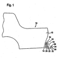
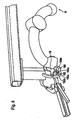
- a first embodiment of a trailer coupling according to the invention is, as in Fig. 1 shown mounted on a vehicle body 10, between a rear side 14 of the rear portion 12 and a bumper 16.
- a bearing element 20 of the trailer coupling is arranged, which is held by a connected to the vehicle body 10 cross member 24, which also extends in the intermediate space 18.
- the trailer element 20 a designated as a whole with 30 trailer element is movably mounted, wherein the trailer element has a ball neck 32 which carries a coupling ball 36 at a first end 34.
- the coupling ball 36 is arranged so that they is cut symmetrically from a longitudinal center plane 38 of the vehicle body 10 and thus the longitudinal center plane extends through a ball center 40 of the coupling ball 36.
- At least one first region 42 of the ball neck 32 extending from the first end 34 of the ball neck 32 likewise extends symmetrically with respect to the longitudinal center plane 28 and subsequently leads by means of a bend 44 to a second end 48 of the ball neck 32.
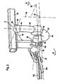
- the hitch 30 is in turn pivotally mounted about a pivot axis 52 on the bearing element 20 by means of a designated as a whole with 50 pivot bearing, wherein the hitch 30 by pivoting about the pivot axis 52 either in the in Fig. 2 shown working position A is positionable or in an in Fig. 3 illustrated substantially by the bumper 16 and lying in the space 18 rest position R, wherein a pivoting movement about the pivot axis 52 from the working position A in the rest position R in an anticlockwise direction of pivoting direction 54 takes place by an angle of more than 180 ° and in reversed a pivoting movement from the rest position R in the working position A takes place clockwise.
- the pivot axis 52 extends, as in Fig. 2 and 3 shown, obliquely to the longitudinal center plane 38 and preferably also obliquely to a horizontal plane 58, and in contrast to the horizontal plane 58 opposite to a direction of travel falling.
- the ball neck 32 emerges during pivoting between the working position A and the rest position R respectively below the lower edge 22 of the bumper 16 therethrough.
- the pivot bearing 50 is formed by a receiving body encompassed by the bearing element 20, which, starting from an opening 62 facing the ball neck 32, has a first receiving surface 64 which is cylindrical relative to the pivot axis 52 and a second cylindrical surface 62 facing away from the opening 62 of the first cylindrical receiving surface 64
- Receiving surface 66 which has a smaller diameter than the first cylindrical receiving surface, and which in continuation of the second cylindrical receiving surface 66 has a third cylindrical receiving surface 68 with also opposite the second cylindrical receiving surface 66 reduced diameter, on one of the first cylindrical receiving surface 64 opposite Side of the second cylindrical receiving surface 66 is arranged.
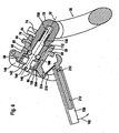
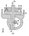
- the receiving body 60 sits a designated as a whole with 70 bearing body, which in an in Fig. 4 illustrated fixing position with a first to its longitudinal axis 71 and thus also to the pivot axis 52 cylindrical surface 74 abuts against the first cylindrical receiving surface 64 which rests with a second to the pivot axis 52 cylindrical surface 76 on the second cylindrical receiving surface 66 and which with a third cylindrical surface 78 abuts against the third cylindrical receiving surface 68.
- bearing body 70 continues beyond the third cylindrical lateral surface 78 with a guide section 80, which extends up to a second end 82 of the bearing body 70 opposite the first end 72 of the bearing body 70.
- locking body 88 of a generally designated 90 blocking means which are movable in a direction of movement 92 transversely to the pivot axis 52 in such a way that provided with these in an insert body 94 of the bearing element 20 and by a formed around the pivot axis 52 circumferential groove 96 locking surfaces 98 are engaged behind, which extend obliquely to the direction of movement 92.
- the insert body 94 is arranged in the bearing element 20, that this adjoins the receiving body 60 and preferably in a recess 102 which extends from one of the opening 62 opposite opening 104 of the bearing element 20 into this hineinerstreckt, so that the insert body 94th is held concentrically to the pivot axis 52 in the bearing element 20 and extends with an adjoining the groove 96 cylindrical inner surface 106 in alignment with the third cylindrical receiving surface 68 up to an opening 108.
- a blocking body drive designated as a whole by 110 which has a drive element 112 which extends into the bearing body 70 starting from an opening 118 provided at the end 82 and up to the first end 72 extending, preferably to the pivot axis 52 coaxial receiving bore 114 is arranged and in this relative to the bearing body 70 in an activation direction 116 is displaceable.
- the drive element 112 has to move the locking body 88 on a drive link 120, which is a receptacle 122 for the locking body 88, a subsequent to the receptacle 122 sliding surface 124 for the locking body 88 and a subsequent to the sliding surface 124 wedge surface 126 for the locking body 88th includes.
- the drive element 112 of the blocking body drive is further provided with a guide pin 128 which engages in an interior of an elastic force accumulator 130 which is supported on a bottom 132 of the receiving bore 114 on the one hand and on the other hand, the drive element 112 in the region of an annular flange 134 with a force so applied in that the drive element 112 always has the tendency to shift so far in the direction of an active position that the drive link 120 with the wedge surface 126 acts on the blocking bodies 88 which are in the blocking position and thus the blocking bodies 88 always act with a force against the blocking surfaces 98, as shown in FIG Fig. 4 is shown, so that the bearing body 70 is retracted as far as possible in the fixing position in the receiving body 60.
- the blocking device 90 comprises a generally designated 140 actuator, which has an integrally formed on the drive member 112 actuator 142, which is coaxial with the pivot axis 52 in continuation of the drive member 112 through the opening 118 and the second End 82 of the bearing body 70 (2014)erstreckt and is connected via a hinge 144 with a guide lever 146 which is mounted on one side of the bearing member 20 with a pivot joint 148 and extending from the pivot joint 148 over the opening 108 of the bearing member 20 and on his the Swivel joint 148 opposite side carries an actuating lever 150.
- the guide lever 146 By acting on the actuating lever 150 in a pulling direction 152, the guide lever 146 moves in the direction of the opening 108 and thus an action on the actuating element 142 in an actuating direction 144, in which the actuating element 142, the drive element 112 of the blocking body drive 110 against the action of the elastic force accumulator 130 einschiebt in the receiving bore 114.
- the Antriebskulisse 120 acts on the locking body 88 no longer with the wedge surfaces 126 but first with the sliding surfaces 124 and is then pushed further until, as in Fig. 5 illustrated, the locking body 88 can dive into the receptacle 122 and thus can move from its blocking position into its release position in which the locking body 88 no longer survive beyond the outside of the guide portion 80, so that the guide portion 80 in the direction of the third cylindrical receiving surface 68 is displaceable, as in Fig. 6 shown.
- the entire bearing body 70 is moved to a pivot position, in which the entire trailer element 30 is freely rotatable about the pivot axis 52.
- the first cylindrical lateral surface 74 is displaced so far that it is arranged offset in the direction of the longitudinal axis 71 relative to the first cylindrical receiving surface 64.
- the form-fitting body 160 has two wedge-shaped mutually exclusive form-locking surfaces 170a, 170b, which can be applied to corresponding form-locking surfaces 162a, 162b of the working position-side form-fitting receptacle 162, so that thereby upon application of the form-locking body 160 in the direction of displacement 156 in the direction of the fixing position, the first form-locking surfaces 170a, 170b can be at the form-locking surfaces 172a, 172b of the working position-side positive connection 162 create free of play.
- the positive locking body 160 opposite another first positive locking element in the form of another positive locking body 180 is provided, which is recognizable only in the rest position R due to the perspective view.
- This further form-fitting body 180 is formed in principle the same as the positive-locking body 160 and, as in Fig. 8 shown, in the rest position R in another third positive engagement element in the form of a rest-side positive locking receptacle 182 inserted. Also, the other positive locking body 180 has positive engagement surfaces 190a, 190b, which are engageable with positive engagement surfaces 192a, 192b of reststaubungs reliablen form-fitting receptacle 182 upon displacement of the same from the pivoting position into the fixing position.
- the pivoting movement about the pivot axis 52 from the working position to the rest position includes a rotational movement in particular by about 180 ° and more and two opposing positive-locking body 160 and 180 are provided, in addition to prevent the first positive-locking body 160 in, for example, the rest side rest side Positive locking receptacle 182 engages, the first positive locking body 160 still with a guide pin 200th provided, which is assigned to a bearing element 20 provided on the guide track 202, which only in the working position A and - not shown in the drawing - in the rest position R has a recess 204 into which the guide pin 200 can dip.
- the guide pin 200 which can be supported on the guide track 202 outside the working position A and the rest position R, ensures that the first positive locking body 160 only in the working position A in the rest position R in the direction of displacement 156 from the pivot position in the Fixing position can move and thus can only enter into the intended for this job-side positive locking receptacle and rest toos workede recording.
- the guide pin 200 and the guide track 202 thus prevent that the bearing body 70 can move in all intermediate positions between the working position A and the rest position R of the pivot position in the fixing position.
- the bearing body 70 can rotate about the pivot axis 52, while the actuator 142 and the drive member 112 by the guide lever 146 rotationally fixed to the pivot axis 52nd be held and thus do not join the rotation, but remain rotationally fixed, while the bearing body 70 rotates with the locking bodies 88 around the drive member 112 around.
- the hitch 30 by turning about the pivot axis 52, the working position A or the rest position R so the guide pin 200 has the ability to immerse in the recess 204, provided that the hitch 30 opposite to the direction of displacement 156 is applied manually.
- drive element 112 has the ability to move the drive link 120 so far that the displacement surface 124th the locking body 88 moves from its release position in the direction of movement 92 to the blocking position and further, the drive element 112 move so far that after reaching the blocking position of the locking body 88, the drive link 120 is moved relative to this far enough that the wedge surfaces 126 on the locking body 88th Act.
- FIG Fig. 9 to 12 shown in FIG Fig. 9 to 12 are those elements which are identical to those of the first embodiment, provided with the same reference numerals, so that with respect to the description of the same can be fully incorporated by reference to the comments on the first embodiment.
- a locking pin 220 is provided instead of the locking lever 210 on the actuating lever 150 ', which is displaceable by a compression spring 222 in the direction of a provided in the bearing element 20 bolt receptacle 224 and engages in the fixing position in this.
- a handle member 226 is provided with which can be acted on the locking pin 220 such that it is in a release direction 228 relative to the actuating lever 150 'as far as possible that this leaves the bolt receptacle 224 and thus the Operating lever 150 'in the manner described above in the pulling direction 152 is pivotable to move by means of the actuating element 142, the drive member 112 in the actuating direction 154 opposite to the force of the elastic force accumulator 130 in its inactive position and at the same time the bearing body 70 relative to the receiving body 60 of the Fixing position to move in the pivot position, in which a pivoting of the same in the same manner as described in connection with the first embodiment, is possible.
- the actuating device 140 ' in particular the guide lever 146 is not actuated directly by the actuating lever 150, but via a cable device 230, which makes it possible to transmit via a cable 232, the force to a provided from a suitable location operating lever.
- the third embodiment is formed in the same manner as the first embodiment, so that with respect to the other elements is fully incorporated by reference to the comments on the first embodiment and also the same parts are provided with the same reference numerals.
- the actuator 140 is designed as a rotary drive and comprises as actuator 142 'a rack 242 which is in engagement with a pinion 244 of a drive shaft 246, wherein the drive shaft 246 by a rotary drive 248 with a freewheel 250 and a latching device 252 can be driven.
- the freewheel 250 is formed by a freewheel disk 254, which, as in Fig. 14 illustrated, a driver 256 carries, which engages in a cam groove 258 of a driver disc 260 which is rotatably mounted relative to the freewheel disk 254 and rotatably mounted on the drive shaft 246.
- the Mit supportiveut 258 has, as in Fig. 15 shown, a first end 262 and a second end 264, between which the driver 256 can move freely in the cam groove 258.
- the drive plate 260 is provided on its outer peripheral side with a control link 266, with which a control pin 268 of a latching body 270 of the latching device 252 is displaceable, to the effect that the latching body 270 against the force of a spring 272 in a Ausrastraum 274 is movable.
- the latching body 270 further has a latching nose 276, which can then be brought into engagement with a latching recess 278 in the freewheel disk 254 when the non-rotatably coupled to the drive shaft 246 freewheel disk 254 is in a position corresponding to the active position of the drive member 112. In this position, the rotational movement of the freewheel disk 254 is blocked by the latching lug 276 of the latching body 270 and thus also the actuating element 142 'secured against movement in the actuating direction 154.
- the driver disk 260 may first be rotated in a direction of rotation 280 until the driver 256 abuts against the end 262 of the driver groove 258 ( Fig. 16 ). This way is sufficient to act on the control pin 268 of the locking body 270 by means of the control cam 266 and thus to move the locking body 270 against the force of the spring 272 in the unlocking direction 274 and consequently to release the rotational movement of the freewheel disk 254.
- the freewheel disk 254 is entrained in that the driver 256 abuts against the end 262 of the cam groove 258 and is further rotated with the drive plate 260, as in Fig. 16 and 17 shown.
- the pulling action on the cable 278 can now be omitted and the drive plate 260 has the ability to turn back by a torsion spring 282 opposite to the direction of rotation 280 in its initial position, while the freewheel disk 254 with the driver 256 in one of the inactive Position of the drive member 112 and the pivot position of the trailer member 30 can remain corresponding position until the hitch 30 is moved either in the working position A or the rest position R back in the direction of displacement 156 in the fixing position and the drive member 112 in the fixing position in its active Position changes.
- the driver 256 is free in the in Fig. 15 moved back position shown and there is again a rotationally fixed locking the freewheel disk 254 characterized in that the locking lug 276 of the locking body 270 dips into the recess 278.
Abstract
Description
Anhängekupplung für Kraftfahrzeuge umfassend ein Lagerelement, ein gegenüber dem Lagerelement zwischen einer Arbeitsstellung und einer Ruhestellung um eine Schwenkachse eines Schwenklagers verschwenkbares und zumindest in der Arbeitsstellung zwischen einer Schwenkstellung und einer Fixierstellung in Richtung der Schwenkachse verschiebbares Anhängeelement und eine Fixiereinrichtung, mit welcher das Anhängeelement zumindest in der Arbeitsstellung bei Erreichen der Fixierstellung unbewegbar am Lagerelement fixierbar ist.Trailer coupling for motor vehicles comprising a bearing element, a relative to the bearing element between a working position and a rest position about a pivot axis of a pivot bearing pivotable and at least in the working position between a pivot position and a fixing position in the direction of the pivot axis sliding attachment element and a fixing device with which the trailer element at least in the working position upon reaching the fixing position immovable on the bearing element is fixable.
Derartige Anhängekupplungen sind beispielsweise aus der
Bei diesen ist die Fixierung des Anhängeelements in der Fixierstellung mit großem Bedienungskomfort, konstruktiv jedoch komplex gelöst.In these, the fixation of the trailer element in the fixing position with great ease of use, but structurally solved complex.
Der Erfindung liegt daher die Aufgabe zugrunde, eine Anhängekupplung mit vereinfachter Fixierung des Anhängeelements am Lagerelement zu schaffen.The invention is therefore an object of the invention to provide a trailer hitch with simplified fixation of the trailer element on the bearing element.
Diese Aufgabe wird bei einer Anhängekupplung erfindungsgemäß durch die Merkmale des Anspruchs 1 gelöst.This object is achieved in a trailer coupling according to the invention by the features of claim 1.
Der Vorteil der erfindungsgemäßen Lösung ist darin zu sehen, daß mit dem Vorsehen eines Sperrkörpers und einer Sperrfläche eine einfache Möglichkeit einer Blockierung des Lagerkörpers in der Fixierstellung gegeben ist, die außerdem eine ausreichende Funktionssicherheit in der Sperrstellung des Sperrkörpers bietet.The advantage of the solution according to the invention is the fact that with the provision of a locking body and a locking surface a simple way of blocking the bearing body is given in the fixing position, which also provides sufficient reliability in the locked position of the locking body.
Zur sicheren Fixierung des Anhängeelements am Lagerelement ist vorgesehen, daß der Lagerkörper das Anhängeelement sowohl in der Schwenkstellung als auch in der Fixierstellung gegenüber dem Aufnahmekörper lagert, wobei die Lagerung in der Schwenkstellung eine drehbare Lagerung darstellt, während in der Fixierstellung die Lagerung des Lagerkörpers in dem Aufnahmekörper im Sinne einer sicheren Abstützung des Anhängeelements gegenüber dem Lagerelement erfolgt.For secure fixation of the trailer element on the bearing element is provided that the bearing body supports the trailer element both in the pivot position and in the fixing position relative to the receiving body, wherein the storage in the pivot position is a rotatable storage, while in the fixing position, the storage of the bearing body in the Receiving body in the sense of a secure support of the trailer element relative to the bearing element takes place.
Eine besonders günstige Ausbildung des Anhängeelements sieht vor, daß dieses ein erstes, die Kupplungskugel tragendes Ende sowie ein zweites freies Ende aufweist.A particularly advantageous embodiment of the trailer element provides that this has a first, the coupling ball bearing end and a second free end.
Hinsichtlich der Anordnung des Lagerkörpers wurden ebenfalls keine näheren Angaben gemacht. So ist vorzugsweise vorgesehen, daß der Lagerkörper an dem Anhängeelement zwischen dem Kugelhals und dem freien Ende angeordnet ist.With regard to the arrangement of the bearing body, no further details were given. Thus, it is preferably provided that the bearing body is arranged on the trailer element between the ball neck and the free end.
Ferner wurden auch hinsichtlich der Ausbildung des Aufnahmekörpers keine weiteren Angaben gemacht. Besonders günstig ist es, wenn der Aufnahmekörper eine erste Öffnung aufweist, durch welche der Lagerkörper ausgehend vom Kugelhals in den Aufnahmekörper eingreift, und eine zweite, der ersten Öffnung gegenüberliegende Öffnung.Furthermore, no further details were given as regards the training of the host body. It is particularly favorable when the receiving body has a first opening, through which the bearing body engages in the receiving body starting from the ball neck, and a second opening opposite the first opening.
Um den Sperrkörper in einfacher Weise von der Freigabestellung in die Sperrstellung bewegen zu können, ist vorgesehen, daß die Blockiereinrichtung einen Sperrkörperantrieb aufweist, mit welchem der Sperrkörper von einer diesen von der Freigabestellung in Richtung der Sperrstellung bewegenden Kraft beaufschlagbar ist.In order to move the locking body in a simple manner from the release position to the blocking position, it is provided that the blocking device has a blocking body drive, with which the locking body can be acted upon by a force moving from the release position in the direction of the blocking position.
Ein derartiger Sperrkörperantrieb kann in unterschiedlichster Art und Weise ausgebildet sein.Such a blocking body drive can be designed in various ways.
Beispielsweise wäre es denkbar, den Sperrkörper unmittelbar mit einer Druckfeder zu beaufschlagen.For example, it would be conceivable to apply the locking body directly with a compression spring.
Eine besonders zweckmäßige Lösung sieht vor, daß der Sperrkörperantrieb das Antriebselement aufweist, mit welchem der Sperrkörper von der Freigabestellung in die Sperrstellung bewegbar ist.A particularly expedient solution provides that the blocking body drive has the drive element, with which the locking body is movable from the release position into the blocking position.
Dabei ist das Antriebselement durch den elastischen Kraftspeicher beaufschlagt, so daß die Möglichkeit besteht, das Antriebselement stets mit der Kraft des elastischen Kraftspeichers beaufschlagt zu halten und somit stets auf den Sperrkörper wirksam werden kann.In this case, the drive element is acted upon by the elastic force accumulator, so that there is the possibility of keeping the drive element always acted upon by the force of the elastic force accumulator and thus can always be effective on the locking body.
Hinsichtlich der Bewegungsmöglichkeiten des Antriebselements wurden bislang keine näheren Angaben gemacht.With regard to the possibilities of movement of the drive element so far no further details have been made.
So wäre es beispielsweise denkbar, das Antriebselement so auszubilden, daß durch Relativverdrehung desselben zum Sperrkörper ein Verschieben des mindestens einen Sperrkörpers möglich ist.Thus, it would be conceivable, for example, the drive element in such a way that by relative rotation thereof to the locking body, a displacement of the at least one locking body is possible.
Als konstruktiv günstig hat sich erwiesen, wenn das Antriebselement in einer Aktivierungsrichtung relativ zu dem dieses aufnehmenden Element, also im Fall der Aufnahme des Antriebselements im Lagerkörper relativ zum Lagerkörper, verschiebbar angeordnet ist, da mit einer derartigen Linearverschiebbarkeit in einfacher Weise der Sperrkörper betätigbar ist.As has been found to be structurally favorable when the drive element in an activation direction relative to the receiving element, ie in the case of receiving the drive element in the bearing body relative to the bearing body, slidably disposed as with such Linearverschiebbarkeit in a simple manner, the blocking body can be actuated.
Die Betätigung des Sperrkörpers läßt sich dabei günstig und sicher dadurch realisieren, wenn das Antriebselement eine Antriebskulisse mit einer Aufnahme aufweist, in welche der mindestens eine Sperrkörper in der Freigabestellung eintaucht, und eine Verschiebefläche mit welcher der mindestens eine Sperrkörper von der Freigabestellung in die Sperrstellung bewegbar ist. Mit einer derartigen Verschiebefläche läßt sich in einfacher Weise und insbesondere sicher der Sperrkörper von der Freigabestellung in die Sperrstellung bewegen.The actuation of the locking body can thereby be realized in a favorable and secure manner when the drive element has a drive link with a receptacle into which the at least one locking body dips in the release position, and a sliding surface with which the at least one locking body can be moved from the release position into the blocking position is. With such a sliding surface can be in a simple Way and in particular safely move the locking body of the release position in the locked position.
Um auch den Sperrkörper in der Sperrstellung nicht nur zu halten, sondern beim Auftreten von Spiel den Sperrkörper nachstellend in Richtung der Sperrfläche bewegen zu können, ist vorzugsweise vorgesehen, daß sich an die Verschiebefläche eine Keilfläche anschließt, welche den Sperrkörper in der Sperrstellung in der Bewegungsrichtung nachstellend beaufschlagt.In order not only to hold the locking body in the locked position, but to be able to move the locking body in the direction of the blocking surface when play occurs, it is preferably provided that adjoins the sliding surface a wedge surface, which the locking body in the blocking position in the direction of movement adjoining acted upon.
Um auch ein durch verschleißbedingtes Spiel zu vermeiden, ist es besonders günstig, wenn die Blockiereinrichtung auf die formschlüssigen Fixierelemente spielfrei nachstellend wirkt, so daß jedes durch Verschleiß auftretende Spiel ebenfalls wiederum durch die nachstellende Wirkung der Blockiereinrichtung vermieden werden kann.In order to avoid a wear-related game, it is particularly advantageous if the blocking device acts on the positive fixing without play adjusting, so that any game occurring due to wear can also be avoided in turn by the adjusting effect of the blocking device.
Als besonders vorteilhaft hat es sich erwiesen, wenn die Blockiereinrichtung in der Sperrstellung des mindestens einen Sperrkörpers aufgrund dessen Zusammenwirken mit der Sperrfläche den Lagerkörper in Richtung der Fixierstellung kraftbeaufschlagt, so daß dadurch eine dauerhafte feste Fixierung des Anhängeelements in dem Lagerelement erreichbar ist.It has proven to be particularly advantageous if the blocking device in the blocking position of the at least one locking body due to its interaction with the locking surface the bearing body in the direction of the fixing force, so that thereby a permanent fixed fixing of the trailer element in the bearing element can be achieved.
Besonders günstig ist es dabei, wenn die Blockiereinrichtung formschlüssige Fixierelemente der Fixiereinrichtung in spielfreier Anlage hält und somit auch insgesamt die Fixierung des Anhängeelements spielfrei relativ zum Lagerelement erfolgen kann.It is particularly advantageous if the blocking device holds positive fixing elements of the fixing in play-free system and thus also the fixation of the hitch element can be done free of play relative to the bearing element.
Das Zusammenwirken des Sperrkörpers mit der Sperrfläche ergibt in besonders einfacher Weise eine Beaufschlagung des Lagerkörpers in Richtung der Fixierstellung, wenn die Sperrfläche schräg oder geneigt zur Bewegungsrichtung verläuft.The interaction of the locking body with the locking surface results in a particularly simple manner, an actuation of the bearing body in the direction of the fixing position when the locking surface is inclined or inclined to the direction of movement.
Konstruktiv ist vorgesehen, daß der mindestens eine Sperrkörper und der Sperrkörperantrieb in dem Lagerkörper angeordnet ist und somit mit dem Lagerkörper mitbewegbar ist.Structurally, it is provided that the at least one locking body and the blocking body drive is arranged in the bearing body and thus is mitbewegbar with the bearing body.
Eine derartige Lösung hat noch den Vorteil, daß damit eine sehr raumsparende Integration des Sperrkörpers und des Sperrkörperantriebs möglich ist.Such a solution has the advantage that it allows a very space-saving integration of the locking body and the blocking body drive.
Ferner ist es günstig, wenn in dem Lagerkörper der mindestens eine Sperrkörper zwischen der Freigabestellung und der Sperrstellung in einer Bewegungsrichtung quer zur Verschieberichtung desselben bewegbar geführt ist.Further, it is advantageous if the at least one locking body between the release position and the blocking position in a movement direction transverse to the displacement direction of the same is movably guided in the bearing body.
Hinsichtlich der Ausbildung der Blockiereinrichtung im Hinblick auf eine Betätigung des Sperrkörperantriebs wurden bislang keine weiteren Angaben gemacht. So ist jede denkbare Betätigung des Sperrkörperantriebs möglich.With regard to the formation of the blocking device with regard to an actuation of the blocking body drive, no further details have been given so far. So every conceivable operation of the locking body drive is possible.
Außerdem ist vorgesehen, daß die Blokiereinrichtung eine auf den Sperrkörperantrieb wirkende Betätigungseinrichtung umfaßt, mit welcher auf das Antriebselement entgegen der Kraftwirkung des elastischen Kraftspeichers einwirkbar ist, und daß im Hinblick auf eine vorteilhafter Bedienbarkeit der Betätigungseinrichtung die Betätigungseinrichtung am Lagerelement angeordnet ist und der Sperrkörperantrieb am Anhängeelement.It is also provided that the Blokiereinrichtung comprises acting on the locking body actuator, with which the drive element against the force of the elastic force storage is acted upon, and that in terms of an advantageous operability of the actuator, the actuator is arranged on the bearing element and the blocking body drive on the trailer ,
In diesem Falle ist es zweckmäßig, wenn ein Betätigungselement der Betätigungseinrichtung über das freie Ende des Anhängeelements übersteht und somit über das Betätigungselement ein Einwirken auf das Antriebselement möglich ist.In this case, it is expedient if an actuating element of the actuating device projects beyond the free end of the trailer element and thus an action on the drive element is possible via the actuating element.
Zweckmäßigerweise ist hierzu das Betätigungselement koaxial zur Schwenkachse angeordnet, so daß sich ein Drehen des Anhängeelements um die Schwenkachse in einfacher Weise konstruktiv abfangen läßt.Conveniently, for this purpose, the actuating element is arranged coaxially to the pivot axis, so that a rotation of the trailer element about the pivot axis can be intercepted constructively in a simple manner.
Beispielsweise wäre es denkbar, das Betätigungselement mit einer Drehkupplung zu versehen.For example, it would be conceivable to provide the actuating element with a rotary coupling.
Konstruktiv besonders einfach ist es jedoch, wenn das Betätigungselement um die Schwenkachse drehbar im Anhängeelement gelagert ist.It is structurally particularly simple, however, if the actuating element is mounted rotatably about the pivot axis in the trailer element.
Die Einwirkung auf den Sperrkörperantrieb läßt sich besonders einfach realisieren, wenn das Betätigungselement zum Aufheben der auf das Antriebselement wirkenden Kraft des elastischen Kraftspeichers in seinem über das freie Ende des Anhängeelements überstehenden Bereich in Richtung des freien Endes des Anhängeelements beaufschlagbar ist.The action on the blocking body drive can be realized in a particularly simple manner if the actuating element can be acted upon in the direction of the free end of the attachment element in order to cancel the force of the elastic force store acting on the drive element in its region projecting beyond the free end of the attachment element.
Besonders günstig ist es ferner, wenn mit der Betätigungseinrichtung bei in Freigabestellung stehendem Sperrkörper das Anhängeelement von der Fixierstellung in die Schwenkstellung verschiebbar ist, so daß die Betätigungseinrichtung nicht nur dazu eingesetzt wird, auf den Sperrkörperantrieb einzuwirken, um den mindestens einen Sperrkörper von der Sperrstellung in die Freigabestellung zu bewegen, sondern gleichzeitig die Betätigungseinrichtung auch noch dazu eingesetzt werden kann, das Anhängeelement von der Fixierstellung aktiv in die Schwenkstellung zu verschieben.It is also particularly advantageous when with the actuator in standing in the release position blocking body, the trailer element from the fixing position is displaced into the pivot position, so that the actuator is not only used to act on the locking body drive to the at least one locking body from the blocking position in move the release position, but at the same time the actuator can also be used to actively move the hitch from the fixing position in the pivot position.
Darüber hinaus läßt sich die Betätigungseinrichtung vorteilhafterweise nicht nur dazu einsetzen, das Anhängeelement in die Schwenkstellung zu verschieben, sondern auch dazu, das Anhängeelement in der Schwenkstellung in der Verschieberichtung definiert zu positionieren, das heißt in der Verschieberichtung in einer definierten, der Schwenkstellung zugeordneten Position relativ zum Lagerelement zu halten, so daß der Lagerkörper die Möglichkeit hat, gemeinsam mit dem Aufnahmekörper das Schwenklager für das Anhängeelement zu bilden.In addition, the actuator can advantageously not only be used to move the hitch in the pivoting position, but also to define the hitch in the pivot position defined in the direction of displacement, that is, in the direction in which a defined, the pivot position associated position relative to hold the bearing element, so that the bearing body has the opportunity to form together with the receiving body, the pivot bearing for the trailer element.
Die Einwirkung der Betätigungseinrichtung auf das Betätigungselement kann dabei in unterschiedlichster Art und Weise erfolgen.The action of the actuator on The actuator can be done in different ways.
So sieht eine Ausführungsform vor, daß das Betätigungselement mit einem Führungshebel der Betätigungseinrichtung gekoppelt ist.Thus, an embodiment provides that the actuating element is coupled to a guide lever of the actuating device.
Beispielsweise ist im Fall der Anordnung der Betätigungseinrichtung am Lagerelement vorgesehen, daß der Führungshebel an dem Lagerelement schwenkbar gelagert ist, so daß durch Verschwenken des Führungshebels unter Ausnutzung der Hebelgesetze eine Einwirkung auf das Betätigungselement erfolgen kann.For example, in the case of the arrangement of the actuating device provided on the bearing element, that the guide lever is pivotally mounted on the bearing element, so that by pivoting the guide lever taking advantage of the leverage laws can be made to act on the actuator.
Alternativ dazu ist vorgesehen, daß das Betätigungselement als Zahnstange ausgebildet ist, welche mit einem Zahnritzel der Betätigungseinrichtung kämmt, so daß mit der Betätigungseinrichtung die Möglichkeit besteht, durch Drehen des Zahnritzels auf das Betätigungselement einzuwirken.Alternatively, it is provided that the actuating element is designed as a rack, which meshes with a pinion of the actuating device, so that with the actuating device is possible to act by turning the pinion on the actuating element.
Hinsichtlich der Ausbildung der Betätigungseinrichtung selbst wurden bislang keine näheren Angaben gemacht. So ist jede Betätigungseinrichtung mit einem Einwirkungselement, vorzugsweise zur manuellen Einwirkung auf das Betätigungselement, versehen.With regard to the design of the actuator itself so far no details have been made. Thus, each actuator is provided with an action element, preferably for manual action on the actuator.
Um die Möglichkeit zu schaffen, die manuelle Einwirkung vor Rückkehr des Anhängeelements in die Fixierstellung zu beenden, insbesondere um die Möglichkeit zu schaffen, nur dazu manuell auf die Betätigungseinrichtung einzuwirken, daß das Anhängeelement von der Fixierstellung in die Schwenkstellung übergeht, ist es zweckmäßig, wenn die Betätigungseinrichtung mit einem zwischen dem Betätigungselement und dem Einwirkungselement vorgesehenen Freilauf versehen ist.In order to provide the possibility to end the manual action before returning the hitch element in the fixing position, in particular to create the possibility of acting only manually on the actuator that the hitch goes from the fixing position in the pivot position, it is useful if the actuating device is provided with a freewheel provided between the actuating element and the action element.
Hinsichtlich der Frage, ob die Freigabestellung der Sperrkörper in der Schwenkstellung aufrecht erhalten wird oder nicht, wurden bislang keine näheren Angaben gemacht. So wäre es beispielsweise denkbar, den mindestens einen Sperrkörper in der Freilaufstellung wieder in eine Sperrstellung zu überführen, in welcher dieser die Schwenkstellung definiert aufrecht erhält.Regarding the question of whether the release position of the locking body is maintained in the pivot position or not, no details have been given so far. So it would be conceivable, for example, to convert the at least one locking body in the freewheeling position again in a blocking position in which this defines the pivot position is maintained.
Eine andere Möglichkeit sieht vor, den mindestens einen Sperrkörper durch Verrasten des Antriebselements relativ zum Lagerkörper festzulegen und somit die Kraftwirkung des elastischen Kraftspeichers des Sperrkörperantriebs auf den Sperrkörper zu blockieren.Another possibility provides to fix the at least one locking body by locking the drive element relative to the bearing body and thus to block the force of the elastic force accumulator of the locking body drive on the locking body.
Eine besonders einfache Möglichkeit sieht jedoch vor, daß der Aufnahmekörper in der Schwenkstellung des Anhängeelements den mindestens einen Sperrkörper in der Freigabestellung hält.However, a particularly simple possibility provides that the receiving body in the pivoting position of the trailer element holds the at least one locking body in the release position.
Besonders einfach läßt sich dies dadurch realisieren, daß der Aufnahmekörper eine auf den mindestens einen Sperrkörper wirkende Fläche aufweist.This can be realized in a particularly simple manner in that the receiving body has a surface acting on the at least one blocking body.
Hinsichtlich der speziellen Ausbildung der Blockiereinrichtung, insbesondere bei Anordnen des Sperrkörperantriebs und der Sperrkörper am Anhängeelement wurden bislang keine näheren Angaben gemacht. So sieht eine zweckmäßige Lösung vor, daß der mindestens eine Sperrkörper auf einer dem Kugelhals abgewandten Seite des Lagerkörpers am Anhängeelement vorgesehen ist.With regard to the special design of the blocking device, in particular when arranging the blocking body drive and the locking body on the trailer element so far no further details have been made. Thus, an expedient solution that the at least one locking body is provided on a side facing away from the ball neck of the bearing body on the trailer element.
Zweckmäßigerweise ist der mindestens eine Sperrkörper in seitlichen Führungsöffnungen des Anhängeelements in der Bewegungsrichtung geführt angeordnet.Conveniently, the at least one locking body is arranged guided in lateral guide openings of the trailer in the direction of movement.
Die Führungsöffnungen können prinzipiell an beliebiger Stelle des Anhängeelements angeordnet sein. Besonders zweckmäßig ist es, wenn die seitlichen Führungsöffnungen nahe des freien Endes des Anhängeelements angeordnet sind.The guide openings can in principle be arranged at any point of the trailer element. It is particularly expedient if the lateral guide openings are arranged near the free end of the trailer element.
Zum Anordnen des Antriebselements in dem Anhängeelement wurden ebenfalls keine weiterführenden Angaben gemacht. So ist vorzugsweise vorgesehen, daß das Antriebselement in einer Ausnehmung im Anhängeelement angeordnet ist.For arranging the drive element in the trailer element also no further details were made. Thus, it is preferably provided that the drive element is arranged in a recess in the trailer element.
Günstigerweise ist dabei die Ausnehmung so ausgebildet, daß sie sich von einer am freien Ende des Anhängeelements vorgesehenen Öffnung in das Anhängeelement hineinerstreckt.Conveniently, while the recess is formed so that it extends from an opening provided at the free end of the trailer element opening in the trailer element.
Die Ausnehmung könnte dabei parallel oder schräg zur Schwenkachse verlaufen.The recess could be parallel or oblique to the pivot axis.
Eine günstige Lösung sieht jedoch vor, daß die Ausnehmung koaxial zur Schwenkachse verläuft.A favorable solution provides, however, that the recess is coaxial with the pivot axis.
Hinsichtlich der Abstützung des elastischen Kraftspeichers, welcher das Antriebselements beaufschlagt, ist zweckmäßigerweise vorgesehen, daß sich der elastische Kraftspeicher auf einem der Öffnung gegenüberliegenden Boden der Ausnehmung abstützt.With regard to the support of the elastic force accumulator, which acts on the drive element, it is expediently provided that the elastic force accumulator is supported on a bottom of the recess opposite the opening.
Hinsichtlich der Fixierung des Anhängeelements relativ zum Lagerelement wurden bislang keine näheren Angaben gemacht.With regard to the fixation of the trailer element relative to the bearing element so far no further details have been made.
So ist alternativ oder ergänzend zu den bislang beschriebenen Ausführungsbeispielen vorgesehen, daß das Lagerelement einen Aufnahmekörper mit einer Öffnung aufweist, von welcher ausgehend ein Lagerkörper des Anhängeelements in den Aufnahmekörper eingreift, und daß das Anhängeelement ein erstes Formschlußelement aufweist, welches in der Schwenkstellung des Anhängeelements außer Eingriff mit einem zweiten am Aufnahmekörper vorgesehenen Formschlußelement steht und welches zumindest in der Arbeitsstellung beim Verschieben des Anhängeelements von der Schwenkstellung in die Fixierstellung mit dem zweiten Formschlußelement des Aufnahmekörpers in Eingriff bringbar ist.Thus, as an alternative or in addition to the embodiments described so far provided that the bearing element has a receiving body with an opening, starting from which a bearing body of the trailer element engages in the receiving body, and that the trailer element has a first positive locking element, which in the pivoting position of the trailer except Engagement with a second provided on the receiving body form-fitting element is and which at least in the working position when moving the trailer element from the pivot position into the fixing position with the second positive locking element of the receiving body can be brought into engagement.
Um das erste und das zweite Formschlußelement einfach in Eingriff bringen zu können, ist bei einer konstruktiv zweckmäßigen Lösung vorgesehen, daß das zweite Formschlußelement auf einer dem Kugelhals zugewandten Seite des Aufnahmekörpers angeordnet ist.In order to bring the first and the second positive locking element easy to engage, is provided in a structurally expedient solution that the second positive locking element is disposed on a ball neck facing side of the receiving body.
Besonders günstig ist es dabei, wenn das zweite Formschlußelement in einem stirnseitigen Bereich des Aufnahmekörpers angeordnet ist.It is particularly advantageous if the second positive locking element is arranged in an end region of the receiving body.
Um das zweite Formschlußelement möglichst einfach herstellen zu können, ist vorzugsweise vorgesehen, daß das zweite Formschlußelement einstückig an dem Aufnahmekörper angeformt ist.In order to produce the second positive locking element as simple as possible, it is preferably provided that the second positive locking element is integrally formed on the receiving body.
Ferner ist zweckmäßigerweise vorgesehen, daß das erste Formschlußelement einstückig an das Anhängeelement angeformt ist.Furthermore, it is expediently provided that the first positive locking element is integrally formed on the trailer element.
Die Position des ersten Formschlußelements ist vorzugsweise so gewählt, daß das erste Formschlußelement im Bereich eines Übergangs vom Kugelhals zum Lagerkörper angeordnet ist.The position of the first positive locking element is preferably selected so that the first positive locking element is arranged in the region of a transition from the ball neck to the bearing body.
Um ferner auch in der Ruhestellung das Anhängeelement formschlüssig fixieren zu können, ist vorzugsweise vorgesehen, daß der Aufnahmekörper ein drittes Formschlußelement aufweist, mit welchem das erste Formschlußelement in der Ruhestellung in Eingriff bringbar ist.In order further to be able to positively fix the hitch element in the rest position, it is preferably provided that the receiving body has a third interlocking element, with which the first interlocking element in the rest position can be brought into engagement.
Zweckmäßigerweise ist dabei das dritte Formschlußelement identisch wie das zweite Formschlußelement ausgebildet.Expediently, the third positive locking element is identical to the second positive locking element.
Um sicherzustellen, daß das Anhängeelement relativ zum Lagerelement nur in der Arbeitsstellung und in der Ruhestellung von der Schwenkstellung in die Fixierstellung übergehen kann, ist vorzugsweise vorgesehen, daß der Lagerkörper eine Führungsbahn aufweist, auf welcher einem Anhängeelement angeordnetes Führungselement aufliegt, wenn das Anhängeelement außerhalb der Arbeitsstellung und der Ruhestellung steht.To ensure that the hitch relative to the bearing element can pass only in the working position and in the rest position of the pivoting position in the fixing position, it is preferably provided that the bearing body has a guide rail on which a trailer mounted guide element rests when the hitch outside the Working position and the resting position.
Weitere Merkmale und Vorteile der Erfindung sind Gegenstand der nachfolgenden Beschreibung sowie der zeichnerischen Darstellung einiger Ausführungsbeispiele.Further features and advantages of the invention are the subject of the following description and the drawings of some embodiments.
In der Zeichnung zeigen:
- Fig. 1
- eine schematische Darstellung eines ersten Ausführungsbeispiels einer erfindungsgemäßen Anhängekupplung montiert an einem Heck eines Fahrzeugs;
- Fig. 2
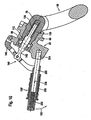
- eine perspektivische Darstellung des ersten Ausführungsbeispiels einer erfindungsgemäßen Anhängekupplung mit in Arbeitsstellung stehendem Anhängeelement;
- Fig. 3
- eine perspektivische Darstellung ähnlich
Fig. 2 mit in Ruhestellung stehendem Anhängeelement; - Fig. 4
- einen Schnitt längs Linie 4-4 in
Fig. 2 bei in Fixierstellung stehendem Anhängeelement; - Fig. 5
- einen Schnitt ähnlich
Fig. 4 unmittelbar nach Überführen von Sperrkörpern in eine Freigabestellung; - Fig. 6
- einen Schnitt ähnlich
Fig. 4 bei Erreichen einer Schwenkstellung des Anhängeelements; - Fig. 7
- eine perspektivische Darstellung ähnlich
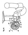
Fig. 2 bei in Schwenkstellung und in Arbeitsstellung stehendem Anhängeelement; - Fig. 8
- eine perspektivische Darstellung ähnlich
Fig. 3 bei in Schwenkstellung und Ruhestellung stehendem Anhängeelement; - Fig. 9
- eine Darstellung ähnlich
Fig. 2 eines zweiten Ausführungsbeispiels einer erfindungsgemäßen Anhängekupplung; - Fig. 10
- einen Schnitt längs Linie 10-10 in
Fig. 9 bei in Fixierstellung verrasteter Betätigungseinrichtung; - Fig. 11
- einen Schnitt ähnlich
Fig. 10 bei gelöster Verrastung der Betätigungseinrichtung; - Fig. 12
- eine Darstellung ähnlich
Fig. 2 eines dritten Ausführungsbeispiels einer erfindungsgemäßen Anhängekupplung; - Fig. 13
- einen Schnitt längs Linie 13-13 durch ein viertes Ausführungsbeispiel einer erfindungsgemäßen Anhängekupplung;
- Fig. 14
- einen Schnitt längs Linie 14-14 in
Fig. 13 ; - Fig. 15
- eine perspektivische Darstellung ähnlich
Fig. 2 des vierten Ausführungsbeispiels der erfindungsgemäßen Betätigungseinrichtung bei vollständiger Blockierung in Fixierstellung; - Fig. 16
- eine Darstellung ähnlich
Fig. 15 bei frei drehbarer Freilaufscheibe; - Fig. 17
- eine Darstellung ähnlich
Fig. 15 bei Einwirken auf ein Antriebselement eines Sperrkörperantriebs mit der Betätigungseinrichtung des vierten Ausführungsbeispiels und - Fig. 18
- eine Darstellung ähnlich
Fig. 15 bei mittels der Betätigungseinrichtung in Schwenkstellung ausgefahrenem Anhängeelement.
- Fig. 1
- a schematic representation of a first embodiment of a trailer coupling according to the invention mounted on a rear of a vehicle;
- Fig. 2
- a perspective view of the first embodiment of a trailer coupling according to the invention with standing in working position trailer element;
- Fig. 3
- a perspective view similar
Fig. 2 with resting trailer element; - Fig. 4
- a section along line 4-4 in
Fig. 2 when in fixation standing trailer element; - Fig. 5
- similar to a cut
Fig. 4 immediately after transferring blocking bodies into a release position; - Fig. 6
- similar to a cut
Fig. 4 upon reaching a pivot position of the trailer element; - Fig. 7
- a perspective view similar
Fig. 2 in standing in pivot position and in working position trailer element; - Fig. 8
- a perspective view similar
Fig. 3 in standing in the swivel position and rest position trailer element; - Fig. 9
- a representation similar
Fig. 2 a second embodiment of a trailer coupling according to the invention; - Fig. 10
- a section along line 10-10 in
Fig. 9 in locked in fixing position actuator; - Fig. 11
- similar to a cut
Fig. 10 when latching the actuator; - Fig. 12
- a representation similar
Fig. 2 a third embodiment of a trailer coupling according to the invention; - Fig. 13
- a section along line 13-13 by a fourth embodiment of a trailer coupling according to the invention;
- Fig. 14
- a section along line 14-14 in
Fig. 13 ; - Fig. 15
- a perspective view similar
Fig. 2 the fourth embodiment of the actuator according to the invention with complete blocking in the fixing position; - Fig. 16
- a representation similar
Fig. 15 with freely rotatable freewheel disk; - Fig. 17
- a representation similar
Fig. 15 when acting on a drive element of a blocking body drive with the actuating device of the fourth embodiment and - Fig. 18
- a representation similar
Fig. 15 in extended by means of the actuator in pivoting position hitch.
Ein erstes Ausführungsbeispiel einer erfindungsgemäßen Anhängekupplung ist, wie in
An dem Lagerelement 20 ist ein als Ganzes mit 30 bezeichnetes Anhängeelement bewegbar gelagert, wobei das Anhängeelement einen Kugelhals 32 aufweist, welcher an einem ersten Ende 34 eine Kupplungskugel 36 trägt. In einer in
Ferner verläuft zumindest ein vom ersten Ende 34 des Kugelhalses 32 ausgehender erster Bereich 42 des Kugelhalses 32 ebenfalls symmetrisch zu der Längsmittelebene 28 und führt anschließend mittels einer Umbiegung 44 zu einem zweiten Ende 48 des Kugelhalses 32.Furthermore, at least one
Das Anhängeelement 30 ist seinerseits mittels eines als Ganzes mit 50 bezeichneten Schwenklagers um eine Schwenkachse 52 am Lagerelement 20 schwenkbar gelagert, wobei das Anhängeelement 30 durch Verschwenken um die Schwenkachse 52 entweder in der in
Die Schwenkachse 52 verläuft dabei, wie in
Wie in
In dem Aufnahmekörper 60 sitzt ein als Ganzes mit 70 bezeichneter Lagerkörper, welcher in einer in
Der Lagerkörper 70 setzt sich ferner noch über die dritte zylindrische Mantelfläche 78 hinaus fort mit einem Führungsabschnitt 80, welcher sich bis zu einem dem ersten Ende 72 des Lagerkörpers 70 gegenüberliegenden zweiten Ende 82 des Lagerkörpers 70 erstreckt.Furthermore, the bearing
In dem Führungsabschnitt 80 sind in quer zur Schwenkachse 52 verlaufenden Führungsöffnungen 84 Sperrkörper 88 einer als Ganzes mit 90 bezeichneten Blockiereinrichtung angeordnet, die in einer Bewegungsrichtung 92 quer zur Schwenkachse 52 bewegbar sind und zwar so, daß mit diesen in einem Einsatzkörper 94 des Lagerelements 20 vorgesehene und durch eine um die Schwenkachse 52 umlaufende Nut 96 gebildete Sperrflächen 98 hintergreifbar sind, welche schräg zur Bewegungsrichtung 92 verlaufen.In the
Dabei ist der Einsatzkörper 94 derart in dem Lagerelement 20 angeordnet, daß dieser sich an den Aufnahmekörper 60 anschließt und vorzugsweise in einer Ausnehmung 102 sitzt, die sich von einer der Öffnung 62 gegenüberliegenden Öffnung 104 des Lagerelements 20 in dieses hineinerstreckt, so daß der Einsatzkörper 94 konzentrisch zur Schwenkachse 52 im Lagerelement 20 gehalten ist und mit einer sich an die Nut 96 anschließenden zylindrischen Innenfläche 106 fluchtend mit der dritten zylindrischen Aufnahmefläche 68 bis zu einer Öffnung 108 verläuft.In this case, the
Zum Bewegen der Sperrkörper 88 in der Bewegungsrichtung 92 ist ein als Ganzes mit 110 bezeichneter Sperrkörperantrieb vorgesehen, welcher ein Antriebselement 112 aufweist, das in einer sich ausgehend von einer an dem Ende 82 vorgesehenen Öffnung 118 in den Lagerkörper 70 hineinerstreckenden und bis zum ersten Ende 72 verlaufenden, vorzugsweise zur Schwenkachse 52 koaxialen Aufnahmebohrung 114 angeordnet ist und in dieser relativ zum Lagerkörper 70 in einer Aktivierungsrichtung 116 verschiebbar ist.For moving the blocking
Das Antriebselement 112 weist zum Verschieben der Sperrkörper 88 eine Antriebskulisse 120 auf, die eine Aufnahme 122 für die Sperrkörper 88, eine sich an die Aufnahme 122 anschließende Verschiebefläche 124 für die Sperrkörper 88 und eine sich an die Verschiebefläche 124 anschließende Keilfläche 126 für die Sperrkörper 88 umfaßt.The
Das Antriebselement 112 des Sperrkörperantriebs ist ferner noch mit einem Führungsstift 128 versehen, welcher in ein Inneres eines elastischen Kraftspeichers 130 eingreift, der sich auf einem Boden 132 der Aufnahmebohrung 114 einerseits abstützt und andererseits das Antriebselement 112 im Bereich eines Ringflansches 134 mit einer Kraft derart beaufschlagt, daß das Antriebselement 112 stets die Tendenz hat, sich so weit in Richtung einer aktiven Stellung zu verschieben, daß die Antriebskulisse 120 mit der Keilfläche 126 die in Sperrstellung stehenden Sperrkörper 88 beaufschlagt und somit die Sperrkörper 88 stets mit einer Kraft gegen die Sperrflächen 98 wirken, wie dies in
Um dem elastischen Kraftspeicher 130 entgegenzuwirken, umfaßt die Blockiereinrichtung 90 eine als Ganzes mit 140 bezeichnete Betätigungseinrichtung, welche ein einstückig an das Antriebselement 112 angeformtes Betätigungselement 142 aufweist, welches sich koaxial zur Schwenkachse 52 in Fortsetzung des Antriebselements 112 durch die Öffnung 118 und über das zweite Ende 82 des Lagerkörpers 70 hinauserstreckt und über ein Gelenk 144 mit einem Führungshebel 146 verbunden ist, welcher auf einer Seite des Lagerelements 20 mit einem Schwenkgelenk 148 gelagert ist und sich ausgehend von dem Schwenkgelenk 148 über die Öffnung 108 des Lagerelements 20 hinwegerstreckt und auf seiner dem Schwenkgelenk 148 gegenüberliegenden Seite einen Betätigungshebel 150 trägt.To counteract the
Durch Beaufschlagen des Betätigungshebels 150 in einer Zugrichtung 152 bewegt sich der Führungshebel 146 in Richtung der Öffnung 108 und somit erfolgt eine Einwirkung auf das Betätigungselement 142 in einer Betätigungsrichtung 144, in welcher das Betätigungselement 142 das Antriebselement 112 des Sperrkörperantriebs 110 entgegen der Wirkung des elastischen Kraftspeichers 130 in die Aufnahmebohrung 114 einschiebt.By acting on the
Damit beaufschlagt die Antriebskulisse 120 die Sperrkörper 88 nicht mehr mit den Keilflächen 126 sondern zunächst mit den Verschiebeflächen 124 und wird dann weiter eingeschoben, bis, wie in
In dieser Stellung ist der gesamte Lagerkörper 70 in eine Schwenkstellung verschoben, in welcher das gesamte Anhängeelement 30 um die Schwenkachse 52 frei drehbar ist.In this position, the
Die freie Drehbarkeit des Anhängeelements 30 in der in
Durch das Verschieben des Lagerkörpers 70 entgegengesetzt zur Verschieberichtung 156 ist beispielsweise die erste zylindrische Mantelfläche 74 so weit verschoben, daß diese in Richtung der Längsachse 71 versetzt gegenüber der ersten zylindrischen Aufnahmefläche 64 angeordnet ist.By moving the bearing
Lediglich die zweite zylindrische Mantelfläche 76 liegt noch in Teilbereichen an Teilbereichen der zweiten zylindrischen Aufnahmefläche 66 an.Only the second cylindrical
Darüber hinaus ist durch das Verschieben des Lagerkörpers 70 entgegengesetzt zur Verschieberichtung 156 ein in
Vorzugsweise weist dabei der Formschlußkörper 160 zwei keilförmig zueinander verlaufende Formschlußflächen 170a, 170b auf, welche an korrespondierende Formschlußflächen 162a, 162b der arbeitsstellungsseitigen Formschlußaufnahme 162 anlegbar sind, so daß dadurch bei Beaufschlagung des Formschlußkörpers 160 in Verschieberichtung 156 in Richtung der Fixierstellung die ersten Formschlußflächen 170a, 170b sich an den Formschlußflächen 172a, 172b der arbeitsstellungsseitigen Formschlußaufnahme 162 spielfrei anlegen lassen.Preferably, the form-fitting
Ferner ist, wie in
Dieser weitere Formschlußkörper 180 ist im Prinzip gleich ausgebildet wie der Formschlußkörper 160 und, wie in
Da die Schwenkbewegung um die Schwenkachse 52 von der Arbeitsstellung in die Ruhestellung eine Drehbewegung insbesondere um ungefähr 180° und mehr umfaßt und zwei gegenüberliegende Formschlußkörper 160 und 180 vorgesehen sind, ist zusätzlich, um zu verhindern, daß der erste Formschlußkörper 160 in beispielsweise die weitere ruhestellungsseitige Formschlußaufnahme 182 einrastet, der erste Formschlußkörper 160 noch mit einem Führungsstift 200 versehen, dem eine am Lagerelement 20 vorgesehene Führungsbahn 202 zugeordnet ist, welche lediglich in der Arbeitsstellung A und - zeichnerisch nicht dargestellt - in der Ruhestellung R eine Ausnehmung 204 aufweist, in welche der Führungsstift 200 eintauchen kann.Since the pivoting movement about the
Somit ist durch den Führungsstift 200, der auf der Führungsbahn 202 sich außerhalb der Arbeitsstellung A und der Ruhestellung R abstützen kann, sichergestellt, daß der erste Formschlußkörper 160 sich nur in der Arbeitsstellung A in der Ruhestellung R in der Verschieberichtung 156 von der Schwenkstellung in die Fixierstellung bewegen kann und somit nur in die für diesen vorgesehenen arbeitsstellungsseitige Formschlußaufnahme und die ruhestellungsseitige Aufnahme eintreten kann.Thus, by the
Der Führungsstift 200 und die Führungsbahn 202 verhindern somit, daß sich der Lagerkörper 70 in allen Zwischenstellungen zwischen der Arbeitsstellung A und der Ruhestellung R von der Schwenkstellung in die Fixierstellung bewegen kann.The
Dadurch wird auch die in
Da außerdem das Betätigungselement 142 koaxial zur Schwenkachse 52 angeordnet ist und auch das Antriebselement 112 koaxial zur Schwenkachse 52 angeordnet ist, kann sich der Lagerkörper 70 um die Schwenkachse 52 drehen, während das Betätigungselement 142 und das Antriebselement 112 durch den Führungshebel 146 drehfest zur Schwenkachse 52 gehalten werden und somit die Drehung nicht mitmachen, sondern drehfest verharren, während sich der Lagerkörper 70 mit den Sperrkörpern 88 um das Antriebselement 112 herum dreht.In addition, since the
Erreicht das Anhängeelement 30 durch Drehen um die Schwenkachse 52 die Arbeitsstellung A oder die Ruhestellung R so hat der Führungsstift 200 die Möglichkeit, in die Ausnehmung 204 einzutauchen, sofern das Anhängeelement 30 entgegengesetzt zur Verschieberichtung 156 manuell beaufschlagt wird.Reached the
Erfolgt die Verschiebung soweit, bis die Sperrkörper 88 wieder die Möglichkeit haben, sich radial nach außen in die Nut 96 hineinzubewegen, so hat gleichzeitig das durch den elastischen Kraftspeicher 130 beaufschlagte Antriebselement 112 die Möglichkeit, die Antriebskulisse 120 soweit zu verschieben, daß die Verschiebefläche 124 die Sperrkörper 88 von ihrer Freigabestellung in der Bewegungsrichtung 92 zur Sperrstellung hin bewegt und ferner kann sich das Antriebselement 112 soweit verschieben, daß nach Erreichen der Sperrstellung der Sperrkörper 88 die Antriebskulisse 120 relativ zu diesen soweit verschoben ist, daß die Keilflächen 126 auf die Sperrkörper 88 wirken.If the displacement so far until the locking
Dadurch, daß nun die Sperrflächen 98 schräg zur Bewegungsrichtung 92 dergestalt verlaufen, daß die sich in der Bewegungsrichtung 92 bewegenden Sperrkörper 88 über ihre Führungsöffnungen 84 so auf den Lagerkörper 70 einwirken, daß dieser eine Kraft entgegengesetzt zur Verschieberichtung 156 in Richtung der Fixierstellung erfährt, bewirkt diese Kraft auch, daß die keilförmig zueinander verlaufenden Formschlußflächen 170a, 170b sowie 172a, 172b sowie die Formschlußflächen 190a und 190b sowie 192a und 192b kraftbeaufschlagt aneinander anliegen und somit spielfrei relativ zueinander gehalten werden, woraus wiederum eine spielfreie und drehfeste Positionierung des Anhängeelements 30 relativ zum Lagerelement 20 resultiert.The fact that now run the locking surfaces 98 obliquely to the direction of
Außerdem ist zur Sicherung der Fixierstellung des Betätigungshebels 150 diesem noch ein Rasthebel 210 zugeordnet, welcher um ein Gelenk 212 drehbar ist und in der Fixierstellung des Lagerkörpers und somit in einer Aktivierungsstellung des Antriebselements 112 und entsprechender Stellung des Führungshebels 146 sich auf einer am Lagerelement 20 vorgesehenen Nase 214 abstützt.In addition, to secure the fixing position of the
Um die Stellung des Rasthebels 210, in welcher sich dieser auf der Nase 214 abstützt, aufrecht zu erhalten, ist dieser noch durch eine Feder 216 in Richtung seiner Stützstellung beaufschlagt, so daß ein Bewegen es Betätigungshebels 150 in der Zugrichtung 152 nur dann möglich ist, wenn vorher der Rasthebel 210 von seiner Abstützstellung auf der Nase 214 entgegengesetzt zu der Wirkung der Feder 216 gelöst wird.In order to maintain the position of the latching
Bei einem zweiten Ausführungsbeispiel, dargestellt in
Im Gegensatz zum ersten Ausführungsbeispiel ist anstelle des Rasthebels 210 an dem Betätigungshebel 150' ein Rastbolzen 220 vorgesehen, welcher durch eine Druckfeder 222 in Richtung einer im Lagerelement 20 vorgesehenen Bolzenaufnahme 224 verschiebbar ist und in der Fixierstellung auch in diese eingreift. Zum Lösen des Rastbolzens 220 aus der Rastbolzenaufnahme 224 ist ein Griffelement 226 vorgesehen, mit welchem auf den Rastbolzen 220 dergestalt eingewirkt werden kann, daß dieser in einer Löserichtung 228 relativ zum Betätigungshebel 150' soweit verschiebbar ist, daß dieser die Bolzenaufnahme 224 verläßt und somit der Betätigungshebel 150' in bereits beschriebener Weise in der Zugrichtung 152 verschwenkbar ist, um mittels des Betätigungselements 142 das Antriebselement 112 in der Betätigungsrichtung 154 entgegengesetzt zur Kraftwirkung des elastischen Kraftspeichers 130 in seine inaktive Stellung zu bewegen und gleichzeitig den Lagerkörper 70 relativ zum Aufnahmekörper 60 von der Fixierstellung in die Schwenkstellung zu bewegen, in welcher ein Verschwenken desselben in gleicher Weise wie im Zusammenhang mit dem ersten Ausführungsbeispiel beschrieben, möglich ist.In contrast to the first embodiment, a
Bei einem dritten Ausführungsbeispiel, dargestellt in
Im übrigen ist das dritte Ausführungsbeispiel in gleicher Weise ausgebildet wie das erste Ausführungsbeispiel, so daß bezüglich der übrigen Elemente vollinhaltlich auf die Ausführungen zum ersten Ausführungsbeispiel Bezug genommen wird und auch dieselben Teile mit denselben Bezugszeichen versehen sind.Incidentally, the third embodiment is formed in the same manner as the first embodiment, so that with respect to the other elements is fully incorporated by reference to the comments on the first embodiment and also the same parts are provided with the same reference numerals.
Bei einem vierten Ausführungsbeispiel, dargestellt in den
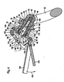
Im Gegensatz zu den voranstehenden Ausführungsbeispielen ist beim vierten Ausführungsbeispiel die Betätigungseinrichtung 140" als Drehantrieb ausgebildet und umfaßt als Betätigungselement 142' eine Zahnstange 242, welche mit einem Zahnritzel 244 einer Antriebswelle 246 in Eingriff steht, wobei die Antriebswelle 246 durch einen Drehantrieb 248 mit einem Freilauf 250 sowie einer Rasteinrichtung 252 antreibbar ist.In contrast to the preceding embodiments, in the fourth embodiment, the
Der Freilauf 250 wird gebildet durch eine Freilaufscheibe 254, die, wie in
Die Mitnehmernut 258 weist dabei, wie in
Ferner ist die Mitnehmerscheibe 260 an ihrer Außenumfangsseite mit einer Steuerkulisse 266 versehen, mit welcher ein Steuerstift 268 eines Rastkörpers 270 der Rasteinrichtung 252 verschiebbar ist, und zwar dahingehend, daß der Rastkörper 270 entgegen der Kraftwirkung einer Feder 272 in einer Ausrastrichtung 274 bewegbar ist.Further, the
Der Rastkörper 270 weist ferner eine Rastnase 276 auf, welche mit einer Rastausnehmung 278 in der Freilaufscheibe 254 dann in Eingriff bringbar ist, wenn die drehfest mit der Antriebswelle 246 gekoppelte Freilaufscheibe 254 in einer der aktiven Stellung des Antriebselements 112 entsprechenden Stellung steht. In dieser Stellung wird durch die Rastnase 276 des Rastkörpers 270 die Drehbewegung der Freilaufscheibe 254 blockiert und somit auch das Betätigungselement 142' gegen eine Bewegung in der Betätigungsrichtung 154 gesichert.The latching
Soll nun ein Verschieben des Antriebselements 112 von seiner aktiven Stellung in seine inaktive Stellung erfolgen, so erfolgt beispielsweise mittels eines Seilzuges 279 ein Drehen der Mitnehmerscheibe 260.If now a displacement of the
Da der Mitnehmer 256 in der durch den Rastkörper 270 fixierten Stellung der Freilaufscheibe 254 im Abstand von dem ersten Ende 262 der Mitnehmernut 258 steht (
Die Freilaufscheibe 254 wird dadurch mitgenommen, daß der Mitnehmer 256 an dem Ende 262 der Mitnehmernut 258 anliegt und mit der Mitnehmerscheibe 260 weitergedreht wird, wie in
Dadurch erfolgt auch eine entsprechende Drehung der Antriebswelle 246 und somit über das Ritzel 244 ein Einwirken auf die Zahnstange 242 im Sinne einer Verschiebung des Betätigungselements 142' in der Betätigungsrichtung 154 so lange, bis die Schwenkstellung des Anhängeelements 30 erreicht ist, wie in
In der inaktiven Stellung des Antriebselements 112 kann nun die Zugwirkung auf den Seilzug 278 entfallen und die Mitnehmerscheibe 260 hat die Möglichkeit, beaufschlagt durch eine Drehfeder 282 entgegengesetzt zur Drehrichtung 280 in ihre Ausgangsstellung zurückzudrehen, während die Freilaufscheibe 254 mit dem Mitnehmer 256 in einer der inaktiven Stellung des Antriebselements 112 und der Schwenkstellung des Anhängeelements 30 entsprechenden Stellung verharren kann, so lange bis das Anhängeelement 30 entweder in der Arbeitsstellung A oder der Ruhestellung R wieder in der Verschieberichtung 156 in die Fixierstellung verschoben wird und das Antriebselement 112 in der Fixierstellung in seine aktive Stellung übergeht. Hierbei kann dann der Mitnehmer 256 sich frei in die in
Claims (43)
- Trailer coupling for motor vehicles, comprising
a bearing element (20),
a towing element (30) pivotal in relation to the bearing element (20) between an operative position (A) and a rest position (R) about a pivot axis (52) of a pivot bearing (50) and displaceable at least in the operative position (A) between a pivoting position and a fixing position in the direction of the pivot axis (52), and a fixing device with which the towing element (30) is immovably fixable to the bearing element (20) at least in the operative position (A) and upon reaching the fixing position,
wherein the towing element (30) comprises a bearing body (70), wherein the bearing element (20) comprises a receiving body (60), with which the bearing body (70) enters into engagement at least in the fixing position, and in relation to which the bearing body (70) is movable between the pivoting position and the fixing position in a direction of displacement (156) and vice versa, wherein the bearing body (70) acts as bearing for the towing element (30) in both the pivoting position and the fixing position in relation to the receiving body (60), wherein the fixing device comprises a blocking device (90) blocking the bearing body (70) in relation to a movement in the direction of displacement (156) relative to the receiving body (60) and comprising at least one blocking body (88), which is arranged in the towing element (30), and which is movable in a manner acted upon by force from a release position in the direction of a blocking position, and at least one blocking surface (98), which is arranged on the bearing element (20), and with which the blocking body (88) enters into rear engagement in the blocking position, wherein the blocking device (90) comprises a blocking body drive (110), with which the blocking body (88) can be acted upon with a force moving the latter from the release position in the direction of the blocking position, wherein the blocking device (90) comprises an actuating device (140), which acts upon the blocking body drive (110), and with which it is possible to act upon a drive element (112) to counteract the action of the force of an elastic force accumulator (130), and wherein the actuating device (140) is arranged on the bearing element (20), and the blocking body drive (110) on the towing element (30). - Trailer coupling in accordance with the preceding claim, characterized in that the towing element (30) comprises a first end (34) carrying the coupling ball (36) and a second free end (82).
- Trailer coupling in accordance with claim 2, characterized in that the bearing body (70) is arranged on the towing element (30) between the ball neck (32) and the free end (82).
- Trailer coupling in accordance with any one of the preceding claims, characterized in that the receiving body (60) comprises a first opening (62) through which the bearing body (70), starting from the ball neck (32), engages the receiving body (60), and a second opening (104) located opposite the first opening (62).
- Trailer coupling in accordance with any one of the preceding claims, characterized in that the blocking body drive (110) comprises the drive element (112), with which the blocking body (88) is movable from the release position into the blocking position.
- Trailer coupling in accordance with claim 5, characterized in that the drive element (112) is acted upon by the elastic force accumulator (130).
- Trailer coupling in accordance with any one of the preceding claims, characterized in that the drive element (112) is arranged for displacement in a direction of activation (116) relative to the element (70) receiving the drive element (112).
- Trailer coupling in accordance with claim 7, characterized in that the drive element (112) comprises a drive connecting member (120) with a receiver (122) which the at least one blocking body (88) enters in the release position, and a displacement surface (124) with which the at least one blocking body (88) is movable from the release position into the blocking position.
- Trailer coupling in accordance with claim 8, characterized in that the displacement surface (124) is followed by a wedge surface (126) which acts upon the blocking body (88) in the blocking position for readjustment in the direction of movement (92).
- Trailer coupling in accordance with any one of the preceding claims, characterized in that the blocking device (90) holds positive-locking fixing elements (160, 162, 180, 182) of the fixing device in play-free abutment.
- Trailer coupling in accordance with any one of the preceding claims, characterized in that the blocking device (90) acts upon the positive-locking fixing elements (160, 162, 180, 182) for readjustment in a play-free manner.
- Trailer coupling in accordance with any one of the preceding claims, characterized in that the blocking device (90), in the blocking position of the at least one blocking body (88), on account of the latter cooperating with the blocking surface (98), acts with force upon the bearing body (70) in the direction of the fixing position.
- Trailer coupling in accordance with claim 12, characterized in that the blocking surface (98) extends at an incline to the direction of movement (92).
- Trailer coupling in accordance with any one of the preceding claims, characterized in that the at least one blocking body (88) and the blocking body drive (110) are arranged in the bearing body (70).
- Trailer coupling in accordance with claim 14, characterized in that in the bearing body (70), the at least one blocking body (88) is guided for movement between the release position and the blocking position in a direction of movement (92) transversely to the direction of displacement (156) thereof.
- Trailer coupling in accordance with any one of the preceding claims, characterized in that an actuating element (142) of the actuating device (140) projects beyond the free end (82) of the towing element (30).
- Trailer coupling in accordance with claim 16, characterized in that the actuating element (142) is arranged coaxially with the pivot axis (52).
- Trailer coupling in accordance with claim 17, characterized in that the actuating element (142) is mounted in the towing element (30) for rotation about the pivot axis (52).
- Trailer coupling in accordance with claim 18, characterized in that the actuating element (142) can be acted upon in the area thereof that projects beyond the free end (82) of the towing element (30) in the direction of the free end (82) of the towing element (30) in order to eliminate the force of the elastic force accumulator (130) acting upon the drive element (112).
- Trailer coupling in accordance with any one of the preceding claims, characterized in that with the blocking body (88) in release position, the towing element (30) is displaceable from the fixing position to the pivoting position with the actuating device (140).
- Trailer coupling in accordance with claim 20, characterized in that in the pivoting position, the towing element (30) is positionable in a defined manner in the direction of displacement (156) by means of the actuating device (140).
- Trailer coupling in accordance with any one of the preceding claims, characterized in that the actuating element (142) is coupled with a guide lever (146) of the actuating device (140).
- Trailer coupling in accordance with claim 22, characterized in that the guide lever (146) is pivotally mounted on the bearing element (20).
- Trailer coupling in accordance with any one of the preceding claims, characterized in that the actuating element (142') is constructed as a toothed rack (242) which meshes with a pinion (244) of the actuating device (140').
- Trailer coupling in accordance with any one of the preceding claims, characterized in that the actuating device (140', 140") is provided with a firee-wheel mechanism (240, 250) provided between the actuating element (142) and an acting element (232, 279).
- Trailer coupling in accordance with any one of the preceding claims, characterized in that in the pivoting position of the towing element (30), the receiving body (60) holds the at least one blocking body (88) in the release position.
- Trailer coupling in accordance with claim 26, characterized in that the receiving body (60) comprises a surface (68) which acts upon the at least one blocking body (88).
- Trailer coupling in accordance with any one of the preceding claims, characterized in that the at least one blocking body (88) is provided on the towing element (30) on a side of the bearing body (70), which is remote from the ball neck (32).
- Trailer coupling in accordance with claim 28, characterized in that the at least one blocking body (88) is arranged in lateral guide openings (84) of the towing element (30) in the direction of movement (92).
- Trailer coupling in accordance with claim 29, characterized in that the lateral guide openings (84) are arranged near the free end (82) of the towing element (30).
- Trailer coupling in accordance with any one of the preceding claims, characterized in that the drive element (112) is arranged in a recess (114) in the towing element (30).
- Trailer coupling in accordance with claim 31, characterized in that the recess (114) extends from an opening (118) provided at the free end (82) of the towing element (30) into the towing element (30).
- Trailer coupling in accordance with claim 31 or 32, characterized in that the recess (114) extends coaxially with the pivot axis (52).
- Trailer coupling in accordance with any one of claims 31 to 33, characterized in that the spring-elastic force accumulator (130) is supported on a bottom (132) of the recess (114), which is located opposite the opening (118).
- Trailer coupling in accordance with any one of the preceding claims, characterized in that the bearing element (20) comprises a receiving body (60) with an opening (62), starting from which a bearing body (70) of the towing element (30) engages with the receiving body (60), and in that the towing element (30) comprises a first positive-locking element (160), which, in the pivoting position of the towing element (30), is in disengagement from a second positive-locking element (162) provided on the receiving body (60), and which, at least in the operative position (A) can be brought into engagement with the second positive-locking element (162) at the end area of the receiving body (60) when the towing element (30) is displaced from the pivoting position to the fixing position.
- Trailer coupling in accordance with claim 35, characterized in that the second positive-locking element (162) is arranged on a side of the receiving body (60), which faces the ball neck (32).
- Trailer coupling in accordance with either one of claims 35 to 36, characterized in that the second positive-locking element (162) is arranged in a front end area of the receiving body (60).
- Trailer coupling in accordance with any one of claims 35 to 37, characterized in that the second positive-locking element (162) is integrally formed on the receiving body (60).
- Trailer coupling in accordance with any one of claims 35 to 38, characterized in that the first positive-locking element (160) is integrally formed on the towing element (30).
- Trailer coupling in accordance with any one of claims 35 to 39, characterized in that the first positive-locking element (160) is arranged in the area of a transition from the ball neck (32) to the bearing body (70).
- Trailer coupling in accordance with any one of claims 35 to 40, characterized in that the receiving body (60) comprises a third positive-locking element, with which the first positive-locking element (160) can be brought into engagement in the rest position (R).
- Trailer coupling in accordance with claim 41, characterized in that the third positive-locking element is identical in construction to the second positive-locking element (162).
- Trailer coupling in accordance with any one of the preceding claims, characterized in that the bearing body (60) comprises a guide track (202), on which a guide element (200) arranged on the towing element (30) rests when the towing element (30) is outside the operative position (A) and the rest position (R).
Applications Claiming Priority (2)
| Application Number | Priority Date | Filing Date | Title |
|---|---|---|---|
| DE102004004503.8A DE102004004503B4 (en) | 2004-01-22 | 2004-01-22 | hitch |
| DE102004004503 | 2004-01-22 |
Publications (3)
| Publication Number | Publication Date |
|---|---|
| EP1557298A1 EP1557298A1 (en) | 2005-07-27 |
| EP1557298B1 EP1557298B1 (en) | 2008-03-05 |
| EP1557298B2 true EP1557298B2 (en) | 2013-02-13 |
Family
ID=34625810
Family Applications (1)
| Application Number | Title | Priority Date | Filing Date |
|---|---|---|---|
| EP05000638A Active EP1557298B2 (en) | 2004-01-22 | 2005-01-14 | Trailer coupling |
Country Status (4)
| Country | Link |
|---|---|
| US (1) | US7216886B2 (en) |
| EP (1) | EP1557298B2 (en) |
| AT (1) | ATE388030T1 (en) |
| DE (2) | DE102004004503B4 (en) |
Families Citing this family (24)
| Publication number | Priority date | Publication date | Assignee | Title |
|---|---|---|---|---|
| DE102005032474A1 (en) | 2005-07-07 | 2007-01-11 | Oris Fahrzeugteile Hans Riehle Gmbh | hitch |
| DE102005053177A1 (en) * | 2005-11-03 | 2007-05-10 | Scambia Industrial Developments Aktiengesellschaft | actuator |
| DE102006035261A1 (en) * | 2006-07-29 | 2008-01-31 | Scambia Industrial Developments Aktiengesellschaft | Trailer coupling for vehicle, has rotating block device with rotating block body, which is movable in guidance direction with component in radial direction to swiveling axis and drive is actuator |
| DE102007003773A1 (en) * | 2007-01-19 | 2008-07-24 | Westfalia-Automotive Gmbh | Towing device for towing vehicle, has positive locking element movably supported at positive locking element bearing, and engaging in locking position in positive locking receiver at outer circumference of coupling arm |
| DE502007001779D1 (en) * | 2006-09-18 | 2009-12-03 | Westfalia Automotive Gmbh | Towing |
| DE102007003774A1 (en) * | 2007-01-19 | 2008-07-24 | Westfalia-Automotive Gmbh | Towing device with a locking device with actuating ring |
| DE102008030626A1 (en) * | 2008-06-23 | 2009-12-31 | Scambia Industrial Developments Aktiengesellschaft | Towing |
| DE102009015916A1 (en) * | 2009-03-25 | 2010-10-07 | Scambia Industrial Developments Aktiengesellschaft | Towing |
| US20100270774A1 (en) * | 2009-04-28 | 2010-10-28 | Midway Products Group, Inc. | Rotatable Trailer Hitch |
| DE102011053506A1 (en) | 2011-09-12 | 2013-03-14 | Scambia Holdings Cyprus Ltd. | Towing |
| DE102012008124A1 (en) † | 2012-04-25 | 2013-10-31 | Westfalia-Automotive Gmbh | Coupling arrangement for a rear carrier |
| DE102013007114A1 (en) * | 2013-04-21 | 2014-10-23 | Westfalia-Automotive Gmbh | Towing |
| NO20130966A1 (en) | 2013-07-11 | 2015-01-12 | Smart Patents As | System and procedure for automatically connecting a trailer to a vehicle |
| US10556473B2 (en) | 2013-07-11 | 2020-02-11 | Smart Patents As | System and method for connecting or disconnecting a trailer to a vehicle |
| DE102015100490A1 (en) * | 2015-01-14 | 2016-07-14 | Scambia Holdings Cyprus Limited | Towing |
| DE202015103207U1 (en) * | 2015-06-17 | 2016-09-20 | Westfalia-Automotive Gmbh | Trailer coupling with a receiving sleeve |
| NO20161592A1 (en) | 2016-10-04 | 2018-04-05 | Smart Patents As | Trailer for connecting to a vehicle, and trailer coupler |
| US11007831B2 (en) | 2017-09-01 | 2021-05-18 | B & W Custom Truck Beds, Inc. | Vehicle trailer hitch assembly |
| DE102018124518A1 (en) * | 2018-10-04 | 2020-04-09 | ACPS Automotive GmbH | Trailer coupling |
| SE544412C2 (en) * | 2019-03-12 | 2022-05-10 | Brink Towing Systems B V | Retractable towing hook arrangement |
| DE102019109398B4 (en) * | 2019-04-10 | 2021-05-27 | Dr. Ing. H.C. F. Porsche Aktiengesellschaft | trailer hitch |
| DE102020114231A1 (en) | 2020-05-27 | 2021-12-02 | ACPS Automotive GmbH | Towing hitch |
| NO346568B1 (en) * | 2020-05-29 | 2022-10-10 | Smart Patents As | Trailer coupling assembly and vehicle with trailer coupling assembly |
| CN215621229U (en) * | 2021-07-26 | 2022-01-25 | 浙江致优汽车科技有限公司 | Trailer coupler |
Family Cites Families (13)
| Publication number | Priority date | Publication date | Assignee | Title |
|---|---|---|---|---|
| DE29601156U1 (en) | 1996-01-24 | 1996-03-28 | Westfalia Werke Knoebel | Coupling ball carrier for vehicle trailer couplings |
| DE19612961A1 (en) * | 1996-04-01 | 1997-10-02 | Oris Fahrzeugteile Riehle H | Trailer coupling |
| DE19848487A1 (en) * | 1998-10-21 | 2000-05-04 | Oris Fahrzeugteile Riehle H | Trailer coupling |
| DE19902355A1 (en) * | 1999-01-21 | 2000-08-03 | Oris Fahrzeugteile Riehle H | Trailer coupling |
| EP1090782A3 (en) | 1999-10-04 | 2002-02-06 | PEKA-Fahrzeugbau GmbH & Co. KG | Trailer hitch for motor vehicles |
| DE10017013A1 (en) | 2000-04-05 | 2001-10-18 | Oris Fahrzeugteile Riehle H | Towing |
| DE10134318A1 (en) * | 2001-07-14 | 2003-01-23 | Fac Frank Abels Consult & Tech | trailer hitch |
| DE10144254A1 (en) | 2001-09-03 | 2003-04-03 | Oris Fahrzeugteile Riehle H | Towing |
| DE20120530U1 (en) | 2001-12-19 | 2002-05-23 | Westfalia Automotive Gmbh & Co | Trailer device for motor vehicles |
| DE10320302A1 (en) | 2003-05-07 | 2004-12-09 | Westfalia-Automotive Gmbh & Co. Kg | Trailer coupling for motor vehicles |
| US6860503B2 (en) | 2002-11-13 | 2005-03-01 | Westfalia-Automotive Gmbh & Co. Kg | Retractile motor-vehicle trailer hitch |
| DE10252722B3 (en) * | 2002-11-13 | 2004-02-19 | Westfalia-Automotive Gmbh & Co. Kg | Trailer coupling for motor vehicles has tow bar bearing head with centrally integrated locking mechanism, located on hollow shaft fastened to mounted flange |
| DE10336445B4 (en) * | 2003-08-08 | 2006-04-20 | Westfalia-Automotive Gmbh & Co. Kg | Towbar for motor vehicles |
-
2004
- 2004-01-22 DE DE102004004503.8A patent/DE102004004503B4/en not_active Expired - Lifetime
-
2005
- 2005-01-14 EP EP05000638A patent/EP1557298B2/en active Active
- 2005-01-14 AT AT05000638T patent/ATE388030T1/en not_active IP Right Cessation
- 2005-01-14 DE DE502005003040T patent/DE502005003040D1/en active Active
- 2005-01-18 US US11/039,081 patent/US7216886B2/en active Active
Also Published As
| Publication number | Publication date |
|---|---|
| DE102004004503B4 (en) | 2022-01-20 |
| EP1557298B1 (en) | 2008-03-05 |
| DE502005003040D1 (en) | 2008-04-17 |
| US7216886B2 (en) | 2007-05-15 |
| EP1557298A1 (en) | 2005-07-27 |
| DE102004004503A1 (en) | 2005-08-18 |
| US20050167945A1 (en) | 2005-08-04 |
| ATE388030T1 (en) | 2008-03-15 |
Similar Documents
| Publication | Publication Date | Title |
|---|---|---|
| EP1557298B2 (en) | Trailer coupling | |
| EP2261066B1 (en) | Trailer device | |
| EP1182062B2 (en) | Trailer coupling | |
| EP1621386B1 (en) | Wind stop device | |
| EP1557300B2 (en) | Trailer hitch | |
| EP2567835B2 (en) | Tow bar | |
| EP2792514B1 (en) | Trailer coupling | |
| DE102020111468A1 (en) | Trailer coupling | |
| EP1790504B2 (en) | Drive unit for a trailer coupling | |
| EP2792513A1 (en) | Trailer coupling | |
| DE102005047379A1 (en) | Draw bar for motor vehicle, has movable adjusting body provided at coupling carrier for causing relative movement of positive lock structures, where relative movement of positive locking structures takes place transverse to rotational axis | |
| EP1197357A1 (en) | Trailer coupling | |
| EP2181868B1 (en) | Tow bar | |
| EP2799261A1 (en) | Trailer coupling | |
| EP0913276B1 (en) | Towing device | |
| EP2796303B1 (en) | Trailer coupling | |
| EP2796305B1 (en) | Trailer coupling | |
| EP3441243B2 (en) | Motor-driven pivotable trailer coupling | |
| EP2796304A1 (en) | Tow bar | |
| DE10209811A1 (en) | Convertible, fitted with mechanism for convenient separate or simultaneous moving of roll bar and soft top | |
| DE10125781A1 (en) | hitch |
Legal Events
| Date | Code | Title | Description |
|---|---|---|---|
| PUAI | Public reference made under article 153(3) epc to a published international application that has entered the european phase |
Free format text: ORIGINAL CODE: 0009012 |
|
| AK | Designated contracting states |
Kind code of ref document: A1 Designated state(s): AT BE BG CH CY CZ DE DK EE ES FI FR GB GR HU IE IS IT LI LT LU MC NL PL PT RO SE SI SK TR |
|
| AX | Request for extension of the european patent |
Extension state: AL BA HR LV MK YU |
|
| 17P | Request for examination filed |
Effective date: 20050928 |
|
| AKX | Designation fees paid |
Designated state(s): AT BE BG CH CY CZ DE DK EE ES FI FR GB GR HU IE IS IT LI LT LU MC NL PL PT RO SE SI SK TR |
|
| 17Q | First examination report despatched |
Effective date: 20060720 |
|
| RAP1 | Party data changed (applicant data changed or rights of an application transferred) |
Owner name: SCAMBIA INDUSTRIAL DEVELOPMENTS AKTIENGESELLSCHAFT |
|
| GRAP | Despatch of communication of intention to grant a patent |
Free format text: ORIGINAL CODE: EPIDOSNIGR1 |
|
| GRAS | Grant fee paid |
Free format text: ORIGINAL CODE: EPIDOSNIGR3 |
|
| GRAA | (expected) grant |
Free format text: ORIGINAL CODE: 0009210 |
|
| AK | Designated contracting states |
Kind code of ref document: B1 Designated state(s): AT BE BG CH CY CZ DE DK EE ES FI FR GB GR HU IE IS IT LI LT LU MC NL PL PT RO SE SI SK TR |
|
| REG | Reference to a national code |
Ref country code: GB Ref legal event code: FG4D Free format text: NOT ENGLISH |
|
| REG | Reference to a national code |
Ref country code: CH Ref legal event code: EP |
|
| REG | Reference to a national code |
Ref country code: IE Ref legal event code: FG4D Free format text: LANGUAGE OF EP DOCUMENT: GERMAN |
|
| REF | Corresponds to: |
Ref document number: 502005003040 Country of ref document: DE Date of ref document: 20080417 Kind code of ref document: P |
|
| PG25 | Lapsed in a contracting state [announced via postgrant information from national office to epo] |
Ref country code: FI Free format text: LAPSE BECAUSE OF FAILURE TO SUBMIT A TRANSLATION OF THE DESCRIPTION OR TO PAY THE FEE WITHIN THE PRESCRIBED TIME-LIMIT Effective date: 20080305 Ref country code: ES Free format text: LAPSE BECAUSE OF FAILURE TO SUBMIT A TRANSLATION OF THE DESCRIPTION OR TO PAY THE FEE WITHIN THE PRESCRIBED TIME-LIMIT Effective date: 20080616 |
|
| PG25 | Lapsed in a contracting state [announced via postgrant information from national office to epo] |
Ref country code: SI Free format text: LAPSE BECAUSE OF FAILURE TO SUBMIT A TRANSLATION OF THE DESCRIPTION OR TO PAY THE FEE WITHIN THE PRESCRIBED TIME-LIMIT Effective date: 20080305 Ref country code: PL Free format text: LAPSE BECAUSE OF FAILURE TO SUBMIT A TRANSLATION OF THE DESCRIPTION OR TO PAY THE FEE WITHIN THE PRESCRIBED TIME-LIMIT Effective date: 20080305 |
|
| REG | Reference to a national code |
Ref country code: IE Ref legal event code: FD4D |
|
| PG25 | Lapsed in a contracting state [announced via postgrant information from national office to epo] |
Ref country code: PT Free format text: LAPSE BECAUSE OF FAILURE TO SUBMIT A TRANSLATION OF THE DESCRIPTION OR TO PAY THE FEE WITHIN THE PRESCRIBED TIME-LIMIT Effective date: 20080805 Ref country code: CZ Free format text: LAPSE BECAUSE OF FAILURE TO SUBMIT A TRANSLATION OF THE DESCRIPTION OR TO PAY THE FEE WITHIN THE PRESCRIBED TIME-LIMIT Effective date: 20080305 Ref country code: SK Free format text: LAPSE BECAUSE OF FAILURE TO SUBMIT A TRANSLATION OF THE DESCRIPTION OR TO PAY THE FEE WITHIN THE PRESCRIBED TIME-LIMIT Effective date: 20080305 Ref country code: SE Free format text: LAPSE BECAUSE OF FAILURE TO SUBMIT A TRANSLATION OF THE DESCRIPTION OR TO PAY THE FEE WITHIN THE PRESCRIBED TIME-LIMIT Effective date: 20080605 |
|
| PG25 | Lapsed in a contracting state [announced via postgrant information from national office to epo] |
Ref country code: RO Free format text: LAPSE BECAUSE OF FAILURE TO SUBMIT A TRANSLATION OF THE DESCRIPTION OR TO PAY THE FEE WITHIN THE PRESCRIBED TIME-LIMIT Effective date: 20080305 |
|
| PLBI | Opposition filed |
Free format text: ORIGINAL CODE: 0009260 |
|
| EN | Fr: translation not filed | ||
| PG25 | Lapsed in a contracting state [announced via postgrant information from national office to epo] |
Ref country code: IS Free format text: LAPSE BECAUSE OF FAILURE TO SUBMIT A TRANSLATION OF THE DESCRIPTION OR TO PAY THE FEE WITHIN THE PRESCRIBED TIME-LIMIT Effective date: 20080705 |
|
| 26 | Opposition filed |
Opponent name: WESTFALIA-AUTOMOTIVE GMBH Effective date: 20081203 |
|
| PLAX | Notice of opposition and request to file observation + time limit sent |
Free format text: ORIGINAL CODE: EPIDOSNOBS2 |
|
| PG25 | Lapsed in a contracting state [announced via postgrant information from national office to epo] |
Ref country code: DK Free format text: LAPSE BECAUSE OF FAILURE TO SUBMIT A TRANSLATION OF THE DESCRIPTION OR TO PAY THE FEE WITHIN THE PRESCRIBED TIME-LIMIT Effective date: 20080305 Ref country code: IE Free format text: LAPSE BECAUSE OF FAILURE TO SUBMIT A TRANSLATION OF THE DESCRIPTION OR TO PAY THE FEE WITHIN THE PRESCRIBED TIME-LIMIT Effective date: 20080305 Ref country code: LT Free format text: LAPSE BECAUSE OF FAILURE TO SUBMIT A TRANSLATION OF THE DESCRIPTION OR TO PAY THE FEE WITHIN THE PRESCRIBED TIME-LIMIT Effective date: 20080305 |
|
| NLR1 | Nl: opposition has been filed with the epo |
Opponent name: WESTFALIA-AUTOMOTIVE GMBH |
|
| PG25 | Lapsed in a contracting state [announced via postgrant information from national office to epo] |
Ref country code: EE Free format text: LAPSE BECAUSE OF FAILURE TO SUBMIT A TRANSLATION OF THE DESCRIPTION OR TO PAY THE FEE WITHIN THE PRESCRIBED TIME-LIMIT Effective date: 20080305 Ref country code: FR Free format text: LAPSE BECAUSE OF FAILURE TO SUBMIT A TRANSLATION OF THE DESCRIPTION OR TO PAY THE FEE WITHIN THE PRESCRIBED TIME-LIMIT Effective date: 20081226 Ref country code: BG Free format text: LAPSE BECAUSE OF FAILURE TO SUBMIT A TRANSLATION OF THE DESCRIPTION OR TO PAY THE FEE WITHIN THE PRESCRIBED TIME-LIMIT Effective date: 20080605 |
|
| PLAF | Information modified related to communication of a notice of opposition and request to file observations + time limit |
Free format text: ORIGINAL CODE: EPIDOSCOBS2 |
|
| PLBB | Reply of patent proprietor to notice(s) of opposition received |
Free format text: ORIGINAL CODE: EPIDOSNOBS3 |
|
| PG25 | Lapsed in a contracting state [announced via postgrant information from national office to epo] |
Ref country code: IT Free format text: LAPSE BECAUSE OF FAILURE TO SUBMIT A TRANSLATION OF THE DESCRIPTION OR TO PAY THE FEE WITHIN THE PRESCRIBED TIME-LIMIT Effective date: 20080305 Ref country code: MC Free format text: LAPSE BECAUSE OF NON-PAYMENT OF DUE FEES Effective date: 20090131 |
|
| REG | Reference to a national code |
Ref country code: CH Ref legal event code: PL |
|
| GBPC | Gb: european patent ceased through non-payment of renewal fee |
Effective date: 20090114 |
|
| PG25 | Lapsed in a contracting state [announced via postgrant information from national office to epo] |
Ref country code: CY Free format text: LAPSE BECAUSE OF FAILURE TO SUBMIT A TRANSLATION OF THE DESCRIPTION OR TO PAY THE FEE WITHIN THE PRESCRIBED TIME-LIMIT Effective date: 20080305 |
|
| PG25 | Lapsed in a contracting state [announced via postgrant information from national office to epo] |
Ref country code: CH Free format text: LAPSE BECAUSE OF NON-PAYMENT OF DUE FEES Effective date: 20090131 Ref country code: LI Free format text: LAPSE BECAUSE OF NON-PAYMENT OF DUE FEES Effective date: 20090131 |
|
| PG25 | Lapsed in a contracting state [announced via postgrant information from national office to epo] |
Ref country code: GB Free format text: LAPSE BECAUSE OF NON-PAYMENT OF DUE FEES Effective date: 20090114 |
|
| PG25 | Lapsed in a contracting state [announced via postgrant information from national office to epo] |
Ref country code: BE Free format text: LAPSE BECAUSE OF NON-PAYMENT OF DUE FEES Effective date: 20090131 |
|
| PG25 | Lapsed in a contracting state [announced via postgrant information from national office to epo] |
Ref country code: AT Free format text: LAPSE BECAUSE OF NON-PAYMENT OF DUE FEES Effective date: 20090114 |
|
| PLCK | Communication despatched that opposition was rejected |
Free format text: ORIGINAL CODE: EPIDOSNREJ1 |
|
| PG25 | Lapsed in a contracting state [announced via postgrant information from national office to epo] |
Ref country code: GR Free format text: LAPSE BECAUSE OF FAILURE TO SUBMIT A TRANSLATION OF THE DESCRIPTION OR TO PAY THE FEE WITHIN THE PRESCRIBED TIME-LIMIT Effective date: 20080606 |
|
| APBM | Appeal reference recorded |
Free format text: ORIGINAL CODE: EPIDOSNREFNO |
|
| APBP | Date of receipt of notice of appeal recorded |
Free format text: ORIGINAL CODE: EPIDOSNNOA2O |
|
| APAH | Appeal reference modified |
Free format text: ORIGINAL CODE: EPIDOSCREFNO |
|
| APBQ | Date of receipt of statement of grounds of appeal recorded |
Free format text: ORIGINAL CODE: EPIDOSNNOA3O |
|
| PG25 | Lapsed in a contracting state [announced via postgrant information from national office to epo] |
Ref country code: LU Free format text: LAPSE BECAUSE OF NON-PAYMENT OF DUE FEES Effective date: 20090114 |
|
| PG25 | Lapsed in a contracting state [announced via postgrant information from national office to epo] |
Ref country code: HU Free format text: LAPSE BECAUSE OF FAILURE TO SUBMIT A TRANSLATION OF THE DESCRIPTION OR TO PAY THE FEE WITHIN THE PRESCRIBED TIME-LIMIT Effective date: 20080906 |
|
| PG25 | Lapsed in a contracting state [announced via postgrant information from national office to epo] |
Ref country code: TR Free format text: LAPSE BECAUSE OF FAILURE TO SUBMIT A TRANSLATION OF THE DESCRIPTION OR TO PAY THE FEE WITHIN THE PRESCRIBED TIME-LIMIT Effective date: 20080305 |
|
| APBU | Appeal procedure closed |
Free format text: ORIGINAL CODE: EPIDOSNNOA9O |
|
| PUAH | Patent maintained in amended form |
Free format text: ORIGINAL CODE: 0009272 |
|
| STAA | Information on the status of an ep patent application or granted ep patent |
Free format text: STATUS: PATENT MAINTAINED AS AMENDED |
|
| RAP2 | Party data changed (patent owner data changed or rights of a patent transferred) |
Owner name: SCAMBIA INDUSTRIAL DEVELOPMENTS AKTIENGESELLSCHAFT |
|
| RAP2 | Party data changed (patent owner data changed or rights of a patent transferred) |
Owner name: SCAMBIA INDUSTRIAL DEVELOPMENTS AKTIENGESELLSCHAFT |
|
| 27A | Patent maintained in amended form |
Effective date: 20130213 |
|
| AK | Designated contracting states |
Kind code of ref document: B2 Designated state(s): AT BE BG CH CY CZ DE DK EE ES FI FR GB GR HU IE IS IT LI LT LU MC NL PL PT RO SE SI SK TR |
|
| REG | Reference to a national code |
Ref country code: DE Ref legal event code: R102 Ref document number: 502005003040 Country of ref document: DE Effective date: 20130213 |
|
| REG | Reference to a national code |
Ref country code: NL Ref legal event code: T3 |
|
| REG | Reference to a national code |
Ref country code: NL Ref legal event code: SD Effective date: 20150312 |
|
| REG | Reference to a national code |
Ref country code: DE Ref legal event code: R082 Ref document number: 502005003040 Country of ref document: DE Representative=s name: HOEGER, STELLRECHT & PARTNER PATENTANWAELTE, DE |
|
| REG | Reference to a national code |
Ref country code: DE Ref legal event code: R082 Ref document number: 502005003040 Country of ref document: DE Representative=s name: HOEGER, STELLRECHT & PARTNER PATENTANWAELTE, DE Effective date: 20150407 Ref country code: DE Ref legal event code: R081 Ref document number: 502005003040 Country of ref document: DE Owner name: SCAMBIA HOLDINGS CYPRUS LTD., CY Free format text: FORMER OWNER: SCAMBIA INDUSTRIAL DEVELOPMENTS AKTIENGESELLSCHAFT, SCHAAN, LI Effective date: 20150407 Ref country code: DE Ref legal event code: R082 Ref document number: 502005003040 Country of ref document: DE Representative=s name: HOEGER, STELLRECHT & PARTNER PATENTANWAELTE MB, DE Effective date: 20150407 Ref country code: DE Ref legal event code: R081 Ref document number: 502005003040 Country of ref document: DE Owner name: BOSAL ACPS HOLDING 2 B.V., NL Free format text: FORMER OWNER: SCAMBIA INDUSTRIAL DEVELOPMENTS AKTIENGESELLSCHAFT, SCHAAN, LI Effective date: 20150407 |
|
| REG | Reference to a national code |
Ref country code: DE Ref legal event code: R082 Ref document number: 502005003040 Country of ref document: DE Representative=s name: HOEGER, STELLRECHT & PARTNER PATENTANWAELTE MB, DE |
|
| REG | Reference to a national code |
Ref country code: DE Ref legal event code: R081 Ref document number: 502005003040 Country of ref document: DE Owner name: ACPS AUTOMOTIVE GMBH, DE Free format text: FORMER OWNER: SCAMBIA HOLDINGS CYPRUS LTD., LIMASSOL, CY Ref country code: DE Ref legal event code: R082 Ref document number: 502005003040 Country of ref document: DE Representative=s name: HOEGER, STELLRECHT & PARTNER PATENTANWAELTE MB, DE Ref country code: DE Ref legal event code: R081 Ref document number: 502005003040 Country of ref document: DE Owner name: BOSAL ACPS HOLDING 2 B.V., NL Free format text: FORMER OWNER: SCAMBIA HOLDINGS CYPRUS LTD., LIMASSOL, CY |
|
| REG | Reference to a national code |
Ref country code: NL Ref legal event code: PD Owner name: BOSAL ACPS HOLDING 2 B.V.; NL Free format text: DETAILS ASSIGNMENT: CHANGE OF OWNER(S), ASSIGNMENT; FORMER OWNER NAME: SCAMBIA HOLDINGS CYPRUS LIMITED Effective date: 20180710 |
|
| REG | Reference to a national code |
Ref country code: DE Ref legal event code: R082 Ref document number: 502005003040 Country of ref document: DE Representative=s name: HOEGER, STELLRECHT & PARTNER PATENTANWAELTE MB, DE Ref country code: DE Ref legal event code: R081 Ref document number: 502005003040 Country of ref document: DE Owner name: ACPS AUTOMOTIVE GMBH, DE Free format text: FORMER OWNER: BOSAL ACPS HOLDING 2 B.V., VIANEN, NL |
|
| REG | Reference to a national code |
Ref country code: DE Ref legal event code: R082 Ref document number: 502005003040 Country of ref document: DE Representative=s name: HOEGER, STELLRECHT & PARTNER PATENTANWAELTE MB, DE |
|
| REG | Reference to a national code |
Ref country code: NL Ref legal event code: PD Owner name: ACPS AUTOMOTIVE GMBH; DE Free format text: DETAILS ASSIGNMENT: CHANGE OF OWNER(S), ASSIGNMENT; FORMER OWNER NAME: SCAMBIA HOLDINGS CYPRUS LIMITED Effective date: 20210907 Ref country code: NL Ref legal event code: HC Owner name: ACPS AUTOMOTIVE HOLDING 2 B.V.; NL Free format text: DETAILS ASSIGNMENT: CHANGE OF OWNER(S), CHANGE OF OWNER(S) NAME; FORMER OWNER NAME: BOSAL ACPS HOLDING 2 B.V. Effective date: 20210907 |
|
| REG | Reference to a national code |
Ref country code: DE Ref legal event code: R081 Ref document number: 502005003040 Country of ref document: DE Owner name: ACPS AUTOMOTIVE GMBH, DE Free format text: FORMER OWNER: ACPS AUTOMOTIVE GMBH, 71706 MARKGROENINGEN, DE |
|
| PGFP | Annual fee paid to national office [announced via postgrant information from national office to epo] |
Ref country code: DE Payment date: 20230123 Year of fee payment: 19 |
|
| P01 | Opt-out of the competence of the unified patent court (upc) registered |
Effective date: 20230517 |
|
| PGFP | Annual fee paid to national office [announced via postgrant information from national office to epo] |
Ref country code: NL Payment date: 20230119 Year of fee payment: 19 |
|
| PGFP | Annual fee paid to national office [announced via postgrant information from national office to epo] |
Ref country code: NL Payment date: 20240119 Year of fee payment: 20 |