EP3441243B2 - Attelage de remorque pouvant pivoter de manière motorisée - Google Patents
Attelage de remorque pouvant pivoter de manière motorisée Download PDFInfo
- Publication number
- EP3441243B2 EP3441243B2 EP18187661.6A EP18187661A EP3441243B2 EP 3441243 B2 EP3441243 B2 EP 3441243B2 EP 18187661 A EP18187661 A EP 18187661A EP 3441243 B2 EP3441243 B2 EP 3441243B2
- Authority
- EP
- European Patent Office
- Prior art keywords
- coupling arm
- locking element
- drive
- arm
- locking
- Prior art date
- Legal status (The legal status is an assumption and is not a legal conclusion. Google has not performed a legal analysis and makes no representation as to the accuracy of the status listed.)
- Active
Links
Images


Classifications
-
- B—PERFORMING OPERATIONS; TRANSPORTING
- B60—VEHICLES IN GENERAL
- B60D—VEHICLE CONNECTIONS
- B60D1/00—Traction couplings; Hitches; Draw-gear; Towing devices
- B60D1/48—Traction couplings; Hitches; Draw-gear; Towing devices characterised by the mounting
- B60D1/54—Traction couplings; Hitches; Draw-gear; Towing devices characterised by the mounting collapsible or retractable when not in use, e.g. hide-away hitches
-
- B—PERFORMING OPERATIONS; TRANSPORTING
- B60—VEHICLES IN GENERAL
- B60D—VEHICLE CONNECTIONS
- B60D1/00—Traction couplings; Hitches; Draw-gear; Towing devices
- B60D1/01—Traction couplings or hitches characterised by their type
- B60D1/06—Ball-and-socket hitches
-
- B—PERFORMING OPERATIONS; TRANSPORTING
- B60—VEHICLES IN GENERAL
- B60D—VEHICLE CONNECTIONS
- B60D1/00—Traction couplings; Hitches; Draw-gear; Towing devices
- B60D1/58—Auxiliary devices
- B60D1/62—Auxiliary devices involving supply lines, electric circuits or the like
Definitions
- the present invention relates to a trailer coupling for vehicles with a movable coupling arm according to the preamble of patent claim 1.
- EP 1 142 732 A2 describes a trailer hitch with a pivot bearing body fixed to the vehicle, on which a pivot element is mounted pivotably about a pivot axis, a ball neck which extends from the pivot element and carries a coupling ball on its end facing away from the pivot element, and a locking device for positively locking the pivot element in relation to the swivel bearing body.
- the DE 198 58 978 A1 discloses a trailer hitch for motor vehicles, wherein a ball bar is fixed in a working position via a pretensioning device.
- Such motor-pivoted trailer hitches are known per se and are used to move parts of a trailer hitch mounted on a vehicle into a hidden position when not in use, for example by moving the coupling arm relative to the vehicle body or other vehicle parts and in the rest position, which the represents a position concealed from view, is accordingly arranged behind vehicle parts or body parts of the vehicle, such as a bumper or a rear bumper.
- the coupling arm can move so that the coupling arm becomes loose and the working position is at least partially canceled or released.
- the object of the present invention is to specify a trailer coupling for vehicles with a movable coupling arm, which can be moved between a working position and a rest position with at least one drive, which overcomes the disadvantages of the prior art, in particular re-clocking of the drive reduced or completely avoided in order to maintain the working position.
- the locking element on the one hand allows locking in the working position of the coupling arm and at the same time at least reduces the application of force in at least one drive, as far as forces acting on the coupling arm in the working position.
- This at least significantly reduces the re-clocking of the at least one drive, since the locking element holds the coupling arm in the working position or presses it into the working position and at the same time at least reduces the introduction of force into at least one drive, thereby preventing the coupling arm from being released or knocked loose, which is associated with re-clocking the at least one drive would have to be compensated, prevented.
- the locking element diverts at least part of the forces introduced into the device via the coupling arm and thus reduces the introduction of force to the at least one drive.
- the locking element holds the coupling arm in the working position in such a way that at least one drive is kept free of force when force is applied to the coupling arm in the working position. This makes it possible for the locking element to interrupt the power transmission between the coupling arm on the one hand and the at least one drive on the other hand. In addition, the locking element keeps the coupling arm in the working position, despite the interrupted power transmission between the at least one drive and the coupling arm.
- the locking element absorbs the forces that arise when a force is applied to the coupling arm and are suitable for releasing the coupling arm from the working position or for reducing the locking of the coupling arm in the working position and are thus transferred or diverted to the structure of the trailer coupling that a force is not applied to at least one drive.
- the locking element also acts as a "force diversion” or “force bypass” which ensures that the coupling arm is locked in the working position without the need for reclocking of the at least one drive.
- the locking element is designed as part of an actuating mechanism driven by a drive.
- the locking element is thus designed as a dynamic or movable element of the trailer hitch. This means that the locking element is moved completely or as a whole and together with other components of the actuating mechanism in relation to the trailer hitch when the coupling arm is transferred between the working position and the rest position.
- the locking element is not fixedly articulated in the trailer hitch, in particular a housing part, but can be moved together with the actuating mechanism.
- the trailer hitch according to the invention is advantageously made more compact. Because an actuating mechanism driven by at least one drive for transferring the coupling arm between the working position and the rest position is necessarily provided in a generic trailer hitch.
- an actuating mechanism driven by at least one drive for transferring the coupling arm between the working position and the rest position is necessarily provided in a generic trailer hitch.
- a separate locking element can advantageously be saved in addition to the driven adjusting mechanism.
- the trailer hitch according to the invention requires little installation space and could also be manufactured more cheaply.
- the locking element is set up in a release position for power transmission between at least one drive and the coupling arm.
- a power transmission can be achieved in particular in that the locking element is designed as part of a driven actuating mechanism.
- the release position of the locking element does not have to be a single position and/or orientation of the locking element relative to the coupling arm or relative to the trailer hitch. Rather, especially when the locking element is designed as a dynamic part of a driven actuating mechanism, it can be provided that each position of the locking element apart from the position that locks the coupling arm in the working position can be assumed to be a release position of the locking element.
- a further advantageous embodiment of the trailer hitch provides that the locking element has at least one joint mount.
- the locking element is transferred into the locking position by a rotary and/or tilting movement about a corresponding joint, in which the locking element locks the coupling arm in the working position.
- the locking of the coupling arm in the working position can be released in an equally safe and simple manner.
- the locking element is connected at a first end via a joint to a pivot bearing part of the coupling arm.
- rotary bearing parts are used in trailer hitches of this type in order to be able to superimpose different movements of the coupling arm when transferring between the rest position and the working position.
- such rotary bearing parts at least also allow the coupling arm to rotate about an axis of rotation.
- the coupling arm can have a receiving section which is rotatably mounted on a bearing surface of the rotary bearing part.
- connection between the pivot bearing part and the locking element enables the locking element to be integrated into an actuating mechanism.
- the connection can be achieved, for example, via the above-described joint receptacle of the locking element on the one hand and a joint formed by the pivot bearing part on the other hand, for example in the form of a joint bolt.
- an embodiment of the trailer hitch according to the invention provides that the locking element can be moved between a locking position and a release position by rotating it relative to the rotary bearing part.
- the locking element comes into contact with a support stop in the locking position. It is particularly advantageous if the locking element comes to rest against a support stop with a second end of the locking element. Since the If the locking position of the locking element is also characterized in that the coupling arm is held in the working position in the locking position of the locking element, the advantageous embodiment can also be understood in such a way that the locking element is designed in such a way that it, in particular with a second end, rests against a support stop comes when the locking element holds the coupling arm in the working position.
- the support stop can be formed in a housing part of the trailer coupling and to be connected to the housing part in such a way that when the locking element is in the locking position, a force is applied to the coupling arm via the locking element and the support stop into the housing part of the trailer coupling, wherein the at least one drive is at least relieved or kept completely free of force.
- the locking position there can be a force fit or friction fit between the support stop and the locking element.
- the locking element, in particular the second end of the locking element, and the support stop are designed and aligned with one another in the locking position such that a force acting on the coupling arm increases the frictional connection between the support stop and the locking element or at least leaves it unchanged. This achieves self-locking of the locking element, which ensures that the locking element does not leave the locking position, in particular when force is applied to the coupling arm in the working position of the coupling arm, but rather is further urged into the locking position.
- the asymmetrical shape can be implemented, for example, by a circular rounding which is arranged eccentrically with respect to a longitudinal axis of symmetry of the locking element. In this way it can be achieved that the bracing force between the locking element and a support stop in the locking position of the locking element is increased and, in addition, a compensation for wear and tolerances is formed. If it is not the second end but another part of the locking element that comes into contact with a support stop or a device part with the same effect, that part of the locking element can also have the asymmetrical shape, in particular the asymmetrical rounding.
- the trailer hitch comprises at least one guide means for guiding the locking element, in particular the second end of the locking element, in the release position of the locking element or outside of the locking position of the locking element.
- the at least one guide means can ensure that the locking element is guided in the release position during the transfer between the rest position and the working position, which means that unwanted movements of the locking element, such as unwanted twisting, tilting or transverse positioning of the locking element in the release position is prevented.
- At least one guide element for guiding the locking element is particularly advantageous when the locking element is also part of an actuating mechanism and/or is set up in the release position for power transmission between at least one drive and the coupling arm.
- the locking element is designed as an arm of a triple joint.
- the provision of a triple joint or an articulated arm with three joints including the locking element has the advantage that the locking element can be designed as part of the adjusting mechanism and that other arms of the triple joint can also be designed as part of the adjusting mechanism on the one hand and on the other hand can serve as a drive lever for the locking element in order to move the locking element not only, but also between the release position and the locking position, in particular to twist it.
- the corresponding articulated arm or the triple joint can therefore comprise two arms and three joints, with at least one arm being formed by the locking element.
- the second arm is preferably formed by at least one drive lever.
- the triple joint can be particularly advantageous for the triple joint to be designed in such a way that it experiences maximum stretching when the coupling arm is in the rest position, with complete stretching being prevented.
- the locking element and the at least one drive lever enclose an angle that is not equal to 180° in every position. This prevents, in a particularly advantageous manner, that the triple joint is transferred into a dead center position when the coupling arm is transferred between the working position and the rest position.
- the triple joint is designed in such a way that it undergoes a maximum deflection in the working position of the coupling arm. In a particularly advantageous manner, this ensures that the locking position of the locking element can be established easily and securely, and likewise that the locking element can be transferred securely and easily between the locking position and the release position.
- a further, particularly preferred embodiment of the trailer coupling provides at least two guide means which determine or limit the relative position of the arms of the triple joint to one another when the coupling arm is transferred between the rest position and the working position.
- the guide means can each form a guide face or guide surface.
- the guide surfaces can face each other so that a guide channel is formed between the guide surfaces.
- the locking element and/or other parts of the adjusting mechanism or the triple joint can come to rest on the guide surfaces and slide along during the transfer of the coupling arm between the rest position and the working position. This ensures precise and repeatable movement of at least the locking element.
- a rotary bearing part of the coupling arm is rigidly connected to a tilting arm. This advantageously enables the pivot bearing part and thus also the coupling arm to be able to perform a tilting movement, which can be superimposed with other movements during the transfer of the coupling arm between the working position and the rest position.
- the tilting arm can be rigidly connected at an end facing away from the rotary bearing part to an axle which is guided in a connecting link, in particular via at least one axle projection.
- the axle projection serves as a sliding block that ensures that the axle is guided in or through the link.
- the link and the at least one axis projection are designed in relation to one another such that in a certain part or section of the link, the axis connected to the tilting arm is released and can therefore be rotated at least by a certain angle, whereas the link and the at least one axle projection in other sections of the connecting link are matched to one another in such a way that the rotation of the axle is prevented.
- the pivot bearing part can be tilted about the tilting arm in a particularly advantageous manner without its own or an additional drive, but rather as a result of another movement of the coupling arm and in particular the pivot bearing part of the coupling arm caused by the at least one drive.
- the connecting link and in particular the axle projection is designed or are designed in such a way that in the working position of the coupling arm, in particular in the locking position of the locking element, rotation of the axis connected to the tilting arm is prevented. This also ensures that when a force is applied to the coupling arm in the working position of the coupling arm, an effective reduction or prevention of the application of force to at least one drive of the trailer hitch can take place.
- the connecting link has a translation section which, in particular in relation to an axial projection of the axle, is designed in such a way that when the coupling arm is transferred from the working position to the rest position, a displacement or Translation of the axis takes place along the backdrop. In this way it can also be achieved that during the transfer of the coupling arm from the working position to the rest position, first a translation of the coupling arm is brought about, which can possibly be superimposed with a rotation of the coupling arm.
- the connecting link has a rotating section which, in particular taking into account the at least one axial projection, is designed in such a way that when the coupling arm is transferred from the working position to the rest position in order to reach the rest position, a rotation of the axis takes place.
- the rotation of the axis in the rotating section of the gate leads to a tilting of the tilting arm and thus to a corresponding tilting of the pivot bearing part of the coupling arm and the coupling arm.
- Such a movement to reach the rest position of the coupling arm has the advantage that the coupling arm can be arranged in a particularly space-saving manner in the rest position and can also be arranged particularly easily in a hidden position on the vehicle.
- the configurations of the link and/or the axle projection described above also serve to transfer the coupling arm from the rest position to the working position.
- a rotation or tilting can first take place via the rotation section, followed by a translation along the translation section, in which case the connecting link can also be designed in such a way that rotation of the axis is prevented in the position in which the working position of the coupling arm is reached.
- a further, particularly preferred embodiment of the trailer hitch provides that the trailer hitch has a housing part which serves at least to accommodate the locking element. Further advantageous can be provided that the housing part accommodates the adjusting mechanism and/or the pivot bearing part and, if necessary, parts of the coupling arm. As a result, the corresponding parts of the trailer hitch can be protected particularly effectively against harmful environmental influences.
- a further, particularly advantageous embodiment provides that the housing part comprises two side walls in which link openings of a link are arranged. This ensures that the side walls, in addition to other functions, also have a function in guiding the elements of the trailer coupling when the coupling arm is transferred between the rest position and the working position.
- a further, particularly advantageous embodiment of the trailer hitch provides that the housing part, in particular on a first end face of the housing part, has devices for at least partially accommodating at least one drive. This can ensure that the sometimes sensitive components of the at least one drive are protected against environmental influences. In addition, a safe arrangement of the drive can thereby be ensured. A compact design of the trailer hitch can also be achieved as a result.
- the coupling arm has anti-rotation elements which can be brought into engagement with complementary anti-rotation elements and prevent rotation of the coupling arm in the working position of the coupling arm.
- the anti-rotation elements are designed in such a way that their mutual engagement is present or is achieved when the coupling arm is in the working position. The achievement of the working position of the coupling arm thus leads at the same time to the meshing or bringing into engagement of the complementary anti-rotation elements.
- the anti-rotation elements complementary to the anti-rotation elements of the coupling arm are arranged in a stationary and immovable manner on a housing part of the trailer hitch.
- anti-rotation elements are arranged on a second end face of the housing part, which can be brought into engagement with complementary anti-rotation elements of the coupling arm and prevent rotation of the coupling arm relative to the housing part in the working position of the coupling arm.
- the anti-rotation elements are provided on the one hand on the coupling arm and the corresponding complementary anti-rotation elements are arranged at another position of the trailer hitch, so that they can be brought into engagement with the anti-rotation elements of the coupling arm in the working position of the coupling arm and Prevent rotation of the clutch arm.
- the locking element can be designed in such a way that in its locking position, that is to say in the working position of the coupling arm, it holds the complementary anti-rotation elements in engagement with one another.
- the locking element is designed in such a way that it dissolves or cancels the engagement of the complementary anti-rotation elements during the transition to its release position, or at least does not promote it any further.
- a further, particularly advantageous embodiment of the trailer coupling provides that the trailer coupling has exactly one drive for transferring the coupling arm between the working position and the rest position.
- the trailer hitch has exactly one drive and that the various movements or partial movements of the coupling arm when transferring between work and rest position all go back at least indirectly to exactly one drive.
- the at least one drive is designed as a linear drive and therefore primarily or directly causes a translational movement, with all movements of the coupling arm and also the other movements of the parts of the trailer hitch when the coupling arm is transferred between the working position and the rest position indirectly on the Go back translational movement of the linear drive.
- An embodiment of the trailer hitch with exactly one drive has the advantage that the trailer hitch can be made more compact and cheaper.
- the movements can also be effected indirectly by the drive.
- the individual movements can be partially superimposed with one another, so that in certain sections of the transfer of the coupling arm between the rest position and the working position, several movements are carried out simultaneously.
- the trailer coupling has a rack and pinion drive, with the rack and pinion being arranged in such a way that when the coupling arm is transferred between the working position and the rest position, the pivot bearing part is translated results in intermittent rack and pinion engagement and rotation of the clutch arm.
- rack and pinion other combinations can also be used to form a corresponding drive.
- a friction rod and a friction wheel could also be used.
- the toothed rack is arranged on the housing part, preferably on an inner side of a side wall of the housing part, and the pinion is arranged on the coupling arm, in particular on an end remote from a coupling head, in such a way that that during the transfer of the coupling arm between the working position and the rest position via a translation of the rotary bearing part, an engagement between the toothed rack and the pinion is brought about at least in sections, and leads to a rotation of the coupling arm.
- Another advantageous embodiment of the trailer coupling provides that when the coupling arm is transferred between the working position and the rest position, a first drive causes a translation and a tilting of the pivot bearing part of the coupling arm and at least a second drive causes a rotation of the coupling arm.
- An embodiment of the trailer coupling with at least two drives has the advantage that the respective movements or partial movements of the coupling arm are decoupled and can accordingly be carried out independently or at least partially independently of one another.
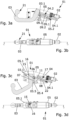
- the 1 shows an exploded drawing of a trailer hitch 01 according to the invention according to a first embodiment.
- the first embodiment of the trailer hitch 01 is characterized in that a single drive 02 is provided for transferring the coupling arm 03 between the working position and the rest position of the coupling arm 03.
- the trailer hitch 01 comprises an adjusting mechanism 04 and a housing part 05.
- the coupling arm 03 also includes a rotary bearing part 03.1, which is firmly connected to a tilting arm 06, which in turn is connected to an axle 07, which has axle projections 07.1 on both sides, wherein in the illustration of 1 only one of the axle projections 07.1 can be seen.
- the rotary bearing part 03.1 includes a bearing surface 03.2, which rotatably supports a receiving section 03.3 of the coupling head 03.
- the adjusting mechanism 04 has a threaded spindle 04.1 and a triple joint 04.2.
- the triple joint 04.2 comprises a pair of drive levers 08, which are rotatably connected via a first joint 09.1 to a head 04.3 of the threaded spindle 04.1.
- the pair of drive levers 08 is rotatably connected to a second end 10 of a locking element 11 via a second joint 09.2.
- a first end 12 of the locking element 11 includes a further joint mount 09.4, which, together with a bolt 03.4 of the pivot bearing part 03.1, forms a third joint 09.3 with the pivot bearing part 03.1 of the coupling arm 03.
- the drive 02 includes a gear 02.2 and a bearing cover 02.3 with corresponding fastening means 02.4 for fastening the drive 02 to the housing part 05.
- the drive 02 also includes a spindle nut 02.5, with which the threaded spindle 04.1 is driven.
- the housing part 05 has two side walls 05.1, which are connected to one another on a first end face 05.2 and a second end face 05.3.
- the side walls 05.1 of the housing part 05 also have link openings 05.4, which form a link 05.5.
- the link 05.5 includes a rotation section 05.8 and a translation section 05.9.
- Devices 05.6 for at least partially accommodating the drive 02 are provided on the first end face 05.2 of the housing part 05.
- anti-rotation elements 13 Arranged on the second end face 05.3 of the housing part 05 are anti-rotation elements 13 which can be brought into engagement with anti-rotation elements 14 of the coupling arm 03 of complementary design.
- the anti-rotation elements 13, 14 are designed as spherical cap combination.
- a rack 15 which, together with the pinion 16 provided on the coupling arm 03, forms a rack and pinion drive.
- a first guide means 17 is also arranged inside the housing part 05, which forms a support stop 19 for the locking element 11 at an end 18 which faces away from the drive 02.
- a second guide means 20 is also arranged, which in the perspective view of FIG 1 however, is not recognizable.
- the second guide means 22 runs essentially parallel to the first guide means 17.
- the locking element 11 further includes a stop means 11.1.
- the stop means 11.1 is designed as a pin that protrudes on both sides of the locking element 11 and limits the angle that the locking element 11 and the pair of drive levers 08 can assume in relation to one another.
- the drive levers 08 have a profile 08.1 on their edges facing the guide means 17.
- the profiling 08.1 and the stop means 11.1 are used to safely and easily reach the locking position of the locking element or to hold the coupling arm in the working position by the locking element. On the profiling 08.1 and the sling 11.1 is in the description of Figure 5i dealt with in more detail.
- the hitch of the 2 largely corresponds to the embodiment of FIG 1 . Accordingly, parts that develop a corresponding technical effect are provided with the same reference numerals as the corresponding parts of the trailer hitch according to the first embodiment 1 .
- the embodiment of 2 differs from the embodiment of 1 on the one hand by the design of the drive 02.
- the embodiment of the 2 from the embodiment of 1 in that the trailer coupling 01 has a second drive 20, which causes the coupling arm 03 to rotate about an axis of rotation A1 when the coupling arm 03 is transferred between the working position and the rest position.
- the second drive 20 sees a representation of the 2 not shown, which engages with the pinion 16 arranged on the coupling arm 03, whereby via the second drive 20, when the drive 20 is attached to the rotary bearing part 03.1 via a bracket 28, an actuation of the second drive 20 results in the Coupling arm 03 is rotated about the axis of rotation A1. Since the rotation of the coupling arm 03 is accomplished by the second drive 20, the trailer hitch 01 according to the embodiment of FIG 2 no rack 15, as in the embodiment of 1 is needed.
- the embodiments also differ in the shape of the slides 05.5 and/or the slide openings 05.4, with the function or functions of the slides 05.5 being identical.
- the links 05.5 also both have a translation section 05.9 and a rotation section 05.8.
- the different shape of the wings is due to the different drive concepts with exactly one drive 02 ( 1 ) and two drives 02, 20 ( 2 ) and due to the fact that in the embodiment of the 1 a rotation of the coupling arm 03 relative to the trailer hitch and relative to the pivot bearing part 03.1 must be effected indirectly by a translation of the pivot bearing part 03.1. Therefore falls in the embodiment 1 the translation section 05.9 of the link 05.5 is correspondingly longer than in the embodiment of FIG 2 .
- the Figures 3a and 3b show a trailer coupling 01 with a coupling arm 03, which is in the rest position 21.
- the Figure 3a shows a section through the trailer hitch 01 along the in the Figure 3b shown level AA.
- the drive 02 has moved or pulled out the threaded spindle 04.1 as far as possible from the first end face 05.2 of the housing part 05.
- the Figures 3c and 3d show the trailer coupling 01 in an intermediate state, ie with the coupling arm 03 in an intermediate position between the rest position and the working position.
- the 3c a section through the trailer hitch 01 along the in the 3d represented level AA.
- the threaded spindle 04.1 has already been moved a little way into the interior of the housing part 05 via the drive 02.
- the angular position between the threaded spindle 04.1, the drive levers 08 and the locking element 11 are determined via the first guide means 17 and the second guide means 22.
- the details relating to the link openings 05.4 of the link 05.5 are more detailed with reference to the figure 5 described.
- the pair of figures 3e and 3f also represents a representation of the trailer coupling 01 according to the first embodiment, in which the coupling arm 03 assumes an intermediate position between the rest position and the working position.
- Figure 3e is again a section through the trailer hitch 01 along the in Fig. 3f shown level AA.
- Figures 3g and 3h show the trailer hitch 01 according to the invention in a manner of representation that is basically analogous to the preceding pairs of figures, with the coupling arm 03 in the representations of Figures 3g and 3h is about to attain the position of employment.
- the second end 10 of the locking element 11 is about to reach the end 18 of the first guide means 17 .
- the coupling arm 03 of the trailer hitch 01 has assumed the working position 23.
- the threaded spindle 04.1 was moved via the drive 02 into the interior of the housing part 05 to such an extent that the locking element 11 was tilted by the drive levers 08 in relation to the pivot bearing part 03.1 and the second end 10 of the locking element 11 now frictionally engages with an end 18 of the first Guide means 17 trained support stop 19 forms.
- the tilting of the locking element 11 was brought about by the drive lever 08, in addition to the corresponding dimensioning of the first guide means 17 and the support stop 19, so that the locking element 11 from the position shown in FIGS Figures 3a to 3h shown release position or release positions in the Figure 3i shown locking position 24 could be transferred.
- the triple joint 04.2 including the locking element 11 and the drive lever 08 is angled to the maximum.
- the anti-rotation elements 13 and 14 were also brought into engagement with one another and held in engagement with one another. This prevents the coupling arm 03 from rotating relative to the rotary bearing part 03.1 and relative to the housing part 05.
- the adhesion between the second end 10 of the locking element 11 and the support stop 19 can be formed by a comparably small force of the drive lever 08 on the second end 10 of the locking element 11 .
- the arrangement of the locking element 11 in the locking position 24 means that when a force is applied to the coupling arm 03, for example a force is applied in the direction R1, the result is that the corresponding opposing forces are transferred from the pivot bearing part 03.1 to the locking element 11 and via the support stop 19 and the first guide means 17 can be diverted into the housing part 05 of the trailer hitch 01 without force being introduced into the drive 02.
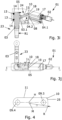
- the 4 shows a locking element 11 which, in addition to a first joint mount 09.4 and a second joint mount 09.5 at the second end 10, has an asymmetrical shape 25, in particular an asymmetrical rounding.
- the asymmetrical shape 25 is formed by an arc of a circle with the radius R, with the center point M belonging to the arc of the circle being arranged eccentrically outside the lever axis H of the locking element 11 .
- the asymmetrical rounding 25 increases the bracing force when the locking element 11 assumes the locking position 24 .
- the asymmetrical shape 25 can be used to compensate for tolerances and wear.
- the asymmetrical shape 25 also means that the locking position 24 of the locking element 11 is designed to be self-locking and can be easily reached and released again via the actuating mechanism 04.
- FIGS. 5a, 5c , 5e, 5g and 5i show sections through towbars according to the invention according to the second embodiment, as shown in the illustration in FIG 2 is shown.
- the transfer shown in the sections of the coupling arm 03 from the rest position 21 according to Figure 5a in the working position 23 according to the Figure 5i takes place largely in parallel with the corresponding processes, as they relate to the Figures 3a to 3j have been described. Accordingly, the comments on the 3 to get expelled.
- the stop means 11.1 ensures that the deflection between the locking element 11 and the drive levers 08 is limited, since when the locking position 24 of the locking element 11 is reached or shortly after, the ones opposite the profile 08.1 Edges of the drive levers 08 come to rest on the stop means 11.1, ie on the pin protruding laterally beyond the locking element 11, and thus block further rotation of the second joint 09.2.
- the stop means 11.1 and the profile 08.1 are used in the embodiment of 1 and 3 same purpose, what for example in the representation of Figure 3i is recognizable.
- the rotation of the coupling arm 03 can be decoupled from other movements during the transfer of the coupling arm 03 between the rest position and the working position and/or can be carried out independently. This allows the movements to be optimally coordinated.
- the axial projection is 07.1 in a rotating section 05.8 of the link 05.5, as shown in the illustration Figure 5b is shown. Because the approximately hook-shaped axle projection 07.1 is located in the rotating section 05.8 of the connecting link 05.5, the tilting arm 06 is rotated by rotating the axle 07 when the first drive 02 ( Figure 5a ) a force is exerted on the adjusting mechanism 04, by which the threaded spindle 04.1 is moved into the housing part 05.
- link opening 05.4 of link 05.5 is designed in such a way that rotation of axis 07 is prevented again when tilting arm 06 and thus also pivot bearing part 03.1 have assumed the position as shown, for example, in FIGS Figures 5c and 5d are shown.
- link 05.5 includes a translation section 05.9, which is designed with respect to axle projection 07.1 in such a way that when coupling arm 03 is further transferred from working position 23 to rest position 21 or vice versa, axis 07 is translated along link 05.5 and via the Tilting arm 06 accordingly also translates the pivot bearing part 03.1 and the coupling arm 03.
- the translational movements are, for example, between the representations of the Figures 5e and 5g and 5f and 5h, respectively. How to use the Fig. 5g can further see, the link is 05.5 designed such that in the working position 23 of the coupling arm 03, as for example in the Figure 5i is shown, a rotation of the axis 07 is prevented.
- the link 05.5 of the first embodiment of the trailer hitch 01 has the same shape as the link 05.5 of the second embodiment figure 5 .
- the corresponding axle projections 07.1 can also be designed slightly differently, which is the case, for example, when comparing the Figures 1 and 2 becomes evident.
Landscapes
- Engineering & Computer Science (AREA)
- Transportation (AREA)
- Mechanical Engineering (AREA)
- Arrangement And Mounting Of Devices That Control Transmission Of Motive Force (AREA)
- Agricultural Machines (AREA)
- Mechanical Operated Clutches (AREA)
Claims (12)
- Attelage de remorque de véhicules, ledit attelage comprenant un bras d'attelage mobile (03) qui peut être déplacé entre une position de travail (23) et une position de repos (21) à l'aide d'au moins un entraînement (02), un élément de blocage (11) étant prévu qui maintient le bras d'attelage (03) dans la position de travail (23) de façon à réduire au moins l'application de forces sur au moins un entraînement (02) lorsque des forces sont exercées sur le bras d'attelage (03),
caractérisé en ce que
l'élément de blocage (11) est conçu comme une partie d'un mécanisme de réglage (04) entraîné par un entraînement (02) et destiné à transférer le bras d'attelage (03) entre la position de travail (23) et la position de repos (21), l'élément de blocage (11) est relié, à une première extrémité (12), à une partie de palier rotatif (03.1) du bras d'attelage (03) par le biais d'une articulation (09.3), l'élément de blocage (11) est déplacé entre la position de blocage (24) et une position de libération par basculement par rapport à la partie de palier rotatif (03.1), l'élément de blocage (11) vient en contact avec une butée d'appui (19) dans la position de blocage (24). - Attelage de remorque selon la revendication 1,
caractérisé en ce que
l'élément de blocage (11) maintient le bras d'attelage (03) dans la position de travail (23) de façon à maintenir sans force au moins un entraînement (02) lorsque des forces sont exercées sur le bras d'attelage (03). - Attelage de remorque selon l'une des revendications 1 et 2,
caractérisé en ce que
l'élément de blocage (11) est placé dans une position de libération pour transmettre des forces entre un entraînement (02) et le bras d'attelage (03). - Attelage de remorque selon l'une des revendications 1 à 3,
caractérisé en ce que
l'élément de blocage (11) comporte au moins un logement d'articulation (09.4, 09.5). - Attelage de remorque selon l'une des revendications 1 à 4,
caractérisé en ce que
l'élément de blocage (11) vient en contact avec une butée d'appui (19) dans la position de blocage (24), avec une deuxième extrémité (10) de l'élément de blocage (11). - Attelage de remorque selon l'une des revendications 1 à 5,
caractérisé en ce que
l'élément de blocage (11) présente une forme asymétrique (25), notamment un arrondi, à une deuxième extrémité (10). - Attelage de remorque selon l'une des revendications 1 à 6,
caractérisé en ce que
l'élément de blocage (11) est conçu comme un bras d'une triple articulation (04.2). - Attelage de remorque selon la revendication 7,
caractérisé par
au moins deux moyens de guidage (17, 22) qui limitent la position relative des bras de la triple articulation (04.2) les uns par rapport aux autres lorsque le bras d'attelage (03) est transféré entre la position de repos (21) et la position de travail (23). - Attelage de remorque selon l'une des revendications 1 à 8,
caractérisé en ce que
une partie de palier rotatif (03.1) du bras d'attelage (03) est reliée rigidement à un bras basculant (06). - Attelage de remorque selon la revendication 9,
caractérisé en ce que
le bras basculant (06) est relié rigidement, à une extrémité opposée à la partie de palier rotatif (03.1), à un axe (07) qui est guidé dans une coulisse (05.5), notamment par le biais d'au moins une saillie d'axe (07.1). - Attelage de remorque selon l'une des revendications 1 à 10,
caractérisé par
exactement un entraînement (02) destiné à transférer le bras d'attelage (03) entre une position de travail (23) et une position de repos (21). - Attelage de remorque selon l'une des revendications 1 à 10,
caractérisé en ce que
lorsque le bras d'accouplement (03) est transféré entre la position de travail (23) et la position de repos (21), un premier entraînement (02) cause la translation et le basculement de la partie de palier rotatif (03.1) et un deuxième entraînement (20) cause la rotation du bras d'accouplement (03).
Applications Claiming Priority (1)
| Application Number | Priority Date | Filing Date | Title |
|---|---|---|---|
| DE102017118152.0A DE102017118152B4 (de) | 2017-08-09 | 2017-08-09 | Motorisch verschwenkbare Anhängekupplung |
Publications (3)
| Publication Number | Publication Date |
|---|---|
| EP3441243A1 EP3441243A1 (fr) | 2019-02-13 |
| EP3441243B1 EP3441243B1 (fr) | 2020-07-01 |
| EP3441243B2 true EP3441243B2 (fr) | 2023-08-09 |
Family
ID=63168304
Family Applications (1)
| Application Number | Title | Priority Date | Filing Date |
|---|---|---|---|
| EP18187661.6A Active EP3441243B2 (fr) | 2017-08-09 | 2018-08-07 | Attelage de remorque pouvant pivoter de manière motorisée |
Country Status (2)
| Country | Link |
|---|---|
| EP (1) | EP3441243B2 (fr) |
| DE (1) | DE102017118152B4 (fr) |
Citations (18)
| Publication number | Priority date | Publication date | Assignee | Title |
|---|---|---|---|---|
| WO1998057813A1 (fr) † | 1997-06-19 | 1998-12-23 | Volvo Personvagnar Ab | Dispositif d'attelage pour vehicules |
| DE10017013A1 (de) † | 2000-04-05 | 2001-10-18 | Oris Fahrzeugteile Riehle H | Anhängekupplung |
| DE10104185A1 (de) † | 2001-01-23 | 2002-07-25 | Fac Frank Abels Consult & Tech | Anhängerkupplung |
| EP1380445A1 (fr) † | 2002-07-11 | 2004-01-14 | Dr.Ing. h.c.F. Porsche Aktiengesellschaft | Dispositif de traction de remorque |
| EP1407901A1 (fr) † | 2002-10-09 | 2004-04-14 | Al-Ko Kober Ag | Attelage pour véhicules de traction |
| EP1488943A1 (fr) † | 2003-06-20 | 2004-12-22 | Westfalia Automotive GmbH & Co. KG | Dispositif d'attelage motorisé pour véhicules |
| EP1491369A1 (fr) † | 2003-06-26 | 2004-12-29 | ORIS FAHRZEUGTEILE HANS RIEHLE GmbH | Attelage pour vehicules |
| EP1504928A1 (fr) † | 2003-08-08 | 2005-02-09 | Westfalia Automotive GmbH & Co. KG | Attache remorque |
| EP1541385A1 (fr) † | 2003-12-13 | 2005-06-15 | Westfalia Automotive GmbH & Co. KG | Attache remorque |
| EP1561610A1 (fr) † | 2004-02-09 | 2005-08-10 | Westfalia-Automotive GmbH & Co. KG | Mecanisme d'attelage |
| EP1584499A1 (fr) † | 2004-04-08 | 2005-10-12 | Westfalia-Automotive GmbH & Co. KG | Attelage de remorque |
| EP1584500A1 (fr) † | 2004-04-08 | 2005-10-12 | Westfalia-Automotive GmbH & Co. KG | Attelage de remorque |
| EP1586471A1 (fr) † | 2004-04-17 | 2005-10-19 | Westfalia-Automotive GmbH & Co. KG | Attelage de remorque |
| DE102004051976A1 (de) † | 2004-10-25 | 2006-04-27 | Westfalia-Automotive Gmbh & Co. Kg | Anhängerkupplung für Kraftfahrzeuge |
| EP1790504A1 (fr) † | 2005-11-25 | 2007-05-30 | Jaeger Cartronix GmbH | Unité d'entraînement pour un attelage de remorque |
| DE102006033031B4 (de) † | 2006-07-14 | 2008-07-24 | Paragon Ag | Anhängerkupplung für Kraftfahrzeuge |
| EP2233326A1 (fr) † | 2009-03-25 | 2010-09-29 | SCAMBIA Industrial Developments Aktiengesellschaft | Attelage |
| DE202015104504U1 (de) † | 2015-06-12 | 2016-09-13 | Ercan Mutlu | Anhängerkupplung |
Family Cites Families (3)
| Publication number | Priority date | Publication date | Assignee | Title |
|---|---|---|---|---|
| DE19858978C5 (de) * | 1998-12-19 | 2012-06-06 | Westfalia-Automotive Gmbh | Schwenkbare Anhängerkupplung für Kraftfahrzeuge |
| DE10004523A1 (de) * | 2000-02-02 | 2001-08-09 | Fac Frank Abels Consult & Tech | Anhängerkupplung |
| DE102004045869A1 (de) * | 2004-09-20 | 2006-03-23 | Jaeger Cartronix Gmbh | Anhängerkupplung |
-
2017
- 2017-08-09 DE DE102017118152.0A patent/DE102017118152B4/de active Active
-
2018
- 2018-08-07 EP EP18187661.6A patent/EP3441243B2/fr active Active
Patent Citations (18)
| Publication number | Priority date | Publication date | Assignee | Title |
|---|---|---|---|---|
| WO1998057813A1 (fr) † | 1997-06-19 | 1998-12-23 | Volvo Personvagnar Ab | Dispositif d'attelage pour vehicules |
| DE10017013A1 (de) † | 2000-04-05 | 2001-10-18 | Oris Fahrzeugteile Riehle H | Anhängekupplung |
| DE10104185A1 (de) † | 2001-01-23 | 2002-07-25 | Fac Frank Abels Consult & Tech | Anhängerkupplung |
| EP1380445A1 (fr) † | 2002-07-11 | 2004-01-14 | Dr.Ing. h.c.F. Porsche Aktiengesellschaft | Dispositif de traction de remorque |
| EP1407901A1 (fr) † | 2002-10-09 | 2004-04-14 | Al-Ko Kober Ag | Attelage pour véhicules de traction |
| EP1488943A1 (fr) † | 2003-06-20 | 2004-12-22 | Westfalia Automotive GmbH & Co. KG | Dispositif d'attelage motorisé pour véhicules |
| EP1491369A1 (fr) † | 2003-06-26 | 2004-12-29 | ORIS FAHRZEUGTEILE HANS RIEHLE GmbH | Attelage pour vehicules |
| EP1504928A1 (fr) † | 2003-08-08 | 2005-02-09 | Westfalia Automotive GmbH & Co. KG | Attache remorque |
| EP1541385A1 (fr) † | 2003-12-13 | 2005-06-15 | Westfalia Automotive GmbH & Co. KG | Attache remorque |
| EP1561610A1 (fr) † | 2004-02-09 | 2005-08-10 | Westfalia-Automotive GmbH & Co. KG | Mecanisme d'attelage |
| EP1584499A1 (fr) † | 2004-04-08 | 2005-10-12 | Westfalia-Automotive GmbH & Co. KG | Attelage de remorque |
| EP1584500A1 (fr) † | 2004-04-08 | 2005-10-12 | Westfalia-Automotive GmbH & Co. KG | Attelage de remorque |
| EP1586471A1 (fr) † | 2004-04-17 | 2005-10-19 | Westfalia-Automotive GmbH & Co. KG | Attelage de remorque |
| DE102004051976A1 (de) † | 2004-10-25 | 2006-04-27 | Westfalia-Automotive Gmbh & Co. Kg | Anhängerkupplung für Kraftfahrzeuge |
| EP1790504A1 (fr) † | 2005-11-25 | 2007-05-30 | Jaeger Cartronix GmbH | Unité d'entraînement pour un attelage de remorque |
| DE102006033031B4 (de) † | 2006-07-14 | 2008-07-24 | Paragon Ag | Anhängerkupplung für Kraftfahrzeuge |
| EP2233326A1 (fr) † | 2009-03-25 | 2010-09-29 | SCAMBIA Industrial Developments Aktiengesellschaft | Attelage |
| DE202015104504U1 (de) † | 2015-06-12 | 2016-09-13 | Ercan Mutlu | Anhängerkupplung |
Also Published As
| Publication number | Publication date |
|---|---|
| EP3441243B1 (fr) | 2020-07-01 |
| DE102017118152A1 (de) | 2019-02-14 |
| EP3441243A1 (fr) | 2019-02-13 |
| DE102017118152B4 (de) | 2020-09-24 |
Similar Documents
| Publication | Publication Date | Title |
|---|---|---|
| EP1557298B2 (fr) | Attelage de remorque | |
| DE19654867C2 (de) | Schwenkbare Anhängerkupplung für Kraftfahrzeuge | |
| EP2567835B1 (fr) | Attelage | |
| EP1288026B2 (fr) | Attelage de remorque | |
| EP1359051B1 (fr) | Ferrure d'articulation de dossier pour un siège d'automobile | |
| EP2792514B1 (fr) | Attelage | |
| EP1880879B1 (fr) | Dispositif d'attelage pivotant pour tracteurs | |
| EP1894752B2 (fr) | Attelage de remorque avec crochet extensible et rétractable | |
| EP1182062A2 (fr) | Attelage de remorque | |
| DE10243045B4 (de) | Anhängerkupplung | |
| DE10243044B4 (de) | Anhängerkupplung | |
| EP1407901B1 (fr) | Attelage pour véhicules de traction | |
| DE19944082A1 (de) | Schwenkbare Anhängerkupplung mit selbsttätiger Verriegelung | |
| EP1491369B1 (fr) | Attelage pour vehicules | |
| EP2792513B1 (fr) | Attelage | |
| DE19958300B4 (de) | Verstellvorrichtung für einen Kraftfahrzeugsitz mit einem Klemmgesperre, das ein erstes Gesperreteil und ein zweites Gesperreteil hat | |
| DE102014011348A1 (de) | Anhängekupplung mit einem Baukastensystem | |
| EP1544003B1 (fr) | Dispositif d'attelage pour véhicules automobiles | |
| EP3441243B2 (fr) | Attelage de remorque pouvant pivoter de manière motorisée | |
| EP2181868B1 (fr) | Attelage | |
| EP2799261B1 (fr) | Attelage | |
| DE102006051096B4 (de) | Anhängevorrichtung | |
| EP2796303B1 (fr) | Attelage | |
| EP2796305B1 (fr) | Attelage | |
| DE102022122865A1 (de) | Anhängekupplung |
Legal Events
| Date | Code | Title | Description |
|---|---|---|---|
| PUAI | Public reference made under article 153(3) epc to a published international application that has entered the european phase |
Free format text: ORIGINAL CODE: 0009012 |
|
| STAA | Information on the status of an ep patent application or granted ep patent |
Free format text: STATUS: THE APPLICATION HAS BEEN PUBLISHED |
|
| AK | Designated contracting states |
Kind code of ref document: A1 Designated state(s): AL AT BE BG CH CY CZ DE DK EE ES FI FR GB GR HR HU IE IS IT LI LT LU LV MC MK MT NL NO PL PT RO RS SE SI SK SM TR |
|
| AX | Request for extension of the european patent |
Extension state: BA ME |
|
| STAA | Information on the status of an ep patent application or granted ep patent |
Free format text: STATUS: REQUEST FOR EXAMINATION WAS MADE |
|
| 17P | Request for examination filed |
Effective date: 20190813 |
|
| RBV | Designated contracting states (corrected) |
Designated state(s): AL AT BE BG CH CY CZ DE DK EE ES FI FR GB GR HR HU IE IS IT LI LT LU LV MC MK MT NL NO PL PT RO RS SE SI SK SM TR |
|
| STAA | Information on the status of an ep patent application or granted ep patent |
Free format text: STATUS: EXAMINATION IS IN PROGRESS |
|
| 17Q | First examination report despatched |
Effective date: 20191008 |
|
| GRAP | Despatch of communication of intention to grant a patent |
Free format text: ORIGINAL CODE: EPIDOSNIGR1 |
|
| STAA | Information on the status of an ep patent application or granted ep patent |
Free format text: STATUS: GRANT OF PATENT IS INTENDED |
|
| INTG | Intention to grant announced |
Effective date: 20200221 |
|
| GRAS | Grant fee paid |
Free format text: ORIGINAL CODE: EPIDOSNIGR3 |
|
| GRAA | (expected) grant |
Free format text: ORIGINAL CODE: 0009210 |
|
| STAA | Information on the status of an ep patent application or granted ep patent |
Free format text: STATUS: THE PATENT HAS BEEN GRANTED |
|
| AK | Designated contracting states |
Kind code of ref document: B1 Designated state(s): AL AT BE BG CH CY CZ DE DK EE ES FI FR GB GR HR HU IE IS IT LI LT LU LV MC MK MT NL NO PL PT RO RS SE SI SK SM TR |
|
| REG | Reference to a national code |
Ref country code: AT Ref legal event code: REF Ref document number: 1285838 Country of ref document: AT Kind code of ref document: T Effective date: 20200715 Ref country code: CH Ref legal event code: EP |
|
| REG | Reference to a national code |
Ref country code: IE Ref legal event code: FG4D Free format text: LANGUAGE OF EP DOCUMENT: GERMAN |
|
| REG | Reference to a national code |
Ref country code: DE Ref legal event code: R096 Ref document number: 502018001785 Country of ref document: DE |
|
| REG | Reference to a national code |
Ref country code: CH Ref legal event code: NV Representative=s name: VALIPAT S.A. C/O BOVARD SA NEUCHATEL, CH |
|
| REG | Reference to a national code |
Ref country code: NL Ref legal event code: FP |
|
| REG | Reference to a national code |
Ref country code: LT Ref legal event code: MG4D |
|
| PG25 | Lapsed in a contracting state [announced via postgrant information from national office to epo] |
Ref country code: BG Free format text: LAPSE BECAUSE OF FAILURE TO SUBMIT A TRANSLATION OF THE DESCRIPTION OR TO PAY THE FEE WITHIN THE PRESCRIBED TIME-LIMIT Effective date: 20201001 |
|
| PG25 | Lapsed in a contracting state [announced via postgrant information from national office to epo] |
Ref country code: ES Free format text: LAPSE BECAUSE OF FAILURE TO SUBMIT A TRANSLATION OF THE DESCRIPTION OR TO PAY THE FEE WITHIN THE PRESCRIBED TIME-LIMIT Effective date: 20200701 Ref country code: HR Free format text: LAPSE BECAUSE OF FAILURE TO SUBMIT A TRANSLATION OF THE DESCRIPTION OR TO PAY THE FEE WITHIN THE PRESCRIBED TIME-LIMIT Effective date: 20200701 Ref country code: LT Free format text: LAPSE BECAUSE OF FAILURE TO SUBMIT A TRANSLATION OF THE DESCRIPTION OR TO PAY THE FEE WITHIN THE PRESCRIBED TIME-LIMIT Effective date: 20200701 Ref country code: CZ Free format text: LAPSE BECAUSE OF FAILURE TO SUBMIT A TRANSLATION OF THE DESCRIPTION OR TO PAY THE FEE WITHIN THE PRESCRIBED TIME-LIMIT Effective date: 20200701 Ref country code: FI Free format text: LAPSE BECAUSE OF FAILURE TO SUBMIT A TRANSLATION OF THE DESCRIPTION OR TO PAY THE FEE WITHIN THE PRESCRIBED TIME-LIMIT Effective date: 20200701 Ref country code: GR Free format text: LAPSE BECAUSE OF FAILURE TO SUBMIT A TRANSLATION OF THE DESCRIPTION OR TO PAY THE FEE WITHIN THE PRESCRIBED TIME-LIMIT Effective date: 20201002 Ref country code: SE Free format text: LAPSE BECAUSE OF FAILURE TO SUBMIT A TRANSLATION OF THE DESCRIPTION OR TO PAY THE FEE WITHIN THE PRESCRIBED TIME-LIMIT Effective date: 20200701 Ref country code: PT Free format text: LAPSE BECAUSE OF FAILURE TO SUBMIT A TRANSLATION OF THE DESCRIPTION OR TO PAY THE FEE WITHIN THE PRESCRIBED TIME-LIMIT Effective date: 20201102 Ref country code: NO Free format text: LAPSE BECAUSE OF FAILURE TO SUBMIT A TRANSLATION OF THE DESCRIPTION OR TO PAY THE FEE WITHIN THE PRESCRIBED TIME-LIMIT Effective date: 20201001 |
|
| PG25 | Lapsed in a contracting state [announced via postgrant information from national office to epo] |
Ref country code: IS Free format text: LAPSE BECAUSE OF FAILURE TO SUBMIT A TRANSLATION OF THE DESCRIPTION OR TO PAY THE FEE WITHIN THE PRESCRIBED TIME-LIMIT Effective date: 20201101 Ref country code: RS Free format text: LAPSE BECAUSE OF FAILURE TO SUBMIT A TRANSLATION OF THE DESCRIPTION OR TO PAY THE FEE WITHIN THE PRESCRIBED TIME-LIMIT Effective date: 20200701 Ref country code: PL Free format text: LAPSE BECAUSE OF FAILURE TO SUBMIT A TRANSLATION OF THE DESCRIPTION OR TO PAY THE FEE WITHIN THE PRESCRIBED TIME-LIMIT Effective date: 20200701 Ref country code: LV Free format text: LAPSE BECAUSE OF FAILURE TO SUBMIT A TRANSLATION OF THE DESCRIPTION OR TO PAY THE FEE WITHIN THE PRESCRIBED TIME-LIMIT Effective date: 20200701 |
|
| REG | Reference to a national code |
Ref country code: DE Ref legal event code: R026 Ref document number: 502018001785 Country of ref document: DE |
|
| PLBI | Opposition filed |
Free format text: ORIGINAL CODE: 0009260 |
|
| PG25 | Lapsed in a contracting state [announced via postgrant information from national office to epo] |
Ref country code: MC Free format text: LAPSE BECAUSE OF FAILURE TO SUBMIT A TRANSLATION OF THE DESCRIPTION OR TO PAY THE FEE WITHIN THE PRESCRIBED TIME-LIMIT Effective date: 20200701 |
|
| PLBI | Opposition filed |
Free format text: ORIGINAL CODE: 0009260 |
|
| PLAX | Notice of opposition and request to file observation + time limit sent |
Free format text: ORIGINAL CODE: EPIDOSNOBS2 |
|
| 26 | Opposition filed |
Opponent name: BRINK TOWING SYSTEMS B.V. Effective date: 20210323 |
|
| PG25 | Lapsed in a contracting state [announced via postgrant information from national office to epo] |
Ref country code: IT Free format text: LAPSE BECAUSE OF FAILURE TO SUBMIT A TRANSLATION OF THE DESCRIPTION OR TO PAY THE FEE WITHIN THE PRESCRIBED TIME-LIMIT Effective date: 20200701 Ref country code: SM Free format text: LAPSE BECAUSE OF FAILURE TO SUBMIT A TRANSLATION OF THE DESCRIPTION OR TO PAY THE FEE WITHIN THE PRESCRIBED TIME-LIMIT Effective date: 20200701 Ref country code: LU Free format text: LAPSE BECAUSE OF NON-PAYMENT OF DUE FEES Effective date: 20200807 Ref country code: DK Free format text: LAPSE BECAUSE OF FAILURE TO SUBMIT A TRANSLATION OF THE DESCRIPTION OR TO PAY THE FEE WITHIN THE PRESCRIBED TIME-LIMIT Effective date: 20200701 Ref country code: RO Free format text: LAPSE BECAUSE OF FAILURE TO SUBMIT A TRANSLATION OF THE DESCRIPTION OR TO PAY THE FEE WITHIN THE PRESCRIBED TIME-LIMIT Effective date: 20200701 Ref country code: EE Free format text: LAPSE BECAUSE OF FAILURE TO SUBMIT A TRANSLATION OF THE DESCRIPTION OR TO PAY THE FEE WITHIN THE PRESCRIBED TIME-LIMIT Effective date: 20200701 |
|
| PLAB | Opposition data, opponent's data or that of the opponent's representative modified |
Free format text: ORIGINAL CODE: 0009299OPPO |
|
| 26 | Opposition filed |
Opponent name: ACPS AUTOMOTIVE GMBH Effective date: 20210330 |
|
| REG | Reference to a national code |
Ref country code: BE Ref legal event code: MM Effective date: 20200831 |
|
| PG25 | Lapsed in a contracting state [announced via postgrant information from national office to epo] |
Ref country code: AL Free format text: LAPSE BECAUSE OF FAILURE TO SUBMIT A TRANSLATION OF THE DESCRIPTION OR TO PAY THE FEE WITHIN THE PRESCRIBED TIME-LIMIT Effective date: 20200701 |
|
| R26 | Opposition filed (corrected) |
Opponent name: BRINK TOWING SYSTEMS B.V. Effective date: 20210323 |
|
| PG25 | Lapsed in a contracting state [announced via postgrant information from national office to epo] |
Ref country code: SK Free format text: LAPSE BECAUSE OF FAILURE TO SUBMIT A TRANSLATION OF THE DESCRIPTION OR TO PAY THE FEE WITHIN THE PRESCRIBED TIME-LIMIT Effective date: 20200701 |
|
| PLBB | Reply of patent proprietor to notice(s) of opposition received |
Free format text: ORIGINAL CODE: EPIDOSNOBS3 |
|
| PG25 | Lapsed in a contracting state [announced via postgrant information from national office to epo] |
Ref country code: IE Free format text: LAPSE BECAUSE OF NON-PAYMENT OF DUE FEES Effective date: 20200807 Ref country code: SI Free format text: LAPSE BECAUSE OF FAILURE TO SUBMIT A TRANSLATION OF THE DESCRIPTION OR TO PAY THE FEE WITHIN THE PRESCRIBED TIME-LIMIT Effective date: 20200701 Ref country code: BE Free format text: LAPSE BECAUSE OF NON-PAYMENT OF DUE FEES Effective date: 20200831 |
|
| PG25 | Lapsed in a contracting state [announced via postgrant information from national office to epo] |
Ref country code: TR Free format text: LAPSE BECAUSE OF FAILURE TO SUBMIT A TRANSLATION OF THE DESCRIPTION OR TO PAY THE FEE WITHIN THE PRESCRIBED TIME-LIMIT Effective date: 20200701 Ref country code: MT Free format text: LAPSE BECAUSE OF FAILURE TO SUBMIT A TRANSLATION OF THE DESCRIPTION OR TO PAY THE FEE WITHIN THE PRESCRIBED TIME-LIMIT Effective date: 20200701 Ref country code: CY Free format text: LAPSE BECAUSE OF FAILURE TO SUBMIT A TRANSLATION OF THE DESCRIPTION OR TO PAY THE FEE WITHIN THE PRESCRIBED TIME-LIMIT Effective date: 20200701 |
|
| PG25 | Lapsed in a contracting state [announced via postgrant information from national office to epo] |
Ref country code: MK Free format text: LAPSE BECAUSE OF FAILURE TO SUBMIT A TRANSLATION OF THE DESCRIPTION OR TO PAY THE FEE WITHIN THE PRESCRIBED TIME-LIMIT Effective date: 20200701 |
|
| P01 | Opt-out of the competence of the unified patent court (upc) registered |
Effective date: 20230519 |
|
| PUAH | Patent maintained in amended form |
Free format text: ORIGINAL CODE: 0009272 |
|
| STAA | Information on the status of an ep patent application or granted ep patent |
Free format text: STATUS: PATENT MAINTAINED AS AMENDED |
|
| 27A | Patent maintained in amended form |
Effective date: 20230809 |
|
| AK | Designated contracting states |
Kind code of ref document: B2 Designated state(s): AL AT BE BG CH CY CZ DE DK EE ES FI FR GB GR HR HU IE IS IT LI LT LU LV MC MK MT NL NO PL PT RO RS SE SI SK SM TR |
|
| REG | Reference to a national code |
Ref country code: DE Ref legal event code: R102 Ref document number: 502018001785 Country of ref document: DE |
|
| REG | Reference to a national code |
Ref country code: NL Ref legal event code: FP |
|
| PGFP | Annual fee paid to national office [announced via postgrant information from national office to epo] |
Ref country code: NL Payment date: 20250821 Year of fee payment: 8 |
|
| PGFP | Annual fee paid to national office [announced via postgrant information from national office to epo] |
Ref country code: DE Payment date: 20250831 Year of fee payment: 8 |
|
| PGFP | Annual fee paid to national office [announced via postgrant information from national office to epo] |
Ref country code: GB Payment date: 20250822 Year of fee payment: 8 |
|
| PGFP | Annual fee paid to national office [announced via postgrant information from national office to epo] |
Ref country code: FR Payment date: 20250821 Year of fee payment: 8 Ref country code: AT Payment date: 20250819 Year of fee payment: 8 |
|
| PGFP | Annual fee paid to national office [announced via postgrant information from national office to epo] |
Ref country code: CH Payment date: 20250901 Year of fee payment: 8 |