EP1879667B1 - Dispositif de securite pour boucle de ceinture de siege - Google Patents
Dispositif de securite pour boucle de ceinture de siege Download PDFInfo
- Publication number
- EP1879667B1 EP1879667B1 EP06721505A EP06721505A EP1879667B1 EP 1879667 B1 EP1879667 B1 EP 1879667B1 EP 06721505 A EP06721505 A EP 06721505A EP 06721505 A EP06721505 A EP 06721505A EP 1879667 B1 EP1879667 B1 EP 1879667B1
- Authority
- EP
- European Patent Office
- Prior art keywords
- seat belt
- safety device
- flap member
- belt buckle
- sleeve
- Prior art date
- Legal status (The legal status is an assumption and is not a legal conclusion. Google has not performed a legal analysis and makes no representation as to the accuracy of the status listed.)
- Not-in-force
Links
- 239000000463 material Substances 0.000 claims description 19
- 230000003014 reinforcing effect Effects 0.000 claims description 10
- 230000000881 depressing effect Effects 0.000 claims description 2
- 230000000994 depressogenic effect Effects 0.000 abstract description 5
- 239000004744 fabric Substances 0.000 description 8
- 239000004033 plastic Substances 0.000 description 4
- 229920003023 plastic Polymers 0.000 description 4
- 239000004743 Polypropylene Substances 0.000 description 2
- 239000000956 alloy Substances 0.000 description 2
- 230000004888 barrier function Effects 0.000 description 2
- 239000002131 composite material Substances 0.000 description 2
- 239000010985 leather Substances 0.000 description 2
- 230000004048 modification Effects 0.000 description 2
- 238000012986 modification Methods 0.000 description 2
- 229920001084 poly(chloroprene) Polymers 0.000 description 2
- -1 polypropylene Polymers 0.000 description 2
- 229920001155 polypropylene Polymers 0.000 description 2
- 229920003051 synthetic elastomer Polymers 0.000 description 2
- 239000005061 synthetic rubber Substances 0.000 description 2
- 125000000391 vinyl group Chemical group [H]C([*])=C([H])[H] 0.000 description 2
- 229920002554 vinyl polymer Polymers 0.000 description 2
- 230000001010 compromised effect Effects 0.000 description 1
- 238000009434 installation Methods 0.000 description 1
Images


Classifications
-
- A—HUMAN NECESSITIES
- A44—HABERDASHERY; JEWELLERY
- A44B—BUTTONS, PINS, BUCKLES, SLIDE FASTENERS, OR THE LIKE
- A44B11/00—Buckles; Similar fasteners for interconnecting straps or the like, e.g. for safety belts
- A44B11/25—Buckles; Similar fasteners for interconnecting straps or the like, e.g. for safety belts with two or more separable parts
- A44B11/2503—Safety buckles
- A44B11/2569—Safety measures
- A44B11/2573—Locking means preventing an unauthorised opening, e.g. by children
- A44B11/2576—Buckle covers
-
- B—PERFORMING OPERATIONS; TRANSPORTING
- B64—AIRCRAFT; AVIATION; COSMONAUTICS
- B64D—EQUIPMENT FOR FITTING IN OR TO AIRCRAFT; FLIGHT SUITS; PARACHUTES; ARRANGEMENT OR MOUNTING OF POWER PLANTS OR PROPULSION TRANSMISSIONS IN AIRCRAFT
- B64D11/00—Passenger or crew accommodation; Flight-deck installations not otherwise provided for
- B64D11/06—Arrangements of seats, or adaptations or details specially adapted for aircraft seats
- B64D11/062—Belts or other passenger restraint means for passenger seats
Definitions
- the present invention relates to a safety device for a seat belt buckle, in particular to a safety device arranged to prevent a release button of the seat belt buckle from being depressed.
- Installation of the child safety seat and secure mounting thereof on the rear seat of the vehicle involves engagement of the child safety seat with a seat belt already installed in the vehicle.
- a release button of the seat belt buckle associated with the seat belt securing the child safety seat is depressed, the secure mounting of the child safety seat is compromised.
- a young child is capable of depressing the release button.
- unintentional contact with the release button may also depress the button and compromise the safety of the child safety seat.
- the present invention seeks to overcome at least some of the aforementioned disadvantages.
- United Kingdom Patent Application No GB 2371830 A which is considered to represent the closest prior art, describes a cover for a car seat buckle according to the preamble of claim 1 in that it comprises a sleeve of flexible material which may be slid over a first part of a buckle. When in place the sleeve denies access to a release mechanism of the buckle, thus preventing accidental release of the buckle.
- the sleeve is provided with two strap parts which fold around the second buckle part and are fastened to one another by hook and loop fastening tape.
- German Gebrauchmuster No DE 200 02 899 U1 also describes a cover for a seat belt buckle comprising a box-like sleeve which may be fitted around the buckle.
- a safety device for a seat belt buckle arranged, in use, to prevent a release button of the seat belt buckle from being depressed and thereby disengaging therefrom an insert coupled to a seat belt strap
- the safety device comprising a casing for the seat belt buckle, wherein the casing is formed from a folded sheet having an elogate section with opposing side portions configured to fold around the seat belt buckle, a flap member depending from a side of the elongate section, wherein disposed in the flap member is an aperture comprising a slit or slot to receive the insert.
- the casing of the safety device is further configured to be intentionally deformable to afford ready access to the release button.
- the casing comprises a sleeve having an open lower end and an open upper end, and a flap member depending from the open upper end of the sleeve, the flap member being configured, in use, to be folded over the open upper end of the sleeve.
- the sleeve is substantially cylindrical and is configured, in use, to be fitted over the seat belt buckle.
- the sleeve is formed from an elongate section configured, in use, to be wrapped around the seat belt buckle. Opposing side portions of the elongate section are typically provided with respective fasteners. The elongate section is wrapped around the seat belt buckle in a manner whereby opposing side portions of the elongate section are spaced sufficiently closely to one another to be conjoined with respective fasteners.
- the type of fastener is selected to enable the opposing side portions of the elongate section to be readily detached from one another, such as for example in the case of an emergency where access to the release button of the seat belt buckle is required immediately in order to disengage the seat belt. Suitable examples of such fasteners include, but are not limited to, a zipper, hook and loop fastening material, buttons and corresponding button holes, snap fasteners, or hooks and eyes.
- the slit or the slot is transversely disposed in the flap member to receive the insert.
- the flap member, or each tab member is provided with a fastener to secure the flap member, or each tab member, over the open upper end of the sleeve.
- the fastener is of a type that can be quickly unfastened such that the flap member, or each tab member, can be detached and folded away from the open upper end of the sleeve thereby providing ready access to the release button of the seat belt buckle when required.
- Suitable examples of such fasteners include, but are not limited to, hook and loop fastening material, snap fasteners, hooks and eyes.
- the flap member is provided with a reinforcing member disposed contiguously on an upper and/or a lower surface of the flap member, and disposed, in use, proximal to the release button.
- the purpose of the reinforcing member is to afford additional stiffness to the flap member without overly compromising its foldability, while at the same time providing an additional barrier to access of the release button.
- the flap member is provided with opposing side wing portions which are arranged to be folded towards one another and around the seat belt buckle when the flap member is folded over the open upper end of the sleeve.
- the opposing side wing portions can be provided with a fastener such as, for example, a hook and loop material to engage a corresponding fastener disposed on an outer surface of the sleeve of the casing.
- the casing comprises a pliable sheet configured to be folded around the seat belt buckle, wherein a gap between respective edges thereof forms the aperture to receive the insert.
- the casing comprises a pliable sheet configured to be folded around the seat belt buckle, wherein the pliable sheet has a slit or slot therein configured to receive the insert.
- the pliable sheet is provided with a pair of opposing side wings which are arranged to be folded towards one another thereby substantially forming a sleeve around the seat belt buckle, and a flap member which is arranged to be folded over an open upper end of the sleeve so formed, thereby substantially encasing the seat belt buckle.
- the pliable sheet is formed from a pliable material which can be easily bent into a desired shape and retain said desired shape.
- pliable materials include, but are not limited to, a moldable plastics material, a moldable synthetic rubber, a moldable composite material, a malleable metallic or malleable alloy material, such as, for example, a wire mesh material.
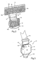
- a safety device 10 for a seat belt buckle 120 arranged, in use, to prevent a release button 122 of the seat belt buckle 120 from being depressed and thereby disengaging therefrom an insert 112 coupled to a seat belt strap 110.
- the safety device 10 comprises a casing 12 disposed around the seat belt buckle 120, wherein the casing 12 is provided with an aperture 30 to receive the insert 112.
- the casing 20 includes a sleeve 22 having an open lower end 21 and an open upper end 23 provided with a flap member 24.
- Figure 1 illustrates a net 70 corresponding to the safety device 10 shown in Figure 3 .
- the net 70 is a flat sheet of a heavy duty fabric which can be easily folded into the safety device 10. Suitable examples of such heavy duty fabrics include, but are not limited to, neoprene, vinyl fabrics, upholstery fabrics, leather, and heavy duty denim.
- the net 70 has a first side 72 and a second side 74.
- the net 70 includes an elongate section 76 and a flap member 24 depending from an upper side 71 of the elongate section 76.
- the flap member 24 of the net 70 is provided with opposing side wing portions 73a, 73b depending from a free end 75 thereof.
- the elongate section 76 and the opposing side wing portions 73a, 73b are each provided with a fastener 80a, 80b, respectively, such as, for example, a portion of a hook and loop material.
- the fastener 80b extends between the opposing side wing portions 73a, 73b and is stitched or thermal welded to the second side 74 of the net 70, whereas the fastener 80b extends substantially along the length of the elongate section 76 and is stitched or thermal welded to the first side 72 of the net 70.
- the fasteners 80a, 80b are selected to engage one another as will be described below.
- the flap member 24 is provided with a slit or slot 33.
- the slit or slot 33 is transversely disposed in the flap member 24.
- the flap member 24 is further provided with a reinforcing member 77 disposed contiguously on the first side 72 of the net 70.
- the reinforcing member 77 is stitched or thermal welded to the first side 72 of the net 70.
- the reinforcing member 77 can be formed from a sheet of plastics material, such as polypropylene.
- the elongate section 76 is configured, in use, to be folded around the seat belt buckle 120 in a manner whereby the second side 74 of the elongate section 76 is adjacent to the seat belt buckle and a sleeve 22 having an open lower end 21 and an open upper end 23 is formed, as shown in Figure 2 . In this way, the fastener 80a is exposed on an outward facing surface of the sleeve 22.
- the flap member is 24 configured, in use, to be folded over the open upper end 23 of the sleeve 22, and the opposing side wing portions 73a, 73b are also folded around the sleeve 22 thereby forming the casing 12 for the seat belt buckle 120.
- the fastener 80b on the first side 72 of the opposing side wing portions 73a, 73b is configured to engage the fastener 80a exposed on the outward facing surface of the sleeve 22.
- the sleeve 22 so formed can be fitted over the seat belt buckle 120 until the seat belt buckle 120 and the release button 122 is disposed within the sleeve 22.
- the insert 112 of the seat belt strap 110 is then inserted into slit 33 in the flap member 24 and thence into the seat belt buckle 120.
- the casing 20 comprises a sleeve 22 having an open lower end 21 and an open upper end 23 provided with a flap member 24.
- the sleeve 22 and the flap member 24 will be formed from a heavy duty fabric which can be easily folded into a desired shape and substantially retain said desired shape.
- Suitable examples of such heavy duty fabrics include, but are not limited to, neoprene, vinyl fabrics, upholstery fabrics, leather, and heavy duty denim.
- the sleeve 22 and its open lower end 21 are sufficiently wide to be fitted over the seat belt buckle 120 and the release button 122, as shown in Figure 4 .
- the sleeve 22 is cylindrical in shape.
- the sleeve 22 can be formed as an integral cylindrical sleeve with longitudinal seam 28 or as an elongate section whose opposing side edges or side portions are provided with corresponding fasteners extending substantially along the length of the side edges or side portions.
- Suitable examples of such fasteners include, but are not limited to, zippers, hook and loop fastening material, buttons, or press studs, to enable the opposing side edges or side portions to be conjoined, thereby forming the cylindrical sleeve with longitudinal seam 28.
- the type of fastener is selected to enable the longitudinal seam 28 to be readily torn open if immediate access to the release button 122 is required, such as in an emergency.
- the longitudinal seam 28 can be stitched or thermal welded.
- the flap member 24 depends from and substantially along a rear side 25 of the open upper end 23 of the sleeve 22.
- the flap member 24 is typically rectangular in shape and it is configured to be folded over a front side 27 of the open upper end 23 of the sleeve 20, thereby substantially encasing the seat belt buckle 120.
- the flap member 24 is provided with a fastener 26 to secure the flap member 24 over the front side 27 of the open upper end 23 of the sleeve 22.
- a fastener 26 to secure the flap member 24 over the front side 27 of the open upper end 23 of the sleeve 22.
- reciprocal fasteners are also disposed at appropriate locations proximate the open upper end 23 of the sleeve 22.
- the fasteners 26 are of a type that can be quickly unfastened such that the flap member 24 can be detached from the open upper end 23 of the sleeve 22 thereby providing ready access to the release button 122 of the seat belt buckle 120 when required.
- Suitable examples of fasteners 26 include, but are not limited to, hook and loop fastening material or press studs, or any suitable quick release fastener.
- the flap member 24 is provided with a slit 33 disposed therein to receive the insert 112.
- a gap 31 is formed between a side edge 29 of the flap member 24 and the open upper end 23 of the sleeve 22.
- the gap 31 is arranged to receive the seat belt strap 110 and the insert 112 when the insert 112 is inserted into the seat belt buckle 120.
- the flap member 24 is further provided with a reinforcing member (not shown) disposed contiguously on an underside of the flap member 24.
- the reinforcing member is stitched or thermal welded to the underside of the flap member 24.
- the reinforcing member can be formed from a sheet of plastics material, such as polypropylene. The purpose of the reinforcing member is to afford additional stiffness to the flap member 24 without overly compromising its foldability, while at the same time providing an additional barrier to access of the release button 122.
- the flap member 24 is further provided with a pair of spaced apart tab members 40.
- the seat belt strap 110 and the insert 112 are arranged to be received in a gap 35 formed between the spaced apart tab members 40.
- each tab member 40 is provided with fastener 26 to secure the flap member 24 and the tab members 40 over the open upper end 23 of the sleeve 22.
- the sleeve 22 is fitted over the seat belt buckle 120 until the seat belt buckle 120 and the release button 122 is disposed within the sleeve 22.
- the flap member 24 is folded over the front side of the upper open end 23 of the sleeve 22 and secured thereto by engaging and closing the respective fastener 26.
- the insert 112 of the seat belt strap 110 is then inserted into slit 33 in the flap member 24 and thence into the seat belt buckle 120.
- the insert 112 of the seat belt strap 110 is then inserted into the seat belt buckle 120.
- the flap member 24 is then folded over the front side of the upper open end 23 of the sleeve 22 and secured thereto by engaging and closing the respective fastener 26.
- the seat belt strap 110 is located in the gap 31 between the upper open end 23 of the sleeve 22 and the side edge of the flap member 24, or the gap 33 between the two spaced apart tab members 40.
- Access to the release button 122 of the seat belt buckle 120 is encumbered because the seat belt buckle 120 is substantially encased by the casing 20.
- the fastener 26 may be quickly disengaged by tearing or forcing apart the respective fasteners 26 on the flap member 24 and proximate to the upper open end 23 of the sleeve 22, thereby deforming the casing 20.
- the longitudinal seam 28 can also be torn or forced apart to obtain ready access to the release button 122.
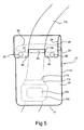
- the casing 20 comprises a pliable sheet 50 configured to be folded around the seat belt buckle 120, wherein a gap 30 between respective edges thereof forms an aperture to receive the seat belt strap 110 and the insert 112.
- the pliable sheet 50 can have a slit or slot (not shown) therein configured to receive the seat belt strap and the insert 112.
- the pliable sheet 50 is provided with a pair of opposing side wings 52 which are arranged to be folded towards one another thereby substantially forming a sleeve 22' around the seat belt buckle 120, and a flap member 54 which is arranged to be folded over an open upper end 23' of the sleeve 22' so formed, thereby substantially encasing the seat belt buckle 120 as shown in Figure 6 .
- the pliable sheet 50 is formed from a pliable material which can be easily bent into a desired shape and retain said desired shape.
- pliable materials include, but are not limited to, a moldable plastics material, a moldable synthetic rubber, a moldable composite material, a malleable metallic or malleable alloy material, such as, for example, a wire mesh material.
- the opposing side wings 52 and/or the flap member 54 of the pliable sheet 50 may be quickly forced apart or folded back, thereby deforming the casing 20.
Landscapes
- Engineering & Computer Science (AREA)
- Aviation & Aerospace Engineering (AREA)
- Automotive Seat Belt Assembly (AREA)
- Portable Nailing Machines And Staplers (AREA)
- Yarns And Mechanical Finishing Of Yarns Or Ropes (AREA)
- Ropes Or Cables (AREA)
- Buckles (AREA)
Claims (11)
- Dispositif de sécurité (10) pour une boucle de ceinture de sécurité (120) agencé, durant l'utilisation, pour empêcher d'appuyer sur un bouton de libération (122) de la boucle de ceinture de sécurité (120) et ainsi d'en séparer une partie d'insertion (112) couplée avec une courroie de ceinture de sécurité (110), le dispositif de sécurité (10) comprenant un boîtier (12) pour la boucle de ceinture de sécurité (120), caractérisé en ce que le boîtier (12) est formé à partir d'une feuille pliée comportant une section allongée (76) avec des parties latérales opposées configurées pour se plier autour de la boucle de ceinture de sécurité (120), un élément de rabat (24) dépendant d'un côté de la section allongée (76), dans lequel est disposée une ouverture (33) dans l'élément de rabat (24), l'ouverture (33) comprenant une fente ou une encoche pour recevoir la partie d'insertion.
- Dispositif de sécurité selon la revendication 1, dans lequel le boîtier (12) est déformable entre une configuration pliée et une configuration dépliée.
- Dispositif de sécurité selon la revendication 1 ou la revendication 2, dans lequel le boîtier (12) comprend un manchon (22) comportant une extrémité inférieure ouverte (21) et une extrémité supérieure ouverte (23) et l'élément de rabat (24) est configuré, durant l'utilisation, pour être plié par-dessus l'extrémité supérieure ouverte (23) du manchon.
- Dispositif de sécurité selon une quelconque des revendications 1 à 3, dans lequel les parties latérales opposées de la section allongée (76) sont espacées suffisamment près l'une de l'autre pour être jointes à des attaches libérables respectives.
- Dispositif de sécurité selon la revendication 4, dans lequel le type d'attache est sélectionné pour permettre aux parties latérales opposées de la section allongée (76) d'être facilement détachées l'une de l'autre.
- Dispositif de sécurité selon une quelconque des revendications 1 à 5, dans lequel la fente ou l'encoche (33) est disposée transversalement dans l'élément de rabat (24).
- Dispositif de sécurité selon une quelconque des revendications 1 à 6, dans lequel l'élément de rabat (24) est pourvu d'une attache (26) pour fixer l'élément de rabat plié par-dessus la section allongée pliée.
- Dispositif de sécurité selon une quelconque des revendications 1 à 7, dans lequel l'élément de rabat (24) est pourvu d'un élément de renforcement disposé, durant l'utilisation, de façon proximale au bouton de libération (122).
- Dispositif de sécurité selon une quelconque des revendications 1 à 8, dans lequel l'élément de rabat est pourvu de parties d'aile latérales opposées (73a, 73b) configurées, durant l'utilisation, pour être pliées l'une vers l'autre et autour de la boucle de ceinture de sécurité (120) lorsque l'élément de rabat (24) est plié par-dessus la section allongée pliée (76).
- Dispositif de sécurité selon la revendication 9, dans lequel les parties d'aile latérales opposées (73a, 73b) sont pourvues d'attaches (80b) pour entrer en prise avec une attache correspondante (80a) disposée sur une surface extérieure du manchon (22) du boîtier (12).
- Dispositif de sécurité selon une quelconque des revendications 1 à 10, dans lequel la section allongée (76) et l'élément de rabat (24) sont formés à partir d'un matériau flexible qui peut être plié en une forme souhaitée et est capable de garder ladite forme souhaitée.
Applications Claiming Priority (2)
| Application Number | Priority Date | Filing Date | Title |
|---|---|---|---|
| AU2005902393A AU2005902393A0 (en) | 2005-05-12 | Safety device for a seat belt buckle | |
| PCT/AU2006/000631 WO2006119579A1 (fr) | 2005-05-12 | 2006-05-12 | Dispositif de securite pour boucle de ceinture de siege |
Publications (3)
| Publication Number | Publication Date |
|---|---|
| EP1879667A1 EP1879667A1 (fr) | 2008-01-23 |
| EP1879667A4 EP1879667A4 (fr) | 2009-06-17 |
| EP1879667B1 true EP1879667B1 (fr) | 2010-07-28 |
Family
ID=37396112
Family Applications (1)
| Application Number | Title | Priority Date | Filing Date |
|---|---|---|---|
| EP06721505A Not-in-force EP1879667B1 (fr) | 2005-05-12 | 2006-05-12 | Dispositif de securite pour boucle de ceinture de siege |
Country Status (8)
| Country | Link |
|---|---|
| US (1) | US20080179936A1 (fr) |
| EP (1) | EP1879667B1 (fr) |
| JP (1) | JP2008540220A (fr) |
| CN (1) | CN101189046A (fr) |
| AT (1) | ATE475458T1 (fr) |
| CA (1) | CA2607480A1 (fr) |
| DE (1) | DE602006015799D1 (fr) |
| WO (1) | WO2006119579A1 (fr) |
Families Citing this family (14)
| Publication number | Priority date | Publication date | Assignee | Title |
|---|---|---|---|---|
| EP2358230B1 (fr) * | 2008-11-24 | 2013-07-17 | Holmbergs Childsafety Holding AB | Boucle de ceinture de sécurité et ensemble pour siège d'enfant de véhicule |
| JP4784645B2 (ja) * | 2008-12-26 | 2011-10-05 | トヨタ自動車株式会社 | 車両用乗員拘束装置 |
| AU2010214645A1 (en) * | 2009-08-26 | 2011-03-17 | Shuan Therese Pereira | Cover |
| US8393061B2 (en) | 2010-08-16 | 2013-03-12 | William McGlynn | Seat belt safety device |
| FR2969978B1 (fr) * | 2010-12-29 | 2012-12-21 | Renault Sa | Gache d'accrochage d'une ceinture de securite comportant un volet de protection et volet de protection pour une telle gache |
| JP2012218720A (ja) * | 2011-04-04 | 2012-11-12 | Machiko Ikenoue | 誤操作防止用バックルカバー |
| US20140001816A1 (en) * | 2012-06-28 | 2014-01-02 | Stephen Joseph Dorriety | High chair strap safety release |
| US9199604B1 (en) * | 2014-08-11 | 2015-12-01 | Walter J. Phillips | Alert cover for seatbelt |
| US9439479B1 (en) * | 2014-08-29 | 2016-09-13 | Phuong Anh T. Vu | Seat belt reminder cover |
| US9908502B2 (en) * | 2015-10-05 | 2018-03-06 | Ayenew Marew | Belt pro |
| WO2017201160A1 (fr) | 2016-05-17 | 2017-11-23 | Unger Natalie Beth | Procédés et systèmes pour décorer des sièges de sécurité |
| CN106825361B (zh) * | 2017-01-12 | 2019-01-18 | 昆山钰立电子科技股份有限公司 | 一种波音飞机搭扣制备工艺 |
| KR102570363B1 (ko) * | 2022-01-19 | 2023-08-25 | 주식회사 박앤웍스 | 안전벨트 버클 설치용 차량 방향제 키트 |
| US11864633B2 (en) * | 2022-05-09 | 2024-01-09 | Dolores Moody | Seatbelt buckle cover |
Family Cites Families (16)
| Publication number | Priority date | Publication date | Assignee | Title |
|---|---|---|---|---|
| US5009346A (en) * | 1988-11-21 | 1991-04-23 | Peace River Arms & Accessories, Inc. | Sling mountable pouch for firearms |
| US4939824A (en) * | 1989-08-11 | 1990-07-10 | Reed Delores A | Vehicle safety belt buckle cover |
| JPH0523914U (ja) * | 1991-02-26 | 1993-03-30 | 日本精工株式会社 | シートベルト用バツクル |
| US5332093A (en) * | 1993-02-12 | 1994-07-26 | Fred Littlepage | Mailbox shaped doll and accessory carrier and blank therefore |
| SE502519C2 (sv) * | 1994-03-23 | 1995-11-06 | Marianne Hansson | Anordning vid fordon |
| US5482324A (en) * | 1994-10-17 | 1996-01-09 | Gardiner; Linda J. | Supplemental car seat belt for protecting users wtih stomas |
| US5611470A (en) * | 1995-03-01 | 1997-03-18 | Vias; Pamela S. | Tamper resistant pouch for child security device |
| US6142575A (en) * | 1999-02-11 | 2000-11-07 | Quaker State Investment Company | Safety belt adjuster |
| GB2348460A (en) * | 1999-03-27 | 2000-10-04 | Deborah Louise Edwards | Harness buckle safety device |
| US6041480A (en) * | 1999-04-16 | 2000-03-28 | White; Paula | Seat belt lock cover |
| DE20002899U1 (de) * | 2000-02-17 | 2000-07-13 | Schorz Wolfgang | Kindersicherung für Gurtschloss in Kfz |
| DE60111140T2 (de) * | 2000-08-25 | 2006-03-16 | Kyozo Kobayashi | Sicherheitsgurtdecke |
| GB2371830B (en) * | 2001-02-03 | 2005-04-06 | David Anderson Hope | Accessory for safety harnesses |
| DE10304712B4 (de) * | 2003-02-06 | 2006-02-09 | Daimlerchrysler Ag | Steckzunge |
| US7165294B2 (en) * | 2004-01-22 | 2007-01-23 | Christopher Surdam | Strap sack |
| US20070086182A1 (en) * | 2005-10-14 | 2007-04-19 | Kelly Lee A | Horse safety headlight apparatus |
-
2006
- 2006-05-12 EP EP06721505A patent/EP1879667B1/fr not_active Not-in-force
- 2006-05-12 DE DE602006015799T patent/DE602006015799D1/de active Active
- 2006-05-12 CN CN200680020063.7A patent/CN101189046A/zh active Pending
- 2006-05-12 US US11/913,978 patent/US20080179936A1/en not_active Abandoned
- 2006-05-12 AT AT06721505T patent/ATE475458T1/de not_active IP Right Cessation
- 2006-05-12 CA CA002607480A patent/CA2607480A1/fr not_active Abandoned
- 2006-05-12 WO PCT/AU2006/000631 patent/WO2006119579A1/fr not_active Application Discontinuation
- 2006-05-12 JP JP2008510365A patent/JP2008540220A/ja not_active Ceased
Also Published As
| Publication number | Publication date |
|---|---|
| DE602006015799D1 (de) | 2010-09-09 |
| JP2008540220A (ja) | 2008-11-20 |
| EP1879667A4 (fr) | 2009-06-17 |
| CN101189046A (zh) | 2008-05-28 |
| WO2006119579A1 (fr) | 2006-11-16 |
| ATE475458T1 (de) | 2010-08-15 |
| EP1879667A1 (fr) | 2008-01-23 |
| US20080179936A1 (en) | 2008-07-31 |
| CA2607480A1 (fr) | 2006-11-16 |
Similar Documents
| Publication | Publication Date | Title |
|---|---|---|
| EP1879667B1 (fr) | Dispositif de securite pour boucle de ceinture de siege | |
| US4961251A (en) | Flexible safety belt buckle guard | |
| US4939824A (en) | Vehicle safety belt buckle cover | |
| US6138331A (en) | Release resistant seat belt buckle cover | |
| EP2258583B1 (fr) | Ensemble de siège de sécurité pour enfants avec un dispositif de positionnement de boucle | |
| JP3454713B2 (ja) | ベルト連結具 | |
| US5730498A (en) | Quick release closure assembly | |
| JP5643281B2 (ja) | 車両用チャイルドシート及びハーネスカバー | |
| US20100301594A1 (en) | Guide Assembly for a Safety Belt | |
| CA2462032A1 (fr) | Couvre-siege d'enfant | |
| JP5643282B2 (ja) | 車両用チャイルドシート及びショルダーパッド | |
| US7918502B2 (en) | Apparatus and method for attaching a child car seat to luggage | |
| JP2671969B2 (ja) | 乗物用安全装置及び安全装置用のタング・アセンブリ | |
| US20070289111A1 (en) | Security cover for a restraint buckle | |
| US7093905B1 (en) | Threading device for installing a child's car seat | |
| US6269991B1 (en) | Strap system and method for making same | |
| US6832775B1 (en) | Trailer hitch cushion | |
| US7011375B1 (en) | Apparatus and method to assist seat belt engagement | |
| AU2006246318A1 (en) | Safety device for a seat belt buckle | |
| US6783185B1 (en) | Bib for attachment to a seat belt | |
| GB2371830A (en) | Cover for safety harnesses | |
| GB2365916A (en) | Hook and tether strap length adjuster | |
| GB2045333A (en) | Luggage closure | |
| US10479317B1 (en) | Apparatus and method for seat belt wrap | |
| US10471928B2 (en) | Safety device for use with a safety harness |
Legal Events
| Date | Code | Title | Description |
|---|---|---|---|
| PUAI | Public reference made under article 153(3) epc to a published international application that has entered the european phase |
Free format text: ORIGINAL CODE: 0009012 |
|
| 17P | Request for examination filed |
Effective date: 20071121 |
|
| AK | Designated contracting states |
Kind code of ref document: A1 Designated state(s): AT BE BG CH CY CZ DE DK EE ES FI FR GB GR HU IE IS IT LI LT LU LV MC NL PL PT RO SE SI SK TR |
|
| DAX | Request for extension of the european patent (deleted) | ||
| A4 | Supplementary search report drawn up and despatched |
Effective date: 20090519 |
|
| 17Q | First examination report despatched |
Effective date: 20090825 |
|
| GRAP | Despatch of communication of intention to grant a patent |
Free format text: ORIGINAL CODE: EPIDOSNIGR1 |
|
| GRAS | Grant fee paid |
Free format text: ORIGINAL CODE: EPIDOSNIGR3 |
|
| GRAA | (expected) grant |
Free format text: ORIGINAL CODE: 0009210 |
|
| AK | Designated contracting states |
Kind code of ref document: B1 Designated state(s): AT BE BG CH CY CZ DE DK EE ES FI FR GB GR HU IE IS IT LI LT LU LV MC NL PL PT RO SE SI SK TR |
|
| REG | Reference to a national code |
Ref country code: GB Ref legal event code: FG4D |
|
| REG | Reference to a national code |
Ref country code: CH Ref legal event code: EP |
|
| REG | Reference to a national code |
Ref country code: IE Ref legal event code: FG4D |
|
| REF | Corresponds to: |
Ref document number: 602006015799 Country of ref document: DE Date of ref document: 20100909 Kind code of ref document: P |
|
| REG | Reference to a national code |
Ref country code: NL Ref legal event code: VDEP Effective date: 20100728 |
|
| LTIE | Lt: invalidation of european patent or patent extension |
Effective date: 20100728 |
|
| PG25 | Lapsed in a contracting state [announced via postgrant information from national office to epo] |
Ref country code: AT Free format text: LAPSE BECAUSE OF FAILURE TO SUBMIT A TRANSLATION OF THE DESCRIPTION OR TO PAY THE FEE WITHIN THE PRESCRIBED TIME-LIMIT Effective date: 20100728 Ref country code: NL Free format text: LAPSE BECAUSE OF FAILURE TO SUBMIT A TRANSLATION OF THE DESCRIPTION OR TO PAY THE FEE WITHIN THE PRESCRIBED TIME-LIMIT Effective date: 20100728 Ref country code: LT Free format text: LAPSE BECAUSE OF FAILURE TO SUBMIT A TRANSLATION OF THE DESCRIPTION OR TO PAY THE FEE WITHIN THE PRESCRIBED TIME-LIMIT Effective date: 20100728 Ref country code: FI Free format text: LAPSE BECAUSE OF FAILURE TO SUBMIT A TRANSLATION OF THE DESCRIPTION OR TO PAY THE FEE WITHIN THE PRESCRIBED TIME-LIMIT Effective date: 20100728 |
|
| PG25 | Lapsed in a contracting state [announced via postgrant information from national office to epo] |
Ref country code: SI Free format text: LAPSE BECAUSE OF FAILURE TO SUBMIT A TRANSLATION OF THE DESCRIPTION OR TO PAY THE FEE WITHIN THE PRESCRIBED TIME-LIMIT Effective date: 20100728 Ref country code: PT Free format text: LAPSE BECAUSE OF FAILURE TO SUBMIT A TRANSLATION OF THE DESCRIPTION OR TO PAY THE FEE WITHIN THE PRESCRIBED TIME-LIMIT Effective date: 20101129 Ref country code: PL Free format text: LAPSE BECAUSE OF FAILURE TO SUBMIT A TRANSLATION OF THE DESCRIPTION OR TO PAY THE FEE WITHIN THE PRESCRIBED TIME-LIMIT Effective date: 20100728 Ref country code: IS Free format text: LAPSE BECAUSE OF FAILURE TO SUBMIT A TRANSLATION OF THE DESCRIPTION OR TO PAY THE FEE WITHIN THE PRESCRIBED TIME-LIMIT Effective date: 20101128 Ref country code: CY Free format text: LAPSE BECAUSE OF FAILURE TO SUBMIT A TRANSLATION OF THE DESCRIPTION OR TO PAY THE FEE WITHIN THE PRESCRIBED TIME-LIMIT Effective date: 20100728 Ref country code: BG Free format text: LAPSE BECAUSE OF FAILURE TO SUBMIT A TRANSLATION OF THE DESCRIPTION OR TO PAY THE FEE WITHIN THE PRESCRIBED TIME-LIMIT Effective date: 20101028 |
|
| PG25 | Lapsed in a contracting state [announced via postgrant information from national office to epo] |
Ref country code: GR Free format text: LAPSE BECAUSE OF FAILURE TO SUBMIT A TRANSLATION OF THE DESCRIPTION OR TO PAY THE FEE WITHIN THE PRESCRIBED TIME-LIMIT Effective date: 20101029 Ref country code: SE Free format text: LAPSE BECAUSE OF FAILURE TO SUBMIT A TRANSLATION OF THE DESCRIPTION OR TO PAY THE FEE WITHIN THE PRESCRIBED TIME-LIMIT Effective date: 20100728 Ref country code: BE Free format text: LAPSE BECAUSE OF FAILURE TO SUBMIT A TRANSLATION OF THE DESCRIPTION OR TO PAY THE FEE WITHIN THE PRESCRIBED TIME-LIMIT Effective date: 20100728 Ref country code: LV Free format text: LAPSE BECAUSE OF FAILURE TO SUBMIT A TRANSLATION OF THE DESCRIPTION OR TO PAY THE FEE WITHIN THE PRESCRIBED TIME-LIMIT Effective date: 20100728 |
|
| PG25 | Lapsed in a contracting state [announced via postgrant information from national office to epo] |
Ref country code: DK Free format text: LAPSE BECAUSE OF FAILURE TO SUBMIT A TRANSLATION OF THE DESCRIPTION OR TO PAY THE FEE WITHIN THE PRESCRIBED TIME-LIMIT Effective date: 20100728 |
|
| PG25 | Lapsed in a contracting state [announced via postgrant information from national office to epo] |
Ref country code: EE Free format text: LAPSE BECAUSE OF FAILURE TO SUBMIT A TRANSLATION OF THE DESCRIPTION OR TO PAY THE FEE WITHIN THE PRESCRIBED TIME-LIMIT Effective date: 20100728 Ref country code: IT Free format text: LAPSE BECAUSE OF FAILURE TO SUBMIT A TRANSLATION OF THE DESCRIPTION OR TO PAY THE FEE WITHIN THE PRESCRIBED TIME-LIMIT Effective date: 20100728 Ref country code: CZ Free format text: LAPSE BECAUSE OF FAILURE TO SUBMIT A TRANSLATION OF THE DESCRIPTION OR TO PAY THE FEE WITHIN THE PRESCRIBED TIME-LIMIT Effective date: 20100728 Ref country code: RO Free format text: LAPSE BECAUSE OF FAILURE TO SUBMIT A TRANSLATION OF THE DESCRIPTION OR TO PAY THE FEE WITHIN THE PRESCRIBED TIME-LIMIT Effective date: 20100728 Ref country code: SK Free format text: LAPSE BECAUSE OF FAILURE TO SUBMIT A TRANSLATION OF THE DESCRIPTION OR TO PAY THE FEE WITHIN THE PRESCRIBED TIME-LIMIT Effective date: 20100728 |
|
| PLBE | No opposition filed within time limit |
Free format text: ORIGINAL CODE: 0009261 |
|
| STAA | Information on the status of an ep patent application or granted ep patent |
Free format text: STATUS: NO OPPOSITION FILED WITHIN TIME LIMIT |
|
| PG25 | Lapsed in a contracting state [announced via postgrant information from national office to epo] |
Ref country code: ES Free format text: LAPSE BECAUSE OF FAILURE TO SUBMIT A TRANSLATION OF THE DESCRIPTION OR TO PAY THE FEE WITHIN THE PRESCRIBED TIME-LIMIT Effective date: 20101108 |
|
| 26N | No opposition filed |
Effective date: 20110429 |
|
| PGFP | Annual fee paid to national office [announced via postgrant information from national office to epo] |
Ref country code: FR Payment date: 20110524 Year of fee payment: 6 |
|
| REG | Reference to a national code |
Ref country code: DE Ref legal event code: R097 Ref document number: 602006015799 Country of ref document: DE Effective date: 20110429 |
|
| PGFP | Annual fee paid to national office [announced via postgrant information from national office to epo] |
Ref country code: GB Payment date: 20110523 Year of fee payment: 6 |
|
| PGFP | Annual fee paid to national office [announced via postgrant information from national office to epo] |
Ref country code: DE Payment date: 20110624 Year of fee payment: 6 |
|
| PG25 | Lapsed in a contracting state [announced via postgrant information from national office to epo] |
Ref country code: MC Free format text: LAPSE BECAUSE OF NON-PAYMENT OF DUE FEES Effective date: 20110531 |
|
| REG | Reference to a national code |
Ref country code: CH Ref legal event code: PL |
|
| PG25 | Lapsed in a contracting state [announced via postgrant information from national office to epo] |
Ref country code: LI Free format text: LAPSE BECAUSE OF NON-PAYMENT OF DUE FEES Effective date: 20110531 Ref country code: CH Free format text: LAPSE BECAUSE OF NON-PAYMENT OF DUE FEES Effective date: 20110531 |
|
| REG | Reference to a national code |
Ref country code: IE Ref legal event code: MM4A |
|
| PG25 | Lapsed in a contracting state [announced via postgrant information from national office to epo] |
Ref country code: IE Free format text: LAPSE BECAUSE OF NON-PAYMENT OF DUE FEES Effective date: 20110512 |
|
| GBPC | Gb: european patent ceased through non-payment of renewal fee |
Effective date: 20120512 |
|
| REG | Reference to a national code |
Ref country code: FR Ref legal event code: ST Effective date: 20130131 |
|
| REG | Reference to a national code |
Ref country code: DE Ref legal event code: R119 Ref document number: 602006015799 Country of ref document: DE Effective date: 20121201 |
|
| PG25 | Lapsed in a contracting state [announced via postgrant information from national office to epo] |
Ref country code: GB Free format text: LAPSE BECAUSE OF NON-PAYMENT OF DUE FEES Effective date: 20120512 Ref country code: FR Free format text: LAPSE BECAUSE OF NON-PAYMENT OF DUE FEES Effective date: 20120531 |
|
| PG25 | Lapsed in a contracting state [announced via postgrant information from national office to epo] |
Ref country code: LU Free format text: LAPSE BECAUSE OF NON-PAYMENT OF DUE FEES Effective date: 20110512 |
|
| PG25 | Lapsed in a contracting state [announced via postgrant information from national office to epo] |
Ref country code: DE Free format text: LAPSE BECAUSE OF NON-PAYMENT OF DUE FEES Effective date: 20121201 |
|
| PG25 | Lapsed in a contracting state [announced via postgrant information from national office to epo] |
Ref country code: TR Free format text: LAPSE BECAUSE OF FAILURE TO SUBMIT A TRANSLATION OF THE DESCRIPTION OR TO PAY THE FEE WITHIN THE PRESCRIBED TIME-LIMIT Effective date: 20100728 |
|
| PG25 | Lapsed in a contracting state [announced via postgrant information from national office to epo] |
Ref country code: HU Free format text: LAPSE BECAUSE OF FAILURE TO SUBMIT A TRANSLATION OF THE DESCRIPTION OR TO PAY THE FEE WITHIN THE PRESCRIBED TIME-LIMIT Effective date: 20100728 |