EP1878600A2 - Fensterrollo eines Fahrzeugseitenfensters - Google Patents
Fensterrollo eines Fahrzeugseitenfensters Download PDFInfo
- Publication number
- EP1878600A2 EP1878600A2 EP07012606A EP07012606A EP1878600A2 EP 1878600 A2 EP1878600 A2 EP 1878600A2 EP 07012606 A EP07012606 A EP 07012606A EP 07012606 A EP07012606 A EP 07012606A EP 1878600 A2 EP1878600 A2 EP 1878600A2
- Authority
- EP
- European Patent Office
- Prior art keywords
- roller blind
- spring
- roller
- window
- carriage
- Prior art date
- Legal status (The legal status is an assumption and is not a legal conclusion. Google has not performed a legal analysis and makes no representation as to the accuracy of the status listed.)
- Granted
Links
Images

Classifications
-
- B—PERFORMING OPERATIONS; TRANSPORTING
- B60—VEHICLES IN GENERAL
- B60J—WINDOWS, WINDSCREENS, NON-FIXED ROOFS, DOORS, OR SIMILAR DEVICES FOR VEHICLES; REMOVABLE EXTERNAL PROTECTIVE COVERINGS SPECIALLY ADAPTED FOR VEHICLES
- B60J1/00—Windows; Windscreens; Accessories therefor
- B60J1/20—Accessories, e.g. wind deflectors, blinds
- B60J1/2011—Blinds; curtains or screens reducing heat or light intensity
- B60J1/2013—Roller blinds
- B60J1/2036—Roller blinds characterised by structural elements
- B60J1/2061—Tensioning systems for keeping the blind taut when in use, other than spring motors
-
- B—PERFORMING OPERATIONS; TRANSPORTING
- B60—VEHICLES IN GENERAL
- B60J—WINDOWS, WINDSCREENS, NON-FIXED ROOFS, DOORS, OR SIMILAR DEVICES FOR VEHICLES; REMOVABLE EXTERNAL PROTECTIVE COVERINGS SPECIALLY ADAPTED FOR VEHICLES
- B60J1/00—Windows; Windscreens; Accessories therefor
- B60J1/20—Accessories, e.g. wind deflectors, blinds
- B60J1/2011—Blinds; curtains or screens reducing heat or light intensity
- B60J1/2013—Roller blinds
- B60J1/2019—Roller blinds powered, e.g. by electric, hydraulic or pneumatic actuators
- B60J1/2027—Roller blinds powered, e.g. by electric, hydraulic or pneumatic actuators with a buckle-proof guided flexible actuating element acting on the draw bar for pushing or push-pulling, e.g. a Bowden cable
-
- B—PERFORMING OPERATIONS; TRANSPORTING
- B60—VEHICLES IN GENERAL
- B60J—WINDOWS, WINDSCREENS, NON-FIXED ROOFS, DOORS, OR SIMILAR DEVICES FOR VEHICLES; REMOVABLE EXTERNAL PROTECTIVE COVERINGS SPECIALLY ADAPTED FOR VEHICLES
- B60J1/00—Windows; Windscreens; Accessories therefor
- B60J1/20—Accessories, e.g. wind deflectors, blinds
- B60J1/2011—Blinds; curtains or screens reducing heat or light intensity
- B60J1/2013—Roller blinds
- B60J1/2036—Roller blinds characterised by structural elements
- B60J1/2044—Draw bars, including elements attached to it, e.g. sliding shoes, gripping elements or pull cords
-
- B—PERFORMING OPERATIONS; TRANSPORTING
- B60—VEHICLES IN GENERAL
- B60J—WINDOWS, WINDSCREENS, NON-FIXED ROOFS, DOORS, OR SIMILAR DEVICES FOR VEHICLES; REMOVABLE EXTERNAL PROTECTIVE COVERINGS SPECIALLY ADAPTED FOR VEHICLES
- B60J1/00—Windows; Windscreens; Accessories therefor
- B60J1/20—Accessories, e.g. wind deflectors, blinds
- B60J1/2011—Blinds; curtains or screens reducing heat or light intensity
- B60J1/2013—Roller blinds
- B60J1/2036—Roller blinds characterised by structural elements
- B60J1/2058—Springs for compensating the number of windings of the blind on the tube in case winding tube and draw bar are driven together
-
- B—PERFORMING OPERATIONS; TRANSPORTING
- B60—VEHICLES IN GENERAL
- B60J—WINDOWS, WINDSCREENS, NON-FIXED ROOFS, DOORS, OR SIMILAR DEVICES FOR VEHICLES; REMOVABLE EXTERNAL PROTECTIVE COVERINGS SPECIALLY ADAPTED FOR VEHICLES
- B60J1/00—Windows; Windscreens; Accessories therefor
- B60J1/20—Accessories, e.g. wind deflectors, blinds
- B60J1/2011—Blinds; curtains or screens reducing heat or light intensity
- B60J1/2013—Roller blinds
- B60J1/2066—Arrangement of blinds in vehicles
- B60J1/2075—Arrangement of blinds in vehicles specially adapted for fixed windows
-
- B—PERFORMING OPERATIONS; TRANSPORTING
- B60—VEHICLES IN GENERAL
- B60J—WINDOWS, WINDSCREENS, NON-FIXED ROOFS, DOORS, OR SIMILAR DEVICES FOR VEHICLES; REMOVABLE EXTERNAL PROTECTIVE COVERINGS SPECIALLY ADAPTED FOR VEHICLES
- B60J1/00—Windows; Windscreens; Accessories therefor
- B60J1/20—Accessories, e.g. wind deflectors, blinds
- B60J1/2011—Blinds; curtains or screens reducing heat or light intensity
- B60J1/2013—Roller blinds
- B60J1/2066—Arrangement of blinds in vehicles
- B60J1/2086—Arrangement of blinds in vehicles specially adapted for openable windows, e.g. side window
Definitions
- the invention relates to a window blind of a vehicle side window according to the preamble of claim 1.
- roller blind Such a thing DE 10 2004 049 167 A1 ( EP 1 645 448 A1 ) known roller blind has a roller blind, which can be used to cover the vehicle side window for covering the vehicle window by a roller blind shaft, which is arranged in the vicinity of the lower window boundary, unwound.
- a roller blind shaft which is arranged in the vicinity of the lower window boundary, unwound.
- a pull-out roller blind end which may be rigid in the form of an extension rod, a pull-out force.
- This pull-out force is transmitted to the roller blind end via at least one carriage guided in the direction of movement along the roller blind, which carriage is driven by a drive device.
- a pull-in force is exerted on the driven roller shaft.
- the guide path along which the at least one carriage is guided driven by the drive means is limited at its upper end and at its lower end by predetermined dimensions on the vehicle in the region of the upper and lower edges of the window. This can lead to an open gap remaining between the upper window boundary edge and the extended roller blind end. Furthermore, when fully wound on the roller blind roller blind the extendable roller blind end over the lower window boundary edge still survive slightly.
- the object of the invention is to provide a window blind of the type mentioned, in which a complete covering of the side window when the runway and a supernatant-free winding of the blind is achieved on the roller blind.
- the extendable roller blind end is mounted resiliently in the direction of the pull-in force and pull-out force in the carriage.
- the spring provided for this purpose between the roller blind end and the carriage acts on the rolled-up roller against the retraction force transmitted via the roller shaft as a resilient compression spring which is compressed when the roller blind is completely wound up and, when the roller blind is completely unwound, exerts an additional extension movement in the uppermost carriage position on the roller blind end, with the additional pull-out movement can be limited by the upper window limit.
- the spring is formed as a cylindrical coil spring.
- a surrounding the spring circumference pot whose interior is adapted to the cylindrical spring circumference and a projecting into the spring interior guide pin, which is also adapted to the cylindrical spring interior on its outer surface.
- the retaining pin may be attached to a bearing on which the roller blind end is mounted, and the pot on the carriage. It is also the reverse arrangement possible, in which the pot are provided on the bearing of the roller blind end and the retaining pin on the carriage.
- a resilient biasing force which ensures the unwinding and winding of the roller blind for a firm guidance of the blind.
- a resilient biasing force is off DE 10 2004 049 167 A1 ( EP 1 645 448 A1 ) known.
- the roller shaft can be slidably mounted along its shaft axis, so that a perfect, wrinkle-free winding and unwinding of the roller blind is achieved even with different roller blind widths in pullout or feed.
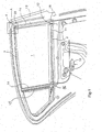
- the embodiment shown in FIG. 1 has a roller blind 1, which can be wound onto a roller shaft 2 and can be unwound from the roller shaft 2.
- the roller blind 1 is unwound from the roller shaft 2 and a pull-out roller blind end 3 is located at an upper window boundary edge of a vehicle side window. In this position, the vehicle window is completely covered by the blind sheet 1.
- the extendable roller blind end 3 is formed in a known manner as an extension rod, whereby the roller blind end 3 is formed substantially rigid over the entire width of the blind sheet 1.
- the extendable roller blind end 3 is mounted on its two sides in slide 4.
- the connection between the Roller blind end 3 and one of the two slides 4 (on the right side of the blind sheet 1) is shown in an enlarged view in FIG.
- the carriages 4 are guided in slide guides 14 which extend in roller blind movement directions.
- the carriage 4 is connected in this embodiment with an upper end of a drive transmission means, for example a brush cable 15 or 17.
- the extendable roller blind end 3 is pivotally mounted in a bearing 8.
- the bearing 8 is supported on the carriage 4 via a spring 5, which is formed in the embodiment as a cylindrical coil spring, movable.
- the direction of movement of the bearing 8 and thus of the roller blind end 3 relative to the carriage 4 corresponds to the pullout or retraction direction of the roller blind 1.
- the direction of movement of the bearing 8 relative to the carriage 4 is in the embodiment shown in FIG. 2 by a guide device with which also the direction of movement of the spring 5 is determined determined.
- a mounted on the carriage 4 pot 6 is provided, in which the spring 5 is arranged.
- the interior of the pot is adapted to the outer cylindrical spring circumference.
- the spring 5 which is designed as a cylindrical helical spring arranged.
- the cylindrical coil spring is supported at the upper end of the bearing pin 7, for example, on a holder 13 of the bearing pin 7 and at its lower end at the bottom of the pot 6.
- the roller blind 3. is pivotally mounted in the bearing 8. For linear movement guidance of the bearing 8 on the carriage 4 can still be provided a separate linear guide.
- Such a connection between the carriage 4 and the roller blind end 3 may be provided on both sides of the roller blind end 3.
- the forces required to extend and retract the roller blind 1 are provided by a drive device 10, for example an electric DC motor educated.
- the drive torque of the drive device 10 is transmitted to a gear 16 via a brush cable or a similarly acting flexible push / pull element, for example punched tape.
- the gear 16 may be formed as a worm or bevel gear, from which a worm or bevel gear rotatably seated on a drive shaft 11 which extends through a cavity of the roller shaft 2 itself.
- the gear 16 is provided at the left end of the drive shaft 11. On the right, projecting beyond the roller shaft 2 shaft end is located in a second brush cable 17 or similarly acting push / pull element engaging drive wheel 18.
- the drive wheel 18 is rotatably connected to the drive shaft 11.
- a resilient compensation device 12 which generates a resilient bias between the brush cable and connected to an upper brush cable end 20 carriage 4 and the roller shaft 2.
- this resilient bias when pulling out and pulling the roller blind 1, this creates the roller blind smoothing bias.
- a compensation of the changing winding diameter of the wound on the roller shaft 2 roller blind is thereby achieved.
- the right slide 4 is connected to the brush cable 17 and the left slide 4 to the brush cable 15.
- the connection with the upper brush cable ends 20 takes place in the manner shown, for example, in FIG. 2.
- the bus cables and cables or other known per se drive forms US 6,086,133
- the drive device 14 is rotated in the direction opposite to the extension direction, so that by means of the brush cables 15 and 17, the carriage 4 are moved back to the lower positions.
- the roller shaft 2 is rotated in the web direction, so that a pull-in force is exerted on the roller blind 1 of the roller shaft 2.
- the carriages 4 are moved into their lower end positions in their slide guides 14.
- the retraction force mediated by the roller shaft 2 continues to act on the roller blind 1, the springs 5 acting as resilient compression springs and are compressed at the complete retraction of the roller blind end 3 under the lower window boundary edge.
Landscapes
- Engineering & Computer Science (AREA)
- Mechanical Engineering (AREA)
- Operating, Guiding And Securing Of Roll- Type Closing Members (AREA)
Abstract
Description
- Die Erfindung betrifft ein Fensterrollo eines Fahrzeugseitenfensters nach dem Oberbegriff des Patentanspruches 1.
- Ein derartiges aus
DE 10 2004 049 167 A1 (EP 1 645 448 A1 ) bekanntes Fensterrollo besitzt eine Rollobahn, welche zum Abdecken des Fahrzeugseitenfensters zum Bedecken des Fahrzeugfensters von einer Rollowelle, welche in der Nähe der unteren Fensterbegrenzung angeordnet ist, abgewickelt werden kann. Hierzu wirkt an einem ausziehbaren Rollobahnende, welches in Form eines Auszugstabs starr ausgebildet sein kann, eine Auszugskraft. Diese Auszugskraft wird über wenigstens einen entlang der Rollobahn in Bewegungsrichtung geführten Schlitten, welcher von einer Antriebseinrichtung angetrieben wird, auf das Rollobahnende übertragen. Zum Aufwickeln der Rollobahn auf die Rollowelle wird über die angetriebene Rollowelle eine Einzugskraft ausgeübt. Die Führungsstrecke, entlang welcher der wenigstens eine Schlitten von der Antriebseinrichtung angetrieben geführt wird, ist an ihrem oberen Ende und an ihrem unteren Ende durch am Fahrzeug vorgegebene Abmessungen im Bereich der oberen und unteren Fensterkanten begrenzt. Dies kann dazu führen, dass zwischen der oberen Fensterbegrenzungskante und dem ausgezogenen Rollobahnende ein offener Spalt verbleibt. Ferner kann bei vollständig auf der Rollowelle aufgewickelter Rollobahn das ausziehbare Rollobahnende über der unteren Fensterbegrenzungskante noch geringfügig überstehen. - Aufgabe der Erfindung ist es, ein Fensterrollo der eingangs genannten Art zu schaffen, bei welchem ein vollständiges Abdecken des Seitenfensters bei ausgezogener Rollbahn und ein überstandsfreies Aufwickeln der Rollobahn auf die Rollowelle erreicht wird.
- Diese Aufgabe wird erfindungsgemäß durch die Merkmale des Patentanspruches 1 gelöst.
- Die Unteransprüche beinhalten vorteilhafte Weiterbildungen der Erfindung.
- Bei der Erfindung ist das ausziehbare Rollobahnende in Richtung der Einzugskraft und Auszugskraft federnd im Schlitten gelagert. In bevorzugter Weise wirkt die hierzu zwischen dem Rollobahnende und dem Schlitten vorgesehene Feder bei aufgewickelter Rollobahn entgegen der über die Rollowelle übertragene Einzugskraft als federnd nachgiebige Druckfeder, welche bei vollständig aufgewickelter Rollobahn komprimiert ist und bei vollständig abgewickelter Rollobahn übt sie in der obersten Schlittenposition eine zusätzliche Auszugsbewegung auf das Rollobahnende aus, wobei die zusätzliche Auszugsbewegung durch die obere Fensterbegrenzung begrenzt werden kann.
- Hierdurch ist gewährleistet, dass bei ausgezogener Rollobahn die Fensterfläche im Bereich der oberen Fensterbegrenzungskante vollständig abgedeckt wird und bei eingezogener Rollobahn das ausziehbare Rollobahnende vollständig unter die untere Fensterbegrenzungskante durch die über die Rollowelle wirkende Einzugskraft zurückgezogen wird. Vorhandene Einbautoleranzen werden dadurch kompensiert.
- In bevorzugter Weise ist die Feder als zylindrische Schraubenfeder ausgebildet. Zur Führung der Schraubenfeder dient ein den Federumfang umgebender Topf, dessen Inneres an den zylindrischen Federumfang angepasst ist und ein in das Federinnere ragender Führungszapfen, welcher ebenfalls an den zylindrischen Federinnenraum an seiner Außenfläche angepasst ist. Der Haltezapfen kann an einem Lager, an welchem das Rollobahnende gelagert ist, und der Topf am Schlitten befestigt sein. Es ist auch die umgekehrte Anordnung möglich, bei welcher der Topf am Lager des Rollobahnendes und der Haltezapfen am Schlitten vorgesehen sind.
- In vorteilhafter Weise kann zwischen dem Schlitten und der Rollowelle eine federnde Vorspannkraft wirken, weiche beim Abwickeln und Aufwickeln der Rollobahn für eine straffe Führung der Rollobahn sorgt. Eine derartige federnde Vorspannkraft ist aus
DE 10 2004 049 167 A1 (EP 1 645 448 A1 ) bekannt. Ferner kann die Rollowelle entlang ihrer Wellenachse verschiebbar gelagert sein, sodass ein einwandfreies, faltenfreies Auf- und Abwickeln der Rollobahn auch bei unterschiedlichen Rollobahnbreiten in Auszugs- bzw. Einzugsrichtung erreicht wird. - Anhand der Figuren wird an einem Ausführungsbeispiel die Erfindung noch näher erläutert.
- Es zeigt
- Fig. 1
- ein Ausführungsbeispiel der Erfindung in Seitenansicht;
- Fig. 2
- in vergrößerter Darstellung die Verbindung eines Schlittens mit einer Seite des ausziehbaren Rollobahnendes im Bereich A in Fig. 1; und
- Fig. 3
- ein Ausführungsbeispiel für eine zwischen Schlitten und Rollowelle wirkende federelastische Ausgleichseinrichtung im Bereich eines Rollowellenendes.
- Das in Fig. 1 dargestellte Ausführungsbeispiel weist eine Rollobahn 1 auf, weiche auf eine Rollowelle 2 aufgewickelt werden kann und von der Rollowelle 2 abgewickelt werden kann. Beim dargestellten Ausführungsbeispiel ist die Rollobahn 1 von der Rollowelle 2 abgewickelt und ein ausziehbares Rollobahnende 3 befindet sich an einer oberen Fensterbegrenzungskante eines Fahrzeugseitenfensters. In dieser Position wird das Fahrzeugfenster vollständig von der Rollobahn 1 abgedeckt. Das ausziehbare Rollobahnende 3 ist in bekannter Weise als Auszugsstab ausgebildet, wodurch das Rollobahnende 3 im wesentlichen über die gesamte Breite der Rollobahn 1 starr ausgebildet ist. Das ausziehbare Rollobahnende 3 ist an seinen beiden Seiten in Schlitten 4 gelagert. Die Verbindung zwischen dem Rollobahnende 3 und einem der beiden Schlitten 4 (an der rechten Seite der Rollobahn 1) ist in vergrößerter Darstellung in Fig. 2 gezeigt. Die Schlitten 4 werden in Schlittenführungen 14, welche sich in Rollobahnbewegungsrichtungen erstrecken, geführt.
- Der Schlitten 4 ist bei diesem Ausführungsbeispiel mit einem oberen Ende eines Antriebsüberträgungsmittels, beispielsweise eines' Bürstenkabels 15 oder 17 verbunden. Das ausziehbare Rollobahnende 3 ist in einem Lager 8 schwenkbar gelagert. Das Lager 8 ist am Schlitten 4 über eine Feder 5, welche beim Ausführungsbeispiel als zylindrische Schraubenfeder ausgebildet ist, beweglich abgestützt. Die Bewegungsrichtung des Lagers 8 und damit des Rollobahnendes 3 gegenüber dem Schlitten 4 entspricht der Auszugs- bzw. Einzugsrichtung der Rollobahn 1. Die Bewegungsrichtung des Lagers 8 gegenüber dem Schlitten 4 ist bei dem in der Fig. 2 dargestellten Ausführungsbeispiel durch eine Führungseinrichtung, mit welcher auch die Bewegungsrichtung der Feder 5 festgelegt ist, bestimmt. Hierzu ist ein am Schlitten 4 befestigter Topf 6 vorgesehen, in welchem die Feder 5 angeordnet ist. Das Topfinnere ist an den äußeren zylindrischen Federumfang angepasst. In das Federinnere ragt ein am Lager 8 befestigter Lagerzapfen 7, dessen Außenumfang an den zylindrischen Innenumfang der Feder 5 angepasst ist. Zwischen der zylindrischen Außenfläche des Lagerzapfens 7 und der zylindrischen Innenfläche des Topfes 6 ist die Feder 5, welche als zylindrische Schraubenfeder ausgebildet ist, angeordnet. Die zylindrische Schraubenfeder stützt sich am oberen Ende des Lagerzapfens 7, beispielsweise an einem Halter 13 des Lagerzapfens 7 und an ihrem unteren Ende am Boden des Topfes 6 ab. Das Rollobahnende 3. ist schwenkbar im Lager 8 gelagert. Zur linearen Bewegungsführung des Lagers 8 am Schlitten 4 kann noch eine separate Linearführung vorgesehen sein.
- Eine derartige Verbindung zwischen dem Schlitten 4 und dem Rollobahnende 3 kann an beiden Seiten des Rollobahnendes 3 vorgesehen sein.
- Die zum Ausziehen und Einziehen der Rollobahn 1 erforderlichen Kräfte werden von einer Antriebseinrichtung 10, beispielsweise einem elektrischen Gleichstrommotor gebildet. Das Antriebsdrehmoment der Antriebseinrichtung 10 wird über ein Bürstenkabel oder- ein gleichwirkendes flexibles Schub-/Zugelement, beispielsweise gelochtes Band auf ein Getriebe 16 übertragen. Das Getriebe 16 kann als Schneckenradgetriebe oder Kegelradgetriebe ausgebildet sein, von welchem ein Schneckenrad oder Kegelrad drehfest auf einer Antriebswelle 11 sitzt, welche durch einen Hohlraum der Rollowelle 2 sich erstreckt. Das Getriebe 16 ist am linken Ende der Antriebswelle 11 vorgesehen. Am rechten, über die Rollowelle 2 ragenden Wellenende befindet sich ein in ein zweites Bürstenkabel 17 oder ähnlich wirkendes Schub-/Zugelement eingreifendes Antriebsrad 18. Das Antriebsrad 18 ist drehfest mit der Antriebswelle 11 verbunden. Zwischen dem Antriebsrad 18 und der Rollowelle 2 befindet sich eine federelastische Ausgleichseinrichtung 12, welche zwischen dem Bürstenkabel und dem mit einem oberen Bürstenkabelende 20 verbundenen Schlitten 4 und der Rollowelle 2 eine federnde Vorspannung erzeugt. Durch diese federnde Vorspannung wird beim Ausziehen und beim Einziehen der Rollobahn 1 diese die Rollobahn glättende Vorspannung erzeugt. Gleichzeitig wird hierdurch eine Kompensation des sich ändernden Wickeldurchmessers der auf die Rollowelle 2 aufgewickelten Rollobahn erreicht. Beim dargestellten Ausführungsbeispiel ist der rechte Schlitten 4 mit dem Bürstenkabel 17 und der linke Schlitten 4 mit dem Bürstenkabel 15 verbunden. Die Verbindung mit den oberen Bürstenkabelenden 20 erfolgt in der Weise, wie es beispielsweise in Fig. 2 dargestellt ist. Anstelle der Büstenkabel können auch Seilzüge oder auch andere an sich bekannte Antriebsformen (
US 6,086,133 ) zur Anwendung kommen. - Beim Abwickeln der Rollobahn 1 von der Rollowelle 2 wird das von der Antriebseinrichtung 10 erzeugte Drehmoment über die Bürstenkabel 15 und 17 auf die Schlitten 4, wie erläutert, übertragen. Die nach oben bewegten Schlitten 4 üben entsprechende Auszugskräfte auf das ausziehbare Rollobahnende 3 aus und gelangen in die in der Fig. 1 dargestellten oberen Auszugspositionen. In diesen Positionen wird das ausziehbare Rollobahnende 3 durch die Federn 5 nach oben gedrückt, sodass das ausziehbare Rollobahnende 3 entlang seiner gesamten Länge bzw. entlang der gesamten oberen Rollobahnbreite an der oberen Fensterbegrenzungskante anliegt. Auf diese Weise wird auch im oberen Fensterbereich ein vollständiges Abdecken der Fensterfläche erreicht.
- Um die Rollobahn 4 in die aufgewickelte Position zurückzubewegen, wird die Antriebseinrichtung 14 in zur Auszugsrichtung umgekehrter Richtung gedreht, sodass mittels der Bürstenkabel 15 und 17 die Schlitten 4 in die unteren Positionen zurückbewegt werden. Gleichzeitig wird die Rollowelle 2 in Bahneinzugsrichtung gedreht, sodass auf die Rollobahn 1 von der Rollowelle 2 eine Einzugskraft ausgeübt wird. Die Schlitten 4 werden bis in ihre unteren Endpositionen in ihren Schlittenführungen 14 bewegt. Um ein vollständiges Einziehen des Rollobahnendes 3 zu erreichen, wirkt die von der Rollowelle 2 vermittelte Einzugskraft weiterhin auf die Rollobahn 1, wobei die Federn 5 als federnd nachgiebige Druckfedern wirken und beim vollständigen Zurückziehen des Rollobahnendes 3 unter die untere Fensterbegrenzungskante komprimiert werden.
- Die am rechten Rollowellenende vorgesehene federelastische Ausgleichseinrichtung 12 beinhaltet in vorteilhafter Weise, wie aus Fig. 3 zu ersehen ist, eine Spiral- oder Rollfeder 9. Ein äußeres Federende 21 ist mit einer Federkassette 19, in welcher die Spiral- oder Rollfeder 9 angeordnet ist, fest verbunden. Die Federkassette 19 kann drehfest mit der Rollowelle 2 verbunden sein. Ein inneres Federende 22 kann dann drehfest mit dem Antriebsrad 18 oder der Antriebswelle 11 verbunden sein. Es ist jedoch auch möglich, wie in Fig. 3 gezeigt, die Federkassette 19 drehfest mit der Antriebswelle 11 oder dem Antriebsrad 18 zu verbinden und das innere Federende 22 drehfest mit der Rollowelle 2 zu verbinden. Die Rollowelle 2 kann, wie es beispielsweise aus
DE 20 2004 000 631 A1 bekannt ist, in axialer Richtung gegenüber der Antriebswelle 11 verschiebbar sein, um unterschiedliche Breiten des Rollobahnzuschnittes beim Auf- und Abwickeln auszugleichen. -
- 1
- Rollobahn
- 2
- Rollowelle
- 3
- Rollobahnende (Auszugstab)
- 4
- Schlitten
- 5
- Feder (Schraubenfeder)
- 6
- Topf
- 7
- Lagerzapfen
- 8
- Lager des Rollobahnendes
- 9
- Spiral- oder Rollfeder
- 10
- Antriebseinrichtung
- 11
- Antriebswelle
- 12
- federelastische Ausgleichseinrichtung
- 13
- Halter
- 14
- Schlittenführungen
- 15
- Bürstenkabel
- 16
- Getriebe
- 17
- Bürstenkabel
- 18
- Antriebsrad
- 19
- Federkassette
- 20
- oberes Bürstenkabelende
- 21
- äußeres Federende
- 22
- inneres Federende
Claims (10)
- Fensterrollo eines Fahrzeugseitenfensters mit einer Rollobahn (1), auf deren ausziehbares Rollobahnende (3) über wenigstens einen entlang der Rollobahnbewegungsrichtung geführten Schlitten (4) eine Auszugskraft übertragen wird, und auf welche beim Aufwickeln eine Einzugskraft über die Rollowelle (2) übertragen wird, dadurch gekennzeichnet, dass das ausziehbare Rollobahnende (3) in Richtung der Auszugs- und Einzugskraft mittels wenigstens einer Feder (5) im Schlitten (4) federnd gelagert ist.
- Fensterrollo nach Anspruch 1, dadurch gekennzeichnet, dass die Feder (5) als zylindrische Schraubenfeder ausgebildet ist.
- Fensterrollo nach Anspruch 1 oder 2, dadurch gekennzeichnet, dass die Feder (5) an einem an den äußeren Federumfang angepassten Topf (6) und innen von einem an den Federinnenraum angepassten Haltezapfen (7) gehalten ist.
- Fensterrollo nach einem der Ansprüche 1 bis 3, dadurch gekennzeichnet, dass zwischen dem Haltezapfen (7) und dem Innenraum des Topfes (6) ein hohlzylindrischer Zwischenraum gebildet ist, in welchem die als zylindrische Schraubenfeder ausgebildete Feder (5) angeordnet ist.
- Fensterrollo nach Anspruch 3 oder 4, dadurch gekennzeichnet, dass der Topf (6) am Schlitten (4) und der Haltezapfen (7) an einem am Schlitten (4) linear beweglich gelagerten Lager (8) des Rollobahnendes (3) oder der Topf (6) am Lager (8) des Rollobahnendes (3) und der Haltezapfen (7) am Schlitten (4) vorgesehen sind.
- Fensterrollo nach einem der Ansprüche 1 bis 5, dadurch gekennzeichnet, dass die Feder (5) bei auf der Rollowelle (2) aufgewickelter Rollobahn (1), durch die von der Rollowelle (2) auf die Rollobahn (1) ausgeübte Einzugskraft komprimierbar ist.
- Rollobahn nach einem der Ansprüche 1 bis' 6, dadurch gekennzeichnet, dass in der obersten Position des Schlittens (4) durch die Feder (5) eine zusätzliche Auszugsbewegung auf das Rollobahnende (3) ausgeübt ist.
- Fensterrollo nach einem der Ansprüche 1 bis 7, dadurch gekennzeichnet, dass zwischen dem Schlitten (4) und der Rollowelle (2) eine federelastische Ausgleichseinrichtung (12) angeordnet ist, welche zwischen dem Schlitten (4) und der Rollowelle (2) eine federnde Vorspannung erzeugt.
- Fensterrollo nach einem der Ansprüche 1 bis 8, dadurch gekennzeichnet, dass die federelastische Ausgleichseinrichtung (12) eine Spiral- oder Rollfeder (9) aufweist.
- Fensterrollo nach einem der Ansprüche 1 bis 9, dadurch gekennzeichnet, dass die Spiral- oder Rollfeder (9) zwischen einer von einer Antriebseinrichtung (10) angetriebenen Antriebswelle (11), über welche wenigstens einer der Schlitten (4) angetrieben wird, und der Rollowelle (2) angeordnet ist.
Applications Claiming Priority (1)
| Application Number | Priority Date | Filing Date | Title |
|---|---|---|---|
| DE102006029452A DE102006029452A1 (de) | 2006-06-27 | 2006-06-27 | Fensterrollo eines Fahrzeugseitenfensters |
Publications (3)
| Publication Number | Publication Date |
|---|---|
| EP1878600A2 true EP1878600A2 (de) | 2008-01-16 |
| EP1878600A3 EP1878600A3 (de) | 2009-02-18 |
| EP1878600B1 EP1878600B1 (de) | 2011-11-16 |
Family
ID=38772946
Family Applications (1)
| Application Number | Title | Priority Date | Filing Date |
|---|---|---|---|
| EP07012606A Not-in-force EP1878600B1 (de) | 2006-06-27 | 2007-06-27 | Fensterrollo eines Fahrzeugseitenfensters |
Country Status (3)
| Country | Link |
|---|---|
| EP (1) | EP1878600B1 (de) |
| AT (1) | ATE533653T1 (de) |
| DE (1) | DE102006029452A1 (de) |
Family Cites Families (3)
| Publication number | Priority date | Publication date | Assignee | Title |
|---|---|---|---|---|
| DE19834777C2 (de) * | 1998-08-01 | 2002-01-31 | Webasto Vehicle Sys Int Gmbh | Rollo, insbesondere Sonnenschutzrollo für die transparente Dachscheibe eines Kraftfahrzeugs |
| DE102004049167A1 (de) * | 2004-10-08 | 2006-04-20 | Hs Products Engineering Gmbh | Fensterrollo für ein Fahrzeugfenster |
| FR2878558B1 (fr) * | 2004-12-01 | 2008-09-12 | Webasto Systemes Carrosserie Ste | Dispositif d'occultation multi position notamment pour vehicule automobile |
-
2006
- 2006-06-27 DE DE102006029452A patent/DE102006029452A1/de not_active Withdrawn
-
2007
- 2007-06-27 EP EP07012606A patent/EP1878600B1/de not_active Not-in-force
- 2007-06-27 AT AT07012606T patent/ATE533653T1/de active
Also Published As
| Publication number | Publication date |
|---|---|
| EP1878600B1 (de) | 2011-11-16 |
| DE102006029452A1 (de) | 2008-01-03 |
| ATE533653T1 (de) | 2011-12-15 |
| EP1878600A3 (de) | 2009-02-18 |
Similar Documents
| Publication | Publication Date | Title |
|---|---|---|
| EP1645448B1 (de) | Fensterrollo für ein Fahrzeugfenster | |
| EP1375219B1 (de) | Heckscheibenrollo mit Hubkassette | |
| EP1905630B1 (de) | Manuell betätiges Fensterrollo | |
| EP1942022B1 (de) | Rollo mit Zentrierung durch Anschläge | |
| EP1129871B2 (de) | Scheibenrollo-Vorrichtung für Fahrzeugscheiben | |
| DE102019213486A1 (de) | Gargerät mit spezifischer Türöffnungsvorrichtung zum automatischen Schwenken einer versenkbaren Tür des Gargeräts, sowie Verfahren | |
| EP1724137B1 (de) | Fensterrollo mit längsverstellbarer Wickelwelle | |
| EP2529965B1 (de) | Rollo für ein Schiebedachsystem | |
| DE102006046069A1 (de) | Fensterrollo mit reibungsmindertem Antrieb | |
| DE102016212166A1 (de) | Beschattungsvorrichtung für eine Scheibe eines Kraftfahrzeugs | |
| DE202007012954U1 (de) | Sonnenrollomechanismus | |
| EP1626152A1 (de) | Sonnenschutzrollo für Glasdächer | |
| DE102008031467A1 (de) | Verstellvorrichtung für ein Verstellteil eines Kraftfahrzeugs und Verfahren zum Betrieb der Verstellvorrichtung | |
| DE3430754C2 (de) | Vorrichtung zum motorgetriebenen Öffnen und Schließen einer Kraftfahrzeug-Fenstergardine | |
| DE102017218895B4 (de) | Schutzvorrichtung für einen Innenraum eines Kraftfahrzeugs | |
| EP1878600B1 (de) | Fensterrollo eines Fahrzeugseitenfensters | |
| EP1870271B1 (de) | Fensterrollo für ein Fahrzeugfenster | |
| DE102006028353A1 (de) | Fensterrollo für ein Fahrzeugfenster | |
| DE102011103514B4 (de) | Rollo-Anordnung mit einer Rollobahn und einem Auszugsstab mit Breitenausgleich | |
| DE102007028967A1 (de) | Betätigungseinrichtung für eine Schiebetür | |
| EP1849635B1 (de) | Fensterrollo, welches an der Innenseite eines Kraftfahrzeugfensters anzuordnen ist | |
| DE202007012981U1 (de) | Verstelleinrichtung für eine Abdeckvorrichtung in einem Kraftfahrzeug | |
| DE202004019844U1 (de) | Fensterrollo für ein Fahrzeugfenster | |
| DE102014001991A1 (de) | Verschattungseinrichtung für Luft-, Wasser- und Landfahrzeuge | |
| EP1661743A2 (de) | Fensterrollo für ein Fahzeugfenster |
Legal Events
| Date | Code | Title | Description |
|---|---|---|---|
| PUAI | Public reference made under article 153(3) epc to a published international application that has entered the european phase |
Free format text: ORIGINAL CODE: 0009012 |
|
| AK | Designated contracting states |
Kind code of ref document: A2 Designated state(s): AT BE BG CH CY CZ DE DK EE ES FI FR GB GR HU IE IS IT LI LT LU LV MC MT NL PL PT RO SE SI SK TR |
|
| AX | Request for extension of the european patent |
Extension state: AL BA HR MK YU |
|
| PUAL | Search report despatched |
Free format text: ORIGINAL CODE: 0009013 |
|
| AK | Designated contracting states |
Kind code of ref document: A3 Designated state(s): AT BE BG CH CY CZ DE DK EE ES FI FR GB GR HU IE IS IT LI LT LU LV MC MT NL PL PT RO SE SI SK TR |
|
| AX | Request for extension of the european patent |
Extension state: AL BA HR MK RS |
|
| 17P | Request for examination filed |
Effective date: 20090818 |
|
| 17Q | First examination report despatched |
Effective date: 20090909 |
|
| AKX | Designation fees paid |
Designated state(s): AT BE BG CH CY CZ DE DK EE ES FI FR GB GR HU IE IS IT LI LT LU LV MC MT NL PL PT RO SE SI SK TR |
|
| GRAP | Despatch of communication of intention to grant a patent |
Free format text: ORIGINAL CODE: EPIDOSNIGR1 |
|
| GRAS | Grant fee paid |
Free format text: ORIGINAL CODE: EPIDOSNIGR3 |
|
| GRAA | (expected) grant |
Free format text: ORIGINAL CODE: 0009210 |
|
| AK | Designated contracting states |
Kind code of ref document: B1 Designated state(s): AT BE BG CH CY CZ DE DK EE ES FI FR GB GR HU IE IS IT LI LT LU LV MC MT NL PL PT RO SE SI SK TR |
|
| REG | Reference to a national code |
Ref country code: GB Ref legal event code: FG4D Free format text: NOT ENGLISH |
|
| REG | Reference to a national code |
Ref country code: CH Ref legal event code: EP |
|
| REG | Reference to a national code |
Ref country code: IE Ref legal event code: FG4D Free format text: LANGUAGE OF EP DOCUMENT: GERMAN |
|
| REG | Reference to a national code |
Ref country code: RO Ref legal event code: EPE |
|
| REG | Reference to a national code |
Ref country code: NL Ref legal event code: VDEP Effective date: 20111116 |
|
| REG | Reference to a national code |
Ref country code: DE Ref legal event code: R096 Ref document number: 502007008665 Country of ref document: DE Effective date: 20120301 |
|
| LTIE | Lt: invalidation of european patent or patent extension |
Effective date: 20111116 |
|
| PG25 | Lapsed in a contracting state [announced via postgrant information from national office to epo] |
Ref country code: LT Free format text: LAPSE BECAUSE OF FAILURE TO SUBMIT A TRANSLATION OF THE DESCRIPTION OR TO PAY THE FEE WITHIN THE PRESCRIBED TIME-LIMIT Effective date: 20111116 Ref country code: IS Free format text: LAPSE BECAUSE OF FAILURE TO SUBMIT A TRANSLATION OF THE DESCRIPTION OR TO PAY THE FEE WITHIN THE PRESCRIBED TIME-LIMIT Effective date: 20120316 |
|
| PG25 | Lapsed in a contracting state [announced via postgrant information from national office to epo] |
Ref country code: LV Free format text: LAPSE BECAUSE OF FAILURE TO SUBMIT A TRANSLATION OF THE DESCRIPTION OR TO PAY THE FEE WITHIN THE PRESCRIBED TIME-LIMIT Effective date: 20111116 Ref country code: SI Free format text: LAPSE BECAUSE OF FAILURE TO SUBMIT A TRANSLATION OF THE DESCRIPTION OR TO PAY THE FEE WITHIN THE PRESCRIBED TIME-LIMIT Effective date: 20111116 Ref country code: SE Free format text: LAPSE BECAUSE OF FAILURE TO SUBMIT A TRANSLATION OF THE DESCRIPTION OR TO PAY THE FEE WITHIN THE PRESCRIBED TIME-LIMIT Effective date: 20111116 Ref country code: NL Free format text: LAPSE BECAUSE OF FAILURE TO SUBMIT A TRANSLATION OF THE DESCRIPTION OR TO PAY THE FEE WITHIN THE PRESCRIBED TIME-LIMIT Effective date: 20111116 Ref country code: PT Free format text: LAPSE BECAUSE OF FAILURE TO SUBMIT A TRANSLATION OF THE DESCRIPTION OR TO PAY THE FEE WITHIN THE PRESCRIBED TIME-LIMIT Effective date: 20120316 Ref country code: GR Free format text: LAPSE BECAUSE OF FAILURE TO SUBMIT A TRANSLATION OF THE DESCRIPTION OR TO PAY THE FEE WITHIN THE PRESCRIBED TIME-LIMIT Effective date: 20120217 Ref country code: PL Free format text: LAPSE BECAUSE OF FAILURE TO SUBMIT A TRANSLATION OF THE DESCRIPTION OR TO PAY THE FEE WITHIN THE PRESCRIBED TIME-LIMIT Effective date: 20111116 |
|
| REG | Reference to a national code |
Ref country code: IE Ref legal event code: FD4D |
|
| PG25 | Lapsed in a contracting state [announced via postgrant information from national office to epo] |
Ref country code: CY Free format text: LAPSE BECAUSE OF FAILURE TO SUBMIT A TRANSLATION OF THE DESCRIPTION OR TO PAY THE FEE WITHIN THE PRESCRIBED TIME-LIMIT Effective date: 20111116 |
|
| PG25 | Lapsed in a contracting state [announced via postgrant information from national office to epo] |
Ref country code: BG Free format text: LAPSE BECAUSE OF FAILURE TO SUBMIT A TRANSLATION OF THE DESCRIPTION OR TO PAY THE FEE WITHIN THE PRESCRIBED TIME-LIMIT Effective date: 20120216 Ref country code: CZ Free format text: LAPSE BECAUSE OF FAILURE TO SUBMIT A TRANSLATION OF THE DESCRIPTION OR TO PAY THE FEE WITHIN THE PRESCRIBED TIME-LIMIT Effective date: 20111116 Ref country code: IE Free format text: LAPSE BECAUSE OF FAILURE TO SUBMIT A TRANSLATION OF THE DESCRIPTION OR TO PAY THE FEE WITHIN THE PRESCRIBED TIME-LIMIT Effective date: 20111116 Ref country code: SK Free format text: LAPSE BECAUSE OF FAILURE TO SUBMIT A TRANSLATION OF THE DESCRIPTION OR TO PAY THE FEE WITHIN THE PRESCRIBED TIME-LIMIT Effective date: 20111116 Ref country code: DK Free format text: LAPSE BECAUSE OF FAILURE TO SUBMIT A TRANSLATION OF THE DESCRIPTION OR TO PAY THE FEE WITHIN THE PRESCRIBED TIME-LIMIT Effective date: 20111116 Ref country code: EE Free format text: LAPSE BECAUSE OF FAILURE TO SUBMIT A TRANSLATION OF THE DESCRIPTION OR TO PAY THE FEE WITHIN THE PRESCRIBED TIME-LIMIT Effective date: 20111116 |
|
| PG25 | Lapsed in a contracting state [announced via postgrant information from national office to epo] |
Ref country code: IT Free format text: LAPSE BECAUSE OF FAILURE TO SUBMIT A TRANSLATION OF THE DESCRIPTION OR TO PAY THE FEE WITHIN THE PRESCRIBED TIME-LIMIT Effective date: 20111116 |
|
| PLBE | No opposition filed within time limit |
Free format text: ORIGINAL CODE: 0009261 |
|
| STAA | Information on the status of an ep patent application or granted ep patent |
Free format text: STATUS: NO OPPOSITION FILED WITHIN TIME LIMIT |
|
| 26N | No opposition filed |
Effective date: 20120817 |
|
| REG | Reference to a national code |
Ref country code: DE Ref legal event code: R097 Ref document number: 502007008665 Country of ref document: DE Effective date: 20120817 |
|
| REG | Reference to a national code |
Ref country code: HU Ref legal event code: AG4A Ref document number: E014755 Country of ref document: HU |
|
| BERE | Be: lapsed |
Owner name: HS PRODUCTS ENGINEERING G.M.B.H. Effective date: 20120630 |
|
| PG25 | Lapsed in a contracting state [announced via postgrant information from national office to epo] |
Ref country code: MC Free format text: LAPSE BECAUSE OF NON-PAYMENT OF DUE FEES Effective date: 20120630 |
|
| REG | Reference to a national code |
Ref country code: CH Ref legal event code: PL |
|
| REG | Reference to a national code |
Ref country code: CH Ref legal event code: PL |
|
| GBPC | Gb: european patent ceased through non-payment of renewal fee |
Effective date: 20120627 |
|
| PG25 | Lapsed in a contracting state [announced via postgrant information from national office to epo] |
Ref country code: ES Free format text: LAPSE BECAUSE OF FAILURE TO SUBMIT A TRANSLATION OF THE DESCRIPTION OR TO PAY THE FEE WITHIN THE PRESCRIBED TIME-LIMIT Effective date: 20120227 Ref country code: BE Free format text: LAPSE BECAUSE OF NON-PAYMENT OF DUE FEES Effective date: 20120630 Ref country code: LI Free format text: LAPSE BECAUSE OF NON-PAYMENT OF DUE FEES Effective date: 20120630 Ref country code: GB Free format text: LAPSE BECAUSE OF NON-PAYMENT OF DUE FEES Effective date: 20120627 Ref country code: CH Free format text: LAPSE BECAUSE OF NON-PAYMENT OF DUE FEES Effective date: 20120630 |
|
| PG25 | Lapsed in a contracting state [announced via postgrant information from national office to epo] |
Ref country code: FI Free format text: LAPSE BECAUSE OF FAILURE TO SUBMIT A TRANSLATION OF THE DESCRIPTION OR TO PAY THE FEE WITHIN THE PRESCRIBED TIME-LIMIT Effective date: 20111116 |
|
| PG25 | Lapsed in a contracting state [announced via postgrant information from national office to epo] |
Ref country code: MT Free format text: LAPSE BECAUSE OF FAILURE TO SUBMIT A TRANSLATION OF THE DESCRIPTION OR TO PAY THE FEE WITHIN THE PRESCRIBED TIME-LIMIT Effective date: 20111116 |
|
| REG | Reference to a national code |
Ref country code: AT Ref legal event code: MM01 Ref document number: 533653 Country of ref document: AT Kind code of ref document: T Effective date: 20120627 |
|
| PG25 | Lapsed in a contracting state [announced via postgrant information from national office to epo] |
Ref country code: AT Free format text: LAPSE BECAUSE OF NON-PAYMENT OF DUE FEES Effective date: 20120627 |
|
| PG25 | Lapsed in a contracting state [announced via postgrant information from national office to epo] |
Ref country code: TR Free format text: LAPSE BECAUSE OF FAILURE TO SUBMIT A TRANSLATION OF THE DESCRIPTION OR TO PAY THE FEE WITHIN THE PRESCRIBED TIME-LIMIT Effective date: 20111116 |
|
| PG25 | Lapsed in a contracting state [announced via postgrant information from national office to epo] |
Ref country code: LU Free format text: LAPSE BECAUSE OF NON-PAYMENT OF DUE FEES Effective date: 20120627 |
|
| REG | Reference to a national code |
Ref country code: FR Ref legal event code: PLFP Year of fee payment: 10 |
|
| REG | Reference to a national code |
Ref country code: FR Ref legal event code: PLFP Year of fee payment: 11 |
|
| REG | Reference to a national code |
Ref country code: FR Ref legal event code: PLFP Year of fee payment: 12 |
|
| PGFP | Annual fee paid to national office [announced via postgrant information from national office to epo] |
Ref country code: RO Payment date: 20190618 Year of fee payment: 13 Ref country code: HU Payment date: 20190618 Year of fee payment: 13 Ref country code: FR Payment date: 20190626 Year of fee payment: 13 |
|
| PGFP | Annual fee paid to national office [announced via postgrant information from national office to epo] |
Ref country code: DE Payment date: 20190630 Year of fee payment: 13 |
|
| REG | Reference to a national code |
Ref country code: DE Ref legal event code: R119 Ref document number: 502007008665 Country of ref document: DE |
|
| PG25 | Lapsed in a contracting state [announced via postgrant information from national office to epo] |
Ref country code: RO Free format text: LAPSE BECAUSE OF NON-PAYMENT OF DUE FEES Effective date: 20200627 |
|
| PG25 | Lapsed in a contracting state [announced via postgrant information from national office to epo] |
Ref country code: FR Free format text: LAPSE BECAUSE OF NON-PAYMENT OF DUE FEES Effective date: 20200630 Ref country code: HU Free format text: LAPSE BECAUSE OF NON-PAYMENT OF DUE FEES Effective date: 20200628 |
|
| PG25 | Lapsed in a contracting state [announced via postgrant information from national office to epo] |
Ref country code: DE Free format text: LAPSE BECAUSE OF NON-PAYMENT OF DUE FEES Effective date: 20210101 |