EP1877220B1 - Vorgeformtes blockstück mit drei auflagepunkten - Google Patents
Vorgeformtes blockstück mit drei auflagepunkten Download PDFInfo
- Publication number
- EP1877220B1 EP1877220B1 EP06792576A EP06792576A EP1877220B1 EP 1877220 B1 EP1877220 B1 EP 1877220B1 EP 06792576 A EP06792576 A EP 06792576A EP 06792576 A EP06792576 A EP 06792576A EP 1877220 B1 EP1877220 B1 EP 1877220B1
- Authority
- EP
- European Patent Office
- Prior art keywords
- lens
- receiving surface
- block piece
- adhesive
- pressure medium
- Prior art date
- Legal status (The legal status is an assumption and is not a legal conclusion. Google has not performed a legal analysis and makes no representation as to the accuracy of the status listed.)
- Expired - Lifetime
Links
Images




Classifications
-
- B—PERFORMING OPERATIONS; TRANSPORTING
- B23—MACHINE TOOLS; METAL-WORKING NOT OTHERWISE PROVIDED FOR
- B23Q—DETAILS, COMPONENTS, OR ACCESSORIES FOR MACHINE TOOLS, e.g. ARRANGEMENTS FOR COPYING OR CONTROLLING; MACHINE TOOLS IN GENERAL CHARACTERISED BY THE CONSTRUCTION OF PARTICULAR DETAILS OR COMPONENTS; COMBINATIONS OR ASSOCIATIONS OF METAL-WORKING MACHINES, NOT DIRECTED TO A PARTICULAR RESULT
- B23Q3/00—Devices holding, supporting, or positioning work or tools, of a kind normally removable from the machine
- B23Q3/02—Devices holding, supporting, or positioning work or tools, of a kind normally removable from the machine for mounting on a work-table, tool-slide, or analogous part
- B23Q3/10—Auxiliary devices, e.g. bolsters, extension members
- B23Q3/105—Auxiliary supporting devices independent of the machine tool
-
- B—PERFORMING OPERATIONS; TRANSPORTING
- B24—GRINDING; POLISHING
- B24B—MACHINES, DEVICES, OR PROCESSES FOR GRINDING OR POLISHING; DRESSING OR CONDITIONING OF ABRADING SURFACES; FEEDING OF GRINDING, POLISHING, OR LAPPING AGENTS
- B24B9/00—Machines or devices designed for grinding edges or bevels on work or for removing burrs; Accessories therefor
- B24B9/02—Machines or devices designed for grinding edges or bevels on work or for removing burrs; Accessories therefor characterised by a special design with respect to properties of materials specific to articles to be ground
- B24B9/06—Machines or devices designed for grinding edges or bevels on work or for removing burrs; Accessories therefor characterised by a special design with respect to properties of materials specific to articles to be ground of non-metallic inorganic material, e.g. stone, ceramics, porcelain
- B24B9/08—Machines or devices designed for grinding edges or bevels on work or for removing burrs; Accessories therefor characterised by a special design with respect to properties of materials specific to articles to be ground of non-metallic inorganic material, e.g. stone, ceramics, porcelain of glass
- B24B9/14—Machines or devices designed for grinding edges or bevels on work or for removing burrs; Accessories therefor characterised by a special design with respect to properties of materials specific to articles to be ground of non-metallic inorganic material, e.g. stone, ceramics, porcelain of glass of optical work, e.g. lenses, prisms
- B24B9/146—Accessories, e.g. lens mounting devices
-
- B—PERFORMING OPERATIONS; TRANSPORTING
- B24—GRINDING; POLISHING
- B24B—MACHINES, DEVICES, OR PROCESSES FOR GRINDING OR POLISHING; DRESSING OR CONDITIONING OF ABRADING SURFACES; FEEDING OF GRINDING, POLISHING, OR LAPPING AGENTS
- B24B13/00—Machines or devices designed for grinding or polishing optical surfaces on lenses or surfaces of similar shape on other work; Accessories therefor
- B24B13/005—Blocking means, chucks or the like; Alignment devices
- B24B13/0057—Deblocking of lenses
-
- B—PERFORMING OPERATIONS; TRANSPORTING
- B32—LAYERED PRODUCTS
- B32B—LAYERED PRODUCTS, i.e. PRODUCTS BUILT-UP OF STRATA OF FLAT OR NON-FLAT, e.g. CELLULAR OR HONEYCOMB, FORM
- B32B38/00—Ancillary operations in connection with laminating processes
- B32B38/10—Removing layers, or parts of layers, mechanically or chemically
-
- Y—GENERAL TAGGING OF NEW TECHNOLOGICAL DEVELOPMENTS; GENERAL TAGGING OF CROSS-SECTIONAL TECHNOLOGIES SPANNING OVER SEVERAL SECTIONS OF THE IPC; TECHNICAL SUBJECTS COVERED BY FORMER USPC CROSS-REFERENCE ART COLLECTIONS [XRACs] AND DIGESTS
- Y10—TECHNICAL SUBJECTS COVERED BY FORMER USPC
- Y10T—TECHNICAL SUBJECTS COVERED BY FORMER US CLASSIFICATION
- Y10T156/00—Adhesive bonding and miscellaneous chemical manufacture
- Y10T156/10—Methods of surface bonding and/or assembly therefor
- Y10T156/1052—Methods of surface bonding and/or assembly therefor with cutting, punching, tearing or severing
- Y10T156/1062—Prior to assembly
- Y10T156/1064—Partial cutting [e.g., grooving or incising]
Definitions
- the invention relates to a block piece for receiving an optical lens to be processed with a rotation axis having coupling part for receiving and alignment in a workpiece chuck and a holding part for the attachment of the lens, wherein the holding part has a convex or concave receiving surface corresponding to a first side of Lens.
- a receiving surface is then considered to be convex or concave if it is basically raised, ie arched outwards, or recessed or arched inward, irrespective of whether it is of spherical or aspherical design.
- JP 11198014 A to pick up the lens via a deformable wax or to form this against the lens and thus to fix the lens.
- the invention has for its object to form a block piece and a method for raising and blocking in such a way that an optimal up and blocking the lens are guaranteed.
- the object is achieved according to the invention by the features of claims 1 and 2.
- This ensures that the first side of the lens is almost unobstructed against the receiving surface for conditioning and thus the amount of adhesive to be used is reduced to a minimum.
- the type of investment relationship between the receiving surface and the first side or lens surface depends on the roughness of the surfaces, on the viscosity of the adhesive used and on the applied contact or contact force. Ideally, there is as little adhesive between the two surfaces as possible.
- the adhesive is not a spacer, but only serves to fill or seal the existing gap or roughness between the two surfaces. Since in connection with the activation of adhesive or with the introduction of adhesive usually a heat input is necessary, in the case of the invention a correspondingly reduced heat input for the activation or introduction of the extremely thin adhesive layer thus formed is necessary.
- the second side of the lens to be machined can now also be aspherical, ie toric or progressive, so that the forms or features that form the optical properties of the lens, ie radii, optical axes, optical partial surfaces or prisms of the lens can be optimally distributed on both sides of the lens.
- the lens over the entire surface abut against the receiving surface and are thus supported over the entire surface, which due to the machinability of the block piece any shape design of the lens with respect to the diameter or the width of the same is possible.
- the holding part has a convex or concave spherical receiving surface with a main axis, which describes the orientation of the spherical part surface thus formed.
- the receiving surface is formed as a negative surface to the lens according to the orientation of the male lens, wherein the main axis of the negative surface or receiving surface offset and / or tilted to the axis of rotation of the coupling part is arranged.
- the spherical surface of the block piece is thus designed individually according to the orientation of the male lens, so that the subsequent machining process can be performed optimally.
- the receiving surface in addition to the above-mentioned surface shapes may also be spherical and regardless of the surface shape or their orientation several, in particular three point-shaped support points for the male lens, wherein the remaining part of the receiving surface is slightly recessed relative to the support points.
- the remaining part of the receiving surface is slightly recessed relative to the support points.
- the rest of the remaining part of the receiving surface has approximately the shape of the first side of the male lens.
- the associated determination or measuring method of the first side can be limited to a necessary extent, so that even measuring means with low resolution, such as measuring probes or measuring gauges, can be used.
- the measuring gel serves for the simultaneous acquisition of several measuring points on the surface.
- the machining step can be reduced to a sufficient degree of complexity, so that on the whole a faster production of the contact surface is guaranteed.
- the punctiform support points of the receiving surface form part of a fictitious surface, wherein the fictitious surface describes the shape of the first side of the male lens.
- the support points themselves are defined.
- the lens can be exactly aligned with the contact surface and placed or fixed. The existing between the contact surface and the lens space is limited to a assessable, relatively small size, so that according to the invention very little adhesive is necessary.
- the contact surface is back relative to the support points by about 0.01 mm to 0.5 mm.
- the aforementioned residue or distance is usually greater than lenses whose geometry of the surface to be recorded is known. In exceptional cases, the aforementioned distance may be greater than 0.5 mm.
- the recessed recording surface must be simplified, since the surface to be recorded can only be determined with a limited resolution. This is not the case with lenses of known surface shape.
- the approximation of the receiving surface is merely an accelerated production of the same, since the associated computational cost of the processing machine is reduced. But the support points are part of the fictitious surface, which corresponds exactly to the surface shape of the first page to be recorded.
- the support points are preferably located in such spherical portions, which are then displayed on the receiving surface as part of the fictitious total area exactly.
- At least one pressure medium channel between the receiving surface and an outer surface can be brought via the pressure medium from the outside into the area between the receiving surface and the recordable lens.
- pressure media such as air, water or liquids with other viscosities between the receiving surface and the respective lens.
- At least one compensation channel for receiving excess adhesive is provided in the receiving surface.
- the compensation channel may be formed as a groove, bore or recess, so that when applying a lens of the excess, located between the lens and the receiving surface adhesive is pressed into the or the available compensation channels.
- the portion of the adhesive between the lens and the receiving surface can be reduced to the aforementioned minimum.
- the compensation channel and / or the pressure medium channel star spiral and / or is circular.
- the number and size of the respective channels are to be selected such that the lens is also supported over the entire surface and sufficiently by the block piece, so that the block piece does not lose the required rigidity.
- the compensation channel can be provided in a circular manner at the outer edge of the receiving surface, so that the excess adhesive exiting laterally during blocking is collected and does not run on the workpiece lining.
- the pressure medium channel with respect to the flow direction of the pressure medium has a widening cross section.
- the applied adhesive will inevitably press into the existing pressure medium channels, so that it must be pushed out again when loosening the lens.
- a plurality of pressure medium channels evenly distributed open at the receiving surface and that the pressure medium channel has a funnel-shaped mouth region.
- the various pressure medium channels can be provided instead of the aforementioned equalization channels, as they inevitably absorb excess adhesive.
- the distribution of the pressure medium channels ensures an optimal solution or an optimal blocking of the lens so that it is not damaged during the detachment process.
- the pressure medium channel Centric opens in the region of a central axis of the receiving surface and / or in the region of the punctiform support points.
- the block piece is used to produce a variety of lens shapes, with very small lenses are taken into account.
- With the arrangement of the pressure medium channel near the center of the receiving surface of this regardless of the size of the lens to be produced and the associated machining of the lens on the one hand and the block piece on the other hand in any case available.
- With an arrangement of the pressure medium channel or its mouth in the area of the support points blocking is relatively easy to make, since the separation of the lens from the respective relatively small support point is done without additional effort.
- the block piece is designed as a plastic injection-molded part. Thus, a cheap and very fast production of the block piece is guaranteed.
- the receiving surface or at least the punctiform supporting points of the receiving surface can be activated in order to generate an adhesive force and have adhesive properties.
- the block piece or at least the holding part can be formed in the production of any one or more parts of the block piece of two types of plastic, the respective requirements, ie those of a coupling part on the one hand and those of a holding part with receiving surface or a support point on the other fair become.
- the holding part could be made of a plastic, at least in the area of the receiving surface or the support points, which develops adhesive properties after activation by heating or melting or dissolving, so that the lens without application of additional adhesive or without the use of an adhesive film can be glued or connected to the receiving surface. In the case of warming and a very low heat input is necessary, thus ensuring a quick cooling.
- the block piece is formed at least in two parts.
- the coupling part is still used.
- a two-sidedly effective adhesive film can be applied to the receiving surface or at least in the region of its punctiform supporting points. Since the lens must be protected on the side to be held anyway by attaching a film against damage, the use of a two-sided effective adhesive film, which is glued on the one hand to the first side of the lens and on the other hand serves to secure the same on the receiving surface, an optimal approach represents.
- the object is also achieved by the method for blocking an optical lens according to claim 16.
- the receiving surface is machined prior to blocking and thus one of the first side of the lens corresponding negative shape generated, the same radii, faces and optical axes or an approximation has at this.
- Adhesive is applied to the receiving surface and / or the lens and / or the receiving surface is activated to develop an adhesive force.
- the Receiving surface of the block piece and the first side of the lens are aligned with each other with respect to their respective orientation of the optical axes, the first side and the receiving surface are connected or at least partially against each other for support and thus formed a block-piece lens pair ,
- the mean distance between the receiving surface and the lens is between 0.01 mm and 0.5 mm.
- the lens is supported in this case in at least three points statically determined on the receiving surface, wherein in an adhesive with high viscosity and low contact forces direct attachment of the lens must not be given. This ensures that the first side of the lens is almost unobstructed against the receiving surface for conditioning and thus the amount of adhesive to be used is reduced to a minimum. Since in connection with the activation of adhesive or with the introduction of adhesive usually a heat input is necessary, in the case of the invention a correspondingly reduced heat input for the activation or introduction of the extremely thin adhesive layer thus formed is necessary.
- the receiving surface is processed such that a plurality, in particular three point-shaped support points for the male lens and a relative to the support points slightly recessed portion of the receiving surface are generated, wherein the punctiform support points of the receiving surface form part of a fictitious surface which describes the shape of the first side of the lens to be recorded and the recessed part only approximately describes the shape of the lens to be recorded.
- the method steps forms and adhesive application and / or the method steps Adhesive application and alignment are performed or processed in reverse order.
- the process step adhesive application can also be done before the process step forms, so that after the application of the adhesive to the lens only the machining of the block piece takes place.
- the adhesive is applied spirally, star and / or punctiform on the support points.
- the centrally provided pressure medium channel or the further pressure medium channels should be kept free, so that the pressure medium can spread into the free space formed by the lens and the receiving surface on the one hand and adjacent adhesive beads on the other hand for blocking.
- the propagating, built-up by the flowing pressure fluid dynamic pressure thus provides an extensive release force, which ensures the blocking of the lens or the release of the lens later.
- the adhesive is cured using heat radiation and / or UV radiation. Depending on the use of adhesive, this curing by UV radiation or other energy input such as heating or the like is possible.
- the adhesive is designed as a double-sided adhesive film and against the Recording surface and the lens is brought to the plant. Since the lens must be protected on the side to be held anyway by attaching a film against damage, the use of a two-sided effective adhesive film, which is glued on the one hand to the first side of the lens and on the other hand serves to secure the same on the receiving surface, an optimal approach represents.
- At least one compensation channel for excess adhesive is incorporated into the receiving surface and / or that before or after editing the receiving surface at least one formed as a pressure medium channel, the communication between the receiving surface and the environment ensuring Recess is incorporated in the block piece.
- an individual formation of the equalizing or pressure medium channels may be necessary and advantageous according to the invention. In this case, the connection of different channels, which open at different points of the receiving surface, is possible.
- the curing of the adhesive of the duration and / or the intensity takes place in such a way that the adhesive substantially completely cures only in the region between the lens and the receiving surface and does not harden in the region of the compensation channel and / or the pressure medium channel ,
- the inflowing pressure medium is not hindered at the entrance between the lens and the receiving surface, so that with respect to the avoided adhesive forces within the channels a simpler and more controlled detachment of the lens is ensured.
- the blocked lens according to the invention can now be processed in any way, wherein the respective block-piece lens pair remains after production for all further process steps until the completion of the lens as a unit.
- the block-piece lens pair is clamped in a further workpiece chuck.
- the block piece according to the invention or the block-piece lens pair formed according to the invention can be used in all recordings of the follow-on stations, ie workpiece feed or block piece holder, which are necessary for the processing.
- the coating of the blocked lens takes place and that at least one block-piece lens pair is received in a further block-piece holder for coating the lens.
- a plurality of lenses are coated simultaneously, wherein these or the block-piece lens pairs are arranged side by side in the region of an evaporation or coating source. It is very important that only the first side to be processed or the edge area of the lens are coated. Since the non-machinable second side according to the invention is covered over the entire surface by the block piece, this inevitably remains free of unwanted coating agent.
- the block piece of the invention remains with the lens as part of the block-piece lens pair and can be picked up by the block piece holder for coating.
- the edge region R of the block-piece lens pair is machined or ground.
- this processing step of adjusting the lens size as well as the processing of the edge area is provided for the purpose of being received in a spectacle frame after the coating. Due to the spanbare or sandable block piece, which according to the invention remains on the lens, it can be completed without further Umblockaufwand regardless of their size and the shape of the edge region.
- the block piece according to the invention also ensures a free processing of the lens without obstruction by otherwise usual clamping or clamping means. Also holes etc. can be made easily.
- the pressure medium continues in the above-described, non-sealed clearance or gap between the lens, receiving surface and adhesive beads, so that the detachment of the lens causes gradually becomes. But even when applied over the entire surface adhesive, so if there are no leaks between the receiving surface and the lens, as in the adhesive film or other adhesive variants such as the melting of the receiving surface is the continuous continuation of the pressure medium starting from the Mouth of the pressure medium channel or the various mouths guaranteed.
- the blocking agent and / or the lens are heated or cooled to block and / or release the lens. Due to the fact that very little adhesive or adhesive can be used according to the invention, the removal process by heating or cooling of the adhesive is very quickly possible, since only a small amount of adhesive is present. Upon cooling, the adhesive becomes brittle.
- the blocking and / or loosening of the lens to deform the remaining holding part and / or the coupling part of the block piece in such a way that the receiving surface is deformed and at least partially detached from the lens.
- the remaining holding part and / or the coupling part is for this purpose received in a collet acting in the radial direction, which generates a corresponding clamping force, so that the remaining holding part and / or the coupling part is compressed.
- the remaining holding part bulges out and the lens separates from the receiving surface or from the adhesive.
- the fact that the adhesive layer is very thin according to the invention also favors the blocking process.
- the holding part and / or the coupling part of the block piece are provided with at least one slot or slit and only then deformed.
- the block-piece lens pair has to be removed from the workpiece chuck and possibly held on the lens side, so that the coupling part can be slotted by means of a saw or a milling cutter.
- the holding part and / or the coupling part for the purpose of deformation in a direction transverse to the slot with a clamping force are applied.
- the slot is so deep that at least partially closes the slot during the subsequent deformation process by clamping or squeezing at least the coupling part and thereby also deforms the holding part, so that this dissolves at least from a part of the lens.
- the slot preferably extends to just before the glass, ie also into the holding part, so that a residual wall thickness of the block piece of about 1 mm to 2 mm remains.
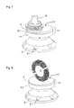
- FIGS. 1 to 12 a perspective view of the block piece and the lens in the various processing processes.
- An in FIG. 1 illustrated block piece 1 has a coupling part 1.1 for receiving and aligning in a workpiece chuck 3 or block chuck according to FIG. 2 and a holding part 1.3 with a receiving surface 1.4 for a lens 2 designed as a spectacle lens FIG. 4 on.
- the holding part 1.3 in this case has such a large diameter that each lens to be produced with a second side 2.2 over the entire surface to bear against the receiving surface 1.4 can be brought.
- the block piece 1 In the center of the receiving surface 1.4, the block piece 1, the mouth of a pressure medium channel 1.6, via the pressure medium from an outer surface 1.7 can be performed in the area of the receiving surface 1.4.
- the workpiece chuck 3 according to FIG. 2 has a plurality of circumferentially spaced recesses 3.1 for retaining screws for the purpose of connecting a flange of a workpiece spindle, not shown.
- the coupling part 1.1 has in addition to a conical or cylindrical holding surface of a certain diameter an end face arranged, acting in the axial direction abutment surface and has two form-fitting storable in the workpiece chuck grooves 3, a cam groove 1.9 for rotational drive of the block piece 1 and an orientation groove 1.8, the Alignment of the block piece 1 relative to the workpiece chuck 3 is used.
- the block piece 1 or the receiving surface 1.4 of the block piece 1 is machined by means of a milling head 7 with a plurality of cutting edges 7.1.
- the receiving surface 1.4 experiences the negative mold corresponding to the second side 2.2 of the spectacle lens 2 to be fastened FIG. 2
- a connection opening 1.6 'of the pressure medium channel 1.6 is shown, which is located on the outside of the block piece 1.
- receiving surface 1.4 now provides the negative mold to a first side 2.1 of the lens 2 according to FIG. 4
- a spray nozzle or adhesive nozzle 8 adhesive or adhesive 5 in the form of a bead is helically applied to the receiving surface 1.4.
- the mouth of the centrally arranged pressure medium channel 1.6 remains free of adhesive.
- the receiving surface 1.4 produced in this way also has a fictitious optical axis 1.5 as a negative surface, as well as the first side 2.1 of the lens 2 to be placed in accordance with FIG FIG. 4 Has.
- the spectacle lens 2 is 2.1 placed with its first side 2.1 against the receiving surface 1.4 of the holding part 1.3 or glued.
- the blank of the spectacle lens 2 shown here is larger in terms of its diameter than the holding part 1.3.
- the blank or the lens 2 form, together with the block piece 1, a so-called block-piece lens pair 1.2, which constantly remains as a unit in the following processing steps.
- the second side 2.2 of the lens 2 is machined by means of the milling head 7 with a plurality of cutting edges 7.1.
- the machining takes place in accordance with the direction of rotation K of the milling head 7 and with respect to a feed direction V from outside to inside.
- the superimposed rotational movements of milling head 7 and lens 2 or workpiece spindle thus results in a better chip formation and there is a better support of the lens 2 before, since the cutting forces act to the side and upwards.
- the chip break thus takes place upwards on the not yet finished surface.
- Such surface defects are processed again in the following processing.
- an edge region R of the lens 2 and of the holding part 1.3 is processed.
- FIG. 6 is mainly the second page 2.2 of the lens 2 after the milling processing now edited for the purpose of fine machining with a turning tool 9 and a cutting plate 9.1 of the turning tool 9.
- the second side 2.2 of the lens 2 is polished over the entire surface via a polishing head 10 with a polishing support 10.1 with full-surface support by the holding part 1.3.
- the lens 2 or the second page 2.2 is cleaned according to Figure 8 by means of a cleaning brush 11, wherein additionally or alternatively, an ultrasonic cleaning is possible.
- the block-piece lens pair 1.2 remained as a unit. Both during polishing and during cleaning, the block piece 1 or the coupling part 1.1 of the block piece 1 is received in a further workpiece chuck 6 with recesses 6.1 for retaining screws.
- the workpiece chuck 6 can also be fastened in other ways.
- FIG. 9 is the first page 2.1 of the lens 2 now completed. It has a second optical axis 2.6 deviating from an optical axis 2.5 of the second side 2.2.
- the features of the lens 2 guaranteeing the optical properties of the spectacle lens are thus divided into the first side 2.1 and the second side 2.2 of the lens 2 in accordance with the optical axes 2.5, 2.6.
- the second side 2.2 of the lens 2 For the purpose of coating the second side 2.2 of the lens 2, it is formed into a bell-shaped block-piece holder 4 together with the block piece, that is to say the respective block-piece lens pairs 1.2, 1.2 ' FIG. 10 introduced or received by this.
- the block pieces 1 are normalized to the extent that they fit in accordance with the preceding machining processes in the various workpiece chucks 3, 6 or Block Communityhalter.
- the first side 2.1 of the lens 2 is created or protected over the entire surface against the receiving surface 1.4 of the holding part 1.3, so that in this coating process only the second side 2.2 of the lens 2 and the edge region R are coated.
- the edge area R or the circumference of the spectacle lens 2 is ground down to the desired level by means of a grinding wheel 12 or a milling cutter, this dimension being independent of a diameter D of the coupling part 1.1 of the block piece 1. Only the edge region R of the spectacle lens 2 and a partial edge region of a holding part 1.3G are machined or ground.
- the grinding wheel 12 also has a circumferential groove 12.1, so that a corresponding edge 2.7 remains on the spectacle lens 2 for the purpose of fastening in a socket during the grinding process.
- the coupling part 1.1 of the block piece 1 is received in a further workpiece chuck 13 with recesses 13.1 for retaining screws.
- the spectacle lens 2 was blocked by the holding part 1.3.
- pressure medium was introduced via the pressure medium channel 1.6 between the receiving surface 1.4 and the first side 2.1 of the lens 2.
- the introduced pressure medium has spread in the free space formed between the receiving surface 1.4 and the first side 2.1 on the one hand and the adjacent beads 5 on the other hand (see flow direction P) and thus initiates the detachment process of the spectacle lens 2.
Landscapes
- Engineering & Computer Science (AREA)
- Mechanical Engineering (AREA)
- Chemical & Material Sciences (AREA)
- Ceramic Engineering (AREA)
- Inorganic Chemistry (AREA)
- Grinding And Polishing Of Tertiary Curved Surfaces And Surfaces With Complex Shapes (AREA)
- Eyeglasses (AREA)
- Lens Barrels (AREA)
- Adornments (AREA)
- Jigs For Machine Tools (AREA)
Description
- Die Erfindung bezieht sich auf ein Blockstück für die Aufnahme einer zu bearbeitenden optischen Linse mit einem eine Rotationsachse aufweisenden Kupplungsteil zur Aufnahme und Ausrichtung in einem Werkstückfutter und einem Halteteil für die Befestigung der Linse, wobei das Halteteil eine konvexe oder konkave Aufnahmefläche entsprechend einer ersten Seite der Linse aufweist. Eine Aufnahmefläche gilt dann als konvex bzw. konkav, wenn sie dem Grunde nach erhaben, also nach außen gewölbt bzw, vertieft oder nach innen gewölbt ist, unabhängig davon, ob sie sphärisch oder asphärisch ausgebildet ist.
- Es ist bereits ein Verfahren zum Schneiden einer Kontaktlinse aus einem zylindrischen Rohling aus der
EP 1 112 143 B1 bekannt. Dabei wird der Rohling zwecks Bearbeitung einer Basisseite auf einem ersten Blockstück aus einem zerspanbaren Kunststoffmaterial befestigt und anschließend wird die bearbeitete Basisseite an einem zweiten Blockstück angebracht, um die Vorderseite herzustellen. Die Innenseite des Rohlings ist dabei konkav ausgebildet, während das Blockstück konvex ausgebildet ist. - Bei der Herstellung von asphärischen Brillengläsern aus Kunststoff ist es allgemein üblich, diese über eine niedrig schmelzende Legierung mit dem Blockstück zu verbinden. Hierzu wird ein durch das Blockstück und die Linse begrenzter Raum mit der Legierung gefüllt, so dass die Legierung die Form der asphärischen Fläche der Linse annimmt und die Linse mit dem Blockstück verbindet. Der Einsatz der Legierung ist kostenintensiv und bezüglich des zeitlichen Verfahrensablaufs nachteilig, da relativ viel Legierung benötigt wird. Die Legierung muss warm eingeformt, abgekühlt und zwecks Abblocken wieder aufgeschmolzen werden. Während des Abkühlvorgangs muss die relative Position zwischen dem Blockstück und der Linse fixiert werden. Die zu verbindende Seite der Linse ist dabei sphärisch, damit die Dichtigkeit bei der Anlage an das Blockstück zwecks Befüllung mit flüssigem Alloy gewährleistet ist. Bei asphärischen Flächen ist eine Dichtungslippe zwischen dem Blockstück und der Linse vorgesehen, die eine dichtende Anlage gewährleistet.
- Alternativ beschreibt die
JP 11198014 A - Dokument
US4925518 beschreibt ein Blockstück gemäß dem Oberbegriff der Ansprüche 1 und 2. - Der Erfindung liegt die Aufgabe zugrunde, ein Blockstück und ein Verfahren zum Auf- und Abblocken derart auszubilden, dass ein optimales Auf- und Abblocken der Linse gewährleistet sind.
- Gelöst wird die Aufgabe erfindungsgemäß durch die Merkmale der Ansprüche 1 und 2. Hierdurch wird erreicht, dass die erste Seite der Linse nahezu unbeabstandet gegen die Aufnahmefläche zur Anlage bringbar ist und somit die Menge des zu verwendenden Haftmittels auf ein Minimum reduziert wird. Die Art des Anlageverhältnisses zwischen der Aufnahmefläche und der ersten Seite bzw. Linsenfläche hängt von der Rauhigkeit der Flächen, von der Viskosität des verwendeten Haftmittels und von der verwendeten Anlage- bzw. Anpresskraft ab. Idealerweise befindet : sich zwischen beiden Flächen so wenig Haftmittel wie möglich. Das Haftmittel stellt dabei kein Distanzmittel dar, sondern dient lediglich der Füllung bzw. Abdichtung der vorhandenen Spalte bzw. Rauhigkeiten zwischen beiden Flächen. Da in Verbindung mit der Aktivierung von Haftmittel bzw. mit der Einbringung von Haftmittel in der Regel ein Wärmeeintrag notwendig ist, ist im erfindungsgemäßen Fall ein entsprechend reduzierter Wärmeeintrag für die Aktivierung bzw. Einbringung der so gebildeten äußerst dünnen Klebeschicht notwendig.
- Ferner kann neben der asphärisch ausgebildeten ersten Seite der Linse nunmehr die zu bearbeitende zweite Seite der Linse ebenfalls asphärisch, also torisch oder progressiv ausgebildet werden, so dass die die optischen Eigenschaften der Linse begründenden Formen bzw. Merkmale, also Radien, optische Achsen, optische Teilflächen oder Prismen der Linse optimal auf beide Seiten der Linse verteilt werden können.
- Darüber hinaus kann die Linse ganzflächig gegen die Aufnahmefläche anliegen und so ganzflächig durch diese gestützt werden, wobei aufgrund der Zerspanbarkeit des Blockstücks jegliche Formgestaltung der Linse mit Rücksicht auf den Durchmesser bzw. die Breite derselben möglich ist.
- Zwecks Aufnahme spezieller sphärischer Linsen weist das Halteteil eine konvexe oder konkave sphärische Aufnahmefläche mit einer Hauptachse auf, die die Ausrichtung der so gebildeten Kugelteilfläche beschreibt.
- Erfindungsgemäß ist entsprechend der Ausrichtung der aufzunehmenden Linse die Aufnahmefläche als Negativfläche zur Linse ausgebildet, wobei die Hauptachse der Negativfläche bzw. Aufnahmefläche versetzt und/oder gekippt zur Rotationsachse des Kupplungsteils angeordnet ist. Die sphärische Fläche des Blockstücks ist somit individuell der Ausrichtung der aufzunehmenden Linse nach gestaltet, so dass der sich anschließende Bearbeitungsprozess optimal ausgeführt werden kann.
- Vorteilhaft ist es, dass die Aufnahmefläche neben den oben genannten Flächenformen auch sphärisch ausgebildet sein kann und unabhängig von der Flächenform oder deren Ausrichtung mehrere, insbesondere drei punktförmige Abstützstellen für die aufzunehmende Linse aufweist, wobei der übrige Teil der Aufnahmefläche relativ zu den Abstützstellen etwas zurücksteht. Somit ist eine definierte Anlage der Linse gegen die Aufnahmefläche gewährleistet. In dieser Ausgestaltungsvariante ist zwar etwas mehr Haftmittel erforderlich, als wenn die Linse nahezu ganzflächig anliegt. Jedoch können auch für Linsen, deren aufzunehmende erste Seite nicht bekannt ist, zumindest die Abstützstellen ermittelt werden, wohingegen der übrige Teil der Linsenfläche grob bzw. nur teilweise mit geringer Genauigkeit ermittelt werden muss.
- Dabei ist es von Vorteil, dass der übrige zurückstehende Teil der Aufnahmefläche näherungsweise die Form der ersten Seite der aufzunehmenden Linse aufweist. Mit Bezug auf die vorgehend genannte Ermittlung der Linsenfläche kann das damit einhergehende Ermittlungs- bzw. Vermessungsverfahren der ersten Seite auf ein notwendiges Maß beschränkt werden, so dass auch Messmittel mit geringer Auflösung, wie Messfühler bzw. Messigel, verwendet werden können. Der Messigel dient dabei zur gleichzeitigen Erfassung mehrerer Messpunkte auf der Fläche. Zum anderen kann der spanende Bearbeitungsschritt auf ein ausreichendes Maß an Komplexität reduziert werden, so dass im ganzen eine schnellere Herstellung der Anlagefläche gewährleistet ist.
- Hierzu ist es von Vorteil, dass die punktförmigen Abstützstellen der Aufnahmefläche einen Teil einer fiktiven Fläche bilden, wobei die fiktive Fläche die Form der ersten Seite der aufzunehmenden Linse beschreibt. Somit sind neben der definierten Anlage bzw. Auflage der Linse die Abstützstellen selbst definiert. Die Linse kann exakt der Anlagefläche nach ausgerichtet und aufgelegt bzw. fixiert werden. Der zwischen der Anlagefläche und der Linse bestehende Freiraum ist dabei auf ein abschätzbares, relativ kleines Maß begrenzt, so dass erfindungsgemäß sehr wenig Haftmittel notwendig ist. Die Anlagefläche steht relativ zu den Abstützstellen um etwa 0,01 mm bis 0,5 mm zurück. Insbesondere bei Linsen mit unbekannter Flächenform der ersten aufzunehmenden Seite, die mit vorstehend genannten Messmitteln vermessen werden müssen, ist vorgenannter Rückstand bzw. Abstand in der Regel größer als bei Linsen, deren Geometrie der aufzunehmenden Fläche bekannt ist. In Ausnahmefällen kann vorgenannter Abstand auch größer als 0,5 mm sein. Zwecks Aufnahme von unbekannten Linsen muss die zurückgesetzte Aufnahmefläche vereinfacht werden, da die aufzunehmende Fläche nur mit einer begrenzten Auflösung ermittelbar ist. Dies ist bei Linsen mit bekannter Flächenform nicht der Fall. Hier dient die Annährung der Aufnahmefläche lediglich einer beschleunigten Herstellung derselben, da der damit einhergehende Rechenaufwand der Bearbeitungsmaschine verringert wird. Die Abstützstellen sind dabei aber Teil der fiktiven Fläche, die exakt der Flächenform der aufzunehmenden ersten Seite entspricht.
- Die meisten Linsen weisen trotz asphärischer Gesamtform zumindest sphärische Teilbereiche auf. Die Abstützstellen befinden sich dabei vorzugsweise in solchen sphärischen Teilbereichen, die dann auf der Aufnahmefläche als Teil der fiktiven Gesamtfläche exakt abgebildet werden.
- Eine zusätzliche Möglichkeit ist gemäß einer Weiterbildung, dass mindestens ein Druckmittelkanal zwischen der Aufnahmefläche und einer Außenfläche vorgesehen ist, über den Druckmittel von außen in den Bereich zwischen der Aufnahmefläche und der aufnehmbaren Linse bringbar ist. Zum Abblocken bzw. Lösen der Linse vom Blockstück ist das Einbringen von Druckmitteln wie Luft, Wasser oder Flüssigkeiten mit anderen Viskositäten zwischen die Aufnahmefläche und die jeweilige Linse vorteilhaft, da dieser Abblockvorgang sehr zügig und ohne die Einbringung zusätzlicher Wärme erfolgen kann. Der Druckmittelkanal entspringt dabei an einer Außenfläche des Blockstücks, so dass ein entsprechender Druckmittelanschluss bzw. eine entsprechende Druckmittelleitung anschließbar ist.
- Vorteilhaft ist es hierzu auch, dass in der Aufnahmefläche mindestens ein Ausgleichskanal zur Aufnahme von überschüssigem Haftmittel vorgesehen ist. Der Ausgleichskanal kann dabei als Nut, Bohrung oder Ausnehmung ausgebildet sein, so dass beim Anlegen einer Linse der überschüssige, zwischen der Linse und der Aufnahmefläche befindliche Kleber in den bzw. die zur Verfügung stehenden Ausgleichskanäle gepresst wird. Damit kann der zwischen der Linse und der Aufnahmefläche befindliche Teil des Haftmittels auf vorgenanntes Minimum reduziert werden.
- Ferner ist es vorteilhaft, dass der Ausgleichskanal und/oder der Druckmittelkanal stern-, spiral- und/oder kreisförmig ausgebildet ist. Dabei sind Anzahl und Größe der jeweiligen Kanäle derart zu wählen, dass die Linse auch ganzflächig und ausreichend durch das Blockstück gestützt wird, so dass das Blockstück die erforderliche Steifigkeit nicht verliert. Der Ausgleichskanal kann dabei kreisförmig am Außenrand der Aufnahmefläche vorgesehen sein, damit das seitlich beim Aufblocken austretende überschüssige Haftmittel aufgefangen wird und nicht auf das Werkstückfutter läuft.
- Vorteilhaft ist es auch, dass der Druckmittelkanal mit Bezug zur Fließrichtung des Druckmittels einen sich aufweitenden Querschnitt aufweist. Beim Aufsetzen der Linse auf das Blockstück wird sich das aufgebrachte Haftmittel zwangsläufig in die bestehenden Druckmittelkanäle eindrücken, so dass dieses beim Lösen der Linse wieder herausgedrückt werden muss. Durch die vorgenannte Querschnittsausbildung ist das Ausdrücken des zumindest teilweise erhärteten Haftmittels ohne weiteres möglich, da keine Hinterschneidung besteht.
- Dabei ist es vorteilhafterweise vorgesehen, dass mehrere Druckmittelkanäle gleichmäßig verteilt an der Aufnahmefläche münden und dass der Druckmittelkanal einen trichterförmigen Mündungsbereich aufweist. Die verschiedenen Druckmittelkanäle können dabei anstatt vorgenannter Ausgleichskanäle vorgesehen sein, da diese zwangsläufig überschüssiges Haftmittel aufnehmen. Die Verteilung der Druckmittelkanäle gewährleistet eine optimale Lösung bzw. ein optimales Abblocken der Linse, so dass diese beim Ablöseprozess nicht beschädigt wird.
- Im Zusammenhang mit der erfindungsgemäßen Ausbildung und Anordnung ist es von Vorteil, dass der Druckmittelkanal zentrisch, im Bereich einer Mittelachse der Aufnahmefläche und/oder im Bereich der punktförmigen Abstützstellen mündet. Das Blockstück dient zur Herstellung verschiedenster Linsenformen, wobei auch sehr kleine Linsen zu berücksichtigen sind. Mit der Anordnung des Druckmittelkanals nahe des Zentrums der Aufnahmefläche steht dieser unabhängig von der herzustellenden Größe der Linse und der damit einhergehenden spanenden Bearbeitung der Linse einerseits sowie des Blockstücks andererseits auf jeden Fall zur Verfügung. Bei einer Anordnung des Druckmittelkanals bzw. seiner Mündung im Bereich der Abstützstellen ist das Abblocken relativ einfach zu gestalten, da das Trennen der Linse von der jeweiligen relativ kleinen Abstützstelle ohne zusätzlichen Aufwand erfolgt.
- Vorteilhaft ist es ferner, dass das Blockstück als Kunststoff-Spritzgussteil ausgebildet ist. Somit ist eine günstige und sehr schnelle Herstellung des Blockstücks gewährleistet.
- Außerdem ist es vorteilhaft, dass die Aufnahmefläche oder zumindest die punktförmigen Abstützstellen der Aufnahmefläche zwecks Generierung einer Klebekraft aktivierbar sind und klebende Eigenschaften aufweisen. Das Blockstück bzw. zumindest das Halteteil kann bei der Herstellung unabhängig von einer etwaigen Ein- oder Mehrteiligkeit des Blockstücks aus zwei Kunststoffsorten gebildet sein, die den jeweiligen Anforderungen, also denen eines Kupplungsteils einerseits und denen eines Halteteils mit Aufnahmefläche bzw. einer Abstützstelle andererseits, gerecht werden. Das Halteteil könnte dabei zumindest im Bereich der Aufnahmefläche bzw. der Abstützstellen aus einem Kunststoff gefertigt sein, der nach einer Aktivierung durch Anwärmen oder Anschmelzen bzw. Anlösen klebende Eigenschaften entwickelt, so dass die Linse ohne Auftrag zusätzlichen Haftmittels oder ohne die Verwendung einer Klebefolie auf die Aufnahmefläche aufgeklebt bzw. mit dieser verbunden werden kann. Im Falle des Anwärmens ist auch ein sehr geringer Wärmeeintrag nötig und somit eine schnelle Abkühlung gewährleistet.
- Dabei ist es von Vorteil, dass das Blockstück mindestens zweiteilig ausgebildet ist. Somit muss nach Fertigstellung der Linse lediglich das zerspante Halteteil entsorgt werden, wobei das Kupplungsteil weiter verwendet wird.
- Ferner ist es vorteilhaft, dass zwecks Befestigung der Linse eine zweiseitig wirksame Klebefolie auf der Aufnahmefläche bzw. zumindest im Bereich ihrer punktförmigen Abstützstellen anbringbar ist. Da die Linse auf der zu haltenden Seite ohnehin durch Anbringung einer Folie gegen Beschädigungen geschützt werden muss, stellt der Einsatz einer zweiseitig wirksamen Klebefolie, die einerseits auf die erste Seite der Linse aufgeklebt wird und andererseits zum Befestigen derselben auf der Aufnahmefläche dient, einen optimalen Lösungsweg dar.
- Gelöst wird die Aufgabe auch durch das Verfahren zum Aufblocken einer optischen Linse gemäß Anspruch 16. Dabei wird vor dem Aufblocken die Aufnahmefläche spanend bearbeitet und damit eine der ersten Seite der Linse entsprechende Negativform generiert, die die gleichen Radien, Teilflächen und optischen Achsen oder eine Annährung an diese aufweist. Auf die Aufnahmefläche und/oder die Linse wird ein Haftmittel aufgebracht und/oder die Aufnahmefläche wird zwecks Entwicklung einer Klebekraft aktiviert. Die Aufnahmefläche des Blockstücks und die erste Seite der Linse werden bezüglich ihrer jeweiligen Lage bzw. Ausrichtung der optischen Achsen zueinander ausgerichtet, die erste Seite und die Aufnahmefläche werden verbunden bzw. zumindest teilweise gegeneinander zur An- bzw. Auflage gebracht und somit ein Blockstück-Linsenpaar gebildet. Vorzugsweise ist der mittlere Abstand zwischen der Aufnahmefläche und der Linse zwischen 0,01 mm und 0,5 mm. Theoretisch stützt sich die Linse in diesem Fall in zumindest drei Punkten statisch bestimmt auf der Aufnahmefläche ab, wobei bei einem Haftmittel mit hoher Viskosität und bei geringen Auflagekräften eine direkte Anlage der Linse nicht gegeben sein muss. Hierdurch wird erreicht, dass die erste Seite der Linse nahezu unbeabstandet gegen die Aufnahmefläche zur Anlage bringbar ist und somit die Menge des zu verwendenden Haftmittels auf ein Minimum reduziert wird. Da in Verbindung mit der Aktivierung von Kleber bzw. mit der Einbringung von Kleber in der Regel ein Wärmeeintrag notwendig ist, ist im erfindungsgemäßen Fall ein entsprechend reduzierter Wärmeeintrag für die Aktivierung bzw. Einbringung der so gebildeten äußerst dünnen Klebeschicht notwendig.
- Dabei ist es von Vorteil, dass die Aufnahmefläche derart bearbeitet wird, dass mehrere, insbesondere drei punktförmige Abstützstellen für die aufzunehmende Linse und ein relativ zu den Abstützstellen etwas zurückstehender Teil der Aufnahmefläche generiert werden, wobei die punktförmigen Abstützstellen der Aufnahmefläche einen Teil einer fiktiven Fläche bilden, die die Form der ersten Seite der aufzunehmenden Linse beschreibt und der zurückstehende Teil nur näherungsweise die Form der aufzunehmenden Linse beschreibt.
- Schließlich ist es von Vorteil, dass die Verfahrensschritte Formen und Haftmittelauftrag und/oder die Verfahrensschritte Haftmittelauftrag und Ausrichten in umgekehrter Reihenfolge ausgeführt oder abgearbeitet werden. Soweit das Haftmittel auf die Linse aufgebracht wird, kann der Verfahrensschritt Haftmittelauftrag auch vor dem Verfahrensschritt Formen erfolgen, so dass nach dem Aufbringen des Haftmittels auf die Linse erst die spanende Bearbeitung des Blockstücks erfolgt. Darüber hinaus ist es auch möglich, das Haftmittel erst nach dem Ausrichten von Blockstück und Linse aufzubringen, insbesondere dann, wenn zwischen dem Aufbringen des Haftmittels und dem Zeitpunkt des Anlegens der Linse an die Aufnahmefläche wegen der Aushärtezeit des Haftmittels so wenig Zeit wie möglich vergehen sollte.
- Vorteilhaft ist es hierzu auch, dass das Haftmittel spiral-, stern- und/oder punktförmig auf den Abstützstellen aufgebracht wird. Beim spiralförmigen Aufbringen des Haftmittels sollte der zentrisch vorgesehene Druckmittelkanal bzw. die weiteren Druckmittelkanäle freigehalten werden, so dass sich zum Abblocken das Druckmittel in den durch die Linse und die Aufnahmefläche einerseits sowie benachbarte Haftmittelraupen andererseits gebildeten Freiraum ausbreiten kann. Der sich fortpflanzende, durch das strömende Druckmittel aufgebaute dynamische Druck sorgt somit für eine umfangreiche Lösekraft, die das Abblocken der Linse bzw. das Lösen der Linse später gewährleistet.
- Letztlich ist es von Vorteil, dass das Haftmittel unter Einsatz von Wärmestrahlung und/oder UV-Strahlung ausgehärtet wird. Je nach Einsatz von Haftmittel ist diese Aushärtung durch UV-Strahlung oder sonstigen Energieeintrag wie Erwärmen oder dergleichen möglich.
- Ferner ist es vorteilhaft, dass das Haftmittel als doppelseitig wirkende Klebefolie ausgebildet ist und gegen die Aufnahmefläche und die Linse zur Anlage gebracht wird. Da die Linse auf der zu haltenden Seite ohnehin durch Anbringung einer Folie gegen Beschädigungen geschützt werden muss, stellt der Einsatz einer zweiseitig wirksamen Klebefolie, die einerseits auf die erste Seite der Linse aufgeklebt wird und andererseits zum Befestigen derselben auf der Aufnahmefläche dient, einen optimalen Lösungsweg dar.
- Vorteilhaft ist es außerdem, dass vor oder nach dem Bearbeiten der Aufnahmefläche mindestens ein Ausgleichskanal für überschüssiges Haftmittel in die Aufnahmefläche eingearbeitet wird und/oder dass vor oder nach dem Bearbeiten der Aufnahmefläche mindestens eine als Druckmittelkanal ausgebildete, die Kommunikation zwischen der Aufnahmefläche und der Umgebung gewährleistende Ausnehmung in das Blockstück eingearbeitet wird. Je nach gewünschter Linsenform kann ein individuelles Ausbilden der Ausgleichs- bzw. Druckmittelkanäle erforderlich und erfindungsgemäß vorteilhaft sein. Dabei ist auch die Verbindung verschiedener Kanäle, die an verschiedenen Punkten der Aufnahmefläche münden, möglich.
- Schließlich ist es von Vorteil, dass die Aushärtung des Haftmittels der Dauer und/oder der Intensität nach derart erfolgt, dass das Haftmittel im Wesentlichen nur im Bereich zwischen der Linse und der Aufnahmefläche vollständig aushärtet und im Bereich des Ausgleichskanals und/oder des Druckmittelkanals nicht aushärtet. Somit wird beim Abblocken bzw. Lösen der Linse das einströmende Druckmittel nicht am Eintritt zwischen Linse und Aufnahmefläche gehindert, so dass mit Rücksicht auf die vermiedenen Klebekräfte innerhalb der Kanäle ein einfacheres und kontrollierteres Ablösen der Linse gewährleistet ist.
- Vorteilhaft ist es hierzu auch, dass nach dem Verbinden der Linse mit dem Blockstück das spanende Bearbeiten und/oder das Polieren der zweiten Seite der Linse erfolgt. Die erfindungsgemäße aufgeblockte Linse kann nun in jeglicher Weise bearbeitet werden, wobei das jeweilige Blockstück-Linsenpaar nach der Herstellung für alle weiteren Verfahrensschritte bis zur Fertigstellung der Linse als Einheit verbleibt.
- Ferner ist es vorteilhaft, dass zum Polieren der Linse das Blockstück-Linsenpaar in ein weiteres Werkstückfutter eingespannt wird. Das erfindungsgemäße Blockstück bzw. das erfindungsgemäß gebildete Blockstück-Linsenpaar kann dabei in alle zur Bearbeitung notwendigen Aufnahmen der Folgestationen, also Werkstückfutter bzw. Blockstückhalter, eingesetzt werden.
- Vorteilhaft ist es außerdem, dass nach dem Bearbeiten und/oder Polieren der Linse das Beschichten der aufgeblockten Linse erfolgt und dass zum Beschichten der Linse mindestens ein Blockstück-Linsenpaar in einem weiteren Blockstückhalter aufgenommen wird. In der Regel werden mehrere Linsen gleichzeitig beschichtet, wobei diese bzw. die Blockstück-Linsenpaare nebeneinander im Bereich einer Verdampfungs- bzw. Beschichtungsquelle angeordnet werden. Dabei ist es sehr wichtig, dass nur die zu bearbeitende erste Seite bzw. der Randbereich der Linse beschichtet werden. Da die nicht zu bearbeitende zweite Seite erfindungsgemäß ganzflächig durch das Blockstück abgedeckt ist, bleibt diese unweigerlich frei von ungewünschtem Beschichtungsmittel. Das erfindungsgemäße Blockstück verbleibt als Teil des Blockstück-Linsenpaares bei der Linse und kann durch den Blockstückhalter zwecks Beschichtung aufgenommen werden. Schließlich ist es von Vorteil, dass nach dem Beschichten der Linse der Randbereich R des Blockstück-Linsenpaares spanend bearbeitet oder geschliffen wird. Nach dem Beschichten der Linse ist es wünschenswert, dass der Randbereich der nunmehr beschichteten Linse, auf dem aufgrund von Konturläufen und Oberflächenspannungen Beschichtungsfehler auftreten können, abgearbeitet wird. Erfindungsgemäß ist dieser Bearbeitungsschritt der Anpassung der Linsengröße sowie der Bearbeitung des Randbereichs zwecks Aufnahme in einer Brillenfassung nach dem Beschichten vorgesehen. Durch das spanbare bzw. schleifbare Blockstück, welches erfindungsgemäß an der Linse verbleibt, kann diese ohne weiteren Umblockaufwand unabhängig von ihrer Größe und der Form des Randbereichs fertiggestellt werden. Das erfindungsgemäße Blockstück gewährleistet auch eine freie Bearbeitung der Linse ohne Behinderung durch sonst übliche weitere Spann- bzw. Klemmmittel. Auch Bohrungen etc. können ohne weiteres vorgenommen werden.
- Ferner ist es vorteilhaft, dass zum Abblocken der Linse Druckmittel über den Druckmittelkanal zwischen die erste Seite der Linse und die Aufnahmefläche des Blockstücks bzw. zumindest die punktförmigen Abstützstellen der Aufnahmefläche eingebracht wird. Je nach Ausbildung des Klebers mit Rücksicht auf die Form beim Auftragen des Klebers bzw. Haftmittels setzt sich das Druckmittel in dem vorstehend beschriebenen, nicht gedichteten Freiraum bzw. Spalt zwischen Linse, Aufnahmefläche und Haftmittelraupen fort, so dass das Ablösen der Linse nach und nach bewirkt wird. Aber auch bei ganzflächig aufgetragenem Haftmittel, wenn also keine Undichtigkeiten zwischen der Aufnahmefläche und der Linse vorhanden sind, wie bei der Klebefolie oder anderen Klebevarianten wie das Anschmelzen der Aufnahmefläche ist die stetige Fortsetzung des Druckmittels ausgehend von der Mündung des Druckmittelkanals bzw. der verschiedenen Mündungen gewährleistet.
- Vorteilhaft ist es außerdem, dass zum Abblocken und/oder Lösen der Linse das Haftmittel und/oder die Linse erwärmt oder abgekühlt werden. Dadurch, dass erfindungsgemäß sehr wenig Haftmittel bzw. Kleber verwendet werden kann, ist der Ablösevorgang durch Erwärmung bzw. Abkühlung des Haftmittels sehr schnell möglich, da nur wenig Haftmittel vorhanden ist. Beim Abkühlen wird das Haftmittel spröde.
- Erfindungsgemäß ist es vorteilhaft, dass zum Abblocken und/oder Lösen der Linse das verbleibende Halteteil und/oder das Kupplungsteil des Blockstücks derart verformt wird, dass sich die Aufnahmefläche verformt und sich von der Linse zumindest teilweise löst. Das verbleibende Halteteil und/oder das Kupplungsteil wird hierzu in einer in radialer Richtung wirkenden Spannzange aufgenommen, die eine entsprechende Klemmkraft generiert, so dass das verbleibende Halteteil und/oder das Kupplungsteil gestaucht wird. Als Folge dieser Stauchung wölbt sich das verbleibende Halteteil aus und die Linse löst sich von der Aufnahmefläche bzw. vom Kleber. Dass die Klebeschicht erfindungsgemäß sehr dünn ist, begünstigt auch das Abblockverfahren.
- Als Alternative ist es von Vorteil, dass vor dem Verformen das Halteteil und/oder das Kupplungsteil des Blockstücks mit mindestens einem Schlitz versehen bzw. geschlitzt und erst anschließend verformt werden. Dazu muss das Blockstück-Linsenpaar aus dem Werkstückfutter entnommen und ggf. linsenseitig gehalten werden, so dass das Kupplungsteil mittels einer Säge oder eines Fräsers geschlitzt werden kann.
- Hierbei ist es von vorteil, dass das Halteteil und/oder das Kupplungsteil zwecks Verformung in eine Richtung quer zum Schlitz mit einer Klemmkraft beaufschlagt werden. Der Schlitz ist dabei so tief, dass sich beim anschließenden Verformungsprozess durch Klemmen bzw. Zusammendrücken zumindest des Kupplungsteils der Schlitz zumindest teilweise schließt und sich dabei auch das Halteteil verformt, so dass sich dieses zumindest von einem Teil der Linse löst. Der Schlitz reicht dabei vorzugsweise bis unmittelbar vor das Glas, also auch bis in das Halteteil, so dass eine Restwandstärke des Blockstücks von etwa 1 mm bis 2 mm verbleibt. Beim Klemmen wird der Löseprozess am Rand initiiert und setzt sich dann aufgrund der anhaltenden Verformung zur Mitte hin fort.
- Weitere Vorteile und Einzelheiten der Erfindung sind in den Patentansprüchen und in der Beschreibung erläutert und in den Figuren dargestellt.
- Dabei zeigen die
Figuren 1 bis 12 eine perspektivische Darstellung des Blockstücks und der Linse bei den verschiedenen Bearbeitungsprozessen. - Ein in
Figur 1 dargestelltes Blockstück 1 weist ein Kupplungsteil 1.1 zur Aufnahme und Ausrichtung in einem Werkstückfutter 3 bzw. Blockstückfutter gemäßFigur 2 sowie ein Halteteil 1.3 mit einer Aufnahmefläche 1.4 für eine als Brillenglas ausgebildete Linse 2 gemäßFigur 4 auf. Das Halteteil 1.3 weist dabei einen derart großen Durchmesser auf, dass jedes herzustellende Brillenglas mit einer zweiten Seite 2.2 ganzflächig zur Anlage gegen die Aufnahmefläche 1.4 bringbar ist. Im Zentrum der Aufnahmefläche 1.4 weist das Blockstück 1 die Mündung eines Druckmittelkanals 1.6 auf, über den Druckmittel von einer Außenfläche 1.7 in den Bereich der Aufnahmefläche 1.4 geführt werden kann. Das Werkstückfutter 3 gemäßFigur 2 weist mehrere über den Umfang verteilt angeordnete Ausnehmungen 3.1 für Halteschrauben zwecks Anbindung eines nicht dargestellten Flansches einer Werkstückspindel auf. - Das Kupplungsteil 1.1 weist neben einer konischen bzw. zylindrischen Haltefläche eines bestimmten Durchmessers eine stirnseitig angeordnete, in axiale Richtung wirkende Anlagefläche auf und besitzt zwei formschlüssig im Werkstückfutter 3 lagerbare Nuten, eine Mitnehmernut 1.9 zum rotatorischen Antrieb des Blockstücks 1 und eine Orientierungsnut 1.8, die zur Ausrichtung des Blockstücks 1 relativ zum Werkstückfutter 3 dient.
- Gemäß
Figur 2 wird das Blockstück 1 bzw. die Aufnahmefläche 1.4 des Blockstücks 1 mittels eines Fräskopfes 7 mit mehreren Schneiden 7.1 spanend bearbeitet. Die Aufnahmefläche 1.4 erfährt dabei die Negativform entsprechend der zweiten Seite 2.2 des zu befestigenden Brillenglases 2. InFigur 2 ist zudem eine Anschlussöffnung 1.6' des Druckmittelkanals 1.6 dargestellt, die sich an der Außenseite des Blockstücks 1 befindet. - Die in
Figur 3 dargestellte Aufnahmefläche 1.4 stellt nun die Negativform zu einer ersten Seite 2.1 des Brillenglases 2 gemäßFigur 4 dar. Über eine Spritzdüse bzw. Haftmitteldüse 8 wird Haftmittel bzw. Kleber 5 in Form einer Raupe schneckenförmig auf die Aufnahmefläche 1.4 aufgetragen. Die Mündung des zentrisch angeordneten Druckmittelkanals 1.6 bleibt dabei frei von Haftmittel. Die so hergestellte Aufnahmefläche 1.4 weist als Negativfläche ebenso eine fiktive optische Achse 1.5 auf, wie sie auch die aufzulegende erste Seite 2.1 der Linse 2 gemäßFigur 4 hat. - Gemäß
Figur 4 ist das Brillenglas 2 mit seiner ersten Seite 2.1 gegen die Aufnahmefläche 1.4 des Halteteils 1.3 aufgelegt bzw. aufgeklebt. Der hier dargestellte Rohling des Brillenglases 2 ist dabei betreffend seinen Durchmesser größer als das Halteteil 1.3. Das ist jedoch nicht nachteilig, da das herzustellende Brillenglas 2 deutlich kleiner wird als der Rohling, so dass dieses letztlich wie vorstehend beschrieben ganzflächig auf dem Halteteil 1.3 aufliegt. Der Rohling bzw. die Linse 2 bilden zusammen mit dem Blockstück 1 ein sogenanntes Blockstück-Linsenpaar 1.2, welches in den folgenden Bearbeitungsschritten ständig als Einheit verbleibt. - Gemäß
Figur 5 wird die zweite Seite 2.2 der Linse 2 mittels des Fräskopfes 7 mit mehreren Schneiden 7.1 spanend bearbeitet. Die Bearbeitung erfolgt dabei gemäß Drehrichtung K des Fräskopfes 7 sowie bezüglich einer Vorschubrichtung V von außen nach innen. Mit Rücksicht auf die überlagerten Drehbewegungen von Fräskopf 7 und Linse 2 bzw. Werkstückspindel ergibt sich somit eine bessere Spanbildung und es herrscht eine bessere Abstützung der Linse 2 vor, da die Schneidkräfte zur Seite und nach oben wirken. Der Spanabriss erfolgt somit nach oben auf der noch nicht fertig bearbeiteten Fläche. Solche Oberflächenfehler werden in der folgenden Bearbeitung wieder abgearbeitet. Bei der fräsenden Bearbeitung gemäßFigur 5 wird neben der zweiten Seite 2.2 der Linse 2 auch ein Randbereich R der Linse 2 sowie des Halteteils 1.3 bearbeitet. - Gemäß
Figur 6 wird vornehmlich die zweite Seite 2.2 der Linse 2 nach der fräsenden Bearbeitung nunmehr zwecks Feinbearbeitung mit einem Drehmeißel 9 bzw. einer Schneidplatte 9.1 des Drehmeißels 9 bearbeitet. - Gemäß
Figur 7 wird die zweite Seite 2.2 der Linse 2 über einen Polierkopf 10 mit einer Polierauflage 10.1 mit vollflächiger Unterstützung durch das Halteteil 1.3 ganzflächig poliert. - Danach wird die Linse 2 bzw. die zweite Seite 2.2 gemäß Figur 8 mittels einer Reinigungsbürste 11 gereinigt, wobei ergänzend oder alternativ auch eine Ultraschallreinigung möglich ist. In allen bisherigen Verfahrensschritten ist das Blockstück-Linsenpaar 1.2 als Einheit verblieben. Sowohl beim Polieren als auch beim Reinigen ist das Blockstück 1 bzw. das Kupplungsteil 1.1 des Blockstücks 1 in einem weiteren Werkstückfutter 6 mit Ausnehmungen 6.1 für Halteschrauben aufgenommen. Das Werkstückfutter 6 kann auch auf andere Weise befestigt werden.
- Gemäß
Figur 9 ist die erste Seite 2.1 der Linse 2 nunmehr fertiggestellt. Sie weist eine von einer optischen Achse 2.5 der zweiten Seite 2.2 abweichende zweite optische Achse 2.6 auf. Die die optischen Eigenschaften des Brillenglases gewährleistenden Merkmale der Linse 2 sind somit entsprechend den optischen Achsen 2.5, 2.6 auf die erste Seite 2.1 und die zweite Seite 2.2 der Linse 2 aufgeteilt. - Zwecks Beschichtung der zweiten Seite 2.2 der Linse 2 wird diese zusammen mit dem Blockstück, also den jeweiligen Blockstück-Linsenpaaren 1.2, 1.2', in einen glockenförmigen Blockstückhalter 4 gemäß
Figur 10 eingebracht bzw. durch diesen aufgenommen. Die Blockstücke 1 sind soweit normiert, dass sie gemäß den vorangehenden Bearbeitungsprozessen in die verschiedenen Werkstückfutter 3, 6 bzw. Blockstückhalter passen. Die erste Seite 2.1 der Linse 2 ist dabei ganzflächig gegen die Aufnahmefläche 1.4 des Halteteils 1.3 angelegt bzw. geschützt, so dass bei diesem Beschichtungsvorgang lediglich die zweite Seite 2.2 der Linse 2 bzw. der Randbereich R beschichtet werden. - Da bei der Beschichtung insbesondere im Randbereich der Linse 2 Fehler auftreten können, erfolgt zwecks Herstellung der endgültigen Form die Bearbeitung des Randbereichs R erst nach dem Beschichten.
- Gemäß
Figur 11 wird mittels einer Schleifscheibe 12 bzw. eines Fräsers der Randbereich R bzw. der Umfang des Brillenglases 2 auf das gewünschte Maß heruntergeschliffen, wobei dieses Maß unabhängig von einem Durchmesser D des Kupplungsteils 1.1 des Blockstücks 1 ist. Es werden lediglich der Randbereich R des Brillenglases 2 sowie ein Teilrandbereich eines Halteteils 1.3G bearbeitet bzw. geschliffen. Die Schleifscheibe 12 weist zudem eine Umfangsnut 12.1 auf, so dass beim Schleifvorgang ein entsprechender Rand 2.7 am Brillenglas 2 zwecks Befestigung in einer Fassung verbleibt. Das Kupplungsteil 1.1 des Blockstücks 1 ist in einem weiteren Werkstückfutter 13 mit Ausnehmungen 13.1 für Halteschrauben aufgenommen. - Gemäß
Figur 12 wurde das Brillenglas 2 vom Halteteil 1.3 abgeblockt. Hierzu wurde nicht dargestelltes Druckmittel über den Druckmittelkanal 1.6 zwischen die Aufnahmefläche 1.4 und die erste Seite 2.1 der Linse 2 eingebracht. Mit Rücksicht auf die auf der Aufnahmefläche 1.4 befindliche Haftmittelraupe 5 hat sich das eingebrachte Druckmittel in den zwischen Aufnahmefläche 1.4 und erster Seite 2.1 einerseits sowie die benachbarten Raupen 5 andererseits gebildeten Freiraum (siehe Strömungsrichtung P) ausgebreitet und so den Ablöseprozess des Brillenglases 2 initiiert. -
- 1
- Blockstück
- 1.1
- Kupplungsteil
- 1.2
- Blockstück-Linsenpaar
- 1.2'
- Blockstück-Linsenpaar
- 1.3
- Halteteil
- 1.3G
- Halteteil, geschliffen
- 1.4
- Aufnahmefläche
- 1.5
- optische Achse, fiktiv
- 1.6
- Druckmittelkanal, Ausnehmung
- 1.6'
- Anschlussöffnung
- 1.7
- Außenfläche
- 1.8
- Orientierungsnut
- 1.9
- Mitnehmernut
- 2
- optische Linse, Brillenglas
- 2.1
- erste Seite
- 2.2
- zweite Seite
- 2.5
- optische Achse
- 2.6
- zweite optische Achse
- 2.7
- Rand
- 3
- Werkstückfutter
- 3.1
- Ausnehmung für Halteschraube
- 4
- Blockstückhalter
- 5
- Haftmittel, Kleber, Raupe, Haftmittelraupe
- 6
- weiteres Werkstückfutter
- 6.1
- Ausnehmung für Halteschraube
- 7
- Fräskopf
- 7.1
- Schneide
- 8
- Haftmitteldüse, Spritzdüse
- 9
- Drehmeißel
- 9.1
- Schneide, Schneidplatte
- 10
- Polierkopf
- 10.1
- Polierauflage
- 11
- Reinigungsbürste
- 12
- Werkzeug, Schleifscheibe
- 12.1
- Umfangsnut
- 13
- weiteres Werkstückfutter
- 13.1
- Ausnehmung für Halteschraube
- D
- Durchmesser
- K
- Drehrichtung
- P
- Druckmittel, Strömungsrichtung
- R
- Randbereich
- V
- Vorschubrichtung
Claims (32)
- Blockstück (1) mit einer zu bearbeitenden, als Brillenglas (2) ausgebildeten Linse, mit einem eine Rotationsachse aufweisenden Kupplungsteil (1.1) zur Aufnahme in einem Werkstückfutter (3), mit einem Halteteil (1.3) für die Befestigung des Brillenglases (2), wobei das Halteteil (1.3) eine Aufnahmefläche (1.4) zum Befestigen einer ersten Seite (2.1) des Brillenglases (2) aufweist, wobei das Blockstück (1) aus einem zerspanbaren Kunststoff gefertigt ist, und mit einem Haftmittel, welches die vorhandenen Spalte bzw. Rauhigkeiten zwischen der Aufnahmefläche(1.4) und der ersten Seite (Z-1) ausfüllt,
dadurch gekennzeichnet,
dass die Aufnahmefläche (1.4) der aufzunehmenden ersten Seite (2.1) des Brillenglases (2) nach konvex oder konkav und mit Bezug zu der Form der ersten Seite (2.1) des aufzunehmenden Brillenglases (2) als sphärische, torische, progressive oder asymmetrische Negativfläche ausgebildet ist. - Blockstück (1) für die Aufnahme einer zu bearbeitenden optischen Linse (2) mit einem eine Rotationsachse aufweisenden Kupplungsteil (1.1) zur Aufnahme in einem Werkstückfutter (3) und einem Halteteil (1.3) für die Befestigung der Linse (2), wobei das Halteteil (1.3) eine Aufnahmefläche (1.4) zum Anlegen an eine erste Seite (2.1) der Linse (2) aufweist, wobei das Blockstück (1) aus einem zerspanbaren Kunststoff gefertigt ist,
dadurch gekennzeichnet,
dass die Aufnahmefläche (1.4) der aufzunehmenden ersten Seite (2.1) der Linse (2) nach konvex oder konkav und mit Bezug zu der Form der ersten Seite (2.1) der aufzunehmenden Linse (2) als asphärische, torische, progressive oder asymmetrische Negativfläche ausgebildet ist, wobei die Aufnahmefläche (1.4) drei punktförmige Abstützstellen für die aufzunehmende Linse (2) aufweist, und der übrige Teil der Aufnahmefläche (1.4) relativ zu den Abstützstellen etwas zurücksteht. - Blockstück (1) nach Anspruch 1 oder 2,
dadurch gekennzeichnet,
dass die Hauptachse der Aufnahmefläche (1.4) versetzt und/oder gekippt zur Rotationsachse des Kupplungsteils (1.1) angeordnet ist. - Blockstück (1) nach Anspruch 2,
dadurch gekennzeichnet,
dass der übrige zurückstehende Teil der Aufnahmefläche (1.4) näherungsweise die Form der ersten Seite (2.1) der aufzunehmenden Linse (2) aufweist. - Blockstück (1) nach einem der Ansprüche 2 bis 4,
dadurch gekennzeichnet,
dass die punktförmigen Abstützstellen der Aufnahmefläche (1.4) ein Teil einer fiktiven Fläche bilden, wobei die fiktive Fläche die Form der ersten Seite (2.1) der aufzunehmenden Linse (2) beschreibt. - Blockstück (1) nach einem der vorhergehenden Ansprüche,
dadurch gekennzeichnet,
dass mindestens ein Druckmittelkanal (1.6) zwischen der Aufnahmefläche (1.4) und einer Außenfläche (1.7) vorgesehen ist, über den Druckmittel von außen in den Bereich zwischen der Aufnahmefläche (1.4) und der aufnehmbaren Linse (2) bringbar ist. - Blockstück (1) nach einem der vorhergehenden Ansprüche,
dadurch gekennzeichnet,
dass in der Aufnahmefläche (1.4) mindestens ein Ausgleichskanal zur Aufnahme von überschüssigem Haftmittel (5) vorgesehen ist. - Blockstück (1) nach einem der vorhergehenden Ansprüche,
dadurch gekennzeichnet,
dass der Ausgleichskanal und/oder der Druckmittelkanal (1.6) stern-, spiral-, und/oder kreisförmig ausgebildet ist. - Blockstück (1) nach Anspruch 6 oder 8,
dadurch gekennzeichnet,
dass der Druckmittelkanal (1.6) mit Bezug zur Fließrichtung des Druckmittels einen sich aufweitenden Querschnitt und/oder einen trichterförmigen Mündungsbereich aufweist. - Blockstück (1) nach Anspruch 6, 8 oder 9,
dadurch gekennzeichnet,
dass mehrere Druckmittelkanäle (1.6) gleichmäßig verteilt an der Aufnahmefläche (1.4) münden. - Blockstück (1) nach einem der Ansprüche 6 bis 10,
dadurch gekennzeichnet,
dass der Druckmittelkanal (1.6) zentrisch, im Bereich einer Mittelachse der Aufnahmefläche (1.4) und/oder im Bereich der punktförmigen Abstützstellen mündet. - Blockstück (1) nach einem der vorhergehenden Ansprüche,
dadurch gekennzeichnet,
dass das Blockstück (1) als Kunststoff-Spritzgussteil ausgebildet ist. - Blockstück (1) nach einem der vorhergehenden Ansprüche,
dadurch gekennzeichnet,
dass die Aufnahmefläche (1.4) oder zumindest die punktförmigen Abstützstellen der Aufnahmefläche (1.4) zwecks Generierung einer Klebekraft aktivierbar ist und klebende Eigenschaften aufweist. - Blockstück (1) nach einem der vorhergehenden Ansprüche,
dadurch gekennzeichnet,
dass zwecks Befestigung der Linse (2) eine zweiseitig wirksame Klebefolie zumindest im Bereich der punktförmigen Abstützstellen auf der Aufnahmefläche (1.4) anbringbar ist. - Blockstück (1) nach einem der vorhergehenden Ansprüche,
dadurch gekennzeichnet,
dass das Blockstück (1) mindestens zweiteilig ausgebildet ist. - Verfahren zum Aufblocken einer optischen Linse (2) mit einer ersten Seite (2.1) und einer zu bearbeitenden zweiten Seite (2.2) auf ein Blockstück (1) nach einem der Ansprüche 1 bis 15 bei dema) auf die Aufnahmefläche (1.4) und/oder die Linse (2) ein Haftmittel (5) aufgebracht wird und/oder die Aufnahmefläche (1.4) zwecks Entwicklung einer Klebekraft aktiviert wird,b) die Aufnahmefläche (1.4) des Blockstücks (1) und die erste Seite (2.1) der Linse (2) bezüglich ihrer jeweiligen Achslage zueinander ausgerichtet werden,c) die erste Seite (2.1) und die Aufnahmefläche (1.4) verbunden werden und somit ein Blockstück-Linsenpaar (1.2) gebildet wird,dadurch gekennzeichnet, dass d) vor dem Aufblocken die Aufnahmefläche (1.4) spanend bearbeitet und damit eine Negativform generiert wird, die der ersten Seite (2.1) der Linse (2) entspricht.
- Verfahren nach Anspruch 16
dadurch gekennzeichnet, dass das Haftmittel (5) spiral-, stern- und/oder punktförmig auf der Aufnahmefläche (1.4) aufgebracht wird. - Verfahren nach einem der Ansprüche 16 oder 17,
dadurch gekennzeichnet, dass das Haftmittel (5) unter Einsatz von Wärmestrahlung und/oder UV-Strahlung ausgehärtet wird. - Verfahren nach einem der Ansprüche 16 bis 18,
dadurch gekennzeichnet, dass das Haftmittel (5) als doppelseitig wirkende Klebefolie ausgebildet ist und gegen die Aufnahmefläche (1.4) und die Linse (2) zur Anlage gebracht wird. - Verfahren nach einem der Ansprüche 16 bis 19,
dadurch gekennzeichnet, dass vor oder nach dem Bearbeiten der Aufnahmefläche (1.4) gemäß Schritt a) mindestens ein Ausgleichskanal für überschüssiges Haftmittel (5) in die Aufnahmefläche (1.4) eingearbeitet wird. - Verfahren nach einem der Ansprüche 16 bis 20,
dadurch gekennzeichnet,
dass vor oder nach dem Bearbeiten der Aufnahmefläche (1.4) gemäß Schritt a) mindestens eine als Druckmittelkanal (1.6) ausgebildete, die Kommunikation zwischen der Aufnahmefläche (1.4) und der Umgebung gewährleistende Ausnehmung in das Blockstück (1) eingearbeitet wird. - Verfahren nach Anspruch 18,
dadurch gekennzeichnet,
dass die Aushärtung des Haftmittels (5) der Dauer und/oder der Intensität nach derart erfolgt, dass das Haftmittel (5) im Wesentlichen nur im Bereich zwischen der Linse (2) und der Aufnahmefläche (1.4) vollständig aushärtet und im Bereich des Ausgleichskanals und/oder des Druckmittelkanals (1.6) nicht aushärtet. - Verfahren nach einem der Ansprüche 16 bis 22,
dadurch gekennzeichnet,
dass nach dem Verbinden der Linse (2) mit dem Blockstück (1) das spanende Bearbeiten und/oder das Polieren der zweiten Seite (2.2) der Linse (2) erfolgt. - Verfahren nach einem der Ansprüche 16 bis 23,
dadurch gekennzeichnet,
dass zum Polieren der Linse (2) das Blockstück-Linsenpaar (1.2) in ein weiteres Werkstückfutter (6) eingespannt wird. - Verfahren nach einem der Ansprüche 16 bis 24,
dadurch gekennzeichnet,
dass nach dem Bearbeiten und/oder Polieren der Linse (2) das Beschichten der aufgeblockten Linse (2) erfolgt. - Verfahren nach Anspruch 25,
dadurch gekennzeichnet,
dass nach dem Beschichten der Linse (2) der Randbereich R des Blockstück-Linsenpaares (1.2) spanend bearbeitet oder geschliffen wird. - Verfahren nach Anspruch 25 oder 26,
dadurch gekennzeichnet,
dass zum Beschichten der Linse (2) mindestens ein Blockstück-Linsenpaar (1.2) in einem weiteren Blockstückhalter (4) aufgenommen wird. - Verfahren nach einem der Ansprüche 16 bis 27,
dadurch gekennzeichnet,
dass zum Abblocken der Linse (2) Druckmittel über den Druckmittelkanal (1.6) zwischen die erste Seite (2.1) der Linse (2) und zumindest die punktförmigen Abstützstellen der Aufnahmefläche (1.4) des Blockstücks (1) eingebracht wird. - Verfahren nach einem der Ansprüche 16 bis 28,
dadurch gekennzeichnet,
dass zum Abblocken und/oder Lösen der Linse (2) das Haftmittel und/oder die Linse (2) erwärmt oder abgekühlt werden. - Verfahren nach einem der Ansprüche 16 bis 29,
dadurch gekennzeichnet,
dass zum Abblocken und/oder Lösen der optischen Linse (2) von einem Blockstück (1) aus Kunststoff mit einem Kupplungsteil (1.3) für ein Werkstückfutter (3) und einem Halteteil (1.3), auf dessen Aufnahmefläche (1.4) die Linse (2) aufgebracht ist, das verbleibende Halteteil (1.3) und/oder das Kupplungsteil (1.1) des Blockstücks (1) derart verformt wird, dass sich die Aufnahmefläche (1.4) verformt und sich von der Linse (2) zumindest teilweise löst. - Verfahren nach Anspruch 30,
dadurch gekennzeichnet,
dass vor dem Verformen das Halteteil (1.3) und/oder das Kupplungsteil (1.1) des Blockstücks (1) mit mindestens einem Schlitz versehen werden. - Verfahren nach Anspruch 31,
dadurch gekennzeichnet,
dass das Halteteil (1.3) und/oder das Kupplungsteil (1.1) zwecks Verformung in eine Richtung quer zum Schlitz mit einer Klemmkraft beaufschlagt werden.
Applications Claiming Priority (2)
| Application Number | Priority Date | Filing Date | Title |
|---|---|---|---|
| DE102005038063A DE102005038063A1 (de) | 2005-08-10 | 2005-08-10 | Vorgeformtes Blockstück mit drei Auflagepunkten |
| PCT/EP2006/064689 WO2007017385A2 (de) | 2005-08-10 | 2006-07-26 | Vorgeformtes blockstück mit drei auflagepunkten |
Publications (3)
| Publication Number | Publication Date |
|---|---|
| EP1877220A2 EP1877220A2 (de) | 2008-01-16 |
| EP1877220B1 true EP1877220B1 (de) | 2011-05-04 |
| EP1877220B2 EP1877220B2 (de) | 2014-08-27 |
Family
ID=37188909
Family Applications (1)
| Application Number | Title | Priority Date | Filing Date |
|---|---|---|---|
| EP06792576.8A Expired - Lifetime EP1877220B2 (de) | 2005-08-10 | 2006-07-26 | Vorgeformtes blockstück mit drei auflagepunkten |
Country Status (5)
| Country | Link |
|---|---|
| US (3) | US20080132157A1 (de) |
| EP (1) | EP1877220B2 (de) |
| AT (1) | ATE507931T1 (de) |
| DE (2) | DE102005038063A1 (de) |
| WO (1) | WO2007017385A2 (de) |
Families Citing this family (26)
| Publication number | Priority date | Publication date | Assignee | Title |
|---|---|---|---|---|
| DE102005038063A1 (de) * | 2005-08-10 | 2007-02-15 | Schneider Gmbh + Co. Kg | Vorgeformtes Blockstück mit drei Auflagepunkten |
| US7855279B2 (en) * | 2005-09-27 | 2010-12-21 | Amunix Operating, Inc. | Unstructured recombinant polymers and uses thereof |
| EP2093018B2 (de) * | 2008-02-25 | 2017-11-01 | Satisloh AG | Sperrstück zum Halten eines optischen Werkstücks, insbesondere eines Brillenglases, zu dessen Bearbeitung und Verfahren zur Herstellung von Brillengläsern entsprechend einer Vorgabe |
| DE102008022660A1 (de) | 2008-05-07 | 2009-11-12 | Schneider Gmbh & Co. Kg | Verfahren zum Bearbeiten eines Brillenglasrohlings und Brillenglasrohling mit Verbindungsmasse und Blockstück |
| DE102008064333A1 (de) * | 2008-12-22 | 2010-07-08 | Optotech Optikmaschinen Gmbh | Verfahren und Vorrichtung für die Fertigung von Brillengläsern mit einem Aufblockverfahren unter Verwendung von flüssigen, aushärtbaren Kunststoffen |
| MX2012001867A (es) | 2009-08-14 | 2012-05-29 | Schneider Gmbh & Co Kg | Composicion, en particular una composicion de agente bloqueador para fijar piezas en bruto para lentes oftalmicas u opticas. |
| DE102009048590B4 (de) * | 2009-10-07 | 2020-06-18 | Satisloh Ag | Vorrichtung zum Abblocken von optischen Werkstücken, insbesondere Brillengläsern |
| DE102009061843B3 (de) | 2009-10-07 | 2021-10-28 | Satisloh Ag | Vorrichtung zum Abblocken von optischen Werkstücken, insbesondere Brillengläsern |
| DE102010010334B4 (de) | 2010-03-04 | 2012-01-19 | Satisloh Ag | Vorrichtung zum Abblocken von optischen Werkstücken, insbesondere Brillengläsern |
| EP2455186A1 (de) | 2010-11-17 | 2012-05-23 | Schneider GmbH & Co. KG | Vorrichtung und Verfahren zum Bearbeiten einer optischen Linse mit automatischer Identifizierung der optischen Linse |
| WO2012045411A1 (de) | 2010-10-04 | 2012-04-12 | Schneider Gmbh & Co. Kg | Vorrichtung und verfahren zum bearbeiten einer optischen linse sowie optische linse und transportbehältnis für optische linsen |
| EP2455187A1 (de) | 2010-11-23 | 2012-05-23 | Schneider GmbH & Co. KG | Vorrichtung und Verfahren zum Bearbeiten einer optischen Linse |
| DE102013000496A1 (de) * | 2013-01-15 | 2014-07-17 | Friedrich Polzer | Halter für einen Linsenrohling |
| LU92191B1 (en) | 2013-05-06 | 2014-11-07 | Satisloh Gmbh | Multimaterial block piece |
| LU92190B1 (en) | 2013-05-06 | 2014-11-07 | Satisloh Gmbh | Multi part blocking piece |
| ITMI20131758A1 (it) * | 2013-10-22 | 2015-04-23 | Mei S R L | Processo di lavorazione di una lente |
| DE102015011031A1 (de) | 2015-08-22 | 2017-02-23 | Satisloh Ag | Vorrichtung zur Randbearbeitung eines Linsenrohlings und Verfahren zur Herstellung von Brillenlinsen |
| US10168555B1 (en) | 2016-06-30 | 2019-01-01 | Google Llc | Wiring in a head-mountable device |
| JP6758130B2 (ja) * | 2016-08-31 | 2020-09-23 | 株式会社ニコン・エシロール | ブロッキングリングの製造方法、及び眼鏡レンズの製造方法 |
| EP3480336A1 (de) * | 2017-11-07 | 2019-05-08 | Satisloh AG | Haltevorrichtung für optische elemente für eine beschichtungsstation |
| KR102439112B1 (ko) * | 2020-09-04 | 2022-09-01 | (주)미래컴퍼니 | 기판 코너 가공 장치 및 기판 코너 가공 방법 |
| EP4035832A1 (de) | 2021-01-28 | 2022-08-03 | Carl Zeiss Vision International GmbH | Blockierstück und verfahren zur vakuumblockierung eines linsenrohlings |
| DE102021004831A1 (de) | 2021-09-24 | 2023-03-30 | Satisloh Ag | Verfahren zur spanenden bearbeitung von optischen werkstücken, insbesondere brillenlinsen aus kunststoff |
| EP4446053A1 (de) | 2023-04-11 | 2024-10-16 | Carl Zeiss Vision International GmbH | Rohlingkontaktierungselement, vakuumblockierungsstück und verfahren zur herstellung eines brillenglases |
| EP4667155A1 (de) | 2024-06-21 | 2025-12-24 | Carl Zeiss Vision International GmbH | Verfahren und system zum polieren einer progressiven oberfläche einer linse |
| CN120395610B (zh) * | 2025-07-01 | 2025-09-16 | 江西华派光电科技有限公司 | 一种基于对中冷却结构的摄像头镜片磨边系统 |
Family Cites Families (48)
| Publication number | Priority date | Publication date | Assignee | Title |
|---|---|---|---|---|
| US2573668A (en) | 1949-02-23 | 1951-10-30 | Shuron Optacal Company Inc | Lens chuck |
| US3794314A (en) | 1972-01-13 | 1974-02-26 | Coburn Optical Ind | Vacuum chuck for ophthalmic lens finishing machinery |
| USRE31897E (en) * | 1975-03-31 | 1985-05-28 | Minnesota Mining And Manufacturing Company | Method for the alteration of a lens |
| US3962833A (en) * | 1975-03-31 | 1976-06-15 | Minnesota Mining And Manufacturing Company | Method for the alteration of a lens and an adhesive lens blocking pad used therein |
| GB1499444A (en) * | 1975-10-23 | 1978-02-01 | Autoflow Eng Ltd | Lens holder |
| FR2366103A1 (fr) * | 1976-05-18 | 1978-04-28 | Essilor Int | Bloc de montage d'une lentille sur une machine a deborder et biseauter les lentilles ophtalmiques |
| US4158273A (en) * | 1978-01-09 | 1979-06-19 | Crown Optical Company, Inc. | Method of blocking plastic lenses for surfacing |
| US4459784A (en) | 1978-11-13 | 1984-07-17 | Hernandez William D | Computer lens block and method of forging |
| US4277916A (en) * | 1980-03-14 | 1981-07-14 | American Optical Corporation | Lens chucking apparatus |
| US4349374A (en) * | 1981-01-21 | 1982-09-14 | Camelot Industries Corporation | Method and apparatus for manufacturing glass progressive lenses |
| US4521994A (en) * | 1983-07-20 | 1985-06-11 | Coburn Optical Industries | Polisher-finer apparatus |
| DE3712148A1 (de) * | 1986-11-28 | 1988-06-09 | Klaus Kassner | Auflagerkoerper |
| JPH01198014A (ja) * | 1988-02-03 | 1989-08-09 | Hitachi Ltd | 薄膜形成装置 |
| US4942696A (en) * | 1988-06-09 | 1990-07-24 | American Optical Corporation | Blocking shim and method for prescription-laboratory processing of aspheric progressive-addition lenses |
| US4925518A (en) | 1988-07-29 | 1990-05-15 | Wasserman Nelson M | Compliant lens blocks and method of using them |
| US5085007A (en) * | 1989-09-11 | 1992-02-04 | Coburn Optical Industries | Toric lens fining apparatus |
| US5005633A (en) | 1989-12-08 | 1991-04-09 | Coburn Optical Industries, A Division Of Pilkington Visioncare, Inc. | Lens blocking apparatus |
| US5209023A (en) * | 1990-05-18 | 1993-05-11 | Jerry Bizer | Thermoplastic polymer optical lap and method of making same |
| US5210695A (en) | 1990-10-26 | 1993-05-11 | Gerber Optical, Inc. | Single block mounting system for surfacing and edging of a lens blank and method therefor |
| US5150547A (en) * | 1991-05-06 | 1992-09-29 | Johnson David O | Ophthalmic lens prism blocking ring |
| FR2681546B1 (fr) * | 1991-09-20 | 1995-12-08 | Essilor Int | Procede et machine d'usinage a commande numerique multi-axe. |
| US5177907A (en) | 1991-11-12 | 1993-01-12 | Summitt Molding & Engineering, Inc. | Plastic lens block with ribs |
| WO1994002286A1 (en) * | 1992-07-17 | 1994-02-03 | Minnesota Mining And Manufacturing Company | Method of processing a lens and means for use in the method |
| US5380387A (en) * | 1992-10-13 | 1995-01-10 | Loctite Corporation | Lens blocking/deblocking method |
| CA2159797A1 (en) * | 1994-10-28 | 1996-04-29 | John H. Ko | Compliant lens block and tape |
| JP3619578B2 (ja) * | 1995-08-04 | 2005-02-09 | オリンパス株式会社 | レンズホルダー |
| DE19529786C1 (de) * | 1995-08-12 | 1997-03-06 | Loh Optikmaschinen Ag | Verfahren und Werkzeug zur Erzeugung einer konkaven Oberfläche an einem Brillenglasrohling |
| JPH11512480A (ja) | 1995-09-18 | 1999-10-26 | ミネソタ マイニング アンド マニュファクチャリング カンパニー | 熱可塑性レンズブロッキング材料 |
| US6012965A (en) | 1997-10-07 | 2000-01-11 | Micro Optics Design Corp. | Manufacturing ophthalmic lenses using lens structure cognition and spatial positioning system |
| JPH11198014A (ja) | 1998-01-09 | 1999-07-27 | Seiko Epson Corp | プラスチックレンズの製造方法 |
| IL139038A (en) * | 1998-05-21 | 2004-06-20 | Ophir Optronics Ltd | Precision double-sided aspheric elements |
| US5931068A (en) * | 1998-09-09 | 1999-08-03 | Council, Jr.; Buford W. | Method for lathing a lens |
| DE60142707D1 (de) † | 2000-01-18 | 2010-09-09 | Ncrx Optical Solutions Inc | |
| US6872120B2 (en) * | 2000-02-16 | 2005-03-29 | Seiko Epson Corporation | Method of producing spectacle lens |
| JP4907800B2 (ja) | 2001-08-31 | 2012-04-04 | 株式会社トプコン | 吸着治具剥がしプライヤー |
| CA2356579A1 (en) | 2001-08-31 | 2003-02-28 | Micro Optics Design Corporation | Method, apparatus and adhesive composition for ophthalmic lens blocking |
| CA2372766A1 (en) | 2001-08-31 | 2003-02-28 | John Wilden | Lens block and associated de-blocking apparatus and method |
| WO2003033205A1 (de) * | 2001-10-17 | 2003-04-24 | Schneider Gmbh & Co. Kg | Vorrichtung und verfahren zur komplettbearbeitung von zweiseitig optisch aktiven linsen |
| US7047585B2 (en) * | 2002-04-02 | 2006-05-23 | Wmh Tool Group, Inc. | Power tool |
| DE10234628A1 (de) | 2002-07-29 | 2004-02-12 | Rodenstock Gmbh | Vollautomatisierbares Verfahren zum Blocken von optischen Linsen |
| DE10245081A1 (de) | 2002-09-27 | 2004-04-01 | Carl Zeiss | Verfahren zur Bearbeitung eines Vorfabrikates oder eines Halbfabrikates |
| US7121931B2 (en) * | 2002-11-14 | 2006-10-17 | Kti Technologies Ltd. | Lens production method and process |
| DE10304388B4 (de) * | 2003-02-03 | 2020-10-29 | Schneider Gmbh & Co. Kg | Zerspanbares Blockstück |
| FR2863520B1 (fr) * | 2003-12-10 | 2007-02-16 | Essilor Int | Support de blocage pneumatique d'une lentille optique |
| DE102004003131A1 (de) * | 2004-01-15 | 2005-08-11 | Carl Zeiss | Vorrichtung und Verfahren zum Polieren einer optischen Fläche, optisches Bauelement, sowie Verfahren zum Herstellen eines Polierwerkzeugs |
| EP1738869A4 (de) * | 2004-03-09 | 2010-10-27 | Hoya Corp | Brillenglas-herstellungsverfahren und brillenglas-herstellungssystem |
| DE102004023036A1 (de) * | 2004-05-06 | 2005-12-29 | Loh Engineering Ag, Oensingen | Blockstück zum Haltern eines optischen Werkstücks, insbesondere einer Brillenlinse, für dessen Bearbeitung |
| DE102005038063A1 (de) * | 2005-08-10 | 2007-02-15 | Schneider Gmbh + Co. Kg | Vorgeformtes Blockstück mit drei Auflagepunkten |
-
2005
- 2005-08-10 DE DE102005038063A patent/DE102005038063A1/de not_active Ceased
-
2006
- 2006-07-26 DE DE502006009443T patent/DE502006009443D1/de not_active Expired - Lifetime
- 2006-07-26 WO PCT/EP2006/064689 patent/WO2007017385A2/de not_active Ceased
- 2006-07-26 EP EP06792576.8A patent/EP1877220B2/de not_active Expired - Lifetime
- 2006-07-26 US US11/795,729 patent/US20080132157A1/en not_active Abandoned
- 2006-07-26 AT AT06792576T patent/ATE507931T1/de active
-
2013
- 2013-02-20 US US13/771,842 patent/US9381604B2/en active Active
- 2013-02-20 US US13/771,723 patent/US20160052097A9/en not_active Abandoned
Also Published As
| Publication number | Publication date |
|---|---|
| US20160046115A9 (en) | 2016-02-18 |
| US20130228961A1 (en) | 2013-09-05 |
| US20080132157A1 (en) | 2008-06-05 |
| US20160052097A9 (en) | 2016-02-25 |
| EP1877220B2 (de) | 2014-08-27 |
| ATE507931T1 (de) | 2011-05-15 |
| WO2007017385A3 (de) | 2007-06-07 |
| EP1877220A2 (de) | 2008-01-16 |
| WO2007017385A2 (de) | 2007-02-15 |
| US20130228272A1 (en) | 2013-09-05 |
| US9381604B2 (en) | 2016-07-05 |
| DE102005038063A1 (de) | 2007-02-15 |
| DE502006009443D1 (de) | 2011-06-16 |
Similar Documents
| Publication | Publication Date | Title |
|---|---|---|
| EP1877220B2 (de) | Vorgeformtes blockstück mit drei auflagepunkten | |
| DE4442181C1 (de) | Werkzeug zur Feinbearbeitung optischer Flächen | |
| EP2293900B1 (de) | Verfahren zum bearbeiten eines brillenglasrohlings und brillenglasrohling mit verbindungsmasse und blockstück | |
| DE102009048590B4 (de) | Vorrichtung zum Abblocken von optischen Werkstücken, insbesondere Brillengläsern | |
| EP1698432A2 (de) | Polierteller für ein Werkzeug zur Feinbearbeitung von optisch wirksamen Flächen an insbesondere Brillengläsern | |
| DE19518708A1 (de) | Verfahren und Vorrichtung zur Ausbildung einer konvexen Spitze auf einem Werkstück | |
| DE1752002A1 (de) | Verfahren und Vorrichtung zur Herstellung von Linsen | |
| DE3816371A1 (de) | Verfahren zum herstellen einer duennwandigen huelse | |
| EP4446054B1 (de) | Vorrichtung zum polieren einer optischen linse oder eines optischen spiegels und verfahren zum polieren einer optischen linse oder eines optischen spiegels | |
| EP2199016B1 (de) | Poliervorrichtung mit Drehdurchführung | |
| DE102011002871A1 (de) | Spannzange | |
| DE19718411B4 (de) | Röntgenstrahlen-Reflexionsvorrichtung | |
| DE19835660A1 (de) | Verfahren zum Verkleben von zwei DVD (Digital Versatile Disc) -Halbseiten | |
| DE102020128088B3 (de) | Verfahren zum Feinschleifen oder Polieren einer optischen Linse auf einem Werkstückträger | |
| DE10245081A1 (de) | Verfahren zur Bearbeitung eines Vorfabrikates oder eines Halbfabrikates | |
| DE2355403A1 (de) | Linsenaufbockwerkzeug und verfahren zu seiner herstellung | |
| DE10304388B4 (de) | Zerspanbares Blockstück | |
| DE102004004194B4 (de) | Vorrichtung und Verfahren zum Schneiden und Anfasen einer Bohrung | |
| DE10338276B4 (de) | Fräswerkzeug | |
| DE102020008132A1 (de) | Werkstückträger zur Festlegung an einer ersten Linsenfläche einer optischen Linse | |
| DE10328972A1 (de) | Verfahren und Vorrichtung zum Ausrichten von optischen Elementen | |
| WO2002031584A1 (de) | Brillenglas mit einem auf dessen aussenkontur geklebten profilring und ein verfahren zum aufbringen des profilrings | |
| EP2209034B1 (de) | Optisches Bauteil | |
| DE102009061843B3 (de) | Vorrichtung zum Abblocken von optischen Werkstücken, insbesondere Brillengläsern | |
| DE102004002568B3 (de) | Werkzeug zum Polieren von rotationssymmetrischen Werkstücken oder Freiformflächen und Verfahren zur Herstellung des Werkzeuges |
Legal Events
| Date | Code | Title | Description |
|---|---|---|---|
| PUAI | Public reference made under article 153(3) epc to a published international application that has entered the european phase |
Free format text: ORIGINAL CODE: 0009012 |
|
| 17P | Request for examination filed |
Effective date: 20070815 |
|
| AK | Designated contracting states |
Kind code of ref document: A2 Designated state(s): AT BE BG CH CY CZ DE DK EE ES FI FR GB GR HU IE IS IT LI LT LU LV MC NL PL PT RO SE SI SK TR |
|
| 17Q | First examination report despatched |
Effective date: 20080129 |
|
| DAX | Request for extension of the european patent (deleted) | ||
| RIN1 | Information on inventor provided before grant (corrected) |
Inventor name: BOERNER, ULF Inventor name: BUCHENAUER, HELWIG Inventor name: KRAEMER, KLAUS Inventor name: SCHNEIDER, GUNTER |
|
| GRAP | Despatch of communication of intention to grant a patent |
Free format text: ORIGINAL CODE: EPIDOSNIGR1 |
|
| GRAS | Grant fee paid |
Free format text: ORIGINAL CODE: EPIDOSNIGR3 |
|
| GRAA | (expected) grant |
Free format text: ORIGINAL CODE: 0009210 |
|
| AK | Designated contracting states |
Kind code of ref document: B1 Designated state(s): AT BE BG CH CY CZ DE DK EE ES FI FR GB GR HU IE IS IT LI LT LU LV MC NL PL PT RO SE SI SK TR |
|
| REG | Reference to a national code |
Ref country code: GB Ref legal event code: FG4D Free format text: NOT ENGLISH |
|
| REG | Reference to a national code |
Ref country code: CH Ref legal event code: EP |
|
| REG | Reference to a national code |
Ref country code: IE Ref legal event code: FG4D Free format text: LANGUAGE OF EP DOCUMENT: GERMAN |
|
| REF | Corresponds to: |
Ref document number: 502006009443 Country of ref document: DE Date of ref document: 20110616 Kind code of ref document: P |
|
| REG | Reference to a national code |
Ref country code: DE Ref legal event code: R096 Ref document number: 502006009443 Country of ref document: DE Effective date: 20110616 |
|
| REG | Reference to a national code |
Ref country code: NL Ref legal event code: VDEP Effective date: 20110504 |
|
| PG25 | Lapsed in a contracting state [announced via postgrant information from national office to epo] |
Ref country code: SE Free format text: LAPSE BECAUSE OF FAILURE TO SUBMIT A TRANSLATION OF THE DESCRIPTION OR TO PAY THE FEE WITHIN THE PRESCRIBED TIME-LIMIT Effective date: 20110504 Ref country code: LT Free format text: LAPSE BECAUSE OF FAILURE TO SUBMIT A TRANSLATION OF THE DESCRIPTION OR TO PAY THE FEE WITHIN THE PRESCRIBED TIME-LIMIT Effective date: 20110504 Ref country code: PT Free format text: LAPSE BECAUSE OF FAILURE TO SUBMIT A TRANSLATION OF THE DESCRIPTION OR TO PAY THE FEE WITHIN THE PRESCRIBED TIME-LIMIT Effective date: 20110905 |
|
| PG25 | Lapsed in a contracting state [announced via postgrant information from national office to epo] |
Ref country code: LV Free format text: LAPSE BECAUSE OF FAILURE TO SUBMIT A TRANSLATION OF THE DESCRIPTION OR TO PAY THE FEE WITHIN THE PRESCRIBED TIME-LIMIT Effective date: 20110504 Ref country code: FI Free format text: LAPSE BECAUSE OF FAILURE TO SUBMIT A TRANSLATION OF THE DESCRIPTION OR TO PAY THE FEE WITHIN THE PRESCRIBED TIME-LIMIT Effective date: 20110504 Ref country code: CY Free format text: LAPSE BECAUSE OF FAILURE TO SUBMIT A TRANSLATION OF THE DESCRIPTION OR TO PAY THE FEE WITHIN THE PRESCRIBED TIME-LIMIT Effective date: 20110504 Ref country code: ES Free format text: LAPSE BECAUSE OF FAILURE TO SUBMIT A TRANSLATION OF THE DESCRIPTION OR TO PAY THE FEE WITHIN THE PRESCRIBED TIME-LIMIT Effective date: 20110815 Ref country code: SI Free format text: LAPSE BECAUSE OF FAILURE TO SUBMIT A TRANSLATION OF THE DESCRIPTION OR TO PAY THE FEE WITHIN THE PRESCRIBED TIME-LIMIT Effective date: 20110504 Ref country code: IS Free format text: LAPSE BECAUSE OF FAILURE TO SUBMIT A TRANSLATION OF THE DESCRIPTION OR TO PAY THE FEE WITHIN THE PRESCRIBED TIME-LIMIT Effective date: 20110904 Ref country code: GR Free format text: LAPSE BECAUSE OF FAILURE TO SUBMIT A TRANSLATION OF THE DESCRIPTION OR TO PAY THE FEE WITHIN THE PRESCRIBED TIME-LIMIT Effective date: 20110805 |
|
| REG | Reference to a national code |
Ref country code: IE Ref legal event code: FD4D |
|
| PG25 | Lapsed in a contracting state [announced via postgrant information from national office to epo] |
Ref country code: NL Free format text: LAPSE BECAUSE OF FAILURE TO SUBMIT A TRANSLATION OF THE DESCRIPTION OR TO PAY THE FEE WITHIN THE PRESCRIBED TIME-LIMIT Effective date: 20110504 |
|
| BERE | Be: lapsed |
Owner name: SCHNEIDER G.M.B.H. + CO. KG Effective date: 20110731 |
|
| PG25 | Lapsed in a contracting state [announced via postgrant information from national office to epo] |
Ref country code: CZ Free format text: LAPSE BECAUSE OF FAILURE TO SUBMIT A TRANSLATION OF THE DESCRIPTION OR TO PAY THE FEE WITHIN THE PRESCRIBED TIME-LIMIT Effective date: 20110504 Ref country code: IE Free format text: LAPSE BECAUSE OF FAILURE TO SUBMIT A TRANSLATION OF THE DESCRIPTION OR TO PAY THE FEE WITHIN THE PRESCRIBED TIME-LIMIT Effective date: 20110504 Ref country code: EE Free format text: LAPSE BECAUSE OF FAILURE TO SUBMIT A TRANSLATION OF THE DESCRIPTION OR TO PAY THE FEE WITHIN THE PRESCRIBED TIME-LIMIT Effective date: 20110504 |
|
| PLBI | Opposition filed |
Free format text: ORIGINAL CODE: 0009260 |
|
| PG25 | Lapsed in a contracting state [announced via postgrant information from national office to epo] |
Ref country code: PL Free format text: LAPSE BECAUSE OF FAILURE TO SUBMIT A TRANSLATION OF THE DESCRIPTION OR TO PAY THE FEE WITHIN THE PRESCRIBED TIME-LIMIT Effective date: 20110504 Ref country code: DK Free format text: LAPSE BECAUSE OF FAILURE TO SUBMIT A TRANSLATION OF THE DESCRIPTION OR TO PAY THE FEE WITHIN THE PRESCRIBED TIME-LIMIT Effective date: 20110504 Ref country code: MC Free format text: LAPSE BECAUSE OF NON-PAYMENT OF DUE FEES Effective date: 20110731 Ref country code: SK Free format text: LAPSE BECAUSE OF FAILURE TO SUBMIT A TRANSLATION OF THE DESCRIPTION OR TO PAY THE FEE WITHIN THE PRESCRIBED TIME-LIMIT Effective date: 20110504 Ref country code: RO Free format text: LAPSE BECAUSE OF FAILURE TO SUBMIT A TRANSLATION OF THE DESCRIPTION OR TO PAY THE FEE WITHIN THE PRESCRIBED TIME-LIMIT Effective date: 20110504 |
|
| PLAX | Notice of opposition and request to file observation + time limit sent |
Free format text: ORIGINAL CODE: EPIDOSNOBS2 |
|
| 26 | Opposition filed |
Opponent name: SATISLOH GMBH Effective date: 20120203 |
|
| PG25 | Lapsed in a contracting state [announced via postgrant information from national office to epo] |
Ref country code: BE Free format text: LAPSE BECAUSE OF NON-PAYMENT OF DUE FEES Effective date: 20110731 |
|
| REG | Reference to a national code |
Ref country code: DE Ref legal event code: R026 Ref document number: 502006009443 Country of ref document: DE Effective date: 20120203 |
|
| RAP2 | Party data changed (patent owner data changed or rights of a patent transferred) |
Owner name: SCHNEIDER GMBH & CO. KG |
|
| REG | Reference to a national code |
Ref country code: DE Ref legal event code: R081 Ref document number: 502006009443 Country of ref document: DE Owner name: SCHNEIDER GMBH & CO. KG, DE Free format text: FORMER OWNER: SCHNEIDER GMBH & CO. KG, 35239 STEFFENBERG, DE Effective date: 20120423 |
|
| PLAF | Information modified related to communication of a notice of opposition and request to file observations + time limit |
Free format text: ORIGINAL CODE: EPIDOSCOBS2 |
|
| PLBB | Reply of patent proprietor to notice(s) of opposition received |
Free format text: ORIGINAL CODE: EPIDOSNOBS3 |
|
| REG | Reference to a national code |
Ref country code: AT Ref legal event code: MM01 Ref document number: 507931 Country of ref document: AT Kind code of ref document: T Effective date: 20110726 |
|
| REG | Reference to a national code |
Ref country code: DE Ref legal event code: R082 Ref document number: 502006009443 Country of ref document: DE Representative=s name: VON ROHR PATENTANWAELTE PARTNERSCHAFT MBB, DE |
|
| PG25 | Lapsed in a contracting state [announced via postgrant information from national office to epo] |
Ref country code: AT Free format text: LAPSE BECAUSE OF NON-PAYMENT OF DUE FEES Effective date: 20110726 |
|
| PG25 | Lapsed in a contracting state [announced via postgrant information from national office to epo] |
Ref country code: LU Free format text: LAPSE BECAUSE OF NON-PAYMENT OF DUE FEES Effective date: 20110726 |
|
| PG25 | Lapsed in a contracting state [announced via postgrant information from national office to epo] |
Ref country code: BG Free format text: LAPSE BECAUSE OF FAILURE TO SUBMIT A TRANSLATION OF THE DESCRIPTION OR TO PAY THE FEE WITHIN THE PRESCRIBED TIME-LIMIT Effective date: 20110804 |
|
| PG25 | Lapsed in a contracting state [announced via postgrant information from national office to epo] |
Ref country code: TR Free format text: LAPSE BECAUSE OF FAILURE TO SUBMIT A TRANSLATION OF THE DESCRIPTION OR TO PAY THE FEE WITHIN THE PRESCRIBED TIME-LIMIT Effective date: 20110504 |
|
| PG25 | Lapsed in a contracting state [announced via postgrant information from national office to epo] |
Ref country code: HU Free format text: LAPSE BECAUSE OF FAILURE TO SUBMIT A TRANSLATION OF THE DESCRIPTION OR TO PAY THE FEE WITHIN THE PRESCRIBED TIME-LIMIT Effective date: 20110504 |
|
| APAH | Appeal reference modified |
Free format text: ORIGINAL CODE: EPIDOSCREFNO |
|
| APBM | Appeal reference recorded |
Free format text: ORIGINAL CODE: EPIDOSNREFNO |
|
| APBP | Date of receipt of notice of appeal recorded |
Free format text: ORIGINAL CODE: EPIDOSNNOA2O |
|
| APBU | Appeal procedure closed |
Free format text: ORIGINAL CODE: EPIDOSNNOA9O |
|
| PUAH | Patent maintained in amended form |
Free format text: ORIGINAL CODE: 0009272 |
|
| STAA | Information on the status of an ep patent application or granted ep patent |
Free format text: STATUS: PATENT MAINTAINED AS AMENDED |
|
| 27A | Patent maintained in amended form |
Effective date: 20140827 |
|
| AK | Designated contracting states |
Kind code of ref document: B2 Designated state(s): AT BE BG CH CY CZ DE DK EE ES FI FR GB GR HU IE IS IT LI LT LU LV MC NL PL PT RO SE SI SK TR |
|
| REG | Reference to a national code |
Ref country code: DE Ref legal event code: R102 Ref document number: 502006009443 Country of ref document: DE |
|
| REG | Reference to a national code |
Ref country code: CH Ref legal event code: AELC |
|
| REG | Reference to a national code |
Ref country code: DE Ref legal event code: R102 Ref document number: 502006009443 Country of ref document: DE Effective date: 20140827 |
|
| PG25 | Lapsed in a contracting state [announced via postgrant information from national office to epo] |
Ref country code: LV Free format text: LAPSE BECAUSE OF FAILURE TO SUBMIT A TRANSLATION OF THE DESCRIPTION OR TO PAY THE FEE WITHIN THE PRESCRIBED TIME-LIMIT Effective date: 20140827 |
|
| REG | Reference to a national code |
Ref country code: FR Ref legal event code: PLFP Year of fee payment: 10 |
|
| REG | Reference to a national code |
Ref country code: FR Ref legal event code: PLFP Year of fee payment: 11 |
|
| REG | Reference to a national code |
Ref country code: FR Ref legal event code: PLFP Year of fee payment: 12 |
|
| REG | Reference to a national code |
Ref country code: FR Ref legal event code: PLFP Year of fee payment: 13 |
|
| PGFP | Annual fee paid to national office [announced via postgrant information from national office to epo] |
Ref country code: IT Payment date: 20200731 Year of fee payment: 15 |
|
| PG25 | Lapsed in a contracting state [announced via postgrant information from national office to epo] |
Ref country code: IT Free format text: LAPSE BECAUSE OF NON-PAYMENT OF DUE FEES Effective date: 20210726 |
|
| P01 | Opt-out of the competence of the unified patent court (upc) registered |
Effective date: 20230601 |
|
| PGFP | Annual fee paid to national office [announced via postgrant information from national office to epo] |
Ref country code: DE Payment date: 20250722 Year of fee payment: 20 |
|
| PGFP | Annual fee paid to national office [announced via postgrant information from national office to epo] |
Ref country code: GB Payment date: 20250724 Year of fee payment: 20 |
|
| PGFP | Annual fee paid to national office [announced via postgrant information from national office to epo] |
Ref country code: FR Payment date: 20250723 Year of fee payment: 20 |
|
| PGFP | Annual fee paid to national office [announced via postgrant information from national office to epo] |
Ref country code: CH Payment date: 20250801 Year of fee payment: 20 |
|
| REG | Reference to a national code |
Ref country code: CH Ref legal event code: H14 Free format text: ST27 STATUS EVENT CODE: U-0-0-H10-H14 (AS PROVIDED BY THE NATIONAL OFFICE) Effective date: 20260726 Ref country code: DE Ref legal event code: R071 Ref document number: 502006009443 Country of ref document: DE |