EP1876050A2 - Véhicule hybride - Google Patents
Véhicule hybride Download PDFInfo
- Publication number
- EP1876050A2 EP1876050A2 EP07110944A EP07110944A EP1876050A2 EP 1876050 A2 EP1876050 A2 EP 1876050A2 EP 07110944 A EP07110944 A EP 07110944A EP 07110944 A EP07110944 A EP 07110944A EP 1876050 A2 EP1876050 A2 EP 1876050A2
- Authority
- EP
- European Patent Office
- Prior art keywords
- traction
- engine
- transmission path
- vehicle speed
- hybrid vehicle
- Prior art date
- Legal status (The legal status is an assumption and is not a legal conclusion. Google has not performed a legal analysis and makes no representation as to the accuracy of the status listed.)
- Granted
Links
Images


Classifications
-
- B—PERFORMING OPERATIONS; TRANSPORTING
- B60—VEHICLES IN GENERAL
- B60W—CONJOINT CONTROL OF VEHICLE SUB-UNITS OF DIFFERENT TYPE OR DIFFERENT FUNCTION; CONTROL SYSTEMS SPECIALLY ADAPTED FOR HYBRID VEHICLES; ROAD VEHICLE DRIVE CONTROL SYSTEMS FOR PURPOSES NOT RELATED TO THE CONTROL OF A PARTICULAR SUB-UNIT
- B60W20/00—Control systems specially adapted for hybrid vehicles
- B60W20/20—Control strategies involving selection of hybrid configuration, e.g. selection between series or parallel configuration
-
- B—PERFORMING OPERATIONS; TRANSPORTING
- B60—VEHICLES IN GENERAL
- B60K—ARRANGEMENT OR MOUNTING OF PROPULSION UNITS OR OF TRANSMISSIONS IN VEHICLES; ARRANGEMENT OR MOUNTING OF PLURAL DIVERSE PRIME-MOVERS IN VEHICLES; AUXILIARY DRIVES FOR VEHICLES; INSTRUMENTATION OR DASHBOARDS FOR VEHICLES; ARRANGEMENTS IN CONNECTION WITH COOLING, AIR INTAKE, GAS EXHAUST OR FUEL SUPPLY OF PROPULSION UNITS IN VEHICLES
- B60K6/00—Arrangement or mounting of plural diverse prime-movers for mutual or common propulsion, e.g. hybrid propulsion systems comprising electric motors and internal combustion engines ; Control systems therefor, i.e. systems controlling two or more prime movers, or controlling one of these prime movers and any of the transmission, drive or drive units Informative references: mechanical gearings with secondary electric drive F16H3/72; arrangements for handling mechanical energy structurally associated with the dynamo-electric machine H02K7/00; machines comprising structurally interrelated motor and generator parts H02K51/00; dynamo-electric machines not otherwise provided for in H02K see H02K99/00
- B60K6/20—Arrangement or mounting of plural diverse prime-movers for mutual or common propulsion, e.g. hybrid propulsion systems comprising electric motors and internal combustion engines ; Control systems therefor, i.e. systems controlling two or more prime movers, or controlling one of these prime movers and any of the transmission, drive or drive units Informative references: mechanical gearings with secondary electric drive F16H3/72; arrangements for handling mechanical energy structurally associated with the dynamo-electric machine H02K7/00; machines comprising structurally interrelated motor and generator parts H02K51/00; dynamo-electric machines not otherwise provided for in H02K see H02K99/00 the prime-movers consisting of electric motors and internal combustion engines, e.g. HEVs
- B60K6/22—Arrangement or mounting of plural diverse prime-movers for mutual or common propulsion, e.g. hybrid propulsion systems comprising electric motors and internal combustion engines ; Control systems therefor, i.e. systems controlling two or more prime movers, or controlling one of these prime movers and any of the transmission, drive or drive units Informative references: mechanical gearings with secondary electric drive F16H3/72; arrangements for handling mechanical energy structurally associated with the dynamo-electric machine H02K7/00; machines comprising structurally interrelated motor and generator parts H02K51/00; dynamo-electric machines not otherwise provided for in H02K see H02K99/00 the prime-movers consisting of electric motors and internal combustion engines, e.g. HEVs characterised by apparatus, components or means specially adapted for HEVs
- B60K6/36—Arrangement or mounting of plural diverse prime-movers for mutual or common propulsion, e.g. hybrid propulsion systems comprising electric motors and internal combustion engines ; Control systems therefor, i.e. systems controlling two or more prime movers, or controlling one of these prime movers and any of the transmission, drive or drive units Informative references: mechanical gearings with secondary electric drive F16H3/72; arrangements for handling mechanical energy structurally associated with the dynamo-electric machine H02K7/00; machines comprising structurally interrelated motor and generator parts H02K51/00; dynamo-electric machines not otherwise provided for in H02K see H02K99/00 the prime-movers consisting of electric motors and internal combustion engines, e.g. HEVs characterised by apparatus, components or means specially adapted for HEVs characterised by the transmission gearings
- B60K6/365—Arrangement or mounting of plural diverse prime-movers for mutual or common propulsion, e.g. hybrid propulsion systems comprising electric motors and internal combustion engines ; Control systems therefor, i.e. systems controlling two or more prime movers, or controlling one of these prime movers and any of the transmission, drive or drive units Informative references: mechanical gearings with secondary electric drive F16H3/72; arrangements for handling mechanical energy structurally associated with the dynamo-electric machine H02K7/00; machines comprising structurally interrelated motor and generator parts H02K51/00; dynamo-electric machines not otherwise provided for in H02K see H02K99/00 the prime-movers consisting of electric motors and internal combustion engines, e.g. HEVs characterised by apparatus, components or means specially adapted for HEVs characterised by the transmission gearings with the gears having orbital motion
-
- B—PERFORMING OPERATIONS; TRANSPORTING
- B60—VEHICLES IN GENERAL
- B60K—ARRANGEMENT OR MOUNTING OF PROPULSION UNITS OR OF TRANSMISSIONS IN VEHICLES; ARRANGEMENT OR MOUNTING OF PLURAL DIVERSE PRIME-MOVERS IN VEHICLES; AUXILIARY DRIVES FOR VEHICLES; INSTRUMENTATION OR DASHBOARDS FOR VEHICLES; ARRANGEMENTS IN CONNECTION WITH COOLING, AIR INTAKE, GAS EXHAUST OR FUEL SUPPLY OF PROPULSION UNITS IN VEHICLES
- B60K6/00—Arrangement or mounting of plural diverse prime-movers for mutual or common propulsion, e.g. hybrid propulsion systems comprising electric motors and internal combustion engines ; Control systems therefor, i.e. systems controlling two or more prime movers, or controlling one of these prime movers and any of the transmission, drive or drive units Informative references: mechanical gearings with secondary electric drive F16H3/72; arrangements for handling mechanical energy structurally associated with the dynamo-electric machine H02K7/00; machines comprising structurally interrelated motor and generator parts H02K51/00; dynamo-electric machines not otherwise provided for in H02K see H02K99/00
- B60K6/20—Arrangement or mounting of plural diverse prime-movers for mutual or common propulsion, e.g. hybrid propulsion systems comprising electric motors and internal combustion engines ; Control systems therefor, i.e. systems controlling two or more prime movers, or controlling one of these prime movers and any of the transmission, drive or drive units Informative references: mechanical gearings with secondary electric drive F16H3/72; arrangements for handling mechanical energy structurally associated with the dynamo-electric machine H02K7/00; machines comprising structurally interrelated motor and generator parts H02K51/00; dynamo-electric machines not otherwise provided for in H02K see H02K99/00 the prime-movers consisting of electric motors and internal combustion engines, e.g. HEVs
- B60K6/42—Arrangement or mounting of plural diverse prime-movers for mutual or common propulsion, e.g. hybrid propulsion systems comprising electric motors and internal combustion engines ; Control systems therefor, i.e. systems controlling two or more prime movers, or controlling one of these prime movers and any of the transmission, drive or drive units Informative references: mechanical gearings with secondary electric drive F16H3/72; arrangements for handling mechanical energy structurally associated with the dynamo-electric machine H02K7/00; machines comprising structurally interrelated motor and generator parts H02K51/00; dynamo-electric machines not otherwise provided for in H02K see H02K99/00 the prime-movers consisting of electric motors and internal combustion engines, e.g. HEVs characterised by the architecture of the hybrid electric vehicle
- B60K6/44—Series-parallel type
- B60K6/442—Series-parallel switching type
-
- B—PERFORMING OPERATIONS; TRANSPORTING
- B60—VEHICLES IN GENERAL
- B60K—ARRANGEMENT OR MOUNTING OF PROPULSION UNITS OR OF TRANSMISSIONS IN VEHICLES; ARRANGEMENT OR MOUNTING OF PLURAL DIVERSE PRIME-MOVERS IN VEHICLES; AUXILIARY DRIVES FOR VEHICLES; INSTRUMENTATION OR DASHBOARDS FOR VEHICLES; ARRANGEMENTS IN CONNECTION WITH COOLING, AIR INTAKE, GAS EXHAUST OR FUEL SUPPLY OF PROPULSION UNITS IN VEHICLES
- B60K6/00—Arrangement or mounting of plural diverse prime-movers for mutual or common propulsion, e.g. hybrid propulsion systems comprising electric motors and internal combustion engines ; Control systems therefor, i.e. systems controlling two or more prime movers, or controlling one of these prime movers and any of the transmission, drive or drive units Informative references: mechanical gearings with secondary electric drive F16H3/72; arrangements for handling mechanical energy structurally associated with the dynamo-electric machine H02K7/00; machines comprising structurally interrelated motor and generator parts H02K51/00; dynamo-electric machines not otherwise provided for in H02K see H02K99/00
- B60K6/20—Arrangement or mounting of plural diverse prime-movers for mutual or common propulsion, e.g. hybrid propulsion systems comprising electric motors and internal combustion engines ; Control systems therefor, i.e. systems controlling two or more prime movers, or controlling one of these prime movers and any of the transmission, drive or drive units Informative references: mechanical gearings with secondary electric drive F16H3/72; arrangements for handling mechanical energy structurally associated with the dynamo-electric machine H02K7/00; machines comprising structurally interrelated motor and generator parts H02K51/00; dynamo-electric machines not otherwise provided for in H02K see H02K99/00 the prime-movers consisting of electric motors and internal combustion engines, e.g. HEVs
- B60K6/42—Arrangement or mounting of plural diverse prime-movers for mutual or common propulsion, e.g. hybrid propulsion systems comprising electric motors and internal combustion engines ; Control systems therefor, i.e. systems controlling two or more prime movers, or controlling one of these prime movers and any of the transmission, drive or drive units Informative references: mechanical gearings with secondary electric drive F16H3/72; arrangements for handling mechanical energy structurally associated with the dynamo-electric machine H02K7/00; machines comprising structurally interrelated motor and generator parts H02K51/00; dynamo-electric machines not otherwise provided for in H02K see H02K99/00 the prime-movers consisting of electric motors and internal combustion engines, e.g. HEVs characterised by the architecture of the hybrid electric vehicle
- B60K6/44—Series-parallel type
- B60K6/445—Differential gearing distribution type
-
- B—PERFORMING OPERATIONS; TRANSPORTING
- B60—VEHICLES IN GENERAL
- B60L—PROPULSION OF ELECTRICALLY-PROPELLED VEHICLES; SUPPLYING ELECTRIC POWER FOR AUXILIARY EQUIPMENT OF ELECTRICALLY-PROPELLED VEHICLES; ELECTRODYNAMIC BRAKE SYSTEMS FOR VEHICLES IN GENERAL; MAGNETIC SUSPENSION OR LEVITATION FOR VEHICLES; MONITORING OPERATING VARIABLES OF ELECTRICALLY-PROPELLED VEHICLES; ELECTRIC SAFETY DEVICES FOR ELECTRICALLY-PROPELLED VEHICLES
- B60L15/00—Methods, circuits, or devices for controlling the traction-motor speed of electrically-propelled vehicles
- B60L15/20—Methods, circuits, or devices for controlling the traction-motor speed of electrically-propelled vehicles for control of the vehicle or its driving motor to achieve a desired performance, e.g. speed, torque, programmed variation of speed
- B60L15/2054—Methods, circuits, or devices for controlling the traction-motor speed of electrically-propelled vehicles for control of the vehicle or its driving motor to achieve a desired performance, e.g. speed, torque, programmed variation of speed by controlling transmissions or clutches
-
- B—PERFORMING OPERATIONS; TRANSPORTING
- B60—VEHICLES IN GENERAL
- B60L—PROPULSION OF ELECTRICALLY-PROPELLED VEHICLES; SUPPLYING ELECTRIC POWER FOR AUXILIARY EQUIPMENT OF ELECTRICALLY-PROPELLED VEHICLES; ELECTRODYNAMIC BRAKE SYSTEMS FOR VEHICLES IN GENERAL; MAGNETIC SUSPENSION OR LEVITATION FOR VEHICLES; MONITORING OPERATING VARIABLES OF ELECTRICALLY-PROPELLED VEHICLES; ELECTRIC SAFETY DEVICES FOR ELECTRICALLY-PROPELLED VEHICLES
- B60L50/00—Electric propulsion with power supplied within the vehicle
- B60L50/10—Electric propulsion with power supplied within the vehicle using propulsion power supplied by engine-driven generators, e.g. generators driven by combustion engines
- B60L50/16—Electric propulsion with power supplied within the vehicle using propulsion power supplied by engine-driven generators, e.g. generators driven by combustion engines with provision for separate direct mechanical propulsion
-
- B—PERFORMING OPERATIONS; TRANSPORTING
- B60—VEHICLES IN GENERAL
- B60L—PROPULSION OF ELECTRICALLY-PROPELLED VEHICLES; SUPPLYING ELECTRIC POWER FOR AUXILIARY EQUIPMENT OF ELECTRICALLY-PROPELLED VEHICLES; ELECTRODYNAMIC BRAKE SYSTEMS FOR VEHICLES IN GENERAL; MAGNETIC SUSPENSION OR LEVITATION FOR VEHICLES; MONITORING OPERATING VARIABLES OF ELECTRICALLY-PROPELLED VEHICLES; ELECTRIC SAFETY DEVICES FOR ELECTRICALLY-PROPELLED VEHICLES
- B60L50/00—Electric propulsion with power supplied within the vehicle
- B60L50/30—Electric propulsion with power supplied within the vehicle using propulsion power stored mechanically, e.g. in fly-wheels
-
- B—PERFORMING OPERATIONS; TRANSPORTING
- B60—VEHICLES IN GENERAL
- B60W—CONJOINT CONTROL OF VEHICLE SUB-UNITS OF DIFFERENT TYPE OR DIFFERENT FUNCTION; CONTROL SYSTEMS SPECIALLY ADAPTED FOR HYBRID VEHICLES; ROAD VEHICLE DRIVE CONTROL SYSTEMS FOR PURPOSES NOT RELATED TO THE CONTROL OF A PARTICULAR SUB-UNIT
- B60W10/00—Conjoint control of vehicle sub-units of different type or different function
- B60W10/04—Conjoint control of vehicle sub-units of different type or different function including control of propulsion units
- B60W10/06—Conjoint control of vehicle sub-units of different type or different function including control of propulsion units including control of combustion engines
-
- B—PERFORMING OPERATIONS; TRANSPORTING
- B60—VEHICLES IN GENERAL
- B60W—CONJOINT CONTROL OF VEHICLE SUB-UNITS OF DIFFERENT TYPE OR DIFFERENT FUNCTION; CONTROL SYSTEMS SPECIALLY ADAPTED FOR HYBRID VEHICLES; ROAD VEHICLE DRIVE CONTROL SYSTEMS FOR PURPOSES NOT RELATED TO THE CONTROL OF A PARTICULAR SUB-UNIT
- B60W10/00—Conjoint control of vehicle sub-units of different type or different function
- B60W10/10—Conjoint control of vehicle sub-units of different type or different function including control of change-speed gearings
- B60W10/11—Stepped gearings
- B60W10/115—Stepped gearings with planetary gears
-
- B—PERFORMING OPERATIONS; TRANSPORTING
- B60—VEHICLES IN GENERAL
- B60K—ARRANGEMENT OR MOUNTING OF PROPULSION UNITS OR OF TRANSMISSIONS IN VEHICLES; ARRANGEMENT OR MOUNTING OF PLURAL DIVERSE PRIME-MOVERS IN VEHICLES; AUXILIARY DRIVES FOR VEHICLES; INSTRUMENTATION OR DASHBOARDS FOR VEHICLES; ARRANGEMENTS IN CONNECTION WITH COOLING, AIR INTAKE, GAS EXHAUST OR FUEL SUPPLY OF PROPULSION UNITS IN VEHICLES
- B60K1/00—Arrangement or mounting of electrical propulsion units
- B60K1/02—Arrangement or mounting of electrical propulsion units comprising more than one electric motor
-
- B—PERFORMING OPERATIONS; TRANSPORTING
- B60—VEHICLES IN GENERAL
- B60L—PROPULSION OF ELECTRICALLY-PROPELLED VEHICLES; SUPPLYING ELECTRIC POWER FOR AUXILIARY EQUIPMENT OF ELECTRICALLY-PROPELLED VEHICLES; ELECTRODYNAMIC BRAKE SYSTEMS FOR VEHICLES IN GENERAL; MAGNETIC SUSPENSION OR LEVITATION FOR VEHICLES; MONITORING OPERATING VARIABLES OF ELECTRICALLY-PROPELLED VEHICLES; ELECTRIC SAFETY DEVICES FOR ELECTRICALLY-PROPELLED VEHICLES
- B60L2240/00—Control parameters of input or output; Target parameters
- B60L2240/40—Drive Train control parameters
- B60L2240/48—Drive Train control parameters related to transmissions
- B60L2240/486—Operating parameters
-
- B—PERFORMING OPERATIONS; TRANSPORTING
- B60—VEHICLES IN GENERAL
- B60L—PROPULSION OF ELECTRICALLY-PROPELLED VEHICLES; SUPPLYING ELECTRIC POWER FOR AUXILIARY EQUIPMENT OF ELECTRICALLY-PROPELLED VEHICLES; ELECTRODYNAMIC BRAKE SYSTEMS FOR VEHICLES IN GENERAL; MAGNETIC SUSPENSION OR LEVITATION FOR VEHICLES; MONITORING OPERATING VARIABLES OF ELECTRICALLY-PROPELLED VEHICLES; ELECTRIC SAFETY DEVICES FOR ELECTRICALLY-PROPELLED VEHICLES
- B60L2240/00—Control parameters of input or output; Target parameters
- B60L2240/40—Drive Train control parameters
- B60L2240/50—Drive Train control parameters related to clutches
- B60L2240/507—Operating parameters
-
- B—PERFORMING OPERATIONS; TRANSPORTING
- B60—VEHICLES IN GENERAL
- B60W—CONJOINT CONTROL OF VEHICLE SUB-UNITS OF DIFFERENT TYPE OR DIFFERENT FUNCTION; CONTROL SYSTEMS SPECIALLY ADAPTED FOR HYBRID VEHICLES; ROAD VEHICLE DRIVE CONTROL SYSTEMS FOR PURPOSES NOT RELATED TO THE CONTROL OF A PARTICULAR SUB-UNIT
- B60W20/00—Control systems specially adapted for hybrid vehicles
-
- Y—GENERAL TAGGING OF NEW TECHNOLOGICAL DEVELOPMENTS; GENERAL TAGGING OF CROSS-SECTIONAL TECHNOLOGIES SPANNING OVER SEVERAL SECTIONS OF THE IPC; TECHNICAL SUBJECTS COVERED BY FORMER USPC CROSS-REFERENCE ART COLLECTIONS [XRACs] AND DIGESTS
- Y02—TECHNOLOGIES OR APPLICATIONS FOR MITIGATION OR ADAPTATION AGAINST CLIMATE CHANGE
- Y02T—CLIMATE CHANGE MITIGATION TECHNOLOGIES RELATED TO TRANSPORTATION
- Y02T10/00—Road transport of goods or passengers
- Y02T10/60—Other road transportation technologies with climate change mitigation effect
- Y02T10/62—Hybrid vehicles
-
- Y—GENERAL TAGGING OF NEW TECHNOLOGICAL DEVELOPMENTS; GENERAL TAGGING OF CROSS-SECTIONAL TECHNOLOGIES SPANNING OVER SEVERAL SECTIONS OF THE IPC; TECHNICAL SUBJECTS COVERED BY FORMER USPC CROSS-REFERENCE ART COLLECTIONS [XRACs] AND DIGESTS
- Y02—TECHNOLOGIES OR APPLICATIONS FOR MITIGATION OR ADAPTATION AGAINST CLIMATE CHANGE
- Y02T—CLIMATE CHANGE MITIGATION TECHNOLOGIES RELATED TO TRANSPORTATION
- Y02T10/00—Road transport of goods or passengers
- Y02T10/60—Other road transportation technologies with climate change mitigation effect
- Y02T10/64—Electric machine technologies in electromobility
-
- Y—GENERAL TAGGING OF NEW TECHNOLOGICAL DEVELOPMENTS; GENERAL TAGGING OF CROSS-SECTIONAL TECHNOLOGIES SPANNING OVER SEVERAL SECTIONS OF THE IPC; TECHNICAL SUBJECTS COVERED BY FORMER USPC CROSS-REFERENCE ART COLLECTIONS [XRACs] AND DIGESTS
- Y02—TECHNOLOGIES OR APPLICATIONS FOR MITIGATION OR ADAPTATION AGAINST CLIMATE CHANGE
- Y02T—CLIMATE CHANGE MITIGATION TECHNOLOGIES RELATED TO TRANSPORTATION
- Y02T10/00—Road transport of goods or passengers
- Y02T10/60—Other road transportation technologies with climate change mitigation effect
- Y02T10/70—Energy storage systems for electromobility, e.g. batteries
-
- Y—GENERAL TAGGING OF NEW TECHNOLOGICAL DEVELOPMENTS; GENERAL TAGGING OF CROSS-SECTIONAL TECHNOLOGIES SPANNING OVER SEVERAL SECTIONS OF THE IPC; TECHNICAL SUBJECTS COVERED BY FORMER USPC CROSS-REFERENCE ART COLLECTIONS [XRACs] AND DIGESTS
- Y02—TECHNOLOGIES OR APPLICATIONS FOR MITIGATION OR ADAPTATION AGAINST CLIMATE CHANGE
- Y02T—CLIMATE CHANGE MITIGATION TECHNOLOGIES RELATED TO TRANSPORTATION
- Y02T10/00—Road transport of goods or passengers
- Y02T10/60—Other road transportation technologies with climate change mitigation effect
- Y02T10/7072—Electromobility specific charging systems or methods for batteries, ultracapacitors, supercapacitors or double-layer capacitors
-
- Y—GENERAL TAGGING OF NEW TECHNOLOGICAL DEVELOPMENTS; GENERAL TAGGING OF CROSS-SECTIONAL TECHNOLOGIES SPANNING OVER SEVERAL SECTIONS OF THE IPC; TECHNICAL SUBJECTS COVERED BY FORMER USPC CROSS-REFERENCE ART COLLECTIONS [XRACs] AND DIGESTS
- Y02—TECHNOLOGIES OR APPLICATIONS FOR MITIGATION OR ADAPTATION AGAINST CLIMATE CHANGE
- Y02T—CLIMATE CHANGE MITIGATION TECHNOLOGIES RELATED TO TRANSPORTATION
- Y02T10/00—Road transport of goods or passengers
- Y02T10/60—Other road transportation technologies with climate change mitigation effect
- Y02T10/72—Electric energy management in electromobility
Definitions
- the present invention relates to a hybrid vehicle running in combination of traction of an engine (internal combustion) and traction of a motor (electric motor), particularly to a hybrid vehicle provided with a first transmission path that transmits engine traction to driving wheels and a second transmission path that transmits a motor traction to the driving wheels.
- a hybrid vehicle runs by utilizing characteristics of each traction of an engine and a motor, in which a second transmission path that transmits the motor traction to the driving wheels is used when the vehicle speed is less than a given value (vehicle speed V1); a combination of a first transmission path that transmits the engine traction to the driving wheels and the second transmission is used when the vehicle speed is V1 or more; and the hybrid vehicle runs chiefly through the first transmission path transmitting the engine traction to the driving wheels when the vehicle speed reaches around the maximum speed Vmax.
- a hybrid vehicle as disclosed in JPB2942533 (Paragraph [0015] to [0028], Figs.
- a gear ratio of the first transmission path is defined such that the characteristic of the engine traction covers the maximum speed Vmax, thereby to simplify a transmission system of the vehicle without providing a transmission mechanism which has a variable gear ratio for the first and second transmission paths. Accordingly, when the vehicle speed reaches around the maximum speed Vmax, the vehicle runs with the engine traction trough the first transmission path to the driving wheels.
- the vehicle in a steady running state with a smaller load (cruising), the vehicle is designed to run in a series driving mode in which the engine generates electric power, whereby the motor drives the driving wheels, or to run by using the first transmission path that includes a transmission device in which a reduction gear ratio is defined to be relatively greater (lower gear ratio) in order to achieve the maximum speed Vmax by using the engine traction.
- such a large displacement volume engine has a greater excess traction, resulting in significant deterioration in fuel efficiency in the first transmission path including the transmission device in which a lower gear ratio is defined, as described above.
- the large displacement volume multi-cylinder engine is provided with an output characteristics variable mechanism for a variable displacement or the like in order to enhance fuel efficiency, it is difficult to make the most of this output characteristics variable mechanism performing a variable displacement for fuel efficiency enhancement at the lower gear ratio defined as described above.
- JPB2942533 mentioned nothing about a driver's selection of a running condition by using a shift lever or the like; therefore, it is impossible to cope with a situation against the driver's will.
- a hybrid vehicle including a first transmission path that transmits a traction of an engine to driving wheels and a second transmission path that transmits a traction of a motor to the driving wheels, and the hybrid vehicle runs by alternatively selecting either the first or second transmission path or in combination thereof.
- the first transmission path has a first reduction gear ratio that is defined to be smaller than a reduction gear ratio at which a maximum vehicle speed can be achieved by the traction of the engine alone.
- a hybrid vehicle including a first transmission path that transmits a traction of an engine to driving wheels and a second transmission path that transmits a traction of a motor to the driving wheels, and the hybrid vehicle runs by alternatively selecting either the first or second transmission path or in combination thereof.
- the first transmission path has a first reduction gear ratio that is defined to be smaller than a reduction gear ratio at which a maximum vehicle speed can be achieved by the traction of the engine alone, and the first and second transmission paths includes a common output gear that transmits at least one of the traction of the engine and the traction of the motor to the driving wheels.
- first vehicle speed range from a first vehicle speed not including a vehicle stop state to a maximum vehicle speed that can be achieved by the traction of the engine alone at least the traction of the motor is transmitted through the second transmission path to the driving wheels, and within a second vehicle speed range from a second vehicle speed that is lower than the first vehicle speed to less than the first vehicle speed, the traction of the engine is transmitted through the first transmission path to the driving wheels when the hybrid vehicle is in a steady running state.
- Fig. 1 is a block diagram of an entire hybrid vehicle according to the first embodiment, which shows each transmission path of a motor traction and an engine traction by using fixed gears.
- Fig. 2 is a graph of various traction characteristics of the hybrid vehicle according to the first embodiment, in which a horizontal axis indicates vehicle speed and a vertical axis indicates traction or running resistance.
- Fig. 5 is a block diagram explaining a control of a connection/disconnection means of the hybrid vehicle of the first embodiment.
- the hybrid vehicle 50A of the first embodiment includes a first transmission path that transmits traction of an engine 1 to driving wheels 6, and a second transmission path that transmits traction of a motor 8 to the driving wheels 6, so as to drive the vehicle 50A by alternatively selecting either the first or second transmission path or in combination thereof.
- an output shaft 2 of the engine 1 including multi-cylinders, for example, 6-cylinders is directly coupled with a generator 4 serving also as a sell motor through a fly wheel 3, and is further connected with a clutch 5A that serves for transmitting the traction of the engine 1 to the driving wheels 6.
- the first transmission path includes the output shaft 2, the clutch 5A, a main gear 11 that is connected or disconnected with the output shaft 12 through this clutch 5A, an output gear 12 that meshes with this main gear 11, a pinion gear 13 that is driven coaxially to this output gear 12, a final gear 14 that meshes with this pinion gear 13, and differential gear 7 to which the traction is input from this final gear 14 to drive the driving wheels 6.
- the traction of the engine 1 is transmitted to the driving wheels 6.
- the clutch 5A is an oil clutch, and is set to ON or OFF by an actuator 33A. Driving force of the engine 1 is transmitted to the driving wheels 6 when the clutch 5A is ON (connected state), and is disconnected therefrom when the clutch 5A is OFF (open state). If a greater traction is needed, the clutch 5A is set to OFF and the traction of the motor 8 is transmitted to the driving wheels 6, as described later.
- the first transmission path provides a first reduction gear ratio of the present invention, which is fixed and defined by a product of a gear ratio between the main gear11 and the output gear 12 and a gear ratio between the pinion gear 13 and the final gear 14, having no transmission device providing a variable gear ratio.
- the main gear 11, the output gear 12, the pinion gear 13 and the final gear 14 constitute the transmission mechanism 9A effecting on the traction of the engine 1 to the driving wheels 6.
- a hybrid ECU 23A activates the actuator 33A with electric signals, thereby to operate a hydraulic pressure governing valve 51.
- this hydraulic pressure governing valve 51 controls hydraulic pressure so as to control ON/OFF of the clutch 5A such that the clutch 5A is set to OFF in an open state, thereby to disconnect transmission of the traction of the engine 1 to the driving wheels 6 and to connect transmission of the traction of the motor 8 to the wheels 6.
- An oil pump 53 serves for supplying oil for the clutch 5A, driven by the motor M54 in accordance with electric signals from the hybrid ECU 23A.
- the hybrid ECU 23A activates the actuator 33A to actuate the hydraulic pressure governing valve 51 so that the clutch 5A is set to OFF.
- the shift lever 52 is mechanically connected through a wire 55 with a manual valve 53 installed in a hydraulic circuit that is provided between the clutch 5A and the oil pump 53. Therefore, when the shift lever 52 is moved to the "L" range, the clutch 5A may also be set to OFF by mechanically closing the manual valve 56 together with the wire 55, not in response to instructions from the hybrid ECU23A.
- the first reduction gear ratio of the transmission mechanism 9A is defined such that: when the vehicle 50A is in the steady running state, the traction characteristics of the engine 1 approximately at the maximum output, as represented by a characteristic curve a of Fig. 2, is lower than a running resistance characteristic curve b in the vicinity of the maximum vehicle speed Vmax and can reach at most the vehicle speed V4, resulting from a relation between a rotational rate and torque of the engine 1 corresponding to a vehicle speed at the first reduction gear ratio.
- the gear ratio of the transmission mechanism 9A is previously fixed to provide smaller engine traction than that at a gear ratio, in which the hybrid vehicle 50A can achieve the maximum vehicle speed Vmax with the engine 1 alone.
- running resistance characteristic curve b of Fig. 2 is represented by including various resistances that increase depending on the vehicle speed, such as rolling resistance and air resistance.
- “In a steady running state” denotes a case in which the vehicle speed is accelerated and then falls within the moderate/higher vehicles speed range (also referred to as a “second vehicle speed range”) from the vehicle speed V1 (second vehicle speed) to less than V4 (first vehicle speed).
- moderate/higher vehicles speed range also referred to as a "second vehicle speed range” from the vehicle speed V1 (second vehicle speed) to less than V4 (first vehicle speed).
- the motor 8 is driven with power supplied from the generator 4 or the battery 20 through the inverter 21, and motor shaft 8a thereof is directly coupled with the input gear 8b that meshes with the main gear 11.
- the second transmission path includes an input gear 8b, a main gear 11, an output gear 12 that meshes with this main gear 11, a pinion gear 13 that is driven coaxially to this output gear 12, a final gear 14 that meshes with this pinion gear 13, and a differential gear 7 to which the traction is input from this final gear 14 so as to drive the driving wheels 6.
- the traction of the motor 8 is transmitted to the driving wheels 6.
- the second transmission path provides a reduction gear ratio of the present invention, which is fixed and defined by a product of a gear ratio between the input gear 8b and the main gear 11, a gear ratio between the main gear 11 and the output gear 12 and a gear ratio between the pinion gear 13 and the final gear 14, having no transmission device providing a variable gear ratio.
- the maximum output characteristics of the motor 8 are represented by a maximum output characteristic curve c of Fig. 2.
- the maximum output characteristic curve c shows that the motor 8 provides the maximum traction from the start point to a given point of a lower vehicle speed of the hybrid vehicle 50A, and thereafter the traction suddenly drops as the vehicle speed increases, that is to say, as the rotation rate of the motor 8 increases.
- the maximum output characteristics of the motor 8 exceed the running resistance characteristic curve b. This shows that the traction characteristics of the motor 8 are defined such that the hybrid vehicle 50A can reach the maximum vehicle speed Vmax with the motor 8 alone.
- the hybrid ECU 23A in order to control a driving state of the hybrid vehicle 50A of this embodiment.
- the following signals are input to the hybrid ECU 23A: ignition-switch signals from an ignition switch 35, shift-position signals from a shift lever position sensor 36 provided on the shift lever (not shown in the drawing), an accelerator-pedal depression amount signals from an accelerator pedal position sensor 37 provided on an accelerator pedal (not shown in the drawing), a brake-pedal depression amount signals from a brake pedal position sensor 38 provided on a brake pedal (not shown in the drawing), and vehicle speed signals from a vehicle speed sensor 39 provided on the wheels.
- a battery 20 there are provided on a battery 20 various sensors (not shown) for detecting output voltages, output currents and a battery temperature, etc., and respective sensor signals therefrom are input to the hybrid ECU23A.
- the hybrid ECU23A controls the actuator 33A that executes a connection or disconnection of the clutch 5A in response to the accelerator-pedal depression amount and the brake-pedal depression amount that are obtained based on the vehicle speed signals.
- the hybrid ECU 23A controls the generator 4 also serving as the cell motor and the motor 8 that can generate power, and controls operations of the engine 1 through an engine ECU 25 that controls an output characteristic variable mechanism 31.
- the hybrid ECU 23A and the engine ECU 25 are coupled with each other through a communication line.
- the sift position signals, the accelerator-pedal depression amount signals, the brake-pedal depression amount signals and the vehicle speed signals are input to the engine ECU 25 other than control signals output from the hybrid ECU 23A.
- the engine ECU 25 detects rotational rate of the engine 1 and outputs it to the hybrid ECU 23A through the communication line.
- the output characteristic variable mechanism 31 includes a mechanism providing a variable control on lift amount and open/close timing of the valves (not shown) provided over cylinders 1a of the engine 1; a mechanism providing a variable cylinder control for variable displacement that stops some valves of the cylinders 1a (variable displacement operation); an electric circuit providing an ignition timing control; and a mechanism and an electric circuit providing a fuel injection control.
- a characteristic curve d of Fig. 2 shows traction characteristics of the engine 1 at an approximately maximum output during a variable displacement operation, where the output characteristic variable mechanism 31 stops three on one bank side of the six cylinders of the engine 1 and operates the other three on the other bank side. With only the traction of the engine 1 that is lowered in such a variable displacement operation, the vehicle 50A can reach at most the vehicle speed V3 at the first reduction gear ratio.
- the hybrid ECU 23A drives the hybrid vehicle 50A by switching the first and second transmission paths in accordance with vehicle speed, as follows.
- the hybrid ECU 23A controls the actuator 33A such that the clutch 5A disconnects the main gear 11 from the output shaft 2 on the engine 1 side, and controls the inverter 21 such that the motor 8 drives the driving wheels 6 through the second transmission path. At this time, the motor 8 is driven by power supplied from the battery 20. If the battery 20 is not sufficiently charged, the hybrid ECU 23A controls the inverter 21 and the engine ECU 25 such that the generator 4 functions as a cell motor, thereby to start the engine 1.
- the hybrid ECU 23A controls the inverter 21 such that the engine 1 drives the generator 4 to generate power, by which the motor 8 is driven. It should be noted that, when the driver moves the shift lever 52 (see Fig. 5) to the "L" range during a parallel driving mode (described later), the driving mode shifts from the parallel driving mode to the series driving mode as described above.
- the maximum output characteristics of the motor 8 is represented by the maximum output characteristic curve c of Fig. 2, where the motor 8 provides a traction that exceeds the running resistance characteristic curve b up to the vicinity of Vmax, and this traction of the motor 8 enables the hybrid vehicle 50A to run in the above mentioned lower vehicle speed range.
- the hybrid ECU 23A controls the actuator 33A such that the clutch 5A connects with the output shaft 2 on the engine 1 side, and controls the inverter 21 mostly not to operate the motor 8, so that only the traction of the engine 1 is transmitted to the driving wheels 6 through the first transmission path.
- the traction of the driving wheels 6 follows the characteristic curve a or the characteristic curve d of Fig. 2.
- the hybrid vehicle 50A can run at most up to V3 in a traction range that exceeds the running resistance characteristic curve b. Therefore, the engine ECU 25 controls the output characteristic variable mechanism 31 to switch an operation between the six-cylinder driving and the three-cylinder driving for the sake of a greatest fuel efficiency
- the hybrid ECU 23A controls the inverter 21 to make the motor 8 assist the traction of the engine 1.
- the hybrid ECU 23A controls the inverter 21 to make the motor 8 regenerate power.
- the hybrid E CU 23A controls the actuator 33A to keep clutch 5A connected with the output shaft 2 on the engine 1 side so that the traction of the engine 1 is transmitted to the driving wheels 6 through the first transmission path; at the same time, the hybrid ECU 23A controls the inverter 21 to make the motor 8 operate so that the traction of the motor 8 is transmitted to the driving wheels 6 through the second transmission path, as well.
- the driving mode shifts to the parallel driving mode, in which the motor 8 assists the drive of the engine 1.
- the hybrid ECU 23A controls the inverter 21 such that the generator 4 generates power, by which the motor 8 is driven.
- Fig. 6 is a flow chart for explaining the process of how to control a connection/disconnection means when the driver performs an operation of demanding a greater traction.
- the hybrid ECU 23A determines whether or not the shift range signals indicate the "L" range or not (S1). If it is determined that they indicate for "L” (No at S1), the hybrid ECU 23A shifts the process to S2. If it is determined that they indicate "L” (Yes at S1), the hybrid ECU 23A shifts the process to S8. Then, at S2, the hybrid ECU 23A determines whether or not the required torque is smaller than Tref. If it is determined that the required torque is smaller than Tref (Yes at S2), the hybrid ECU 23A shifts the process to S3. If it is determined that the required torque is not smaller than Tref (No at S2), the hybrid ECU 23A shifts the process to S6. It should be noted that Tref denotes a maximum torque that is obtained through a direct coupling/decoupling with the engine 1, and the required torque denotes a torque for obtaining a required traction.
- the hybrid ECU 23A determines whether or not the vehicle speed value is greater than Vref at S3. f it is determined that the vehicle speed value is Vref or less, it is predicted that the driver requires further acceleration. If determining that the vehicle speed value is greater than Vref (Yes at S3), the ECU 23A operates the solenoid (i.e. actuator 33A) (S4) and sets the directly coupled clutch 5A to ON (S5), and then returns to S1.
- the hybrid ECU 23A does not operate the solenoid (S6) and sets the directly coupled clutch 5A to OFF (S7), and then returns to S7.
- the hybrid ECU 23A does not operate the solenoid (S8), sets the directly coupled clutch 5A to OFF (S9), restricts output of the oil pump (EOP: Electric Oil Pump) 53 (S10), and then returns to S1.
- the hybrid vehicle 50A within a lower vehicle speed range from V0 to less than V1, the hybrid vehicle 50A obtains a traction represented by the maximum output characteristic curve c of Fig. 2 from the motor 8 that can generate a greater traction. Therefore, the hybrid vehicle 50A can run easily with this greater traction from the motor 8 in this lower vehicle speed range. Similarly, the traction of the motor 8 can be utilized in a driving that requires a greater traction in a gradient running or the like.
- the characteristic curve a of the first embodiment represents a lower traction than a traction of the engine 1 represented by the characteristic curve f (conventional), in which the reduction gear ratio of the first transmission path is defined to achieve the maximum vehicle speed Vmax of the hybrid vehicle 50A by only using the traction of the engine 1, as disclosed in JPB2942533.
- the first embodiment allows the engine 1 to operate with a lower rotational load relative to the same running resistance, thereby to enhance fuel efficiency more than the conventional hybrid vehicle as disclosed in JPB2942533.
- the hybrid vehicle 50A can run with the traction characteristics of the variable displacement operation represented by the characteristic curve d. In this case, a steady running with higher fuel efficiency can be obtained.
- the transmission mechanism 9A is defined to have a higher ratio than that of the above mentioned conventional hybrid vehicle, thereby to enhance fuel efficiency significantly, compared to the conventional case.
- the output characteristic variable mechanism 31 including a variable displacement function and the like may be incorporated in the engine 1, so that the engine output can be lowered and rotational rate of the engine 1 with higher fuel efficiency can be obtained, resulting in enhancement of fuel efficiency.
- the first embodiment utilizes the traction of the motor 8 that assists the traction of the engine 1 through the second transmission path, so as to achieve a desired vehicle speed.
- the clutch 5A when the driver selects a greater position for the traction requirement (torque requirement), the clutch 5A is opened (OFF) so that it is possible to achieve a series driving (electric traction transmission) state that can provide a constant greater traction.
- the hybrid vehicle 50A can perform a backup operation, in which the vehicle 50A runs in the series driving (electric traction transmission) mode by moving the shift lever 52 to the "L" range so as to release the hydraulic pressure of the clutch 5A, compared to a conventional case in which only a driving with a smaller traction can be obtained as far as the direct coupling state is maintained.
- Fig. 3 is a block diagram of the entire hybrid vehicle according to the second embodiment, showing each transmission path of motor and engine tractions.
- the hybrid vehicle 50B according to the second embodiment includes a first transmission path that transmits traction of an engine 1 to driving wheels 6, and a second transmission path that transmits traction of a motor 8 to the driving wheels 6, so as to drive the vehicle 50A by alternatively selecting the first or second transmission paths or in combination thereof.
- the hybrid vehicle 50B according to the second embodiment is different from the hybrid vehicle 50A according to the first embodiment in that planetary gears (transmission gears) 10 are incorporated, instead of using the direct-coupled clutch 5A.
- the planetary gears 10 serve as a transmission mechanism that switches two reduction gear ratios of "direct-coupling" and "acceleration".
- These planet gears 10 includes an actuator 33B that disconnects an output shaft 2 from the first transmission path and controls switching of the reduction gear ratios of the planetary gears 10, a clutch (also referred to as a “connection/disconnection means") 5B driven by the actuator 33B and a clutch disc brake 5C.
- an actuator 33B that disconnects an output shaft 2 from the first transmission path and controls switching of the reduction gear ratios of the planetary gears 10, a clutch (also referred to as a “connection/disconnection means") 5B driven by the actuator 33B and a clutch disc brake 5C.
- the output shaft 2 is directly coupled with a planetary carrier 17 that holds pinion gears 16 of the planet gears 10.
- An axis of a sun gear 15 that meshes with the pinion gears 16 is connectable/disconnectable with the output shaft 2 through the clutch 5B, and also is switchable between rotation and stop through the clutch disc brake 5C.
- a ring gear 18 faces inward to mesh with the pinion gears 16, and the axis of the ring gear 18 is directly coupled with a motor axis 8a.
- the output shaft 2 of the engine 1 including six cylinders is directly coupled through a fly wheel 3 with the generator 4 that also serves as a cell motor, and is further connected with the clutch 5B for transmitting the traction of the engine 1 to the driving wheels 6.
- the first transmission path includes the output shaft 2, the clutch 5B, the main gear 11 provided at the planetary gears 10 that are connected or disconnected with the output shaft 2 by the clutch 5B, the output gear 12 that meshes with the main gear 11, the pinion gear 13 that is driven coaxially to the output gear 12, a final gear 14 that meshes with the pinion gear 13, and a differential gear that is input from the final gear 14 and drives the driving wheels 6.
- the traction of the engine 1 is transmitted to the driving wheels 6.
- the planetary gears 10, the main gear 11, the output gear 12, the pinion gear 13 and the final gear 14 constitute a transmission mechanism 9B that works on the traction of the engine 1 to the driving wheels 6.
- the reduction gear ratio of the first transmission path is switchable between the two reduction gear ratios in accordance with operations of the clutch 5B and the clutch disc brake 5C, as follows.
- the axis of the sun gear 15 included in the planetary gears 10 and the axis of the planetary carrier 17 are fixed by the clutch 5B, whereby the sun gear 15 and the planetary carrier 17 are integrally rotated, so that the reduction gear ratio of the planetary gears 10 becomes 1.
- the reduction gear ratio defined by a product of a gear ratio between the main gear 11 and the output gear 12 and a gear ratio between the pinion gear 13 and the final gear 14 is defined as a first reduction gear ratio that has the same value of the first embodiment. This means that the traction characteristics of the engine 1 based on the first reduction gear ratio of the transmission mechanism 9B is defined in the same manner as the first embodiment.
- the reduction gear ratio of the first transmission path is defined by multiplying a reduction gear ratio between the planetary carrier 17 and the ring gear 18 that are in an acceleration state, a gear ratio between the main gear 11 and the output gear 12 and a gear ratio between the pinion gear 13 and the final gear 14; and this reduction gear ratio of the first transmission path is defined as a second reduction gear ratio, which is smaller that the above first reduction gear ratio.
- the second reduction gear ratio has a smaller value than that of the first reduction gear ratio, and the traction characteristic of the engine based on the second reduction gear ratio, as similar to the traction characteristics of the six-cylinder driving as represented by the characteristic curve e of Fig. 2, is defined to be up to the maximum vehicle speed V2, which is lower than the maximum vehicle speed V3 that can be achieved in the variable displacement driving at the first reduction gear ratio at the maximum output.
- the second reduction gear ratio is defined such that the traction of the engine 1 in the six-cylinder driving at the maximum vehicle speed V2 at the second reduction gear ratio is smaller than the traction of the engine 1 in the displacement operation at the maximum vehicle speed V3 at the first reduction gear ratio.
- the motor 8 is driven by power supplied through the inverter 21 from the generator 4 or the battery 20, and a motor axis 8a thereof is directly coupled with the main gear 11.
- the second transmission path includes the main gear 11, the output gear 12 that meshes with the main gear11, the pinion gear 13 that is driven coaxially to the output gear 12, the final gear 14 that meshes with the pinion gear 13, and the differential gear 7 that is input from the final gear 14 and drives the driving wheels 6.
- the traction of the motor 8 is transmitted to the driving wheels 6.
- the second transmission path provides a reduction gear ratio which is fixed and defined by integrating a gear ratio between the main gear 11 and the output gear 12 and a gear ratio between the pinion gear 13 and the final gear 14, having no transmission device providing a variable gear ratio.
- the hybrid ECU 23B for controlling driving condition of the hybrid vehicle 50B according to the second embodiment.
- the hybrid ECU 23B controls an actuator 33B to control the clutch 5B and the clutch disc brake 5C to be On or OFF individually, in response to acceleration-pedal depression amount and brake-pedal depression amount that are obtained based on the vehicle speed signals.
- the hybrid ECU 23B has the same constitution as that of the first embodiment other than the above-mentioned points, and is connected to the battery 20, the inverter 21 and the engine ECU 25 via a communication line, through which the same signals and controls are communicated with those components, similar to the ECU 23A of the first embodiment.
- the hybrid ECU 23B controls ON/OFF of the clutch 5B in response to a driver's instruction to demand a larger traction. Descriptions on the operation timing will be omitted since it is performed in the same process that has been already explained with reference to Fig. 6.
- the hybrid ECU 23B switches the first and second transmission paths and also switches the reduction gear ratios of the first transmission path, so as to drive the hybrid vehicle 50B.
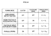
- Fig. 4 shows various combinations of ON and OFF between the clutch 5B and the clutch disc brake 5C depending on the driving condition of the hybrid vehicle 50B.
- the hybrid ECU 23B controls the actuator 33B to set both the clutch 5B and the clutch disc brake 5C to OFF, so as to put the hybrid vehicle 50B into a series driving mode (motor traction).
- V1 the second vehicle speed
- the hybrid ECU 23B controls the inverter 21 to stop operation of the motor 8, and drives the hybrid vehicle 50B at the second reduction gear ratio, which provides higher fuel efficiency than that of the six-cylinder driving in direct-coupling with the engine 1 represented by the characteristic curve a.
- the actuator 33B controls the clutch 5B to be OFF and the clutch disc brake 5C to be ON, so as to boost rotation rate of the output shaft 2 by the planetary gears 10 and then transmit it to the output gear 12 (engine traction at an acceleration stage).
- the traction characteristics of the engine 1 at the maximum output are represented by the characteristic curve e of Fig. 2, in which necessary traction can be obtained without a full depression of the acceleration pedal.
- the vehicle speed reaches V2 at most as shown in Fig. 2, and the traction at V2 is smaller than the maximum vehicle speed V3 at the maximum output in the variable displacement of the direct coupling with the engine 1.
- the engine ECU 25 controls the engine 1 to perform the variable displacement operation.
- the hybrid ECU 23B controls the actuator 33B such that the clutch 5B is set to ON and the clutch disk brake 5B is set to OFF, so that the sun gear 15 and the planetary carrier 17 rotate together (driven by direct coupling with the engine 1). If a relatively smaller traction is required in a flat ground running or the like and the depression amount of the accelerator pedal becomes smaller, the hybrid ECU 23B determines that a smaller torque is required, so that the engine ECU 25 controls the engine 1 to perform low-output driving in the variable displacement, thereby to provide a low-output engine operation through the variable displacement on one bank side. Accordingly, the rotation of the output shaft 2 is transmitted to the output gear 12 in the direct coupling state without being reduced in rotational rate at the planetary gears 10.
- the motor 8 When the vehicle 50B is accelerated or decelerated within the moderate/higher vehicle speed range, the motor 8 performs an assist driving operation or a regenerative operation, as similar to the first embodiment.
- the hybrid ECU 23B performs the same control of the first embodiment. This means that the driving mode shifts to the parallel driving mode in which the motor 8 assists the driving of the engine 1.
- both the clutch 5B and the clutch disc brake 5C are set to "OFF" and the driving wheels 6 are driven by the motor 8 alone (series driving mode).
- the driving wheels 6 are basically driven by the engine 1 alone, and provided with an assist by the motor 8 if necessary when the vehicle 50B is accelerated.
- the driving wheels 6 are driven by the engine 1 together with the motor 8 (parallel driving mode).
- the hybrid vehicle 50B is operated in a steady driving state by the engine 1 alone, in which the first reduction gear ratio is defined for the vehicle speed range of V4 (first vehicle speed) lower than the maximum vehicle speed of Vmax.
- the characteristic curve a of the second embodiment represents a lower traction than a traction of the engine 1 represented by the characteristic curve f (conventional), in which the reduction gear ratio of the first transmission path is defined to achieve the maximum vehicle speed Vmax of the hybrid vehicle 50B by only using the traction of the engine 1, as disclosed in JPB2942533, as similar to the first embodiment.
- the second embodiment allows the engine 1 to operate with a lower rotational load relative to the same running resistance, thereby to enhance fuel efficiency more than a conventional hybrid vehicle. Furthermore, in a flat ground running that requires a smaller traction, as represented by the characteristic curve d, it is possible to utilize the traction characteristic of the variable displacement operation, which contributes to a steady running with higher fuel efficiency.
- the hybrid vehicle 50B has a large displacement volume engine as the engine 1
- an excess traction becomes greater in the steady running and the transmission gears 9B is defined to have a higher ratio than that of the above mentioned conventional hybrid vehicle, thereby to enhance fuel efficiency significantly, compared to the conventional case.
- the output characteristic variable mechanism 31 including a variable displacement function and the like may be incorporated in the engine 1, so as to enhance fuel efficiency.
- the second reduction gear ratio is defined to be smaller than the first reduction gear ratio so that the vehicle speed becomes V2, which is lower than V3 that can be achieved at the maximum output at the first reduction gear ratio when the output of the engine 1 is lowered by the output characteristics valuable mechanism 31.
- the vehicle speed can be shifted to the second reduction gear ratio that provides a smaller traction at the vehicle speed V2, thereby to provide an engine rotational rate with higher fuel efficiency in a steady running at a lower speed.
- the transmission of the traction from the engine 1 is disconnected by setting the clutch 5B to OFF, and drives the driving wheels 6 by the traction from the motor 8, so that the hybrid vehicle 50B can run with a greater traction of the motor 8. Accordingly, it is possible to reflect on the vehicle driving the driver's will that he or she wants to drive the vehicle 50B with a greater traction, which is indicated by the driver's moving the shift lever to the "L" range.
- the motor 8 is used as an assist of the engine driving for the parallel driving, as mentioned above.
- the series driving may be applicable, in which the first transmission path of the engine 1 is disconnected and the engine 1 drives the generator 4 to generate power that drives the motor 8.
- the motor axis 8a is directly coupled with the main gear 11.
- the traction may be transmitted via the input gear 8b provided at the motor axis 8a to the main gear 11, as similar to the first embodiment.
- the highest vehicle speed range (first vehicle speed range) is defined as V4 or more.
- an upper limit of the moderate/higher vehicle speed range (second vehicle speed range) may be defined as an appropriate vehicle speed value lower than V4 at which fuel efficiency becomes higher, so as to lower the vehicle speed value for switching to the assist driving operation by the motor 8 or to the series driving mode.
- the traction of the motor 8 is transmitted to the main gear 11 through the input gear 8b provided with the motor axis 8a, or is transmitted to the main gear 11 that directly couples with the motor axis 8a; and the traction of the motor 8 covers the vehicle speed range from 0 to less than V1 and the vehicle speed range from V4 to the maximum vehicle speed Vmax.
- the rotational rate of the motor 8 may exceed 10,000 rpm. It is easy to control the inverter 21 to make the motor 8 rotate at a higher rate. However, this may cause more sever design requirements on mechanical structures for rotors or bearings of the motor 8, etc.; and if rigidity of the motor 8 is enhanced, increase in weight thereof may occur.
- the motor axis 8a may be provided with a two-stage transmission mechanism so that the rotational rate of the motor axis 8a can be shifted between "direct coupling” and “acceleration”, whereby rotation of the motor 8 is transmitted to the main gear 11 through such an output axis of the two-stage transmission mechanism.
- the hybrid ECU 24A or the hybrid ECU 24B selects a speed shift on the two-stage transmission mechanism such that the "direct coupling" stage is selected in the vehicle speed range from 0 to less than V1, and the "acceleration" stage is selected in the vehicle speed range from V4 to Vmax, thereby to enable a driving operation in which the rotation rate of the motor 8 is decreased in the vehicle speed range from V4 to Vmax.
- Fig. 7 is a schematic diagram for explaining an essential part of another variation of the first and second embodiments.
- a mechanically direct-coupled dog clutch 5C instead of using the clutch 5A or 5B, as well as an electric actuator 33C that drives the dog clutch 5C.
- the electric actuator 33C controls ON/OFF of the mechanically direct-coupled dog clutch 5C.
Applications Claiming Priority (2)
| Application Number | Priority Date | Filing Date | Title |
|---|---|---|---|
| JP2006184565A JP4217253B2 (ja) | 2006-07-04 | 2006-07-04 | ハイブリッド車両 |
| JP2006184475A JP4217252B2 (ja) | 2006-07-04 | 2006-07-04 | ハイブリッド車両 |
Publications (3)
| Publication Number | Publication Date |
|---|---|
| EP1876050A2 true EP1876050A2 (fr) | 2008-01-09 |
| EP1876050A3 EP1876050A3 (fr) | 2008-02-20 |
| EP1876050B1 EP1876050B1 (fr) | 2010-09-22 |
Family
ID=38535274
Family Applications (1)
| Application Number | Title | Priority Date | Filing Date |
|---|---|---|---|
| EP07110944A Expired - Fee Related EP1876050B1 (fr) | 2006-07-04 | 2007-06-25 | Véhicule hybride |
Country Status (3)
| Country | Link |
|---|---|
| US (1) | US8028779B2 (fr) |
| EP (1) | EP1876050B1 (fr) |
| DE (1) | DE602007009340D1 (fr) |
Cited By (2)
| Publication number | Priority date | Publication date | Assignee | Title |
|---|---|---|---|---|
| WO2014155263A1 (fr) * | 2013-03-28 | 2014-10-02 | Tata Motors Limited | Groupe motopropulseur pour un véhicule hybride et procédé associé |
| CN114368275A (zh) * | 2021-11-08 | 2022-04-19 | 浙江零跑科技股份有限公司 | 一种混合动力总成结构及其工作方法 |
Families Citing this family (19)
| Publication number | Priority date | Publication date | Assignee | Title |
|---|---|---|---|---|
| US7543454B2 (en) * | 2005-03-14 | 2009-06-09 | Zero Emission Systems, Inc. | Method and auxiliary system for operating a comfort subsystem for a vehicle |
| US7600595B2 (en) * | 2005-03-14 | 2009-10-13 | Zero Emission Systems, Inc. | Electric traction |
| US7921945B2 (en) * | 2006-02-21 | 2011-04-12 | Clean Emissions Technologies, Inc. | Vehicular switching, including switching traction modes and shifting gears while in electric traction mode |
| US8565969B2 (en) | 2007-04-03 | 2013-10-22 | Clean Emissions Technologies, Inc. | Over the road/traction/cabin comfort retrofit |
| JP4217258B2 (ja) * | 2006-09-21 | 2009-01-28 | 本田技研工業株式会社 | ハイブリッド車両 |
| US7921950B2 (en) * | 2006-11-10 | 2011-04-12 | Clean Emissions Technologies, Inc. | Electric traction retrofit |
| US7983823B2 (en) * | 2007-09-11 | 2011-07-19 | GM Global Technology Operations LLC | Method and control architecture for selection of optimal engine input torque for a powertrain system |
| US20090187298A1 (en) * | 2008-01-18 | 2009-07-23 | Cuppetilli Robert D | Vehicle propulsion arrangement |
| AU2008352923B2 (en) * | 2008-03-19 | 2014-04-03 | Clean Emissions Technologies, Inc. | Electric traction system and method |
| US9758146B2 (en) * | 2008-04-01 | 2017-09-12 | Clean Emissions Technologies, Inc. | Dual mode clutch pedal for vehicle |
| JP2012531354A (ja) * | 2009-06-25 | 2012-12-10 | フィスカー オートモーティブ インコーポレイテッド | マルチモーターハイブリッドドライブシステムのための直接的な電気的接続 |
| US9631528B2 (en) | 2009-09-03 | 2017-04-25 | Clean Emissions Technologies, Inc. | Vehicle reduced emission deployment |
| JP5201190B2 (ja) | 2010-10-08 | 2013-06-05 | 三菱自動車工業株式会社 | ハイブリット車のクラッチ制御装置 |
| US8657045B2 (en) * | 2012-07-02 | 2014-02-25 | Ford Global Technologies, Llc | Hybrid vehicle and associated engine speed control method |
| US9481351B2 (en) | 2012-07-02 | 2016-11-01 | Ford Global Technologies, Llc | Hybrid vehicle and associated engine start and stop control method |
| US9352737B2 (en) * | 2012-10-08 | 2016-05-31 | Ford Global Technologies, Llc | Method and system for operating a hybrid powertrain |
| CA2889837C (fr) * | 2012-11-06 | 2017-03-21 | Honda Motor Co., Ltd. | Dispositif de detection de mauvais fonctionnement et vehicule hybride |
| WO2017023854A1 (fr) | 2015-07-31 | 2017-02-09 | Massachusetts Institute Of Technology | Changement de vitesse automatisée d'une transmission manuelle |
| WO2017192913A1 (fr) | 2016-05-04 | 2017-11-09 | Massachusetts Institute Of Technology | Transmission hybride sans embrayage à deux arbres |
Citations (1)
| Publication number | Priority date | Publication date | Assignee | Title |
|---|---|---|---|---|
| US5775449A (en) | 1994-06-06 | 1998-07-07 | Kabushikikaisha Equos Research | Hybrid vehicle |
Family Cites Families (20)
| Publication number | Priority date | Publication date | Assignee | Title |
|---|---|---|---|---|
| JPS55127221A (en) | 1979-03-20 | 1980-10-01 | Daihatsu Motor Co Ltd | Driving system of vehicle |
| DE19709457A1 (de) | 1997-03-07 | 1998-09-10 | Mannesmann Sachs Ag | Antriebsanordnung für ein Kraftfahrzeug |
| JP3096446B2 (ja) | 1997-09-17 | 2000-10-10 | 本田技研工業株式会社 | ハイブリッド車両の制御装置 |
| US6048288A (en) * | 1997-11-18 | 2000-04-11 | Toyota Jidosha Kabushiki Kaisha | Power train system for a vehicle and method for operating same |
| US5943918A (en) * | 1997-12-01 | 1999-08-31 | Chrysler Corporation | Powertrain system for a hybrid electric vehicle |
| US6110066A (en) * | 1998-02-05 | 2000-08-29 | Southwest Research Institute | Parallel hybrid drivetrain |
| EP0990793B1 (fr) * | 1998-09-28 | 2004-08-25 | Toyota Jidosha Kabushiki Kaisha | Dispositif d'arrêt et de redémarrage pour moteur de véhicule |
| JP2000257462A (ja) * | 1999-03-09 | 2000-09-19 | Honda Motor Co Ltd | ハイブリッド車両のエンジン制御装置 |
| FR2796339B1 (fr) * | 1999-07-13 | 2001-10-05 | Peugeot Citroen Automobiles Sa | Boite de vitesses mecanique en ligne, pour vehicule a propulsion hybride |
| JP3909644B2 (ja) * | 1999-12-27 | 2007-04-25 | アイシン・エィ・ダブリュ株式会社 | ハイブリッド駆動装置 |
| JP4576714B2 (ja) * | 2000-12-28 | 2010-11-10 | アイシン・エィ・ダブリュ株式会社 | オイルポンプの駆動制御装置 |
| JP3521873B2 (ja) * | 2001-01-17 | 2004-04-26 | トヨタ自動車株式会社 | 車両用自動変速機の油圧制御装置 |
| US6644427B2 (en) * | 2001-04-06 | 2003-11-11 | Ise Research Corporation | System and method for providing parallel power in a hybrid-electric vehicle |
| JP2004190845A (ja) * | 2002-12-13 | 2004-07-08 | Shin Caterpillar Mitsubishi Ltd | 作業機械の駆動装置 |
| US7028794B2 (en) * | 2003-02-26 | 2006-04-18 | Mitsubishi Denki Kabushiki Kaisha | Transmission gear apparatus for motor vehicle |
| JP3926774B2 (ja) * | 2003-07-04 | 2007-06-06 | 本田技研工業株式会社 | ハイブリッド車両の制御装置 |
| JP3620541B2 (ja) | 2003-09-05 | 2005-02-16 | トヨタ自動車株式会社 | ハイブリッド車両の駆動制御装置 |
| JP2006184565A (ja) | 2004-12-27 | 2006-07-13 | Seiko Precision Inc | 光学モジュールおよびこれを備えた撮影装置 |
| JP2006184475A (ja) | 2004-12-27 | 2006-07-13 | Ricoh Co Ltd | 記録体搬送装置及び画像形成装置 |
| US7282004B2 (en) * | 2005-08-30 | 2007-10-16 | Gm Global Technology Operations, Inc. | Electrically variable transmission having three interconnected planetary gearsets, a stationary member and a fixed input |
-
2007
- 2007-06-25 DE DE602007009340T patent/DE602007009340D1/de active Active
- 2007-06-25 EP EP07110944A patent/EP1876050B1/fr not_active Expired - Fee Related
- 2007-06-29 US US11/819,839 patent/US8028779B2/en active Active
Patent Citations (1)
| Publication number | Priority date | Publication date | Assignee | Title |
|---|---|---|---|---|
| US5775449A (en) | 1994-06-06 | 1998-07-07 | Kabushikikaisha Equos Research | Hybrid vehicle |
Cited By (2)
| Publication number | Priority date | Publication date | Assignee | Title |
|---|---|---|---|---|
| WO2014155263A1 (fr) * | 2013-03-28 | 2014-10-02 | Tata Motors Limited | Groupe motopropulseur pour un véhicule hybride et procédé associé |
| CN114368275A (zh) * | 2021-11-08 | 2022-04-19 | 浙江零跑科技股份有限公司 | 一种混合动力总成结构及其工作方法 |
Also Published As
| Publication number | Publication date |
|---|---|
| EP1876050B1 (fr) | 2010-09-22 |
| DE602007009340D1 (de) | 2010-11-04 |
| US8028779B2 (en) | 2011-10-04 |
| EP1876050A3 (fr) | 2008-02-20 |
| US20080006467A1 (en) | 2008-01-10 |
Similar Documents
| Publication | Publication Date | Title |
|---|---|---|
| EP1876050B1 (fr) | Véhicule hybride | |
| CN101108586B (zh) | 混合动力车辆 | |
| US7749130B2 (en) | Vehicle, driving system, and control methods of the same | |
| EP1297981B1 (fr) | Véhicule hybride avec train épicycloidal pour la répartition de la puissance | |
| US7766789B2 (en) | Control device for hybrid vehicle drive apparatus | |
| US7056260B2 (en) | Drive unit for vehicle | |
| US7980990B2 (en) | Power output apparatus, vehicle including power output apparatus, and control unit and method for power output apparatus | |
| US7137924B2 (en) | Control system for hybrid vehicles | |
| EP0953467B1 (fr) | Dispositif de transmission de puissance pour véhicule automobile | |
| EP1797352B1 (fr) | Vehicule hybride et procede de commande associe | |
| US7846051B2 (en) | Hybrid powertrain with an engine input clutch and method of control | |
| US7219756B2 (en) | Method for setting an operating point of a hybrid drive of a vehicle | |
| US8177005B2 (en) | Vehicle, driving device and control method thereof | |
| CA2666416C (fr) | Vehicule et son procede de commande | |
| US20090314560A1 (en) | Power output apparatus and hybrid vehicle | |
| EP2048018B1 (fr) | Dispositif de production de puissance, véhicule associé, et procédé de commande dudit dispositif | |
| US20080254934A1 (en) | Control device for hybrid vehicle drive apparatus | |
| US8126622B2 (en) | Control device for vehicular power transmitting apparatus | |
| US6890283B2 (en) | Control apparatus for controlling transmission of hybrid vehicle | |
| US8630778B2 (en) | Controlling a throttle for fuel cut acquisition | |
| CN101396960A (zh) | 混合动力系及其操作方法 | |
| US20100279817A1 (en) | Hybrid powertrain and method of operating same | |
| CN109229089A (zh) | 用于启动车辆混合动力传动系统的系统和方法 | |
| US7762921B2 (en) | Powertrain and method of controlling powertrain | |
| JP4217252B2 (ja) | ハイブリッド車両 |
Legal Events
| Date | Code | Title | Description |
|---|---|---|---|
| PUAI | Public reference made under article 153(3) epc to a published international application that has entered the european phase |
Free format text: ORIGINAL CODE: 0009012 |
|
| 17P | Request for examination filed |
Effective date: 20070625 |
|
| AK | Designated contracting states |
Kind code of ref document: A2 Designated state(s): AT BE BG CH CY CZ DE DK EE ES FI FR GB GR HU IE IS IT LI LT LU LV MC MT NL PL PT RO SE SI SK TR |
|
| AX | Request for extension of the european patent |
Extension state: AL BA HR MK YU |
|
| PUAL | Search report despatched |
Free format text: ORIGINAL CODE: 0009013 |
|
| AK | Designated contracting states |
Kind code of ref document: A3 Designated state(s): AT BE BG CH CY CZ DE DK EE ES FI FR GB GR HU IE IS IT LI LT LU LV MC MT NL PL PT RO SE SI SK TR |
|
| AX | Request for extension of the european patent |
Extension state: AL BA HR MK YU |
|
| RIC1 | Information provided on ipc code assigned before grant |
Ipc: B60K 6/445 20071001AFI20071016BHEP Ipc: B60K 6/50 20071001ALI20080117BHEP Ipc: B60W 30/18 20060101ALI20080117BHEP Ipc: B60W 10/10 20060101ALI20080117BHEP Ipc: B60W 10/30 20060101ALI20080117BHEP |
|
| 17Q | First examination report despatched |
Effective date: 20080416 |
|
| AKX | Designation fees paid |
Designated state(s): DE FR GB |
|
| GRAP | Despatch of communication of intention to grant a patent |
Free format text: ORIGINAL CODE: EPIDOSNIGR1 |
|
| RIN1 | Information on inventor provided before grant (corrected) |
Inventor name: URANO, JUNJIC/O HONDA R&D CO., LTD. Inventor name: YUMOTO, TOSHIYUKIC/O HONDA R&D CO., LTD. Inventor name: MORISHITA, NAOHISAC/O HONDA R&D CO., LTD. Inventor name: HONDA, KENJIC/O HONDA R&D CO., LTD. Inventor name: IWATA, KAZUYUKIC/O HONDA R&D CO., LTD. |
|
| GRAS | Grant fee paid |
Free format text: ORIGINAL CODE: EPIDOSNIGR3 |
|
| GRAA | (expected) grant |
Free format text: ORIGINAL CODE: 0009210 |
|
| AK | Designated contracting states |
Kind code of ref document: B1 Designated state(s): DE FR GB |
|
| REG | Reference to a national code |
Ref country code: GB Ref legal event code: FG4D |
|
| REF | Corresponds to: |
Ref document number: 602007009340 Country of ref document: DE Date of ref document: 20101104 Kind code of ref document: P |
|
| PLBE | No opposition filed within time limit |
Free format text: ORIGINAL CODE: 0009261 |
|
| STAA | Information on the status of an ep patent application or granted ep patent |
Free format text: STATUS: NO OPPOSITION FILED WITHIN TIME LIMIT |
|
| 26N | No opposition filed |
Effective date: 20110623 |
|
| REG | Reference to a national code |
Ref country code: DE Ref legal event code: R097 Ref document number: 602007009340 Country of ref document: DE Effective date: 20110623 |
|
| REG | Reference to a national code |
Ref country code: GB Ref legal event code: 746 Effective date: 20140128 |
|
| REG | Reference to a national code |
Ref country code: DE Ref legal event code: R084 Ref document number: 602007009340 Country of ref document: DE Effective date: 20140204 |
|
| REG | Reference to a national code |
Ref country code: FR Ref legal event code: PLFP Year of fee payment: 10 |
|
| REG | Reference to a national code |
Ref country code: FR Ref legal event code: PLFP Year of fee payment: 11 |
|
| REG | Reference to a national code |
Ref country code: FR Ref legal event code: PLFP Year of fee payment: 12 |
|
| PGFP | Annual fee paid to national office [announced via postgrant information from national office to epo] |
Ref country code: FR Payment date: 20180511 Year of fee payment: 12 |
|
| PGFP | Annual fee paid to national office [announced via postgrant information from national office to epo] |
Ref country code: GB Payment date: 20180403 Year of fee payment: 12 |
|
| PGFP | Annual fee paid to national office [announced via postgrant information from national office to epo] |
Ref country code: DE Payment date: 20190612 Year of fee payment: 13 |
|
| GBPC | Gb: european patent ceased through non-payment of renewal fee |
Effective date: 20190625 |
|
| PG25 | Lapsed in a contracting state [announced via postgrant information from national office to epo] |
Ref country code: GB Free format text: LAPSE BECAUSE OF NON-PAYMENT OF DUE FEES Effective date: 20190625 |
|
| PG25 | Lapsed in a contracting state [announced via postgrant information from national office to epo] |
Ref country code: FR Free format text: LAPSE BECAUSE OF NON-PAYMENT OF DUE FEES Effective date: 20190630 |
|
| REG | Reference to a national code |
Ref country code: DE Ref legal event code: R119 Ref document number: 602007009340 Country of ref document: DE |
|
| PG25 | Lapsed in a contracting state [announced via postgrant information from national office to epo] |
Ref country code: DE Free format text: LAPSE BECAUSE OF NON-PAYMENT OF DUE FEES Effective date: 20210101 |