EP1874062A1 - Optical system for a projector, and corresponding projector - Google Patents
Optical system for a projector, and corresponding projector Download PDFInfo
- Publication number
- EP1874062A1 EP1874062A1 EP07111183A EP07111183A EP1874062A1 EP 1874062 A1 EP1874062 A1 EP 1874062A1 EP 07111183 A EP07111183 A EP 07111183A EP 07111183 A EP07111183 A EP 07111183A EP 1874062 A1 EP1874062 A1 EP 1874062A1
- Authority
- EP
- European Patent Office
- Prior art keywords
- colour
- illumination
- polarized
- splitter
- projector
- Prior art date
- Legal status (The legal status is an assumption and is not a legal conclusion. Google has not performed a legal analysis and makes no representation as to the accuracy of the status listed.)
- Withdrawn
Links
- 230000003287 optical effect Effects 0.000 title claims abstract description 15
- 238000005286 illumination Methods 0.000 claims abstract description 35
- 238000003384 imaging method Methods 0.000 claims description 30
- 239000003086 colorant Substances 0.000 claims description 12
- 230000000295 complement effect Effects 0.000 claims description 4
- 230000010287 polarization Effects 0.000 description 24
- 238000000034 method Methods 0.000 description 3
- 230000003042 antagnostic effect Effects 0.000 description 2
- 239000004973 liquid crystal related substance Substances 0.000 description 2
- 238000006243 chemical reaction Methods 0.000 description 1
- 230000001149 cognitive effect Effects 0.000 description 1
- 230000000694 effects Effects 0.000 description 1
- 230000004907 flux Effects 0.000 description 1
- 229910052710 silicon Inorganic materials 0.000 description 1
- 239000010703 silicon Substances 0.000 description 1
- 230000001360 synchronised effect Effects 0.000 description 1
- 230000000007 visual effect Effects 0.000 description 1
Images

Classifications
-
- G—PHYSICS
- G02—OPTICS
- G02B—OPTICAL ELEMENTS, SYSTEMS OR APPARATUS
- G02B27/00—Optical systems or apparatus not provided for by any of the groups G02B1/00 - G02B26/00, G02B30/00
- G02B27/10—Beam splitting or combining systems
-
- H—ELECTRICITY
- H04—ELECTRIC COMMUNICATION TECHNIQUE
- H04N—PICTORIAL COMMUNICATION, e.g. TELEVISION
- H04N9/00—Details of colour television systems
- H04N9/12—Picture reproducers
- H04N9/31—Projection devices for colour picture display, e.g. using electronic spatial light modulators [ESLM]
- H04N9/3141—Constructional details thereof
- H04N9/315—Modulator illumination systems
-
- G—PHYSICS
- G02—OPTICS
- G02B—OPTICAL ELEMENTS, SYSTEMS OR APPARATUS
- G02B27/00—Optical systems or apparatus not provided for by any of the groups G02B1/00 - G02B26/00, G02B30/00
- G02B27/10—Beam splitting or combining systems
- G02B27/1006—Beam splitting or combining systems for splitting or combining different wavelengths
- G02B27/102—Beam splitting or combining systems for splitting or combining different wavelengths for generating a colour image from monochromatic image signal sources
- G02B27/1026—Beam splitting or combining systems for splitting or combining different wavelengths for generating a colour image from monochromatic image signal sources for use with reflective spatial light modulators
-
- G—PHYSICS
- G02—OPTICS
- G02B—OPTICAL ELEMENTS, SYSTEMS OR APPARATUS
- G02B27/00—Optical systems or apparatus not provided for by any of the groups G02B1/00 - G02B26/00, G02B30/00
- G02B27/10—Beam splitting or combining systems
- G02B27/1006—Beam splitting or combining systems for splitting or combining different wavelengths
- G02B27/102—Beam splitting or combining systems for splitting or combining different wavelengths for generating a colour image from monochromatic image signal sources
- G02B27/1046—Beam splitting or combining systems for splitting or combining different wavelengths for generating a colour image from monochromatic image signal sources for use with transmissive spatial light modulators
-
- G—PHYSICS
- G02—OPTICS
- G02B—OPTICAL ELEMENTS, SYSTEMS OR APPARATUS
- G02B27/00—Optical systems or apparatus not provided for by any of the groups G02B1/00 - G02B26/00, G02B30/00
- G02B27/10—Beam splitting or combining systems
- G02B27/14—Beam splitting or combining systems operating by reflection only
- G02B27/145—Beam splitting or combining systems operating by reflection only having sequential partially reflecting surfaces
-
- G—PHYSICS
- G02—OPTICS
- G02B—OPTICAL ELEMENTS, SYSTEMS OR APPARATUS
- G02B27/00—Optical systems or apparatus not provided for by any of the groups G02B1/00 - G02B26/00, G02B30/00
- G02B27/18—Optical systems or apparatus not provided for by any of the groups G02B1/00 - G02B26/00, G02B30/00 for optical projection, e.g. combination of mirror and condenser and objective
-
- G—PHYSICS
- G02—OPTICS
- G02B—OPTICAL ELEMENTS, SYSTEMS OR APPARATUS
- G02B27/00—Optical systems or apparatus not provided for by any of the groups G02B1/00 - G02B26/00, G02B30/00
- G02B27/28—Optical systems or apparatus not provided for by any of the groups G02B1/00 - G02B26/00, G02B30/00 for polarising
- G02B27/283—Optical systems or apparatus not provided for by any of the groups G02B1/00 - G02B26/00, G02B30/00 for polarising used for beam splitting or combining
-
- H—ELECTRICITY
- H04—ELECTRIC COMMUNICATION TECHNIQUE
- H04N—PICTORIAL COMMUNICATION, e.g. TELEVISION
- H04N9/00—Details of colour television systems
- H04N9/12—Picture reproducers
- H04N9/31—Projection devices for colour picture display, e.g. using electronic spatial light modulators [ESLM]
- H04N9/3102—Projection devices for colour picture display, e.g. using electronic spatial light modulators [ESLM] using two-dimensional electronic spatial light modulators
- H04N9/3111—Projection devices for colour picture display, e.g. using electronic spatial light modulators [ESLM] using two-dimensional electronic spatial light modulators for displaying the colours sequentially, e.g. by using sequentially activated light sources
- H04N9/3114—Projection devices for colour picture display, e.g. using electronic spatial light modulators [ESLM] using two-dimensional electronic spatial light modulators for displaying the colours sequentially, e.g. by using sequentially activated light sources by using a sequential colour filter producing one colour at a time
-
- G—PHYSICS
- G02—OPTICS
- G02B—OPTICAL ELEMENTS, SYSTEMS OR APPARATUS
- G02B26/00—Optical devices or arrangements for the control of light using movable or deformable optical elements
- G02B26/007—Optical devices or arrangements for the control of light using movable or deformable optical elements the movable or deformable optical element controlling the colour, i.e. a spectral characteristic, of the light
- G02B26/008—Optical devices or arrangements for the control of light using movable or deformable optical elements the movable or deformable optical element controlling the colour, i.e. a spectral characteristic, of the light in the form of devices for effecting sequential colour changes, e.g. colour wheels
Definitions
- the invention relates to the field of image projection.
- the invention relates to an imaging illumination system in a video projector of the front-projection type or in a back-projector.
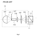
- an illumination system 10 illuminating an imager 11 is used.
- the illumination system 10 comprises:
- the illumination source 100 illuminates, with a light beam 101, the colour wheel 107 placed at the entrance of the rectangular guide 102, at the focus of the elliptical reflector of the source 100.
- the rectangular guide 102 is used to convert the circular cross section of the illumination beam into a rectangular cross section and to make the beam spatially uniform.
- the exit of the guide 102 is imaged on the imager 11 via the system of relay lenses, a minimum number of lenses being two, but often there being three or four lenses, the illumination moreover being preferably telecentric.
- a TIR prism 12 is placed between the illumination system 10 and the imager 11 in order to split the illumination and imaging beams.
- the TIR prism 12 is unnecessary if the imager 11 is of the transmissive LCD (Liquid Crystal Display) type or is replaced with a dichroic PBS (Polarizing Beam Splitter) if the imager 11 is of the LCOS (Liquid Crystal On Silicon) type.
- LCOS Liquid Crystal On Silicon
- the object of the invention is to alleviate these drawbacks of the
- the objective of the invention is to provide a more powerful imaging flux, while still remaining relatively inexpensive.
- the invention provides an optical system for a projector, comprising:
- the two polarizations of the incident beam are used, thus minimizing the number of components in the optical illumination/imaging system.
- the system includes at least a second polarizing beam splitter suitable for combining the first imaging beam with the second imaging beam in order to form a third imaging beam.
- the two separate regions are associated, at each instant, with colour segments of different colours.
- the two separate regions are associated, at each instant, with colour segments of complementary colours.
- the other region is associated with a colour segment of red colour, and in that, at the instances when one of said two regions is associated with a colour segment of yellow colour, the other region is associated with a colour segment of blue colour.
- the first and second imagers are of the LCOS or transmissive LCD type.
- the first polarizing beam splitter is of the grating polarizer type or dichroic type.
- the invention also relates to a projector comprising an optical system according to the invention as presented above.
- Figure 2 is a highly schematic synoptic view of a back-projector 2 according to a first embodiment of the invention.
- the projector 2 comprises:
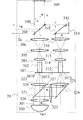
- FIG. 3 illustrates in detail the imaging system 20 with its imager (also called a micro display) of the LCOS type, which system comprises :
- the optical paths travelled by the beams between the entrance of the respective guides 302 and 312 and the entry of the objective 21 are the same (in other words, the distances d separating the splitter 318 from the respective imagers 309 and 319 are the same).
- the optical assembly comprising the source 300 and the lenses 320 and 326 allows the beam 326 to be focused near the colour wheel 307 at the entry of the guide 302 onto the point 3070.
- the position of the lamp in the source 300, the shape of the reflector (for example parabolic or elliptical shape, the lamp being placed at the focus) and the shape and position of the lenses 320 and 326 are adapted so as to focus the beam onto the point 3070.
- the optical assembly comprising the source 300, the splitter 321, the mirror 324 and the lenses 320, 323 and 325 allows the beam 327 to be focused near the colour wheel 307 at the entry of the guide 312 onto the point 3071.
- the position of the lamp in the source 300, the shape of the reflector, the position and orientation of the splitter 321 and of the mirror 324 and the shape and position of the lenses 320, 323 and 325 are adapted so as to focus the beam onto the point 3071.
- the splitter 308 Since the polarization of the beam 340 is vertical (after change in polarization of the horizontally-polarized beam 326), it is reflected by the splitter 308.
- the polarization of the beam 341 is horizontal (after the change in polarization of the vertically-polarized beam 327), it is transmitted by the splitter 318 and then by the splitter 308, which is also placed in the path of the beam 341.
- the two beams 340 and 341 then combine to form a single imaging beam 34.
- the colour wheel 307 comprises several (for example 3, 4, 5 or 6) colour segments.
- the focal points 3070 and 3071 are sufficiently far apart to allow easy mechanical positioning of the optical elements 321 to 325, 302, 312, 304 to 306 and 314 to 316.
- the two focal points are such that they allow the beams 326 and 327 to cut the wheel in two regions belonging to segments of different colours.
- the two regions are, for example opposed relative to the axis of rotation 3072 of the wheel 307.
- the two regions are placed at the same distance from the axis 3072 along radii of the wheel 307 that make an angle of 120° between them.
- the beams 340 and 341 are of different colours at a given instant.
- the beam 340 is red (respectively blue, red) when the beam 341 is green or blue (respectively green or red, green or blue).
- the colour wheel 307 comprises six segments of respective colours red, green, blue, cyan, magenta and yellow.
- the beams 326 and 327 cut the wheel in segments of complementary colours.
- Red (respectively blue, green) is complementary with cyan, (respectively yellow, magenta).
- An anti-pirating system is described in the patent application published under reference WO05/027529 and entitled "Methods of processing and displaying images and display device using the methods".
- an image display method is employed on the basis of at least one source image in which a plurality of images are displayed in succession and in which, in at least one pixel, the colour of the displayed images is different from the colour in the source image, and the resultant of the colours of the displayed images is the colour in the source image.
- the colour wheel 307 comprises at least four segments of respective colours red, green, blue and yellow.
- the beams 326 and 327 cut the wheel in segments having colours that are antagonistic in respect of the human cognitive and visual system. Red (respectively blue) is antagonistic vis-à-vis with green (respectively yellow).
- one, two or three grating splitters 321, 308 and 318 are replaced with other types of splitters, for example a polarizing splitter plate or a PBS (Polarizing Beam Splitter) cube (a polarization p replacing the horizontal polarization and a polarization s replacing the vertical polarization, these polarizations both being linear).
- a polarizing splitter plate or a PBS (Polarizing Beam Splitter) cube a polarization p replacing the horizontal polarization and a polarization s replacing the vertical polarization, these polarizations both being linear.
- the elements of the imaging system 20 have been shown in exploded form.
- the mirror 324 may be brought closer to the splitter 321 so that the elements 302, 304 to 306 and 308 are closer to, but without intersecting, the elements 312, 314 to 316 and 318.
- the imager 319 may be tangential to the splitter 318 (or may be affixed thereto if they are dichroic PBS splitters of cubic shape).
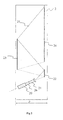
- FIG. 4 illustrates in detail an imaging system 4 with imagers 400 and 402 of the transmissive LCD type.
- the system 4 replaces the system 20 in the projector 2 illustrated with regard to Figure 2. It comprises common elements, which bear the same references and will not be described further, in particular the source 300, the lenses 320, 322, 323, 325, 304 to 306 and 314 to 316, the splitter 321, the mirror 324, the wheel 307 and the guides 302 and 312.
- p-polarized i.e. linear polarization
- the beam 440 is reflected by a polarizing beam splitter 401 of the dichroic PBS type, as illustrated.
- the splitter 401 is replaced with other types of splitter, for example a polarizing splitter plate or a grating polarizer.
- the beam 327 collimated by the lenses 314 to 316 illuminates the LCD imager 402, which creates a p-polarized imaging beam 441.
- the beam 441 is reflected by the mirror 403 inclined at 45° to the axis of the beam 441 and passes through the polarizing beam splitter 401.
- the two beams 440 and 441 then combine to form a single imaging beam 44.
- the distances separating the splitter 401 from the respective imagers 400 and 402 are the same.
- the invention applies to other types of imagers and especially to DMD-type imagers.
- the splitter 318 may be replaced with a first TIR-type beam splitter and the imager 319 may be replaced with a first DMD imager; behind the lens 306, the elements 308 and 309 are replaced with a mirror that reflects the beam along a perpendicular direction in order to illuminate a second beam splitter of the TIR type associated with a second DMD imager; each imaging beam thus created passes through a TIR splitter and the two differently polarized beams are then recombined in a polarizing beam splitter in order to form a single imaging beam.
- the rectangular guides may be replaced with guides having a non-rectangular cross section, or more generally with any type of means for converting the light source and/or for making it uniform, for example a free-form lens (as described in patent application WO 2006/058885 entitled "Optical system and corresponding optical element”.
- a free-form lens as described in patent application WO 2006/058885 entitled "Optical system and corresponding optical element”.
- the arrangement, the number and the shape of the optical elements for focusing or collimating the light beams are not limited to the examples described above. In fact these elements may be reduced or increased according to the various parameters associated with the space requirement, the optical quality and the size of the beams in particular.
- angles of inclination of the mirrors and of the beam splitters are not necessarily at 45° or 90° to the incident beams. According to the invention, they may take other values that make it possible to spatially split or, on the contrary, combine the illumination or imaging beams.
- a system according to the invention employs a single colour wheel, thereby facilitating its implementation.
- two synchronized wheels may be implemented, each of the differently polarized source beams passing through one of the wheels.
- any type of light source suitable for projection may be used, and in particular a light source with an elliptical reflector or a light source based on LEDs (light-emitting diodes).
- the invention also applies to an application of the three-dimension projection type. Specifically, using a first imager for an image associated with one polarization and one eye, and a second imager for an image associated with a second polarization and the other eye, spectacles in which the right lens filters a different polarization from that filtered by the left lens then permits vision in three dimensions (assuming, of course, that the imagers display images suitable for projection in three dimensions).
- the invention relates not only to an illumination/imaging system but also to a projector, in particular a back-projector or front projector) comprising such a system.
Landscapes
- Physics & Mathematics (AREA)
- General Physics & Mathematics (AREA)
- Optics & Photonics (AREA)
- Engineering & Computer Science (AREA)
- Multimedia (AREA)
- Signal Processing (AREA)
- Projection Apparatus (AREA)
- Liquid Crystal (AREA)
Applications Claiming Priority (1)
| Application Number | Priority Date | Filing Date | Title |
|---|---|---|---|
| FR0652724A FR2903199A1 (fr) | 2006-06-30 | 2006-06-30 | Systeme optique pour projecteur et projecteur correspondant |
Publications (1)
| Publication Number | Publication Date |
|---|---|
| EP1874062A1 true EP1874062A1 (en) | 2008-01-02 |
Family
ID=37865661
Family Applications (1)
| Application Number | Title | Priority Date | Filing Date |
|---|---|---|---|
| EP07111183A Withdrawn EP1874062A1 (en) | 2006-06-30 | 2007-06-27 | Optical system for a projector, and corresponding projector |
Country Status (6)
| Country | Link |
|---|---|
| US (1) | US7862182B2 (enExample) |
| EP (1) | EP1874062A1 (enExample) |
| JP (1) | JP5350610B2 (enExample) |
| KR (1) | KR101386961B1 (enExample) |
| CN (1) | CN101097296B (enExample) |
| FR (1) | FR2903199A1 (enExample) |
Cited By (1)
| Publication number | Priority date | Publication date | Assignee | Title |
|---|---|---|---|---|
| CN105676575A (zh) * | 2014-12-04 | 2016-06-15 | 欧司朗有限公司 | 用于投影或者照明装置的光模块 |
Families Citing this family (19)
| Publication number | Priority date | Publication date | Assignee | Title |
|---|---|---|---|---|
| WO2008076103A1 (en) * | 2006-12-18 | 2008-06-26 | Thomson Licensing | 2d/3d projector with rotating translucent cylinder for alternating light polarisation |
| US20100014008A1 (en) * | 2006-12-19 | 2010-01-21 | Youngshik Yoon | Wide color gaut high resolution dmd projection system |
| US8334935B2 (en) * | 2006-12-19 | 2012-12-18 | Thomson Licensing | High resolution DMD projection system |
| WO2008133611A1 (en) * | 2007-04-25 | 2008-11-06 | Thomson Licensing | High resolution 3d projection system |
| EP2160647A1 (en) * | 2007-06-25 | 2010-03-10 | Thomson Licensing | Video recording prevention system |
| WO2010062620A2 (en) * | 2008-10-27 | 2010-06-03 | Rpx Corporation | Image projection system for reducing spectral interference |
| CN102402018B (zh) * | 2010-09-07 | 2013-11-06 | 台达电子工业股份有限公司 | 偏极转换系统及其适用的立体投影光学系统 |
| JP2012113224A (ja) * | 2010-11-26 | 2012-06-14 | Sanyo Electric Co Ltd | 照明装置及び投写型映像表示装置 |
| TWI427397B (zh) * | 2011-03-23 | 2014-02-21 | 台達電子工業股份有限公司 | 光源系統 |
| CN102621697A (zh) * | 2012-03-09 | 2012-08-01 | 中国科学院长春光学精密机械与物理研究所 | 一种基于离轴反射结构的宽波段红外投影系统 |
| JP5174273B1 (ja) * | 2012-03-14 | 2013-04-03 | シャープ株式会社 | プロジェクタ |
| TWI489855B (zh) * | 2012-05-23 | 2015-06-21 | Delta Electronics Inc | 立體投影光源系統 |
| CN103713451B (zh) | 2012-09-28 | 2016-06-22 | 扬明光学股份有限公司 | 多重投影系统以及使用该系统的显示系统 |
| US9146452B2 (en) | 2013-03-12 | 2015-09-29 | Christie Digital Systems Usa, Inc. | Multi-color illumination apparatus |
| CN103472620B (zh) * | 2013-09-13 | 2016-03-16 | 合肥京东方光电科技有限公司 | 一种双屏幕显示装置 |
| CN104977700B (zh) * | 2014-04-10 | 2018-08-10 | 长春理工大学 | 一种用于dmd相机的光学系统 |
| CN107003181A (zh) * | 2015-01-23 | 2017-08-01 | 台湾超微光学股份有限公司 | 光谱仪及其光输入部 |
| US11950026B2 (en) * | 2017-04-14 | 2024-04-02 | Arizona Board Of Regents On Behalf Of The University Of Arizona | Methods and apparatus employing angular and spatial modulation of light |
| US11906769B2 (en) * | 2020-01-22 | 2024-02-20 | Sony Group Corporation | Optical system with polarization elements and multiple light valves |
Citations (8)
| Publication number | Priority date | Publication date | Assignee | Title |
|---|---|---|---|---|
| EP0372905A2 (en) * | 1988-12-05 | 1990-06-13 | Sharp Kabushiki Kaisha | Projection-type liquid crystal display apparatus |
| WO2001010137A1 (en) * | 1999-07-30 | 2001-02-08 | Koninklijke Philips Electronics N.V. | A two-panel projection system employing complementary illumination |
| EP1098537A2 (en) * | 1999-11-06 | 2001-05-09 | SAMSUNG ELECTRONICS Co. Ltd. | Projection display device using two liquid crystal display panels |
| EP1100259A2 (en) * | 1999-11-06 | 2001-05-16 | Samsung Electronics Co., Ltd. | False contour correction apparatus and method in an image display system |
| WO2001037576A1 (en) * | 1999-11-19 | 2001-05-25 | Unic View Ltd. | Sequential imaging system |
| US20040090601A1 (en) * | 2002-11-07 | 2004-05-13 | Nec Viewtechnology, Ltd. | Liquid crystal projector |
| US20040184005A1 (en) * | 2001-07-12 | 2004-09-23 | Shmuel Roth | Sequential projection color display using multiple imaging panels |
| FR2872924A1 (fr) * | 2004-07-06 | 2006-01-13 | Thomson Licensing Sa | Projecteur d'images numeriques pour grand ecran |
Family Cites Families (18)
| Publication number | Priority date | Publication date | Assignee | Title |
|---|---|---|---|---|
| JP3327153B2 (ja) * | 1995-12-18 | 2002-09-24 | セイコーエプソン株式会社 | 投射型表示装置 |
| US6147720A (en) * | 1995-12-27 | 2000-11-14 | Philips Electronics North America Corporation | Two lamp, single light valve projection system |
| US6247816B1 (en) * | 1997-08-07 | 2001-06-19 | International Business Machines Corporation | Optical system for projection displays using spatial light modulators |
| US5993007A (en) * | 1998-04-21 | 1999-11-30 | Samsung Electronics Co., Ltd. | Reflection type projector |
| US6666556B2 (en) * | 1999-07-28 | 2003-12-23 | Moxtek, Inc | Image projection system with a polarizing beam splitter |
| JP2002207192A (ja) * | 2001-01-04 | 2002-07-26 | Hitachi Ltd | 映像表示装置及び駆動回路 |
| US6547396B1 (en) * | 2001-12-27 | 2003-04-15 | Infocus Corporation | Stereographic projection system |
| US6646806B1 (en) * | 2002-05-17 | 2003-11-11 | Infocus Corporation | Polarized light source system with dual optical paths |
| KR20050085737A (ko) * | 2002-12-18 | 2005-08-29 | 코닌클리케 필립스 일렉트로닉스 엔.브이. | 4원색들을 포함하는 컬러-순차 투사 시스템 |
| JP4487543B2 (ja) * | 2003-12-03 | 2010-06-23 | ソニー株式会社 | 投影型画像表示装置 |
| JP2005286605A (ja) * | 2004-03-29 | 2005-10-13 | Nec Viewtechnology Ltd | 色輝度補正装置、該色輝度補正装置を備えたプロジェクタならびに色輝度補正方法 |
| EP1615449A3 (en) * | 2004-07-05 | 2006-10-25 | Thomson Licensing | Sequential colour display device |
| JP3901186B2 (ja) * | 2004-10-13 | 2007-04-04 | 松下電器産業株式会社 | 色順次カラー方式プロジェクタ装置 |
| US20060092380A1 (en) * | 2004-11-04 | 2006-05-04 | Salsman Kenneth E | Clean-up polarizer and gamma control for display system |
| JP2006163191A (ja) * | 2004-12-09 | 2006-06-22 | Canon Inc | 立体プロジェクタ |
| CN1847971B (zh) * | 2005-04-04 | 2010-05-12 | 中华映管股份有限公司 | 液晶投影显示器 |
| CN100345058C (zh) * | 2005-04-18 | 2007-10-24 | 东华大学 | 一种单芯片单色轮立体投影光学引擎 |
| JP2007248794A (ja) * | 2006-03-16 | 2007-09-27 | Hitachi Ltd | 投射型映像表示装置 |
-
2006
- 2006-06-30 FR FR0652724A patent/FR2903199A1/fr active Pending
-
2007
- 2007-06-08 KR KR1020070056180A patent/KR101386961B1/ko not_active Expired - Fee Related
- 2007-06-25 US US11/821,944 patent/US7862182B2/en not_active Expired - Fee Related
- 2007-06-27 EP EP07111183A patent/EP1874062A1/en not_active Withdrawn
- 2007-06-27 JP JP2007169112A patent/JP5350610B2/ja not_active Expired - Fee Related
- 2007-07-02 CN CN2007101273788A patent/CN101097296B/zh not_active Expired - Fee Related
Patent Citations (8)
| Publication number | Priority date | Publication date | Assignee | Title |
|---|---|---|---|---|
| EP0372905A2 (en) * | 1988-12-05 | 1990-06-13 | Sharp Kabushiki Kaisha | Projection-type liquid crystal display apparatus |
| WO2001010137A1 (en) * | 1999-07-30 | 2001-02-08 | Koninklijke Philips Electronics N.V. | A two-panel projection system employing complementary illumination |
| EP1098537A2 (en) * | 1999-11-06 | 2001-05-09 | SAMSUNG ELECTRONICS Co. Ltd. | Projection display device using two liquid crystal display panels |
| EP1100259A2 (en) * | 1999-11-06 | 2001-05-16 | Samsung Electronics Co., Ltd. | False contour correction apparatus and method in an image display system |
| WO2001037576A1 (en) * | 1999-11-19 | 2001-05-25 | Unic View Ltd. | Sequential imaging system |
| US20040184005A1 (en) * | 2001-07-12 | 2004-09-23 | Shmuel Roth | Sequential projection color display using multiple imaging panels |
| US20040090601A1 (en) * | 2002-11-07 | 2004-05-13 | Nec Viewtechnology, Ltd. | Liquid crystal projector |
| FR2872924A1 (fr) * | 2004-07-06 | 2006-01-13 | Thomson Licensing Sa | Projecteur d'images numeriques pour grand ecran |
Cited By (1)
| Publication number | Priority date | Publication date | Assignee | Title |
|---|---|---|---|---|
| CN105676575A (zh) * | 2014-12-04 | 2016-06-15 | 欧司朗有限公司 | 用于投影或者照明装置的光模块 |
Also Published As
| Publication number | Publication date |
|---|---|
| US7862182B2 (en) | 2011-01-04 |
| FR2903199A1 (fr) | 2008-01-04 |
| JP5350610B2 (ja) | 2013-11-27 |
| CN101097296B (zh) | 2011-12-14 |
| US20080094578A1 (en) | 2008-04-24 |
| KR101386961B1 (ko) | 2014-04-25 |
| KR20080003227A (ko) | 2008-01-07 |
| CN101097296A (zh) | 2008-01-02 |
| JP2008015517A (ja) | 2008-01-24 |
Similar Documents
| Publication | Publication Date | Title |
|---|---|---|
| US7862182B2 (en) | Optical system for a projector, and corresponding projector | |
| JP5434085B2 (ja) | 投射型画像表示装置および投射光学系 | |
| JP5164421B2 (ja) | 色分解合成光学系およびそれを用いた画像投影装置 | |
| US10678061B2 (en) | Low etendue illumination | |
| US20110222024A1 (en) | Illumination system for projection display | |
| US20080117493A1 (en) | Three Dimensional Projection System | |
| US20090309959A1 (en) | Stereoscopic image projector and adapter for stereoscopic image projector | |
| EP0723174A2 (en) | Three prism color separator | |
| JP5476946B2 (ja) | 立体映像投影装置 | |
| US7794092B2 (en) | Large screen digital image projector | |
| EP1705511A1 (en) | Illuminator for a projector having a coloured wheel and collimating means | |
| US6871963B2 (en) | Projector | |
| US8534841B2 (en) | 3D optical projection device | |
| JP2005345604A (ja) | 投写型表示装置 | |
| US6404558B1 (en) | Projection display with color separation/synthesizing prism unit | |
| US7204599B2 (en) | Offset projection system | |
| US7300156B2 (en) | Prism assembly for separating light | |
| US7293877B2 (en) | Projecting apparatus and projecting and displaying apparatus | |
| KR100873138B1 (ko) | 투사 가변형 프로젝션 시스템 | |
| JP2020034805A (ja) | 投射型表示装置 | |
| JP2000035612A (ja) | カラー画像投影装置 | |
| JP2005292360A (ja) | プロジェクタ | |
| JP2005250123A (ja) | プロジェクタ | |
| JP2002214565A (ja) | プロジェクタ | |
| JP2005077818A (ja) | 投射型表示装置 |
Legal Events
| Date | Code | Title | Description |
|---|---|---|---|
| PUAI | Public reference made under article 153(3) epc to a published international application that has entered the european phase |
Free format text: ORIGINAL CODE: 0009012 |
|
| AK | Designated contracting states |
Kind code of ref document: A1 Designated state(s): AT BE BG CH CY CZ DE DK EE ES FI FR GB GR HU IE IS IT LI LT LU LV MC MT NL PL PT RO SE SI SK TR |
|
| AX | Request for extension of the european patent |
Extension state: AL BA HR MK YU |
|
| 17P | Request for examination filed |
Effective date: 20080626 |
|
| 17Q | First examination report despatched |
Effective date: 20080728 |
|
| AKX | Designation fees paid |
Designated state(s): DE FR GB |
|
| RAP1 | Party data changed (applicant data changed or rights of an application transferred) |
Owner name: THOMSON LICENSING |
|
| STAA | Information on the status of an ep patent application or granted ep patent |
Free format text: STATUS: THE APPLICATION IS DEEMED TO BE WITHDRAWN |
|
| 18D | Application deemed to be withdrawn |
Effective date: 20170103 |