EP1873634A2 - HMI-Rahmen für Engineering-Plattformen erweiterbarer Automatisierungssysteme - Google Patents
HMI-Rahmen für Engineering-Plattformen erweiterbarer Automatisierungssysteme Download PDFInfo
- Publication number
- EP1873634A2 EP1873634A2 EP07012541A EP07012541A EP1873634A2 EP 1873634 A2 EP1873634 A2 EP 1873634A2 EP 07012541 A EP07012541 A EP 07012541A EP 07012541 A EP07012541 A EP 07012541A EP 1873634 A2 EP1873634 A2 EP 1873634A2
- Authority
- EP
- European Patent Office
- Prior art keywords
- gui
- component
- components
- development
- automation
- Prior art date
- Legal status (The legal status is an assumption and is not a legal conclusion. Google has not performed a legal analysis and makes no representation as to the accuracy of the status listed.)
- Withdrawn
Links
Images


Classifications
-
- G—PHYSICS
- G06—COMPUTING; CALCULATING OR COUNTING
- G06F—ELECTRIC DIGITAL DATA PROCESSING
- G06F8/00—Arrangements for software engineering
- G06F8/30—Creation or generation of source code
- G06F8/38—Creation or generation of source code for implementing user interfaces
-
- G—PHYSICS
- G06—COMPUTING; CALCULATING OR COUNTING
- G06F—ELECTRIC DIGITAL DATA PROCESSING
- G06F9/00—Arrangements for program control, e.g. control units
- G06F9/06—Arrangements for program control, e.g. control units using stored programs, i.e. using an internal store of processing equipment to receive or retain programs
- G06F9/44—Arrangements for executing specific programs
- G06F9/451—Execution arrangements for user interfaces
Definitions
- HMIs Human/machine interfaces
- User interfaces provide the essential communication link between operators and machines. This link allows operators to, among other things, setup devices, monitor device status during operation, as well as analyze device health. Without such user interfaces, high level automation would be difficult if not impossible to achieve, especially for distributed automation systems with diverse locations.
- GUI graphical user interface
- Modem automation typically consists of distributed systems that are often quite complex. This creates an additional burden on systems engineers who must change production processes to meet ever changing manufacturing guidelines.
- Extensible engineering platforms have been introduced that allow for some modularity in automation control design. They include interfaces or API's (application programming interfaces) that provide a base for building customized automation process designs.
- API's application programming interfaces
- the user interfaces inherent in these platforms require extensive effort to set up and typically require the process designer to have skills in various programming languages.
- constructing GUIs for automation systems is tedious and extremely time consuming and often requires substantial new amounts of code to complete the interface.
- the subject matter relates generally to automation systems, and more particularly to human-machine interface (HMI) building in extensible engineering platforms.
- a GUI framework leverages interfaces of extensible engineering platforms to provide a tool that easily constructs HMIs.
- the GUI framework can import existing GUI components and/or create new GUI components.
- the GUI framework can also combine basic GUI components to create complex composite GUI components.
- An import mechanism can be employed to import existing GUI components by encapsulating them in common, reusable software code that is compatible with an engineering platform. This facilitates in avoiding re-writing of existing GUI components created for other automation design systems.
- the GUI framework utilizes function blocks to represent the GUI components and automatically generates GUI function block networks with linking as required. This allows complex GUIs to be created with minimal user effort.
- GUI framework substantially reduces time and effort in producing HMIs for automation systems. By using extensible engineering platforms, it also substantially decreases the amount of code required to implement GUI design software and the learning curve.
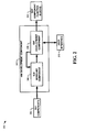
- FIG. 1 is a block diagram of an HMI development system in accordance with an aspect of an embodiment.
- a component is intended to refer to a computer-related entity, either hardware, a combination of hardware and software, software, or software in execution.
- a component may be, but is not limited to being, a process running on a processor, a processor, an object, an executable, a thread of execution, a program, and / or a computer.
- an application running on a server and the server can be a computer component.
- One or more components may reside within a process and / or thread of execution and a component may be localized on one computer and / or distributed between two or more computers.
- the subject matter may be implemented as a method, apparatus, or article of manufacture using standard programming and / or engineering techniques to produce software, firmware, hardware, or any combination thereof.
- article of manufacture (or alternatively, “computer program product”) as used herein is intended to encompass a computer program accessible from any computer-readable device, carrier, or media.
- industrial companies In order to keep pace with an ever-changing market, industrial companies continually alter their production processes. Therefore, to produce innovative products, automation system designers must be able to provide process controls and monitoring modifications at an even faster pace.
- Embodiments of HMI development systems provided herein aide automation system designers in constructing graphical user interfaces (GUIs) for controlling and/or monitoring automation activities and systems.
- GUIs graphical user interfaces
- Current methods are burdensome and require extensive re-writing of software code to build GUIs.
- the instances disclosed herein allow for the system designers to quickly and easily construct simple and/or complex user interfaces for process control/monitoring.
- the instances utilize extensible engineering platforms to provide generic applications that can then be applied to GUI development.
- Existing GUI components can also be easily imported and even employed to construct additional, more complex GUIs.
- the GUI components themselves are represented with function blocks that help to reduce the learning curve when employing these instances.
- Function block networks representative of multiple GUI components can also be automatically generated to aid the system designer.
- FIG. 1 a block diagram of an HMI development system 100 in accordance with an aspect of an embodiment is shown.
- the HMI development system 100 is comprised of an HMI development component 102 that receives GUI components 104 and provides GUI component function blocks 106.
- the HMI development component 102 also interfaces directly and/or indirectly with user interface 108 to facilitate in the HMI development.
- the function block is a well established concept in industrial systems.
- a function block is generally described as a functional unit of software with a defined interface.
- a function block is a software module that treats the encapsulated behavior in a way similar to an electronic circuit. Its functionality is easily understood by users without requiring expertise in software.
- Function blocks can also be combined to form more complex composite function blocks, while maintaining a simplistic interface like a single function block.
- the HMI development system 100 transforms the GUI components 104 into GUI component function blocks 106.
- the GUI components 104 can include, but are not limited to, GUI elements such as buttons, sliders, tanks, and/or other graphics and the like that are utilized in an HMI.
- the GUI component function blocks 106 represent single GUI component function blocks and/or composite GUI component function blocks and the like.
- the HMI development component 102 interacts with the user interface 108 to allow a user to development GUIs as needed. For example, a user can easily design a new HMI by selecting desired GUI component function blocks created from the GUI components 104, and the HMI development component 102 can then automatically link the individual and/or composite GUI component function blocks into a desired GUI component function block or function block network.
- instances of the HMI development system 100 substantially reduce the quantity of control software, substantially improve the quality of controls systems, provide more consistent module behavior, and substantially reduce development time for control systems. Additionally, because the HMI development component 102 can also be utilized to import existing GUI components, it 102 can be compatible with GUI components from other GUI development programs. This allows pre-existing GUI components to be employed by the HMI development system 100 without expensive code re-writing, drastically reducing implementation costs.
- the HMI development system 100 is typically utilized with an engineering support system (ESS) or engineering platform.
- Engineering platforms allow system designers to construct distributed measurement and control systems. By conforming the engineering platform to a common standard for the whole development process, compatibility with individual processes can be assured.
- the IEC establishes industry standards, such as, for example, the IEC 61499 standard, to facilitate in establishing industry wide conformity.
- the IEC 61499 standard is an example of a standardized architecture based on function blocks and is compatible with instances of the HMI development system 100.
- the HMI development system 100 utilizes extensible engineering platforms, like, for example, IEC 61499 compatible engineering platforms, to allow for easy integration with other development tools and to provide access to basic functions. These basic functions can include, but are not limited to, presentation functions (user interfaces), file handling, exploration, actions, and/or information processing (data handling) and the like. Extensible engineering platforms typically provide application programming interfaces (API) that allow for customized plug-in modules to be added to further enhance its capabilities (e . g ., editing, debugging, GUI development, etc.). This allows an instance of the HMI development system 100 to be easily and quickly incorporated into extensible engineering platforms.
- API application programming interfaces
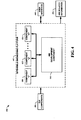
- FIG. 2 another block diagram of an HMI development system 200 in accordance with an aspect of an embodiment is depicted.
- the HMI development system 200 is comprised of an HMI development component 202 that receives GUI components 204 and provides GUI component function blocks 206.
- the HMI development component 202 is comprised of a GUI modeling component 208 and a GUI development component 210 that interfaces directly and/or indirectly with a user interface 212.
- the GUI modeling component 208 receives the GUI components 204 and automatically generates GUI function blocks and function block networks as required.
- the GUI development component 210 receives the GUI function block networks and provides for interactive HMI development via user interface 212.
- the GUI components 204 can be comprised of GUI elements obtained from various existing sources.
- the GUI modeling component 208 then creates GUI function blocks and networks for these GUI components 204.
- the GUI development component 210 then provides access to the GUI function block networks to a user via the user interface 212.
- the GUI development component 210 presents an HMI based on the GUI component function block network to the user in a visual WYSIWYG (what-you-see-is-what-you-get) fashion. The user can select, combine, modify, and/or delete aspects of the GUI function blocks to achieve a desired GUI for an automation process.
- the user can develop an HMI by, for example, dragging GUI components from a selection palette and arranging them in a visual environment provided by the GUI development component 210 via the user interface 212. This allows a visual preview of the designed HMI. By selecting adequate layouts (e.g., grid and flow layouts), a user can define how the GUI components are arranged.
- adequate layouts e.g., grid and flow layouts
- the GUI development component 210 then outputs the desired GUI elements as GUI component function blocks 206.
- the GUI component function blocks 206 can then be combined with control/monitor functionality and utilized to control and/or monitor automation processes.
- Validation components (not shown) can also be employed with the GUI development component 210 and/or stand-alone to simulate process parameters to allow users to test various GUIs based on the GUI component function blocks 206.
- the GUI development component 210 can also utilize the GUI modeling component 208 to rebuild new function block networks during the development process (e.g., when a user adds or deletes GUI components during development).
- the GUI component function blocks 206 can include, but are not limited to, XML (extensible markup language) encoded files that contain, for example, IEC 61499 compliant basic and composite function blocks, devices, and/or resource and/or system descriptions/configurations for utilization in other compliant engineering tools.
- XML extensible markup language
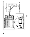
- the HMI development system 300 is comprised of an HMI development component 302 that receives GUI components 304 and provides GUI component function blocks 306.
- the HMI development component 302 is comprised of an import mechanism 308, a GUI modeling component 310, a GUI development component 312 that interfaces directly and/or indirectly with a user interface 322, a GUI function block (FB) generation component 314, a composite GUI generation component 316, and a description component 318 that provides descriptions 320.
- the GUI components 304 can include function block compatible components and/or other components not formatted for utilization with an extensible engineering platform and the like.
- the GUI components 304 can also include, but are not limited to, basic GUI components, composite GUI components, and/or logical GUI components and the like.
- the import mechanism 308 receives the GUI components 304 and encapsulates/formats them as required for utilization within an extensible engineering platform and/or other systems. This is typically accomplished with self-contained, re-usable component software such as, for example, variants of Sun Microsystem's JavaTM and JavaBeansTM and the like. In some instances, the import mechanism 308 can automatically parse a GUI component to provide elements of a required format.
- the GUI modeling component 310 can receive the imported GUI components directly from the import mechanism 308 and then employ the GUI function block (FB) generation component 314 and/or the GUI function block (FB) generation component 314 can receive the imported GUI components and transform them into function blocks before sending them to the GUI modeling component 310 for generation into GUI function block networks.
- the GUI development component 312 provides a visual representation of an HMI based on the GUI function block networks to a user via the user interface 322. A user can add, delete, and modify the GUI components as required.
- the GUI development component 312 can then employ the composite GUI generation component 316 to generate composite GUIs as required based on selections from the user.
- the GUI development component 312 can then provide the GUI component function blocks 306 to be further utilized in an extensible engineering platform.
- GUIs or descriptions of devices, resources and/or systems are generated by the description component 318 based on the HMI developed by the GUI development component 312 and are output as the descriptions 320.
- GUI component function blocks 306 can represent HMI related information such as, for example, GUIs and/or descriptions and the like. It is understood that although various components are illustrated as separate elements, some instances can incorporate some or all of the functionality of individual components into a single component. Likewise, not all of the components are necessary for every instance. For example, the import mechanism 308 might not be required if the GUI components 304 are already encapsulated in a format compatible with the extensible engineering platform.
- GUI modeling component 310 can also provide the functionality of the import mechanism 308 and/or the GUI function block (FB) generation component 314 and the like.
- GUI development component 312 can also provide the functionality of the composite GUI generation component 316 and/or the description component 318 and the like.
- the extensible engineering environment 400 includes an extensible engineering platform 402 that interfaces with the HMI development component 404.
- the extensible engineering platform 402 includes components "1-P" 410-414, where "P" represents an integer from one to infinity.
- the components "1-P” 410-414 represent applications within the extensible engineering platform 402 with which the HMI development component 404 can interface.
- the interfacing is generally accomplished through application programming interfaces (APIs).
- APIs application programming interfaces
- the components "1-P" 410-414 can include, but are not limited to, APIs for data objects, nodes, cookies, file systems, data systems, actions, and/or editors and the like.
- GUI components 406 can be received by the HMI development component 404 directly and/or indirectly via the extensible engineering platform 402 through one or more of the components "1-P" 410-414.
- GUI component related information such as HMI related information 416 can be directly obtained from the HMI development component 404 and/or obtained via one or more components "1-P" 410-414.
- the user interface 408 can interact directly with the HMI development component 404 and/or indirectly via one or more components "1-P" 410-414.
- the HMI development component 404 can provide GUI development capabilities without requiring extensive incorporation of applications already provided by the extensible engineering platform 402. This saves programming code and also substantially reduces the learning curve.
- the HMI development component 404 can be constructed as a direct plug-in module for the extensible engineering platform 402. This allows the HMI development component 404 to substantially enhance the capabilities of the extensible engineering platform in HMI development while requiring minimal integration effort.
- FIG. 5 an illustration 500 of an HMI development component 504 and typical process flow in accordance with an aspect of an embodiment is depicted.
- An input 502 is processed and made available to the HMI development component 504.
- the input 502 processing illustrated employs an example process utilizing JavaBeanTM encapsulation discussed infra and illustrated in FIG. 10.
- a user can view a visual representation of the HMI development component 504 and build an HMI through an interactive process discussed supra.
- the HMI development component 504 then provides outputs 506.
- the outputs 506 can include, but are not limited to, device, system and/or resource descriptions and composite GUI function blocks and the like including basic GUI function blocks.
- FIG. 6 a block diagram of an automation system 600 in accordance with an aspect of an embodiment is shown.
- the automation system 600 is comprised of one or more automation device(s) 602 (AUTOMATION DEVICE through AUTOMATION DEVICE N , where N is an integer from one to infinity), data storage 604 and interface 606.
- Automation device(s) 602 can include any one of a plurality of industrial, commercial and/or entertainment processes and machines such as programmable logic controllers (PLCs), pumps providing fluid transport and other processes, fans, conveyor systems, compressors, gear boxes, motion control and detection devices, sensors, screw pumps, and mixers, as well as hydraulic and pneumatic machines driven by motors.
- PLCs programmable logic controllers
- Such motors can be combined with other components, such as valves, pumps, furnaces, heaters, chillers, conveyor rollers, fans, compressors, gearboxes, and the like, as well as with appropriate motor drives to form industrial machines and actuators.
- an electric motor could be combined with a motor drive providing variable electrical power to the motor, as well as with a pump, whereby the motor rotates the pump shaft to create a controllable pumping system.
- Data storage 604 provides a storage location for housing data relating to automation device(s) 602 including but not limited to device description, location, and mechanical condition, energy or fuel consumption, completed cycles, horsepower, average RPM, efficiency rating, as well as data from sensors regarding device health and / or performance.
- the data storage 604 can be integrated or federated and linked by a communication system.
- Interface 606 is operable to connect users with a network of automation devices 602 and / or data storage 604 via a wire (e . g ., twisted pair, coaxial cable, optical fiber, Ethernet, USB (Universal Serial Bus), FireWire) or wirelessly ( e . g ., using IEEE 802.11a and / or IEEE 802.11b standards, Bluetooth technology, satellite).
- Interface 606 facilitates monitoring, extracting, transmitting, and otherwise interacting with automated device(s) 602 and associated data.
- a user such as, for example, a device operator can connect to data storage 604 and automation devices 602 over a local area network (LAN) utilizing a variety of LAN technologies, including Fiber Distributed Data Interface (FDDI), Copper Distributed Data Interface (CDDI), Ethernet/IEEE 802.3, Token Ring/IEEE 802.5, physical connection topologies such as bus, tree, ring, and star, and the like.
- FDDI Fiber Distributed Data Interface
- CDDI Copper Distributed Data Interface
- Ethernet/IEEE 802.3 Ethernet/IEEE 802.3
- Token Ring/IEEE 802.5 physical connection topologies such as bus, tree, ring, and star, and the like.
- communications between networked devices such as automation devices 602, data storage 604, and interface 606 need not be limited to those devices connected locally to a network. Local networked devices can also communicate to and from remote devices.
- FIG. 7 another block diagram of an automation system 700 in accordance with an aspect of an embodiment is depicted.
- FIG. 7 is substantially the same as system 600 except that a user employs interface 706 to interact with automation devices 702 and data storage 704 remotely over a wide area network (WAN) 708.
- WANs 708 are communication networks that span a large geographic area (e.g., nationwide, worldwide) and generally consist of the several interconnected local area networks (LANs) and metropolitan area networks (MANs).
- LANs local area networks
- MANs metropolitan area networks
- the largest WAN 708 in existence today is the Internet.
- WAN technologies include, but are not limited to, point-to-point links, circuit switching networks like Integrated Services Digital Networks (ISDN) and variations thereon, packet switching networks, T1 networks, and Digital Subscriber Lines (DSL).
- ISDN Integrated Services Digital Networks
- DSL Digital Subscriber Lines
- the embodiments may be described in the general context of computer-executable instructions, such as program modules, executed by one or more components.
- program modules include routines, programs, objects, data structures, etc., that perform particular tasks or implement particular abstract data types.
- functionality of the program modules may be combined or distributed as desired in various instances of the embodiments.
- GUI components can include, but are not limited to, basic GUI components, composite GUI components, and/or logical GUI components such as device, resource and/or system descriptions and the like.
- GUI function block networks are then automatically generated from the GUI components 806. This can include generating GUI function blocks that are then linked to form the GUI function block network.
- a user interactive interface is then provided in an extensible engineering platform to allow HMI development via utilization of the GUI function block network 808, ending the flow 810. Utilization within the extensible engineering platform allows for encapsulation of GUI components in a common format that easily conforms to the extensible engineering platform, allowing existing GUI elements to be readily imported. Users can easily manipulate the GUI function block networks to create desired HMIs.
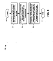
- FIG. 9 a flow diagram of a method 900 of importing GUI components for HMI development in accordance with an aspect of an embodiment is depicted.
- the method 900 starts 902 by obtaining GUI components associated with at least one automation system 904.
- the GUI component is then parsed to provide elements of a required format for an extensible engineering platform 906.
- the GUI elements are then encapsulated within self-contained, reusable component software that is compatible with the extensible engineering platform 908, ending the flow 910. This substantially improves the importing of existing GUI function blocks.
- FIG. 9 is a flow diagram of a method 900 of importing GUI components for HMI development in accordance with an aspect of an embodiment.
- the method 900 starts 902 by obtaining GUI components associated with at least one automation system 904.
- the GUI component is then parsed to provide elements of a required format for an extensible engineering platform 906.
- the GUI elements are then encapsulated within self-contained, reusable component software that is compatible with the extensible engineering platform 908, ending the flow 910.
- FIG. 10 illustrates a flow 1000 where a JavaBeanTM based method can be employed on a GUI component 1002 to parse an IEC 61499 XML file 1008 by a JavaBeanTM generator 1004 and, based on this file, generate a JavaBeanTM including a BeanInfo class 1010.
- Configuration parameters can then be detected utilizing a mechanism that looks for all data inputs that are bonded with the event-input INIT.
- This configuration interface is extended with code for instantiating and executing the IEC 61499 GUI component. This code is independent of the IEC 61499 GUI component and can be incorporated into the JavaBeanTM mechanism in text form.
- the JavaBeanTM is representative of a self-contained component that can be utilized in a specific tool integration platform.
- the BeanInfo class is representative of a type of interface and instantiation support.
- FIG. 11 and the following discussion is intended to provide a brief, general description of a suitable computing environment 1100 in which the various aspects of the embodiments can be implemented. While the embodiments have been described above in the general context of computer-executable instructions of a computer program that runs on a local computer and / or remote computer, those skilled in the art will recognize that the embodiments can also be implemented in combination with other program modules. Generally, program modules include routines, programs, components, data structures, etc., that perform particular tasks and / or implement particular abstract data types.
- inventive methods can be practiced with other computer system configurations, including single-processor or multi-processor computer systems, minicomputers, mainframe computers, as well as personal computers, handheld computing devices, microprocessor-based and / or programmable consumer electronics, and the like, each of which can operatively communicate with one or more associated devices.
- the illustrated aspects of the embodiments can also be practiced in distributed computing environments where certain tasks are performed by remote processing devices that are linked through a communications network. However, some, if not all, aspects of the embodiments can be practiced on stand-alone computers.
- program modules can be located in local and / or remote memory storage devices.
- a component is intended to refer to a computer-related entity, either hardware, a combination of hardware and software, software, or software in execution.
- a component can be, but is not limited to, a process running on a processor, a processor, an object, an executable, a thread of execution, a program, and a computer.
- an application running on a server and / or the server can be a component.
- a component can include one or more subcomponents.
- an exemplary environment 1110 for implementing various aspects of the invention includes a computer 1112.
- the computer 1112 includes a processing unit 1114, a system memory 1116, and a system bus 1118.
- the system bus 1118 couples system components including, but not limited to, the system memory 1116 to the processing unit 1114.
- the processing unit 1114 can be any of various available processors. Dual microprocessors and other multiprocessor architectures also can be employed as the processing unit 1114.
- the system bus 1118 can be any of several types of bus structure(s) including the memory bus or memory controller, a peripheral bus or external bus, and/or a local bus using any variety of available bus architectures including, but not limited to, 11-bit bus, Industrial Standard Architecture (ISA), Micro-Channel Architecture (MSA), Extended ISA (EISA), Intelligent Drive Electronics (IDE), VESA Local Bus (VLB), Peripheral Component Interconnect (PCI), Universal Serial Bus (USB), Advanced Graphics Port (AGP), Personal Computer Memory Card International Association bus (PCMCIA), and Small Computer Systems Interface (SCSI).
- ISA Industrial Standard Architecture
- MSA Micro-Channel Architecture
- EISA Extended ISA
- IDE Intelligent Drive Electronics
- VLB VESA Local Bus
- PCI Peripheral Component Interconnect
- USB Universal Serial Bus
- AGP Advanced Graphics Port
- PCMCIA Personal Computer Memory Card International Association bus
- SCSI Small Computer Systems Interface
- the system memory 1116 includes volatile memory 1120 and nonvolatile memory 1122.
- the basic input/output system (BIOS) containing the basic routines to transfer information between elements within the computer 1112, such as during start-up, is stored in nonvolatile memory 1122.
- nonvolatile memory 1122 can include read only memory (ROM), programmable ROM (PROM), electrically programmable ROM (EPROM), electrically erasable ROM (EEPROM), or flash memory.
- Volatile memory 1120 includes random access memory (RAM), which acts as external cache memory.
- RAM is available in many forms such as synchronous RAM (SRAM), dynamic RAM (DRAM), synchronous DRAM (SDRAM), double data rate SDRAM (DDR SDRAM), enhanced SDRAM (ESDRAM), Synchlink DRAM (SLDRAM), and direct Rambus RAM (DRRAM).
- SRAM synchronous RAM
- DRAM dynamic RAM
- SDRAM synchronous DRAM
- DDR SDRAM double data rate SDRAM
- ESDRAM enhanced SDRAM
- SLDRAM Synchlink DRAM
- DRRAM direct Rambus RAM
- Computer 1112 also includes removable/non-removable, volatile/non-volatile computer storage media.
- Fig. 11 illustrates, for example, disk storage 1124.
- Disk storage 1124 includes, but is not limited to, devices like a magnetic disk drive, floppy disk drive, tape drive, Jaz drive, Zip drive, LS-100 drive, flash memory card, or memory stick.
- disk storage 1124 can include storage media separately or in combination with other storage media including, but not limited to, an optical disk drive such as a compact disk ROM device (CD-ROM), CD recordable drive (CD-R Drive), CD rewritable drive (CD-RW Drive) or a digital versatile disk ROM drive (DVD-ROM).
- CD-ROM compact disk ROM device
- CD-R Drive CD recordable drive
- CD-RW Drive CD rewritable drive
- DVD-ROM digital versatile disk ROM drive
- a removable or non-removable interface is typically used such as interface 1126.
- Fig 11 describes software that acts as an intermediary between users and the basic computer resources described in suitable operating environment 1110.
- Such software includes an operating system 1128.
- Operating system 1128 which can be stored on disk storage 1124, acts to control and allocate resources of the computer system 1112.
- System applications 1130 take advantage of the management of resources by operating system 1128 through program modules 1132 and program data 1134 stored either in system memory 1116 or on disk storage 1124. It is to be appreciated that the present invention can be implemented with various operating systems or combinations of operating systems.
- Input devices 1136 include, but are not limited to, a pointing device such as a mouse, trackball, stylus, touch pad, keyboard, microphone, joystick, game pad, satellite dish, scanner, TV tuner card, digital camera, digital video camera, web camera, and the like. These and other input devices connect to the processing unit 1114 through the system bus 1118 via interface port(s) 1138.
- Interface port(s) 1138 include, for example, a serial port, a parallel port, a game port, and a universal serial bus (USB).
- Output device(s) 1140 use some of the same type of ports as input device(s) 1136.
- a USB port may be used to provide input to computer 1112 and to output information from computer 1112 to an output device 1140.
- Output adapter 1142 is provided to illustrate that there are some output devices 1140 like monitors, speakers, and printers, among other output devices 1140 that require special adapters.
- the output adapters 1142 include, by way of illustration and not limitation, video and sound cards that provide a means of connection between the output device 1140 and the system bus 1118. It should be noted that other devices and/or systems of devices provide both input and output capabilities such as remote computer(s) 1144.
- Computer 1112 can operate in a networked environment using logical connections to one or more remote computers, such as remote computer(s) 1144.
- the remote computer(s) 1144 can be a personal computer, a server, a router, a network PC, a workstation, a microprocessor based appliance, a peer device or other common network node and the like, and typically includes many or all of the elements described relative to computer 1112. For purposes of brevity, only a memory storage device 1146 is illustrated with remote computer(s) 1144.
- Remote computer(s) 1144 is logically connected to computer 1112 through a network interface 1148 and then physically connected via communication connection 1150.
- Network interface 1148 encompasses communication networks such as local-area networks (LAN) and widearea networks (WAN).
- LAN technologies include Fiber Distributed Data Interface (FDDI), Copper Distributed Data Interface (CDDI), Ethernet/IEEE 802.3, Token Ring/IEEE 802.5 and the like.
- WAN technologies include, but are not limited to, point-to-point links, circuit switching networks like Integrated Services Digital Networks (ISDN) and variations thereon, packet switching networks, and Digital Subscriber Lines (DSL).
- ISDN Integrated Services Digital Networks
- DSL Digital Subscriber Lines
- Communication connection(s) 1150 refers to the hardware/software employed to connect the network interface 1148 to the bus 1118. While communication connection 1150 is shown for illustrative clarity inside computer 1112, it can also be external to computer 1112.
- the hardware/software necessary for connection to the network interface 1148 includes, for exemplary purposes only, internal and external technologies such as, modems including regular telephone grade modems, cable modems and DSL modems, ISDN adapters, and Ethernet cards.
- FIG. 12 is another block diagram of a sample computing environment 1200 with which embodiments can interact.
- the system 1200 further illustrates a system that includes one or more client(s) 1202.
- the client(s) 1202 can be hardware and / or software ( e . g ., threads, processes, computing devices).
- the system 1200 also includes one or more server(s) 1204.
- the server(s) 1204 can also be hardware and / or software ( e . g ., threads, processes, computing devices).
- One possible communication between a client 1202 and a server 1204 can be in the form of a data packet adapted to be transmitted between two or more computer processes.
- the system 1200 includes a communication framework 1208 that can be employed to facilitate communications between the client(s) 1202 and the server(s) 1204.
- the client(s) 1202 are connected to one or more client data store(s) 1210 that can be employed to store information local to the client(s) 1202.
- the server(s) 1204 are connected to one or more server data store(s) 1206 that can be employed to store information local to the server(s) 1204.
- a data packet transmitted between two or more computer components that facilitates control of automation systems is comprised of, at least in part, information relating to a GUI component that is represented by, at least in part, a function block compatible with automation development systems.
- systems and / or methods of the embodiments can be utilized in automation GUI development facilitating computer components and non-computer related components alike. Further, those skilled in the art will recognize that the systems and / or methods of the embodiments are employable in a vast array of electronic related technologies, including, but not limited to, computers, servers and / or handheld electronic devices, and the like.
- GUI framework leverages interfaces of extensible engineering platforms to provide a tool that easily constructs HMIs for automation systems.
- the GUI framework can import existing GUI components and/or create new GUI components.
- the GUI framework can also combine basic GUI components to create complex composite GUI components.
- An import mechanism can also be employed to import existing GUI components by encapsulating them in common, reusable software code that is compatible with an extensible engineering platform.
- the GUI framework utilizes function blocks to represent the GUI components and automatically generates GUI function block networks with linking as required. This allows complex GUIs to be created with minimal user effort.
Applications Claiming Priority (1)
| Application Number | Priority Date | Filing Date | Title |
|---|---|---|---|
| US42742306A | 2006-06-29 | 2006-06-29 |
Publications (2)
| Publication Number | Publication Date |
|---|---|
| EP1873634A2 true EP1873634A2 (de) | 2008-01-02 |
| EP1873634A3 EP1873634A3 (de) | 2013-10-09 |
Family
ID=38603389
Family Applications (1)
| Application Number | Title | Priority Date | Filing Date |
|---|---|---|---|
| EP07012541.4A Withdrawn EP1873634A3 (de) | 2006-06-29 | 2007-06-26 | HMI-Rahmen für Engineering-Plattformen erweiterbarer Automatisierungssysteme |
Country Status (3)
| Country | Link |
|---|---|
| US (1) | US20110093800A1 (de) |
| EP (1) | EP1873634A3 (de) |
| CN (1) | CN101110029B (de) |
Cited By (4)
| Publication number | Priority date | Publication date | Assignee | Title |
|---|---|---|---|---|
| EP2482207A3 (de) * | 2011-02-01 | 2016-10-26 | Rockwell Automation Technologies, Inc. | Durchsuchbarer Katalog für EDGE-Definitionen |
| EP3223146A1 (de) * | 2016-03-25 | 2017-09-27 | LSIS Co., Ltd. | Hmi-system |
| WO2018058451A1 (zh) * | 2016-09-29 | 2018-04-05 | 西门子公司 | 一种人机界面生成方法、组件以及电子设备 |
| WO2019115553A3 (de) * | 2017-12-11 | 2019-09-19 | Qass Gmbh | Verfahren und messvorrichtungen zum erkennen von ereignissen in einem materialbearbeitungs- oder -herstellungsprozess unter verwendung von ereignismustern |
Families Citing this family (14)
| Publication number | Priority date | Publication date | Assignee | Title |
|---|---|---|---|---|
| JP4875043B2 (ja) * | 2008-10-31 | 2012-02-15 | 株式会社東芝 | フレームワークプログラム及びクライアント装置 |
| US20110022978A1 (en) * | 2009-07-23 | 2011-01-27 | Rockwell Automation Technologies, Inc. | Intelligent device framework |
| US9098294B2 (en) * | 2010-12-31 | 2015-08-04 | Verizon Patent And Licensing Inc. | Building block based graphical user interface design and development systems and methods |
| US8938685B2 (en) * | 2010-12-31 | 2015-01-20 | Verizon Patent And Licensing Inc. | Automated graphical user interface design and development systems and methods |
| CN103792857A (zh) * | 2012-10-31 | 2014-05-14 | 洛克威尔自动控制技术股份有限公司 | 可扩展的自动化系统 |
| US8799858B2 (en) | 2012-12-14 | 2014-08-05 | Siemens Aktiengesellschaft | Efficient execution of human machine interface applications in a heterogeneous multiprocessor environment |
| US9311062B2 (en) | 2013-10-31 | 2016-04-12 | International Business Machines Corporation | Consolidating and reusing portal information |
| US9665272B2 (en) * | 2014-02-28 | 2017-05-30 | Invensys Systems, Inc. | Touch gesture for connection of streams in a flowsheet simulator |
| JP6068758B2 (ja) * | 2014-06-26 | 2017-01-25 | 株式会社デジタル | プログラマブル表示器 |
| EP3015934B1 (de) * | 2014-10-30 | 2018-11-28 | Siemens Aktiengesellschaft | Verfahren zum Vorschlagen einer Vielzahl von Bildschirmen, Verfahren und System zum Speichern eines oder mehrerer Bildschirme |
| WO2018058304A1 (zh) * | 2016-09-27 | 2018-04-05 | 西门子公司 | 自动生成用户界面的工业控制器及方法 |
| US10983511B2 (en) | 2017-02-14 | 2021-04-20 | Quest Automated Services, LLC | Automation control system |
| CN106933212B (zh) * | 2017-04-21 | 2019-12-10 | 华南理工大学 | 一种分布式制造环境下的可重构工业机器人编程控制方法 |
| US20180356805A1 (en) * | 2017-06-07 | 2018-12-13 | Honeywell Limited | Data Source Agnostic Browser-Based Monitoring Display for Monitoring Manufacturing or Control Process |
Family Cites Families (29)
| Publication number | Priority date | Publication date | Assignee | Title |
|---|---|---|---|---|
| US6282454B1 (en) * | 1997-09-10 | 2001-08-28 | Schneider Automation Inc. | Web interface to a programmable controller |
| US20020152289A1 (en) * | 1997-09-10 | 2002-10-17 | Schneider Automation Inc. | System and method for accessing devices in a factory automation network |
| US7035898B1 (en) * | 1997-09-10 | 2006-04-25 | Schneider Automation Inc. | System for programming a factory automation device using a web browser |
| US6201996B1 (en) * | 1998-05-29 | 2001-03-13 | Control Technology Corporationa | Object-oriented programmable industrial controller with distributed interface architecture |
| JP2000047857A (ja) * | 1998-07-27 | 2000-02-18 | Yamatake Corp | イベント駆動型ファンクションブロックのプログラミング方法とプログラム記録媒体 |
| US6401230B1 (en) * | 1998-12-04 | 2002-06-04 | Altera Corporation | Method of generating customized megafunctions |
| US7017116B2 (en) * | 1999-01-06 | 2006-03-21 | Iconics, Inc. | Graphical human-machine interface on a portable device |
| US6718533B1 (en) * | 1999-02-26 | 2004-04-06 | Real-Time Innovations, Inc. | Method for building a real-time control system with mode and logical rate |
| US6477435B1 (en) * | 1999-09-24 | 2002-11-05 | Rockwell Software Inc. | Automated programming system for industrial control using area-model |
| JP2001282655A (ja) * | 2000-03-28 | 2001-10-12 | Canon Inc | ネットワークデバイス管理方法、装置、および記憶媒体 |
| AUPQ808700A0 (en) * | 2000-06-09 | 2000-07-06 | Honeywell Limited | Human-machine interface |
| US7174534B2 (en) * | 2001-01-22 | 2007-02-06 | Symbol Technologies, Inc. | Efficient system and method for running and analyzing multi-channel, multi-modal applications |
| US8218555B2 (en) * | 2001-04-24 | 2012-07-10 | Nvidia Corporation | Gigabit ethernet adapter |
| US7290030B2 (en) * | 2001-07-13 | 2007-10-30 | Rockwell Automation Technologies, Inc. | Internet object based interface for industrial controller |
| US20030105535A1 (en) * | 2001-11-05 | 2003-06-05 | Roman Rammler | Unit controller with integral full-featured human-machine interface |
| US7054922B2 (en) * | 2001-11-14 | 2006-05-30 | Invensys Systems, Inc. | Remote fieldbus messaging via Internet applet/servlet pairs |
| KR100475432B1 (ko) * | 2002-02-26 | 2005-03-10 | 삼성전자주식회사 | 그래픽 사용자 인터페이스의 디자인 변경 방법 및 이를 위한 기록매체 |
| AU2003223746A1 (en) * | 2002-04-25 | 2003-11-10 | Arc International | Apparatus and method for managing integrated circuit designs |
| US7165226B2 (en) * | 2002-08-23 | 2007-01-16 | Siemens Aktiengesellschaft | Multiple coupled browsers for an industrial workbench |
| US7181515B2 (en) * | 2003-01-24 | 2007-02-20 | Industrial Technology Research Institute | Method of accessing distributed field equipments by a host through a plurality of intelligent network gateways |
| US20040210664A1 (en) * | 2003-04-17 | 2004-10-21 | Schneider Automation Inc. | System and method for transmitting data |
| US20050043620A1 (en) * | 2003-08-20 | 2005-02-24 | Siemens Medical Solutions Usa, Inc. | Diagnostic medical ultrasound system communication network architecture and method |
| US7324856B1 (en) * | 2003-09-25 | 2008-01-29 | Rockwell Automation Technologies, Inc. | Autogeneration of code via human-machine interfaces (HMI) and self-building HMI |
| US20050155043A1 (en) * | 2004-01-08 | 2005-07-14 | Schulz Kurt S. | Human-machine interface system and method for remotely monitoring and controlling a machine |
| JP2007536634A (ja) * | 2004-05-04 | 2007-12-13 | フィッシャー−ローズマウント・システムズ・インコーポレーテッド | プロセス制御システムのためのサービス指向型アーキテクチャ |
| EP1674954A1 (de) * | 2004-12-21 | 2006-06-28 | Siemens Aktiengesellschaft | System und Verfahren zur Wiederverwendung von Projektierungsdaten |
| US7418305B2 (en) * | 2005-02-09 | 2008-08-26 | Siemens Corporate Research, Inc. | Method of generating a component of a component-based automation system |
| US7706895B2 (en) * | 2005-02-25 | 2010-04-27 | Rockwell Automation Technologies, Inc. | Reliable messaging instruction |
| US20080080543A1 (en) * | 2006-09-28 | 2008-04-03 | Rockwell Automation Technologies, Inc. | Network switch with controller i/o capability |
-
2007
- 2007-06-26 EP EP07012541.4A patent/EP1873634A3/de not_active Withdrawn
- 2007-06-29 CN CN2007101290393A patent/CN101110029B/zh not_active Expired - Fee Related
-
2010
- 2010-12-23 US US12/977,259 patent/US20110093800A1/en not_active Abandoned
Non-Patent Citations (4)
| Title |
|---|
| CHRISTENSEN J.H. ET AL.: "IEEE Transactions on Industrial Informatics", vol. 1, 1 February 2005, IEEE SERVICE CENTER, article "OOONEIDA: An Open, Object-Oriented Knowledge Economy for Intelligent Industrial Automation", pages: 4 - 17 |
| HUMMER O. ET AL.: "Development of an Extensible Engineering Support Tool for IEC 61499 Considering WYSIWYG GUI Building as Example", 10TH IEEE INTERNATIONAL CONFERENCE ON EMERGING TECHNOLOGIES AND FACTORY AUTOMATION, vol. 2, 19 September 2005 (2005-09-19), pages 607 - 613 |
| SCHWAB C. ET AL.: "The Modular TORERO IEC 61499 Engineering Platform - Eclipse in Automation", 10TH IEEE INTERNATIONAL CONFERENCE ON EMERGING TECHNOLOGIES AND FACTORY AUTOMATION, vol. 2, 19 September 2005 (2005-09-19), pages 265 - 272 |
| XIUJUN CAI ET AL.: "Design and Implementation of a Prototype Control System According to IEC 61499", EMERGING TECHNOLOGIES AND FACTORY AUTOMATION, 2003, PROCEEDINGS, EFTA '03, vol. 2, 16 September 2003 (2003-09-16), pages 269 - 276 |
Cited By (8)
| Publication number | Priority date | Publication date | Assignee | Title |
|---|---|---|---|---|
| EP2482207A3 (de) * | 2011-02-01 | 2016-10-26 | Rockwell Automation Technologies, Inc. | Durchsuchbarer Katalog für EDGE-Definitionen |
| EP3223146A1 (de) * | 2016-03-25 | 2017-09-27 | LSIS Co., Ltd. | Hmi-system |
| CN107229462A (zh) * | 2016-03-25 | 2017-10-03 | Ls 产电株式会社 | Hmi系统 |
| CN107229462B (zh) * | 2016-03-25 | 2021-04-02 | Ls 产电株式会社 | Hmi系统 |
| WO2018058451A1 (zh) * | 2016-09-29 | 2018-04-05 | 西门子公司 | 一种人机界面生成方法、组件以及电子设备 |
| US11513508B2 (en) | 2016-09-29 | 2022-11-29 | Siemens Aktiengesellschaft | Method, component, and electronic device for creating human machine interface |
| WO2019115553A3 (de) * | 2017-12-11 | 2019-09-19 | Qass Gmbh | Verfahren und messvorrichtungen zum erkennen von ereignissen in einem materialbearbeitungs- oder -herstellungsprozess unter verwendung von ereignismustern |
| US11931842B2 (en) | 2017-12-11 | 2024-03-19 | Qass Gmbh | Methods, (measuring) devices, and components thereof, for identifying events in a material-processing or material production process using event patterns |
Also Published As
| Publication number | Publication date |
|---|---|
| CN101110029A (zh) | 2008-01-23 |
| CN101110029B (zh) | 2010-06-16 |
| US20110093800A1 (en) | 2011-04-21 |
| EP1873634A3 (de) | 2013-10-09 |
Similar Documents
| Publication | Publication Date | Title |
|---|---|---|
| EP1873634A2 (de) | HMI-Rahmen für Engineering-Plattformen erweiterbarer Automatisierungssysteme | |
| US8683017B2 (en) | Web-based configuration of distributed automation systems | |
| US8028045B2 (en) | Web-based configuration server for automation systems | |
| KR101936027B1 (ko) | 엔지니어링 툴, 시스템 및 모듈 | |
| US7756966B2 (en) | Dynamic browser-based industrial automation interface system and method | |
| US20150186119A1 (en) | Industrial automation device with editor and graphical object mobile visualization | |
| Ladiges et al. | Integration of modular process units into process control systems | |
| US10606562B2 (en) | Method and system for generating PLC code with a connectivity model | |
| CN108681444A (zh) | 一种基于xml技术的软plc组态开发方法 | |
| US20200103879A1 (en) | System and Method for Implementing a User Interface to a Multi-Agent Distributed Control System | |
| US20120226786A1 (en) | System and method for porting of device software | |
| CN102521120A (zh) | 一种软件自动化测试系统及方法 | |
| JP2016197440A (ja) | スクリプトを形成する方法および装置 | |
| EP3751412A1 (de) | Computerimplementiertes verfahren zur erzeugung eines opc-ua-informationsmodells | |
| Pereira et al. | DINASORE: A Dynamic Intelligent Reconfiguration Tool for Cyber-Physical Production Systems. | |
| Gómez et al. | A model-based approach for developing event-driven architectures with asyncapi | |
| Um et al. | Development a modular factory with modular software components | |
| Fleischmann et al. | Automated generation of human-machine interfaces in electric drives manufacturing | |
| Vathoopan et al. | 31 skill-based engineering of automation systems: Use case and evaluation | |
| Siverskiy | Implementing an AAS for a Siemens motor control system | |
| Gomez | Survey of SCADA Systems and Visualization of a real life process | |
| CN115002236A (zh) | 一种数据协议可视化配置的边缘软网关 | |
| Van Der Wal | Using abstraction to reduce machine integration efforts: Save packaging machine integration time using IEC 61131-3 standard and PLCopen Motion Control Function Blocks to preserve programming value. | |
| Rahaman et al. | Testing and verifying PLC code with a virtual model of Tetra Pak filling machine | |
| Indasyah et al. | Cost-Effective Approach for Data Integration on Tire Stacking Machine Through Real-Time Industrial Machine Monitoring System |
Legal Events
| Date | Code | Title | Description |
|---|---|---|---|
| PUAI | Public reference made under article 153(3) epc to a published international application that has entered the european phase |
Free format text: ORIGINAL CODE: 0009012 |
|
| AK | Designated contracting states |
Kind code of ref document: A2 Designated state(s): AT BE BG CH CY CZ DE DK EE ES FI FR GB GR HU IE IS IT LI LT LU LV MC MT NL PL PT RO SE SI SK TR |
|
| AX | Request for extension of the european patent |
Extension state: AL BA HR MK YU |
|
| PUAL | Search report despatched |
Free format text: ORIGINAL CODE: 0009013 |
|
| AK | Designated contracting states |
Kind code of ref document: A3 Designated state(s): AT BE BG CH CY CZ DE DK EE ES FI FR GB GR HU IE IS IT LI LT LU LV MC MT NL PL PT RO SE SI SK TR |
|
| AX | Request for extension of the european patent |
Extension state: AL BA HR MK RS |
|
| RIC1 | Information provided on ipc code assigned before grant |
Ipc: G06F 9/44 20060101AFI20130902BHEP |
|
| 17P | Request for examination filed |
Effective date: 20140408 |
|
| RBV | Designated contracting states (corrected) |
Designated state(s): AT BE BG CH CY CZ DE DK EE ES FI FR GB GR HU IE IS IT LI LT LU LV MC MT NL PL PT RO SE SI SK TR |
|
| AKX | Designation fees paid |
Designated state(s): DE FR GB |
|
| STAA | Information on the status of an ep patent application or granted ep patent |
Free format text: STATUS: THE APPLICATION HAS BEEN WITHDRAWN |
|
| 18W | Application withdrawn |
Effective date: 20170324 |