EP1873432A2 - Vorrichtung zum automatischen Be- und Entlüften eines Druckfluid-Versorgungssystems - Google Patents
Vorrichtung zum automatischen Be- und Entlüften eines Druckfluid-Versorgungssystems Download PDFInfo
- Publication number
- EP1873432A2 EP1873432A2 EP07110436A EP07110436A EP1873432A2 EP 1873432 A2 EP1873432 A2 EP 1873432A2 EP 07110436 A EP07110436 A EP 07110436A EP 07110436 A EP07110436 A EP 07110436A EP 1873432 A2 EP1873432 A2 EP 1873432A2
- Authority
- EP
- European Patent Office
- Prior art keywords
- valve
- closure body
- opening
- valve housing
- supply system
- Prior art date
- Legal status (The legal status is an assumption and is not a legal conclusion. Google has not performed a legal analysis and makes no representation as to the accuracy of the status listed.)
- Granted
Links
- 239000012530 fluid Substances 0.000 title claims abstract description 16
- 238000009423 ventilation Methods 0.000 title description 4
- 238000005273 aeration Methods 0.000 title 1
- 238000013022 venting Methods 0.000 claims description 11
- 230000006835 compression Effects 0.000 claims description 3
- 238000007906 compression Methods 0.000 claims description 3
- 230000007704 transition Effects 0.000 claims description 3
- 230000000284 resting effect Effects 0.000 claims 1
- 238000002485 combustion reaction Methods 0.000 description 8
- 238000009434 installation Methods 0.000 description 5
- XLYOFNOQVPJJNP-UHFFFAOYSA-N water Substances O XLYOFNOQVPJJNP-UHFFFAOYSA-N 0.000 description 3
- 238000001816 cooling Methods 0.000 description 2
- 238000013016 damping Methods 0.000 description 2
- 230000000740 bleeding effect Effects 0.000 description 1
- 230000037396 body weight Effects 0.000 description 1
- 238000010276 construction Methods 0.000 description 1
- 230000007423 decrease Effects 0.000 description 1
Images
Classifications
-
- F—MECHANICAL ENGINEERING; LIGHTING; HEATING; WEAPONS; BLASTING
- F16—ENGINEERING ELEMENTS AND UNITS; GENERAL MEASURES FOR PRODUCING AND MAINTAINING EFFECTIVE FUNCTIONING OF MACHINES OR INSTALLATIONS; THERMAL INSULATION IN GENERAL
- F16K—VALVES; TAPS; COCKS; ACTUATING-FLOATS; DEVICES FOR VENTING OR AERATING
- F16K24/00—Devices, e.g. valves, for venting or aerating enclosures
- F16K24/04—Devices, e.g. valves, for venting or aerating enclosures for venting only
-
- F—MECHANICAL ENGINEERING; LIGHTING; HEATING; WEAPONS; BLASTING
- F16—ENGINEERING ELEMENTS AND UNITS; GENERAL MEASURES FOR PRODUCING AND MAINTAINING EFFECTIVE FUNCTIONING OF MACHINES OR INSTALLATIONS; THERMAL INSULATION IN GENERAL
- F16K—VALVES; TAPS; COCKS; ACTUATING-FLOATS; DEVICES FOR VENTING OR AERATING
- F16K24/00—Devices, e.g. valves, for venting or aerating enclosures
- F16K24/06—Devices, e.g. valves, for venting or aerating enclosures for aerating only
Definitions
- the invention relates to a device for ventilating and venting a pressurized fluid supply system, comprising an automatic valve which comprises a closing body which opens against the venting direction and actuating means which are associated with the closure body and load the same in the opening direction.
- the actuating means can be overpressed by a pressurized fluid acting on the closure body.
- Pressure fluid supply systems in particular oil-hydraulic supply systems for switching oil supply for internal combustion engines, must, to ensure proper functioning, be free of air, so completely filled with incompressible pressure fluid.
- the pressure oil of such supply systems is provided by an oil pump driven by the internal combustion engine itself.
- the pressure in the supply system decreases as a result of cooling of the oil and a concomitant reduction in the oil volume, and there is an air intake, for example, through leaks in the supply system or in the pressure oil-operated units.
- the intake air must be removed from the supply system when the internal combustion engine is restarted. This is usually done at the highest point of the supply system, where the intake air predominantly collects arranged vent valves. In order for the air drawn in by the supply system when the internal combustion engine is shut down to be located specifically in the region in which the venting valve is arranged, this is generally also designed as a venting valve which is opened manually or opens automatically.
- CH 301104 is already an automatic valve referred to in the preamble of claim 1 type for ventilation of pipelines, in which the approximately plate-like closure body is loaded by its own weight in the opening direction such that the valve is open in the pressureless state of the pipeline.
- a spring acting in the closing direction on the closure body or - in another embodiment - a counterweight is designed so that the valve adjusts to a partial stroke with pressure-free line.
- the known valve Since the closure body and acting in the closing direction of the spring or the counterweight form a vibration system, there is also the risk of vibration during operation. For this reason, the known valve is equipped with a complex hydraulic damping system for damping the closing movement, whereby this valve is structurally and structurally very expensive and has a large installation space requirement.
- the invention has for its object to provide a device for loading and bleeding a pressurized fluid supply system, which is structurally and structurally simple and allows any installation positions.
- the invention is based on the finding that self-weight-independent actuating means for opening the closure body can realize both structural simplification and the form of use, to install the valve in any desired spatial position and thus make it suitable for non-stationary operation in vehicles, for example.
- the invention is therefore based on a device for ventilating and venting a pressurized fluid supply system, with an automatic valve which comprises a closing body which opens against the venting direction and actuating means which are associated with this closure body and load the same in the opening direction, which pressure fluid acts on the closure body are suppressed.
- an automatic valve which comprises a closing body which opens against the venting direction and actuating means which are associated with this closure body and load the same in the opening direction, which pressure fluid acts on the closure body are suppressed.
- the closure body is loaded by spring means whose design spring force is greater than a force applied by an outflowing air flow to the closure body and optionally generated by a force acting in the closing direction of the closure body weight component force.
- the spring means are designed so that the valve opens at a pressure drop in the supply system and thus a targeted ventilation in the region of the valve is ensured, and during the venting phase, in which the closure body is acted upon by the air flow, initially remains open and then closes when the closure body is acted upon by the re-pressurized pressurized fluid.
- the design of the spring means is also made such that, for example, even with a vertical installation of the valve with a downward opening movement of the closure body whose weight is absorbed by the spring means, so that the above-described function of the valve is ensured even in this installation position.
- the valve according to the invention can be designed to be very simple in construction. It comprises, for example, a valve housing equipped with an inlet opening and an outlet opening, with a closure body preferably suspended therein between a closed position abutting a valve seat and an opening position raised therefrom and defined by a stop.
- valve housing has substantially the shape of a circular cylinder, on whose one end face the inlet opening and on the other end side of the outlet opening is formed.
- the circular cylinder in the venting direction has a first section of larger diameter and a second section of smaller diameter, that the closure body is movably arranged in the first section in the direction of the cylinder axis and with a transition region between the first and the second portion formed valve seat cooperates, and that the spring means comprise a helical compression spring which is arranged between the closure body and an inner wall formed on the inner wall of the second portion.
- the closure body is preferably a ball, which is guided in a guide cage arranged in the first section, wherein the opening of the valve defining stop is formed on the inner wall of the guide cage.
- a preferred installation arrangement of the valve according to the invention provides that the circular cylindrical valve housing is installed in at least approximately vertical position with upwardly facing inlet opening in a bottom wall of a pressurized fluid supply line or the like, such that the valve housing projects upwards into the line, and that the connecting lines for loads connected to the supply system, they are connected to the bottom wall of the line parallel to the valve.
- the valve forms a kind of overflow nozzle, which ensures in the container a certain, defined by the height of the inlet opening of the valve above the bottom wall of the container pressure fluid level, so that at the restart of the system from the beginning, a supply of supplied with pressurized oil units is ensured.
- a supply line 4 In a housing 2, which is part of a pressurized oil supply system for an internal combustion engine, for example, there is a supply line 4, are supplied from the supply lines to be supplied via connecting lines 6, 8, not shown units.
- the supply line 4 is provided in the region of its bottom wall 10 with a vent hole 12, in which a designated as a whole with 14 valve is inserted fluid-tight.
- the valve 14 comprises a substantially circular cylindrical valve housing 16, at the upper end side of an inlet opening 18 and at its lower side an outlet opening 20 is formed.
- the valve housing 16 has an upper, first portion 22 of larger diameter and a lower, second portion 24 of smaller diameter.
- a valve seat 26 is formed on the inner wall of the valve housing 16 in the transition from the first portion 22 to the second portion 24, a valve seat 26 is formed.
- a guide cage 28 is arranged, in which in the direction of the cylinder axis 30 of the valve freely movable, spherical closure body 32 is guided.
- the closure body 32 is movable between a closing position abutting the valve seat 26 and a lifting position lifted therefrom and defined by a stop 34 formed on the inner wall of the guide cage 28.
- the closure body 32 is held by spring means 36 in its open position in the pressureless state of the supply system or the supply line 4.
- the spring means 36 are formed in the present embodiment by a helical compression spring, which is supported on a formed on the inner wall of the second portion 24 inner collar 38.
- valve 14 The function of the valve 14 is described as follows:
- the closure body 32 In the pressureless state of the supply system or the supply line 4, the closure body 32 is held by the spring means 36 acting in the opening direction in its illustrated in the figures, abutting the stop 34 open position.
- the accumulated in the upper part of the supply line 4 air is first ejected via the input port 18, the valve housing 16 and the outlet port 20 in the direction of the arrows shown from the supply line 4 and the valve.
- the force exerted thereby on the closure body 32 by the outflowing air and the weight of the closure body 32 are not sufficient to compress the spring means 36 and to apply the closure body 32 to the valve seat 26.
- valve 14 opens again, so that the system is specifically ventilated at this point.
- valve housing 16 is installed in the supply line 4 so that it protrudes upward as far as possible and thus ensures a certain level in the supply line 4, so that when restarting the system at the start of delivery of the pressure fluid pump a supply of the connected to the connecting lines 6, 8 units is ensured.
Landscapes
- Engineering & Computer Science (AREA)
- General Engineering & Computer Science (AREA)
- Mechanical Engineering (AREA)
- Self-Closing Valves And Venting Or Aerating Valves (AREA)
- Safety Valves (AREA)
Abstract
Description
- Die Erfindung betrifft eine Vorrichtung zum Be- und Entlüften eines Druckfluid-Versorgungssystems, mit einem automatischen Ventil, welches einen gegen die Entlüftungsrichtung öffnenden Verschlusskörper sowie diesem Verschlusskörper zugeordnete, diesen in Öffnungsrichtung belastende Betätigungsmittel umfasst, die von einem auf den Verschlusskörper einwirkendem Druckfluid überdrückbar sind.
- Druckfluid-Versorgungssysteme, insbesondere ölhydraulische Versorgungssysteme zur Schaltölbereitstellung für Verbrennungsmotoren, müssen, um eine einwandfreie Funktion zu gewährleisten, luftfrei, also vollständig mit inkompressiblem Druckfluid gefüllt sein. Im Allgemeinen wird das Drucköl derartiger Versorgungssysteme von einer Ölpumpe bereitgestellt, die vom Verbrennungsmotor selbst angetrieben werden.
- Nach dem Abstellen des Verbrennungsmotors und damit auch der Ölpumpe nimmt der Druck im Versorgungssystem infolge einer Abkühlung des Öls und einer damit einhergehenden Reduzierung des Ölvolumens ab, und es kommt zu einer Luftansaugung, beispielsweise über Leckstellen im Versorgungssystem oder bei den druckölbetätigten Aggregaten. Die angesaugte Luft muss beim erneuten Start des Verbrennungsmotors aus dem Versorgungssystem entfernt werden. Dies erfolgt üblicherweise über am höchsten Punkt des Versorgungssystems, wo sich die angesaugte Luft vorwiegend sammelt, angeordnete Entlüftungsventile. Damit die beim Stillsetzen des Verbrennungsmotors vom Versorgungssystem angesaugte Luft sich gezielt in dem Bereich befindet, in dem das Entlüftungsventil angeordnet ist, ist dieses im Allgemeinen gleichzeitig auch als Belüftungsventil ausgebildet, welches manuell geöffnet wird oder sich automatisch öffnet.
- Durch die
CH 301104 - Ein grundsätzlicher Nachteil dieses bekannten Ventils wird darin gesehen, dass der Verschlusskörper durch sein Eigengewicht in seine Öffnungsstellung verstellt wird, was bedeutet, dass dieses Ventil im Wesentlichen nur in der in der dortigen Zeichnung dargestellten senkrechten Stellung mit nach unten öffnendem Verschlusskörper eingebaut werden kann. Abweichungen von dieser senkrechten Stellung führen dazu, dass gegebenenfalls nur noch eine Komponente der Gewichtskraft in Öffnungsrichtung wirkt, womit sich auch die in der Patentschrift erwähnte genaue Abstimmung auf die in Schließrichtung wirkende Feder bzw. das Gegengewicht und damit die Funktion des Ventils verändert. Aus diesem Grund ist das bekannte Ventil nur für den stationären Einsatz, nicht jedoch beispielsweise für Verbrennungsmotoren von Kraftfahrzeugen verwendbar.
- Da der Verschlusskörper und die in Schließrichtung wirkende Feder bzw. das Gegengewicht ein Schwingungssystem bilden, besteht außerdem die Gefahr von Vibrationen im Betrieb. Aus diesem Grund ist das bekannte Ventil mit einem aufwendigen hydraulischen Dämpfungssystem zum Dämpfen der Schließbewegung ausgestattet, wodurch dieses Ventil konstruktiv und baulich sehr aufwendig ist sowie einen großen Einbauraumbedarf hat.
- Der Erfindung liegt die Aufgabe zugrunde, eine Vorrichtung zum Be- und Entlüften eines Druckfluid-Versorgungssystems zu schaffen, welche konstruktiv und baulich einfach ist und beliebige Einbaustellungen zulässt.
- Der Erfindung liegt die Erkenntnis zugrunde, dass durch eigengewichtsunabhängige Betätigungsmittel zum Öffnen des Verschlusskörpers sowohl eine bauliche Vereinfachung als auch die Nutzungsform realisierbar ist, das Ventil in beliebiger räumlicher Lage einzubauen und damit für den nicht-stationären Betrieb beispielsweise in Fahrzeugen einsetzbar zu machen.
- Die Erfindung geht daher aus von einer Vorrichtung zum Be- und Entlüften eines Druckfluid-Versorgungssystems, mit einem automatischen Ventil, welches einen gegen die Entlüftungsrichtung öffnenden Verschlusskörper sowie diesem Verschlusskörper zugeordnete, diesen in Öffnungsrichtung belastende Betätigungsmittel umfasst, die von einem auf den Verschlusskörper einwirkenden Druckfluid überdrückbar sind. Dabei ist erfindungsgemäß vorgesehen, dass der Verschlusskörper durch Federmittel belastet ist, deren Auslegungs-Federkraft größer als eine durch einen ausströmenden Luftstrom auf den Verschlusskörper aufgebrachte und gegebenenfalls durch eine in Schließrichtung wirkende Gewichtskomponente des Verschlusskörpers erzeugte Gegenkraft ist.
- Die Federmittel sind so ausgelegt, dass sich das Ventil bei einem Druckabfall im Versorgungssystem öffnet und damit eine gezielte Belüftung im Bereich des Ventils gewährleistet ist, und während der Entlüftungsphase, in der der Verschlusskörper von der Luftströmung beaufschlagt wird, zunächst geöffnet bleibt und erst dann schließt, wenn der Verschlusskörper vom erneut unter Druck gesetzten Druckfluid beaufschlagt wird.
- Die Auslegung der Federmittel ist zudem so getroffen, dass beispielsweise auch bei einem senkrechten Einbau des Ventils mit einer nach unten gerichteten Öffnungsbewegung des Verschlusskörpers dessen Gewicht von den Federmitteln aufgenommen wird, so dass die oben beschriebene Funktion des Ventils auch bei dieser Einbaulage gewährleistet ist.
- Das erfindungsgemäße Ventil kann im Aufbau sehr einfach ausgebildet sein. Es umfasst beispielsweise ein mit einer Eingangsöffnung und einer Ausgangsöffnung ausgestattetes Ventilgehäuse mit einem darin zwischen einer an einem Ventilsitz anliegenden Schließstellung und einer davon abgehobenen, durch einen Anschlag definierten Öffnungsstellung vorzugsweise frei beweglich Verschlusskörper.
- Eine besonders einfache konstruktive Ausgestaltung sieht vor, dass das Ventilgehäuse im Wesentlichen die Form eines Kreiszylinders hat, an dessen einen Stirnseite die Eingangsöffnung und an dessen anderen Stirnseite die Ausgangsöffnung ausgebildet ist.
- In einer bevorzugten konstruktiven Weiterbildung ist dabei vorgesehen, dass der Kreiszylinder in Entlüftungsrichtung nacheinander angeordnet einen ersten Abschnitt größeren Durchmessers und einen zweiten Abschnitt kleineren Durchmessers hat, dass der Verschlusskörper im ersten Abschnitt in Richtung der Zylinderachse beweglich angeordnet ist und mit einem im Übergangsbereich zwischen erstem und zweitem Abschnitt ausgebildeten Ventilsitz zusammenwirkt, und dass die Federmittel eine Schrauben-Druckfeder umfassen, die zwischen dem Verschlusskörper und einem an der Innenwand des zweiten Abschnittes ausgebildeten Innenbund angeordnet ist.
- Der Verschlusskörper ist vorzugsweise eine Kugel, die in einem im ersten Abschnitt angeordneten Führungskäfig geführt ist, wobei der die Öffnungsstellung des Ventils definierende Anschlag an der Innenwand des Führungskäfigs ausgebildet ist.
- Eine bevorzugte Einbauanordnung des erfindungsgemäßen Ventils sieht vor, dass das kreiszylindrische Ventilgehäuse in zumindest annähernd senkrechter Lage mit nach oben weisender Eingangsöffnung in eine Bodenwand einer druckfluidführenden Versorgungsleitung oder dergleichen eingebaut ist, derart, dass das Ventilgehäuse nach oben in die Leitung hineinragt, und dass die Anschlussleitungen für an das Versorgungssystem angeschlossene Verbraucher parallel zu dem Ventil an die Bodenwand der Leitung angeschlossen sind. Auf diese Weise bildet das Ventil eine Art Überlaufstutzen, welcher in dem Behälter einen bestimmten, durch die Höhe der Eingangsöffnung des Ventils über der Bodenwand des Behälters definierten Druckfluid-Pegelstand gewährleistet, so dass beim erneuten Anlauf des Systems von Anfang an eine Versorgung der mit Drucköl zu versorgenden Aggregate sichergestellt ist.
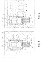
- Die Erfindung wird im Folgenden anhand der beiliegenden Zeichnung an einer Ausführungsform näher erläutert. Darin zeigt
- Fig. 1
- schematisch einen Querschnitt durch ein Gehäuse mit einer druckfluidführenden Leitung und einem in diese eingebauten Be- und Entlüftungsventil, und
- Fig. 2
- einen Längsschnitt durch das Gehäuse der Fig. 1.
- In einem Gehäuse 2, welches beispielsweise Teil eines Drucköl-Versorgungssystems für einen Verbrennungsmotor ist, befindet sich eine Versorgungsleitung 4, von der aus über Anschlussleitungen 6, 8 mit Drucköl zu versorgende, nicht dargestellte Aggregate versorgt werden. Die Versorgungsleitung 4 ist im Bereich ihrer Bodenwand 10 mit einer Entlüftungsbohrung 12 versehen, in die ein als Ganzes mit 14 bezeichnetes Ventil fluiddicht eingesetzt ist.
- Das Ventil 14 umfasst ein im Wesentlich kreiszylinderförmiges Ventilgehäuse 16, an dessen oberen Stirnseite eine Eingangsöffnung 18 und an dessen unteren Seite eine Ausgangsöffnung 20 ausgebildet ist. Das Ventilgehäuse 16 weist einen oberen, ersten Abschnitt 22 größeren Durchmessers und einen unteren, zweiten Abschnitt 24 kleineren Durchmessers auf. An der Innenwand des Ventilgehäuses 16 im Übergang vom ersten Abschnitt 22 zum zweiten Abschnitt 24 ist ein Ventilsitz 26 ausgebildet.
- Im Ventilgehäuse 16 ist ein Führungskäfig 28 angeordnet, in welchem ein in Richtung der Zylinderachse 30 des Ventils frei beweglicher, kugelförmiger Verschlusskörper 32 geführt ist. Der Verschlusskörper 32 ist zwischen einer am Ventilsitz 26 anliegenden Schließstellung und einer davon abgehobenen, durch einen an der Innenwand des Führungskäfigs 28 ausgebildeten Anschlag 34 definierten Öffnungsstellung beweglich.
- Der Verschlusskörper 32 wird im drucklosen Zustand des Versorgungssystems bzw. der Versorgungsleitung 4 durch Federmittel 36 in seine Öffnungsstellung gehalten. Die Federmittel 36 sind im vorliegenden Ausführungsbeispiel durch eine Schrauben-Druckfeder gebildet, die sich an einem an der Innenwand des zweiten Abschnittes 24 ausgebildeten Innenbund 38 abstützt.
- Im drucklosen Zustand des Versorgungssystems bzw. der Versorgungsleitung 4 wird der Verschlusskörper 32 durch die in Öffnungsrichtung wirkenden Federmittel 36 in seiner in den Figuren dargestellten, am Anschlag 34 anliegenden Öffnungsstellung gehalten. Wenn das Versorgungssystem wieder unter Druck gesetzt wird, wird zunächst die im oberen Bereich der Versorgungsleitung 4 angesammelte Luft über die Eingangsöffnung 18, das Ventilgehäuse 16 und die Ausgangsöffnung 20 in Richtung der dargestellten Pfeile aus der Versorgungsleitung 4 und dem Ventil ausgeschoben. Die dabei durch die ausströmende Luft auf den Verschlusskörper 32 ausgeübte Kraft und das Gewicht des Verschlusskörpers 32 reichen nicht aus, um die Federmittel 36 zusammenzudrücken und den Verschlusskörper 32 an den Ventilsitz 26 anzulegen.
- Wenn die im System vorhandene Luft ausgestoßen ist und Drucköl auf den Verschlusskörper 32 trifft, wird dieser infolge des höheren Druckes an den Ventilsitz 26 angelegt, so dass das Ventil sich schließt.
- Wenn der Druck in der Versorgungsleitung 4 nach dem Abstellen des Verbrennungsmotors wieder abfällt und das Drucköl infolge Abkühlung schrumpft, öffnet das Ventil 14 wieder, so dass das System gezielt an dieser Stelle belüftet wird.
- Wie die Figuren erkennen lassen, ist das Ventilgehäuse 16 so in die Versorgungsleitung 4 eingebaut, dass es nach oben möglichst weit in diese hineinragt und so einen bestimmten Pegelstand in der Versorgungsleitung 4 sicherstellt, so dass beim erneuten Anlauf des Systems bei Förderbeginn der Druckfluid-Pumpe eine Versorgung der an die Anschlussleitungen 6, 8 angeschlossenen Aggregate sichergestellt ist.
-
- 2
- Gehäuse
- 4
- Versorgungsleitung
- 6
- Anschlussleitung
- 8
- Anschlussleitung
- 10
- Bodenwand
- 12
- Entlüftungsbohrung
- 14
- Ventil
- 16
- Ventilgehäuse
- 18
- Eingangsöffnung
- 20
- Ausgangsöffnung
- 22
- Erster Abschnitt
- 24
- Zweiter Abschnitt
- 26
- Ventilsitz
- 28
- Führungskäfig
- 30
- Zylinderachse
- 32
- Verschlusskörper
- 34
- Anschlag
- 36
- Federmittel
- 38
- Innenbund
Claims (6)
- Vorrichtung zum Be- und Entlüften eines Druckfluid-Versorgungssystems, mit einem automatischen Ventil (14), welches einen gegen die Entlüftungsrichtung öffnenden Verschlusskörper (32) sowie diesem Verschlusskörper (32) zugeordnete, diesen in Öffnungsrichtung belastende Betätigungsmittel umfasst, die von auf den Verschlusskörper einwirkendem Druckfluid überdrückbar sind, dadurch gekennzeichnet, dass der Verschlusskörper (32) durch Federmittel (36) belastet ist, deren Auslegungs-Federkraft größer als eine durch einen ausströmenden Luftstrom auf den Verschlusskörper (32) aufgebrachte und gegebenenfalls durch eine in Schließrichtung wirkende Gewichtskomponente des Verschlusskörpers (32) erzeugte Gegenkraft ist.
- Vorrichtung nach Anspruch 1, dadurch gekennzeichnet, dass das Ventil (14) ein mit einer Eingangsöffnung (18) und einer Ausgangsöffnung (20) ausgestattetes Ventilgehäuse (16) mit einem darin zwischen einer an einem Ventilsitz (26) anliegenden Schließstellung und einer davon abgehobenen, durch einen Anschlag (34) definierten Öffnungsstellung beweglichen Verschlusskörper (32) umfasst.
- Vorrichtung nach Anspruch 2, dadurch gekennzeichnet, dass das Ventilgehäuse (16) im Wesentlichen die Form eines Kreiszylinders hat, an dessen einen Stirnseite die Eingangsöffnung (18) und an dessen anderer Stirnseite die Ausgangsöffnung (20) ausgebildet ist.
- Vorrichtung nach Anspruch 2, dadurch gekennzeichnet, dass der Kreiszylinder des Ventilgehäuses (16) in Entlüftungsrichtung nacheinander angeordnet einen ersten Abschnitt (22) größeren Durchmessers und einen zweiten Abschnitt (24) kleineren Durchmessers hat, dass der Verschlusskörper (32) im ersten Abschnitt (22) in Richtung der Zylinderachse (30) beweglich angeordnet ist und mit einem im Übergangsbereich zwischen erstem Abschnitt (22) und zweitem Abschnitt (24) ausgebildeten Ventilsitz (26) zusammenwirkt, und dass die Federmittel (36) eine Schrauben-Druckfeder umfassen, die zwischen dem Verschlusskörper (32) und einem an der Innenwand des zweiten Abschnittes (24) ausgebildeten Innenbund (38) angeordnet ist.
- Vorrichtung nach Anspruch 4, dadurch gekennzeichnet, dass der Verschlusskörper (32) eine Kugel ist, die in einem im ersten Abschnitt (22) angeordneten Führungskäfig (28) geführt ist, und dass der die Öffnungsstellung des Ventils (14) definierende Anschlag (34) an der Innenwand des Führungskäfigs (28) ausgebildet ist.
- Vorrichtung nach zumindest einem der Ansprüche 1 bis 5, dadurch gekennzeichnet, dass das Ventilgehäuse (16) in zumindest annähernd senkrechter Lage mit nach oben weisender Eingangsöffnung (18) in eine Bodenwand (10) einer druckfluidführenden Versorgungsleitung (4) oder dergleichen derart eingebaut ist, dass das Ventilgehäuse (16) nach oben in die Versorgungsleitung (4) hineinragt, und dass Anschlussleitungen (6, 8) für an das Versorgungssystem angeschlossene Verbraucher parallel zu dem Ventil (14) an die Bodenwand (10) der Versorgungsleitung (4) angeschlossen sind.
Applications Claiming Priority (1)
| Application Number | Priority Date | Filing Date | Title |
|---|---|---|---|
| DE200610030160 DE102006030160A1 (de) | 2006-06-29 | 2006-06-29 | Vorrichtung zum automatischen Be- und Entlüften eines Druckfluid-Versorgungssystems |
Publications (3)
| Publication Number | Publication Date |
|---|---|
| EP1873432A2 true EP1873432A2 (de) | 2008-01-02 |
| EP1873432A3 EP1873432A3 (de) | 2008-03-26 |
| EP1873432B1 EP1873432B1 (de) | 2011-08-10 |
Family
ID=38556436
Family Applications (1)
| Application Number | Title | Priority Date | Filing Date |
|---|---|---|---|
| EP20070110436 Not-in-force EP1873432B1 (de) | 2006-06-29 | 2007-06-18 | Vorrichtung zum automatischen Be- und Entlüften eines Druckfluid-Versorgungssystems |
Country Status (2)
| Country | Link |
|---|---|
| EP (1) | EP1873432B1 (de) |
| DE (1) | DE102006030160A1 (de) |
Cited By (1)
| Publication number | Priority date | Publication date | Assignee | Title |
|---|---|---|---|---|
| CN111828695A (zh) * | 2020-07-17 | 2020-10-27 | 阮勤林 | 深水环境下的密封舱充气密封阀门 |
Families Citing this family (1)
| Publication number | Priority date | Publication date | Assignee | Title |
|---|---|---|---|---|
| DE102011005406A1 (de) * | 2011-03-11 | 2012-09-13 | Zf Friedrichshafen Ag | Vorrichtung zur initialen Entlüftung von öl- und luftdichten Hydrauliksystemen |
Citations (1)
| Publication number | Priority date | Publication date | Assignee | Title |
|---|---|---|---|---|
| CH301104A (de) | 1952-02-20 | 1954-08-31 | Von Roll Ag | Automatisches Ventil zur Be- und Entlüftung von Rohrleitungen. |
Family Cites Families (9)
| Publication number | Priority date | Publication date | Assignee | Title |
|---|---|---|---|---|
| GB583550A (en) * | 1944-08-10 | 1946-12-20 | John Daniel Eldret Venning | Improvements in or relating to air or gas relief or vent valves |
| DE1901776C3 (de) * | 1969-01-15 | 1980-04-17 | Ermeto Armaturen Gmbh, 4800 Bielefeld | Vorrichtung zum selbsttätigen Entlüften von Hydraulikanlagen |
| FR2570158B1 (fr) * | 1984-09-07 | 1986-12-12 | Bayard Ets | Systeme de fermeture anticipee pour ventouse de reseau d'eau sous pression |
| DE3538670A1 (de) * | 1985-10-31 | 1987-05-07 | Kloeckner Humboldt Deutz Ag | Belueftung und entlueftung fuer ein gehaeuse |
| CH671075A5 (de) * | 1986-01-11 | 1989-07-31 | Lacrex Brevetti Sa | |
| JP2544115B2 (ja) * | 1986-08-05 | 1996-10-16 | バブ日立エンジニアリングサ−ビス株式会社 | ボイラ用ガス抜き弁 |
| GB9111327D0 (en) * | 1991-05-24 | 1991-07-17 | Pall Corp | Automatic bleed valves |
| EP0902751B1 (de) * | 1996-06-14 | 1999-10-27 | TRW Fahrwerksysteme GmbH & Co. KG | Verfahren zur entlüftung eines hydraulischen servolenksystems |
| DE20023895U1 (de) * | 2000-08-24 | 2007-03-15 | H. Schroeder & Co. Gmbh & Co. Kg | Entgasungsvorrichtung |
-
2006
- 2006-06-29 DE DE200610030160 patent/DE102006030160A1/de not_active Withdrawn
-
2007
- 2007-06-18 EP EP20070110436 patent/EP1873432B1/de not_active Not-in-force
Patent Citations (1)
| Publication number | Priority date | Publication date | Assignee | Title |
|---|---|---|---|---|
| CH301104A (de) | 1952-02-20 | 1954-08-31 | Von Roll Ag | Automatisches Ventil zur Be- und Entlüftung von Rohrleitungen. |
Cited By (1)
| Publication number | Priority date | Publication date | Assignee | Title |
|---|---|---|---|---|
| CN111828695A (zh) * | 2020-07-17 | 2020-10-27 | 阮勤林 | 深水环境下的密封舱充气密封阀门 |
Also Published As
| Publication number | Publication date |
|---|---|
| EP1873432A3 (de) | 2008-03-26 |
| DE102006030160A1 (de) | 2008-01-03 |
| EP1873432B1 (de) | 2011-08-10 |
Similar Documents
| Publication | Publication Date | Title |
|---|---|---|
| EP1654456B1 (de) | Kraftstoff-einspritzvorrichtung für eine brennkraftmaschine | |
| DE202015009446U1 (de) | Abtauventil mit großer Kapazität | |
| EP0010310A2 (de) | Absperrventil zur Kontrolle eines Flüssigkeitsstandes | |
| DE3887351T2 (de) | Wasserschlagabsorber. | |
| DE202015009445U1 (de) | Abtauventil | |
| DE1942230C3 (de) | Heißgasmotor | |
| EP1873432B1 (de) | Vorrichtung zum automatischen Be- und Entlüften eines Druckfluid-Versorgungssystems | |
| EP2603680B1 (de) | Einspritzvorrichtung zum einbringen einer harnstofflösung in den abgasstrang einer brennkraftmaschine | |
| DE102008014820A1 (de) | Kraftstofftank für Kraftfahrzeuge | |
| DE10107698C1 (de) | Gaswechselventileinrichtung für eine Brennkraftmaschine | |
| DE19821756A1 (de) | Antriebseinrichtung für eine Absperrvorrichtung in einer Rohrleitung | |
| DE102007030711A1 (de) | Injektor mit nach außen öffnendem Ventilelement | |
| DE10161438B4 (de) | Hubkolbenmaschine | |
| DE102019218400B4 (de) | Ventilkegel und Lasthalteventil mit Ventilkegel | |
| DE3802102C2 (de) | ||
| DE102010042755B4 (de) | Mit Druckluft betriebener Unterdruckerzeuger | |
| DE102021109524A1 (de) | Systemtrenner | |
| DE102019009464B4 (de) | Ventilkegel und Lasthalteventil mit Ventilkegel | |
| WO1992015810A1 (de) | Durchfluss-kontrollventil | |
| EP2757264A2 (de) | Verdichtereinheit und Kompressorsystem mit einer solchen | |
| DE566813C (de) | Vorrichtung zur Vermeidung gefaehrlicher Drucksteigerungen in Rohrleitungen | |
| DE102015221515B4 (de) | Ventilanordnung zur Begrenzung von Druckspitzen in einem Hydrauliksystem eines Automatikgetriebes | |
| DE2759900C2 (de) | Rückschlagventil mit Dämpfungseinrichtung | |
| DE102015117854B4 (de) | Kraftstoff-Einspritzinjektor mit einer verstellbaren Düsennadel | |
| DE19516560C2 (de) | Selbsttätiges Entwässerungsventil zum Ableiten von Kondensat aus Ausblaseleitungen nach Sicherheitsventilen, insbesondere an Dampferzeugern |
Legal Events
| Date | Code | Title | Description |
|---|---|---|---|
| PUAI | Public reference made under article 153(3) epc to a published international application that has entered the european phase |
Free format text: ORIGINAL CODE: 0009012 |
|
| 17P | Request for examination filed |
Effective date: 20070618 |
|
| AK | Designated contracting states |
Kind code of ref document: A2 Designated state(s): AT BE BG CH CY CZ DE DK EE ES FI FR GB GR HU IE IS IT LI LT LU LV MC MT NL PL PT RO SE SI SK TR |
|
| AX | Request for extension of the european patent |
Extension state: AL BA HR MK YU |
|
| PUAL | Search report despatched |
Free format text: ORIGINAL CODE: 0009013 |
|
| AK | Designated contracting states |
Kind code of ref document: A3 Designated state(s): AT BE BG CH CY CZ DE DK EE ES FI FR GB GR HU IE IS IT LI LT LU LV MC MT NL PL PT RO SE SI SK TR |
|
| AX | Request for extension of the european patent |
Extension state: AL BA HR MK YU |
|
| 17Q | First examination report despatched |
Effective date: 20080526 |
|
| AKX | Designation fees paid |
Designated state(s): DE ES FR GB IT |
|
| GRAP | Despatch of communication of intention to grant a patent |
Free format text: ORIGINAL CODE: EPIDOSNIGR1 |
|
| GRAS | Grant fee paid |
Free format text: ORIGINAL CODE: EPIDOSNIGR3 |
|
| RAP1 | Party data changed (applicant data changed or rights of an application transferred) |
Owner name: SCHAEFFLER TECHNOLOGIES GMBH & CO. KG |
|
| GRAA | (expected) grant |
Free format text: ORIGINAL CODE: 0009210 |
|
| AK | Designated contracting states |
Kind code of ref document: B1 Designated state(s): DE ES FR GB IT |
|
| REG | Reference to a national code |
Ref country code: GB Ref legal event code: FG4D Free format text: NOT ENGLISH |
|
| REG | Reference to a national code |
Ref country code: DE Ref legal event code: R096 Ref document number: 502007007896 Country of ref document: DE Effective date: 20111013 |
|
| RAP2 | Party data changed (patent owner data changed or rights of a patent transferred) |
Owner name: SCHAEFFLER TECHNOLOGIES AG & CO. KG |
|
| PLBE | No opposition filed within time limit |
Free format text: ORIGINAL CODE: 0009261 |
|
| STAA | Information on the status of an ep patent application or granted ep patent |
Free format text: STATUS: NO OPPOSITION FILED WITHIN TIME LIMIT |
|
| 26N | No opposition filed |
Effective date: 20120511 |
|
| REG | Reference to a national code |
Ref country code: DE Ref legal event code: R097 Ref document number: 502007007896 Country of ref document: DE Effective date: 20120511 |
|
| REG | Reference to a national code |
Ref country code: DE Ref legal event code: R081 Ref document number: 502007007896 Country of ref document: DE Owner name: SCHAEFFLER TECHNOLOGIES AG & CO. KG, DE Free format text: FORMER OWNER: SCHAEFFLER TECHNOLOGIES GMBH & CO. KG, 91074 HERZOGENAURACH, DE Effective date: 20120828 Ref country code: DE Ref legal event code: R081 Ref document number: 502007007896 Country of ref document: DE Owner name: SCHAEFFLER TECHNOLOGIES GMBH & CO. KG, DE Free format text: FORMER OWNER: SCHAEFFLER TECHNOLOGIES GMBH & CO. KG, 91074 HERZOGENAURACH, DE Effective date: 20120828 |
|
| PG25 | Lapsed in a contracting state [announced via postgrant information from national office to epo] |
Ref country code: ES Free format text: LAPSE BECAUSE OF FAILURE TO SUBMIT A TRANSLATION OF THE DESCRIPTION OR TO PAY THE FEE WITHIN THE PRESCRIBED TIME-LIMIT Effective date: 20111121 |
|
| REG | Reference to a national code |
Ref country code: DE Ref legal event code: R081 Ref document number: 502007007896 Country of ref document: DE Owner name: SCHAEFFLER TECHNOLOGIES AG & CO. KG, DE Free format text: FORMER OWNER: SCHAEFFLER TECHNOLOGIES AG & CO. KG, 91074 HERZOGENAURACH, DE Effective date: 20140218 Ref country code: DE Ref legal event code: R081 Ref document number: 502007007896 Country of ref document: DE Owner name: SCHAEFFLER TECHNOLOGIES GMBH & CO. KG, DE Free format text: FORMER OWNER: SCHAEFFLER TECHNOLOGIES AG & CO. KG, 91074 HERZOGENAURACH, DE Effective date: 20140218 |
|
| REG | Reference to a national code |
Ref country code: DE Ref legal event code: R081 Ref document number: 502007007896 Country of ref document: DE Owner name: SCHAEFFLER TECHNOLOGIES AG & CO. KG, DE Free format text: FORMER OWNER: SCHAEFFLER TECHNOLOGIES GMBH & CO. KG, 91074 HERZOGENAURACH, DE Effective date: 20150223 |
|
| REG | Reference to a national code |
Ref country code: FR Ref legal event code: PLFP Year of fee payment: 9 |
|
| REG | Reference to a national code |
Ref country code: FR Ref legal event code: PLFP Year of fee payment: 10 |
|
| PGFP | Annual fee paid to national office [announced via postgrant information from national office to epo] |
Ref country code: GB Payment date: 20160630 Year of fee payment: 10 |
|
| PGFP | Annual fee paid to national office [announced via postgrant information from national office to epo] |
Ref country code: FR Payment date: 20160630 Year of fee payment: 10 |
|
| PGFP | Annual fee paid to national office [announced via postgrant information from national office to epo] |
Ref country code: IT Payment date: 20160623 Year of fee payment: 10 Ref country code: DE Payment date: 20160831 Year of fee payment: 10 |
|
| REG | Reference to a national code |
Ref country code: DE Ref legal event code: R119 Ref document number: 502007007896 Country of ref document: DE |
|
| GBPC | Gb: european patent ceased through non-payment of renewal fee |
Effective date: 20170618 |
|
| REG | Reference to a national code |
Ref country code: FR Ref legal event code: ST Effective date: 20180228 |
|
| PG25 | Lapsed in a contracting state [announced via postgrant information from national office to epo] |
Ref country code: GB Free format text: LAPSE BECAUSE OF NON-PAYMENT OF DUE FEES Effective date: 20170618 Ref country code: DE Free format text: LAPSE BECAUSE OF NON-PAYMENT OF DUE FEES Effective date: 20180103 |
|
| PG25 | Lapsed in a contracting state [announced via postgrant information from national office to epo] |
Ref country code: IT Free format text: LAPSE BECAUSE OF NON-PAYMENT OF DUE FEES Effective date: 20170618 Ref country code: FR Free format text: LAPSE BECAUSE OF NON-PAYMENT OF DUE FEES Effective date: 20170630 |
|
| P01 | Opt-out of the competence of the unified patent court (upc) registered |
Effective date: 20230522 |