EP1873000A2 - Adjustable steering column assembly having an attached instrument cluster - Google Patents
Adjustable steering column assembly having an attached instrument cluster Download PDFInfo
- Publication number
- EP1873000A2 EP1873000A2 EP07075489A EP07075489A EP1873000A2 EP 1873000 A2 EP1873000 A2 EP 1873000A2 EP 07075489 A EP07075489 A EP 07075489A EP 07075489 A EP07075489 A EP 07075489A EP 1873000 A2 EP1873000 A2 EP 1873000A2
- Authority
- EP
- European Patent Office
- Prior art keywords
- rake
- bracket
- assembly
- mounting bracket
- set forth
- Prior art date
- Legal status (The legal status is an assumption and is not a legal conclusion. Google has not performed a legal analysis and makes no representation as to the accuracy of the status listed.)
- Withdrawn
Links
Images




Classifications
-
- B—PERFORMING OPERATIONS; TRANSPORTING
- B62—LAND VEHICLES FOR TRAVELLING OTHERWISE THAN ON RAILS
- B62D—MOTOR VEHICLES; TRAILERS
- B62D1/00—Steering controls, i.e. means for initiating a change of direction of the vehicle
- B62D1/02—Steering controls, i.e. means for initiating a change of direction of the vehicle vehicle-mounted
- B62D1/16—Steering columns
- B62D1/18—Steering columns yieldable or adjustable, e.g. tiltable
- B62D1/187—Steering columns yieldable or adjustable, e.g. tiltable with tilt adjustment; with tilt and axial adjustment
-
- B—PERFORMING OPERATIONS; TRANSPORTING
- B60—VEHICLES IN GENERAL
- B60K—ARRANGEMENT OR MOUNTING OF PROPULSION UNITS OR OF TRANSMISSIONS IN VEHICLES; ARRANGEMENT OR MOUNTING OF PLURAL DIVERSE PRIME-MOVERS IN VEHICLES; AUXILIARY DRIVES FOR VEHICLES; INSTRUMENTATION OR DASHBOARDS FOR VEHICLES; ARRANGEMENTS IN CONNECTION WITH COOLING, AIR INTAKE, GAS EXHAUST OR FUEL SUPPLY OF PROPULSION UNITS IN VEHICLES
- B60K35/00—Instruments specially adapted for vehicles; Arrangement of instruments in or on vehicles
- B60K35/50—Instruments characterised by their means of attachment to or integration in the vehicle
-
- B—PERFORMING OPERATIONS; TRANSPORTING
- B62—LAND VEHICLES FOR TRAVELLING OTHERWISE THAN ON RAILS
- B62D—MOTOR VEHICLES; TRAILERS
- B62D1/00—Steering controls, i.e. means for initiating a change of direction of the vehicle
- B62D1/02—Steering controls, i.e. means for initiating a change of direction of the vehicle vehicle-mounted
- B62D1/16—Steering columns
- B62D1/18—Steering columns yieldable or adjustable, e.g. tiltable
- B62D1/19—Steering columns yieldable or adjustable, e.g. tiltable incorporating energy-absorbing arrangements, e.g. by being yieldable or collapsible
- B62D1/195—Yieldable supports for the steering column
-
- B—PERFORMING OPERATIONS; TRANSPORTING
- B60—VEHICLES IN GENERAL
- B60K—ARRANGEMENT OR MOUNTING OF PROPULSION UNITS OR OF TRANSMISSIONS IN VEHICLES; ARRANGEMENT OR MOUNTING OF PLURAL DIVERSE PRIME-MOVERS IN VEHICLES; AUXILIARY DRIVES FOR VEHICLES; INSTRUMENTATION OR DASHBOARDS FOR VEHICLES; ARRANGEMENTS IN CONNECTION WITH COOLING, AIR INTAKE, GAS EXHAUST OR FUEL SUPPLY OF PROPULSION UNITS IN VEHICLES
- B60K2360/00—Indexing scheme associated with groups B60K35/00 or B60K37/00 relating to details of instruments or dashboards
- B60K2360/60—Structural details of dashboards or instruments
- B60K2360/68—Features of instruments
- B60K2360/685—Instruments movable with steering column
-
- B—PERFORMING OPERATIONS; TRANSPORTING
- B60—VEHICLES IN GENERAL
- B60K—ARRANGEMENT OR MOUNTING OF PROPULSION UNITS OR OF TRANSMISSIONS IN VEHICLES; ARRANGEMENT OR MOUNTING OF PLURAL DIVERSE PRIME-MOVERS IN VEHICLES; AUXILIARY DRIVES FOR VEHICLES; INSTRUMENTATION OR DASHBOARDS FOR VEHICLES; ARRANGEMENTS IN CONNECTION WITH COOLING, AIR INTAKE, GAS EXHAUST OR FUEL SUPPLY OF PROPULSION UNITS IN VEHICLES
- B60K35/00—Instruments specially adapted for vehicles; Arrangement of instruments in or on vehicles
- B60K35/70—Instrument provisions for avoiding injuries to vehicle occupants in case of accidents
Definitions
- Modem vehicles incorporate a collapsible column jacket into the adjustable steering column assemblies, and further include energy absorption mechanisms.
- the energy absorption mechanisms absorb energy transmitted through the steering column as the steering column collapses along a longitudinal axis in response to an emergency event, such as a vehicular crash.
- the effectiveness of the energy absorption mechanism is reduced or eliminated by having the instrument cluster permanently mounted to the steering column assembly because the instrument cluster abuts against the instrument panel, thereby restricting movement of the collapsible column jacket. Additionally, the added weight of the instrument cluster onto the steering column assembly increases vibration of the steering column assembly felt by the driver, which is an undesirable effect.
- FIG. 2 is a side view of the steering column assembly shown in Figure 1;
- the linear spring 48 includes a cluster bracket 46.
- the cluster bracket 46 includes a flange 50 interconnecting the cluster bracket 46 and the instrument cluster 38. Accordingly, it should be understood that the outer casing 40 is attached to the flange 50 of the cluster bracket 46.
- the instrument cluster 38 is fixedly mounted to the dynamic absorber 44, and is therefore stationary relative to the mounting bracket 26 in response to the emergency event. It should be understood that the dynamic absorber 44 may include some other device capable of reducing vibration in the column jacket 24. Accordingly, the scope of the claims should not be limited to the exact configuration of the dynamic absorber 44 described herein.
Landscapes
- Engineering & Computer Science (AREA)
- Chemical & Material Sciences (AREA)
- Combustion & Propulsion (AREA)
- Transportation (AREA)
- Mechanical Engineering (AREA)
- Steering Controls (AREA)
Abstract
Description
- The subject invention generally relates to a steering column assembly for a vehicle.
- Vehicles typically include an instrument panel attached to a cross beam extending between a pair of front pillars. An instrument cluster is usually attached to the instrument panel, and is typically located above a steering column assembly. The instrument cluster includes instrumentation necessary for a driver to properly operate the vehicle, such as a speedometer, tachometer, fuel gauge, coolant temperature gauge, etc. The driver views the instrumentation by looking through and around a steering wheel attached to the steering column.
- Currently, many vehicles are equipped with adjustable steering column assemblies. The adjustable steering column assemblies may include rake adjustments for adjusting the height of the steering wheel, telescopic adjustments for adjusting the distance of the steering wheel from the driver, or may include both the rake adjustment and the telescopic adjustment. Accordingly, the steering wheel may be positioned in a manner that obstructs the view of the instrumentation of the instrument cluster.
- Mounting the instrument cluster on the steering column allows the instrument cluster to move with the steering column in both the rake and the telescoping adjustments. Accordingly, the instrument cluster maintains a fixed spatial relationship relative to the steering wheel, thereby ensuring the driver has a continuous unobstructed view of the instrument cluster regardless of the position of the steering wheel.
United States Patent No. 4,527, 444 discloses a steering column assembly having both rake and telescopic adjustments with the instrument cluster permanently mounted to the steering column assembly. - Modem vehicles incorporate a collapsible column jacket into the adjustable steering column assemblies, and further include energy absorption mechanisms. The energy absorption mechanisms absorb energy transmitted through the steering column as the steering column collapses along a longitudinal axis in response to an emergency event, such as a vehicular crash.
- However, the effectiveness of the energy absorption mechanism is reduced or eliminated by having the instrument cluster permanently mounted to the steering column assembly because the instrument cluster abuts against the instrument panel, thereby restricting movement of the collapsible column jacket. Additionally, the added weight of the instrument cluster onto the steering column assembly increases vibration of the steering column assembly felt by the driver, which is an undesirable effect.
- The subject invention discloses a steering column assembly for a vehicle. The steering column assembly comprises a mounting bracket for attaching the steering column assembly to the vehicle. A rake bracket is coupled to the mounting bracket, and is pivotable relative to the mounting bracket about a rake axis. The rake bracket extends from the mounting bracket along a longitudinal axis to a distal end. A column jacket is supported by the mounting bracket and detachable supported by the rake bracket. The column jacket is longitudinally moveable relative to the mounting bracket along the longitudinal axis in response to an emergency event. The column jacket is also pivotably moveable with the rake bracket relative to the mounting bracket about the rake axis. An instrument cluster is coupled to the distal end of the rake bracket. The instrument cluster is rotatably moveable with the rake bracket and the column jacket relative to the mounting bracket about the rake axis.
- Accordingly, the subject invention provides a steering column assembly in which the instrument cluster is coupled to the rake bracket. The instrument cluster moves with the rake bracket as the steering column assembly is adjusted about the rake axis to maintain an unobstructed view of the instrument cluster. The instrument cluster is not directly mounted onto the column jacket and therefore does not interfere with the collapse of the column jacket in response to the emergency event.
- Other advantages of the present invention will be readily appreciated, as the same becomes better understood by reference to the following detailed description when considered in connection with the accompanying drawings wherein:
- Figure 1 is a perspective view of a steering column assembly;
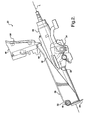
- Figure 2 is a side view of the steering column assembly shown in Figure 1;
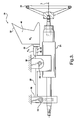
- Figure 3 is a schematic side view of the steering column assembly;
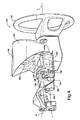
- Figure 4 is a perspective view of a first alternative embodiment of the steering column assembly;
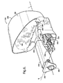
- Figure 5 is a partial fragmentary perspective view of the first alternative embodiment of the steering column assembly shown in Figure 4;
- Figure 6 is a perspective view of a second alternative embodiment of the steering column assembly;
- Figures 7 is a partial perspective view of the second alternative embodiment of the steering column assembly shown in Figure 6;and
- Figure 8 is fragmentary cross sectional perspective view of the second alternative embodiment of the steering column assembly shown in Figure 6.
- Referring to the Figures, wherein like numerals indicate corresponding parts throughout the several views, a steering column assembly is generally shown at 20. The
steering column assembly 20 is for a vehicle, and includes anenergy absorption mechanism 22. Theenergy absorption mechanism 22 absorbs energy transmitted through acolumn jacket 24 in response to an emergency event. The emergency event typically includes a vehicular impact. Theenergy absorption mechanism 22 reduces the amount of energy transmitted through thesteering column assembly 20, thereby reducing injury to a driver. There are severalenergy absorption mechanisms 22 known in the art capable of absorbing energy transmitted through thesteering column assembly 20 that may be incorporated into the subject invention. Accordingly, theenergy absorption mechanism 22 is not described in detail herein, and the scope of the claims should not be limited to the exact configuration or type ofenergy absorption mechanism 22 utilized. - Referring to Figures 1 and 2, the
steering column assembly 20 comprises amounting bracket 26 for attachment to the vehicle. Arake bracket 28 is coupled to themounting bracket 26 and also to the vehicle. Therake bracket 28 is pivotable relative to themounting bracket 26 about a rake axis R, and extends from themounting bracket 26 along a longitudinal axis L to adistal end 30. Themounting bracket 26 includes ahinge 32 extending transverse to the longitudinal axis L, with thehinge 32 defining the rake axis R therethrough. - The
steering column assembly 20 further comprises arake adjustment mechanism 34. Therake adjustment mechanism 34 rotationally adjusts thecolumn jacket 24 and therake bracket 28 about the rake axis R relative to themounting bracket 26. Therake adjustment mechanism 34 also locks thecolumn jacket 24 and therake bracket 28 in position relative to themounting bracket 26. There are several knownrake adjustment mechanisms 34 capable of adjusting and locking the rake position of thecolumn jacket 24 and therake bracket 28 that may be incorporated into the subject invention. Accordingly, therake adjustment mechanism 34 is not described in detail herein, and the scope of the claims should not be limited to the exact configuration or type ofrake adjustment mechanism 34 utilized. - The
column jacket 24 is supported by themounting bracket 26 and detachably supported by therake bracket 28. Thecolumn jacket 24 is longitudinally moveable relative to themounting bracket 26 along the longitudinal axis L in response to an emergency event, i.e., thecolumn jacket 24 is collapsible in response to an emergency event. Thecolumn jacket 24 is also pivotably moveable with therake bracket 28 relative to themounting bracket 26 about the rake axis R. Asteering wheel 36 is attached to an end of thecolumn jacket 24 as is well known in the art. - An
instrument cluster 38 is coupled to thedistal end 30 of therake bracket 28. Theinstrument cluster 38 is rotatably moveable with therake bracket 28 and thecolumn jacket 24 relative to themounting bracket 26 about the rake axis R. Theinstrument cluster 38 includes anouter casing 40, preferably manufactured from a plastic material. At least onegauge 42, and preferably a plurality ofgauges 42 are supported by theouter casing 40. Thegauges 42 typically include a speedometer, a tachometer, a fuel gauge, a temperature gauge, an oil pressure gauge, etc. It should be understood that the number and kind of gauges may vary depending upon the vehicular requirements, and that the scope of the claims are not limited to the number and kind of gauges. - Referring also to Figure 3, which is a schematic representation of the
steering column assembly 20, thesteering column assembly 20 further comprises adynamic absorber 44 interconnecting theinstrument cluster 38 and therake bracket 28. Thecolumn jacket 24 and the attachedsteering wheel 36 vibrate at a resonance frequency as is well known in the art. Thedynamic absorber 44 reduces the vibration transmitted to theinstrument cluster 38 and also the vibration in thesteering wheel 36. Preferably, thedynamic absorber 44 includes alinear spring 48 having a pre-determined spring constant Kz. Thelinear spring 48 supports theinstrument cluster 38, which includes a mass Mz. Thedynamic absorber 44 and theinstrument cluster 38 are therefore cantilevered from therake bracket 28. Accordingly, the mass Mz of theinstrument cluster 38 is coupled to therake bracket 28 by the spring constant Kz and cooperate together to counteract the vibration in thecolumn jacket 24 to reduce the overall vibration in theinstrument cluster 38 and thesteering wheel 36. Thelinear spring 48 includes acluster bracket 46. Thecluster bracket 46 includes aflange 50 interconnecting thecluster bracket 46 and theinstrument cluster 38. Accordingly, it should be understood that theouter casing 40 is attached to theflange 50 of thecluster bracket 46. Theinstrument cluster 38 is fixedly mounted to thedynamic absorber 44, and is therefore stationary relative to the mountingbracket 26 in response to the emergency event. It should be understood that thedynamic absorber 44 may include some other device capable of reducing vibration in thecolumn jacket 24. Accordingly, the scope of the claims should not be limited to the exact configuration of thedynamic absorber 44 described herein. - As depicted in the embodiment shown in Figures 1 and 2 with reference to the schematic representation shown in Figure 3, the
dynamic absorber 44 is integral with therake bracket 28. As such, thelinear spring 48 is an extension of therake bracket 28. The pre-determined spring constant Kz is therefore dependent upon the geometric design of thedynamic absorber 44 and the material utilized to manufacture thedynamic absorber 44. As is known in the art, the ability to reduce vibration is a factor of the spring constant Kz and the mass Mz of the object interconnected by thedynamic absorber 44. Accordingly, the effect on vibration in thesteering column assembly 20 by thedynamic absorber 44 is dependent upon the mass Mz of theinstrument cluster 38 and the spring constant Kz of thedynamic absorber 44. Knowing the mass of theinstrument cluster 38 and the physical properties of the material utilized for thedynamic absorber 44, one skilled in the art can customize the exact shape and configuration of thedynamic absorber 44 to best fit the specific design considerations and requirements. - It should be understood that upon an emergency event, the
column jacket 24 collapses along the longitudinal axis L. As thecolumn jacket 24 collapses, thecolumn jacket 24 detaches from therake bracket 28 as is well known in the art. Accordingly, theinstrument cluster 38 remains fixed in place, continuously attached to therake bracket 28 and stationary relative to the mountingbracket 26 and the instrument panel, thereby permitting proper operation of thecollapsible column jacket 24 and theenergy absorption mechanism 22. - A first alternative embodiment of the steering column assembly is generally shown at 120 in Figures 4 and 5. A second alternative embodiment of the steering column assembly is generally shown at 220 in Figures 6 through 8. Features of the
steering column assembly 20 shown in Figures 1 and 2 that correspond to Features of the first alternative embodiment shown in Figures 4 and 5 are represented by the same reference numeral preceded by the numeral "1". Accordingly, thesteering column assembly 20 shown in Figures 1 and 2 is referenced in the first alternative embodiment as thesteering column assembly 120. Likewise, features of thesteering column assembly 20 shown in Figures 1 and 2 that correspond to features of the second alternative embodiment shown in Figures 6 through 8 are represented by the same reference numeral preceded by the numeral "2". Accordingly, thesteering column assembly 20 shown in Figures 1 and 2 is referenced in the second alternative embodiment as thesteering column assembly 220. - Both the first and second alternative embodiments of the
steering column assembly telescoping mechanism telescoping mechanism column jacket telescoping mechanism column jacket bracket telescoping mechanisms column jacket telescoping mechanism telescoping mechanism - Referring to the first alternative embodiment shown in Figures 4 and 5, the
rake bracket 128 is axially adjustable along the longitudinal axis L with thecolumn jacket 124. Therake bracket 128 is in telescopic engagement with the mountingbracket 126 for axial movement along the longitudinal axis L relative to the mountingbracket 126. Thedynamic absorber 144 is fixedly mounted to therake bracket 128, and theinstrument cluster 138 is fixedly mounted to thedynamic absorber 144. It should be understood that thedynamic absorber 144 of the first alternative embodiment is identical to and operates in the same manner as thedynamic absorber 44 described in relation to Figures 1 through 3. - The
steering column assembly 120 of the first alternative embodiment allows theinstrument cluster 138 to move with thecolumn jacket 124 in both the rake direction and the telescoping direction during normal use. In response to the emergency event, thecolumn jacket 124 collapses. As thecolumn jacket 124 collapses, thecolumn jacket 124 detaches from therake bracket 128 and theinstrument cluster 138. Theinstrument cluster 138, being fixedly mounted to therake bracket 128 via thedynamic absorber 144, remains stationary relative to the mountingbracket 126 and the instrument panel, thereby permitting proper operation of thecollapsible column jacket 124 and theenergy absorption mechanism 122. - Referring to the second alternative embodiment shown in Figures 6 through 8, the
dynamic absorber 244 includes anarm 254 in telescopic engagement with therake bracket 228. Theinstrument cluster 238 is fixedly mounted to thedynamic absorber 244 and is axially moveable with thedynamic absorber 244 along the longitudinal axis L relative to the mountingbracket 226 in response to the emergency event. Thedynamic absorber 244 defines anotch 256, and arelease capsule 258 is disposed in thenotch 256. Apin 260 extends through thecolumn jacket 224, therelease capsule 258 and therake bracket 228 for interconnecting thecolumn jacket 224, thedynamic absorber 244, and therake bracket 228. It should be understood that thedynamic absorber 244 of the second alternative embodiment is identical to and operates in the same manner as thedynamic absorber 44 described in relation to Figures 1 through 3. - The
steering column assembly 220 of the second alternative embodiment allows theinstrument cluster 238 to move with thecolumn jacket 224 in both the rake direction and the telescoping direction during normal use. In response to the emergency event, thecolumn jacket 224 collapses. As thecolumn jacket 224 collapses, thedynamic absorber 244 and thecolumn jacket 224 remain coupled together, and both thecolumn jacket 224 and thedynamic absorber 244 detach from therake bracket 228. Accordingly, both thecolumn jacket 224 and thedynamic absorber 244 collapse, and theinstrument cluster 238 thereby moves relative to the mountingbracket 226 and the instrument panel during the emergency event. - The invention has been described in an illustrative manner, and it is to be understood that the terminology which has been used is intended to be in the nature of words of description rather than of limitation. As is now apparent to those skilled in the art, many modifications and variations of the present invention are possible in light of the above teachings. It is, therefore, to be understood that within the scope of the appended claims, wherein reference numerals are merely for convenience and are not to be in any way limiting, the invention may be practiced otherwise than as specifically described.
Claims (18)
- A steering column assembly (20, 120, 220) for a vehicle, said assembly (20, 120, 220) comprising:a mounting bracket (26, 126, 226) for attachment to the vehicle; a rake bracket (28, 128, 228) coupled to said mounting bracket (26, 126, 226) and pivotable relative to said mounting bracket (26, 126, 226) about a rake axis (R) with said rake bracket (28) extending from said mounting bracket (26, 126, 226) along a longitudinal axis (L) to a distal end (30, 130, 230);a column jacket (24, 124, 224) supported by said mounting bracket (26, 126, 226) and detachably supported by said rake bracket (28, 128, 228) and longitudinally moveable relative to said mounting bracket (26, 126, 226) along said longitudinal axis (L) in response to an emergency event and pivotably moveable with said rake bracket (28, 128, 228) relative to said mounting bracket (26, 126, 226) about said rake axis (R); andan instrument cluster (38, 138, 238) coupled to said distal end (30, 130, 230) of said rake bracket (28, 128, 228) and rotatably moveable with said rake bracket (28, 128, 228) and said column jacket (24, 124, 224) relative to said mounting bracket (26, 126, 226) about said rake axis (R).
- An assembly (20, 120, 220) as set forth in claim 1 further including a dynamic absorber (44, 144, 244) interconnecting said instrument cluster (38, 138, 238) and said rake bracket (28, 128, 238) for reducing vibration transmitted to said instrument cluster (38, 138, 238).
- An assembly (20, 120, 220) as set forth in claim 2 wherein said dynamic absorber (44, 144, 244) includes a linear spring (48, 148, 248) having a pre-determined spring constant (Kz).
- An assembly (20, 120, 220) as set forth in claim 3 wherein said linear spring (48, 148, 248) includes a cluster bracket (46, 146, 246) having a flange (50, 150, 250) interconnecting said cluster bracket (46, 146, 246) and said instrument cluster (38, 138, 238).
- An assembly (20, 120, 220) as set forth in claim 4 wherein said instrument cluster (38, 138, 238) includes an outer casing (40, 140, 240) and at least one gauge (42, 142, 242) supported by said outer casing (40, 140, 240) with said outer casing (40, 140, 240) attached to said flange (50, 150, 250) of said cluster bracket (46, 146, 246).
- An assembly (20, 120, 220) as set forth in claim 1 wherein said mounting bracket (26, 126, 226) includes a hinge (32, 132, 232) extending transverse to said longitudinal axis (L) and defining said rake axis (R).
- An assembly (20, 120, 220) as set forth in claim 1 further comprising a rake adjustment mechanism (34, 134, 234) for rotationally adjusting said column jacket (24, 124, 224) and said rake bracket (28, 128, 228) about said rake axis (R) relative to said mounting bracket (26, 126, 226) and locking said column jacket (24, 124, 224) and said rake bracket (28, 128, 228) relative to said mounting bracket (26, 126, 226).
- An assembly (20, 120, 220) as set forth in claim 1 further comprising an energy absorption mechanism (22, 122, 222) for absorbing energy transmitted through the column jacket (24, 124, 224) in response to the emergency event.
- An assembly (120, 220) as set forth in claim 2 further comprising a telescoping mechanism (152, 252) for adjusting said column jacket (124, 224) axially along said longitudinal axis (L) and locking said column jacket (124, 224) relative to said mounting bracket (126, 226).
- An assembly (120, 220) as set forth in claim 9 wherein said rake bracket (128, 228) is axially adjustable along said longitudinal axis (L) with said column jacket (124, 224).
- An assembly (120) as set forth in claim 10 wherein said instrument cluster (138) is fixedly mounted to said dynamic absorber (144) and stationary relative to said mounting bracket (126) in response to the emergency event.
- An assembly (220) as set forth in claim 9 wherein said rake bracket (228) is in telescopic engagement with said mounting bracket (226) for axial movement along said longitudinal axis (L) relative to said mounting bracket (226).
- An assembly (220) as set forth in claim 12 wherein said dynamic absorber (244) includes an arm (254) in telescopic engagement with said rake bracket (228).
- An assembly (220) as set forth in claim 13 wherein said instrument cluster (238) is fixedly mounted to said dynamic absorber (244) and axially moveable with said dynamic absorber (244) along said longitudinal axis (L) relative to said mounting bracket (226) in response to the emergency event.
- An assembly (220) as set forth in claim 13 wherein said dynamic absorber (244) defines a notch (256).
- An assembly (220) as set forth in claim 15 further comprising a release capsule (258) disposed in said notch (256) and a pin (260) extending through said column jacket (224), said release capsule (258) and said rake bracket (228) for interconnecting said column jacket (224), said dynamic absorber (244), and said rake bracket (228).
- An assembly (20) as set forth in claim 2 wherein said dynamic absorber (44) is fixedly mounted to said rake bracket (28).
- An assembly (20) as set forth in claim 17 wherein said instrument cluster (38) is fixedly mounted to said dynamic absorber (44) and stationary relative to said mounting bracket (26) in response to the emergency event.
Applications Claiming Priority (2)
| Application Number | Priority Date | Filing Date | Title |
|---|---|---|---|
| US81617406P | 2006-06-23 | 2006-06-23 | |
| US11/728,072 US7611165B2 (en) | 2006-06-23 | 2007-03-23 | Adjustable steering column assembly having an attached instrument cluster |
Publications (2)
| Publication Number | Publication Date |
|---|---|
| EP1873000A2 true EP1873000A2 (en) | 2008-01-02 |
| EP1873000A3 EP1873000A3 (en) | 2009-07-08 |
Family
ID=38442100
Family Applications (1)
| Application Number | Title | Priority Date | Filing Date |
|---|---|---|---|
| EP07075489A Withdrawn EP1873000A3 (en) | 2006-06-23 | 2007-06-20 | Adjustable steering column assembly having an attached instrument cluster |
Country Status (2)
| Country | Link |
|---|---|
| US (1) | US7611165B2 (en) |
| EP (1) | EP1873000A3 (en) |
Cited By (2)
| Publication number | Priority date | Publication date | Assignee | Title |
|---|---|---|---|---|
| FR2928897A1 (en) * | 2008-03-19 | 2009-09-25 | Peugeot Citroen Automobiles Sa | Fascia crosspiece and steering column assembly for motor vehicle, has fascia crosspiece connected to steering column by support, such that crosspiece passes under steering column, where support is connected to main tube of crosspiece |
| ITMI20120566A1 (en) * | 2012-04-06 | 2013-10-07 | Italdesign Giugiaro Spa | STEERING WHEEL SUPPORT FOR MOTOR VEHICLES |
Families Citing this family (9)
| Publication number | Priority date | Publication date | Assignee | Title |
|---|---|---|---|---|
| DE602008002297D1 (en) * | 2007-10-02 | 2010-10-07 | Daikyonishikawa Corp | Structure of the dashboard area in a vehicle |
| FR2990180B1 (en) * | 2012-05-04 | 2016-01-01 | Faurecia Interieur Ind | APPEARANCE ASSEMBLY FOR A VEHICLE FOR HIDING A TECHNICAL SPACE |
| JP6064612B2 (en) * | 2013-01-18 | 2017-01-25 | トヨタ自動車株式会社 | Instrument panel structure |
| US9963035B2 (en) * | 2016-02-05 | 2018-05-08 | Ford Global Technologies, Llc | Removable steering wheel and pedals for autonomous vehicle |
| CN106218412B (en) * | 2016-08-18 | 2018-12-18 | 江苏金坛长荡湖新能源科技有限公司 | A kind of combination instrument structure not influencing the visual field and its installation method |
| DE102018101538A1 (en) * | 2018-01-24 | 2019-07-25 | Jungheinrich Aktiengesellschaft | Truck |
| JP7190713B2 (en) * | 2018-07-05 | 2022-12-16 | パナソニックIpマネジメント株式会社 | Image display device and optical equipment |
| CN114084221A (en) * | 2021-12-08 | 2022-02-25 | 芜湖恒隆汽车转向系统有限公司 | Anti-overturning design structure of steering column |
| FR3167085A1 (en) * | 2024-10-08 | 2026-04-10 | Stellantis Auto Sas | SCREEN DISPLAY DEVICE FOLLOWING THE STEERING COLUMN OF A VEHICLE |
Family Cites Families (14)
| Publication number | Priority date | Publication date | Assignee | Title |
|---|---|---|---|---|
| JPS59501307A (en) * | 1982-07-21 | 1984-07-26 | ジエイ アイ ケイス コムパニ− | Tiltable and telescoping steering wheel system |
| US4690432A (en) * | 1984-10-24 | 1987-09-01 | Mazda Motor Corporation | Automobile instrument cluster tiltable with a steering column |
| JPH0747227Y2 (en) * | 1989-06-30 | 1995-11-01 | マツダ株式会社 | Car instrument panel structure |
| US5088571A (en) * | 1990-12-17 | 1992-02-18 | General Motors Corporation | Modular structural instrument panel carrier |
| US5461361A (en) * | 1994-03-11 | 1995-10-24 | Chrysler Corporation | Automotive instrument panel apparatus |
| US5497675A (en) * | 1994-06-06 | 1996-03-12 | Chrysler Corporation | Energy absorber for a steering column |
| US6223620B1 (en) * | 1999-04-08 | 2001-05-01 | Daimlerchrysler Corporation | Tilt release system for a steering column |
| US6419269B1 (en) * | 1999-09-20 | 2002-07-16 | Delphi Technologies | Locking system for adjustable position steering column |
| JP2003127874A (en) * | 2001-10-23 | 2003-05-08 | Fuji Kiko Co Ltd | Shock absorbing tilt steering column |
| US7128342B2 (en) * | 2003-01-31 | 2006-10-31 | Delphi Technologies, Inc. | Linear tracking knee bolster assembly |
| US20050151361A1 (en) * | 2004-01-14 | 2005-07-14 | Mazda Motor Corporation | Steering support structure of vehicle |
| US6843521B1 (en) * | 2004-02-25 | 2005-01-18 | General Motors Corporation | Pivoting instrument panel central stack structure and method for flow-through instrument panel console interface |
| US7484430B2 (en) * | 2004-07-27 | 2009-02-03 | Delphi Technologies, Inc. | Telescope feature used for energy absorption |
| US20060273568A1 (en) * | 2005-06-01 | 2006-12-07 | Manwaring Marvin V | Adaptive energy absorber for steering column |
-
2007
- 2007-03-23 US US11/728,072 patent/US7611165B2/en not_active Expired - Fee Related
- 2007-06-20 EP EP07075489A patent/EP1873000A3/en not_active Withdrawn
Cited By (2)
| Publication number | Priority date | Publication date | Assignee | Title |
|---|---|---|---|---|
| FR2928897A1 (en) * | 2008-03-19 | 2009-09-25 | Peugeot Citroen Automobiles Sa | Fascia crosspiece and steering column assembly for motor vehicle, has fascia crosspiece connected to steering column by support, such that crosspiece passes under steering column, where support is connected to main tube of crosspiece |
| ITMI20120566A1 (en) * | 2012-04-06 | 2013-10-07 | Italdesign Giugiaro Spa | STEERING WHEEL SUPPORT FOR MOTOR VEHICLES |
Also Published As
| Publication number | Publication date |
|---|---|
| US7611165B2 (en) | 2009-11-03 |
| EP1873000A3 (en) | 2009-07-08 |
| US20070296195A1 (en) | 2007-12-27 |
Similar Documents
| Publication | Publication Date | Title |
|---|---|---|
| US7611165B2 (en) | Adjustable steering column assembly having an attached instrument cluster | |
| EP1967442B1 (en) | Collapsible steering column assembly | |
| EP0939719B1 (en) | Device and method for occupant protection in vehicles | |
| US6578872B2 (en) | Vehicle steering column including a pyrotechnic charge | |
| US5845936A (en) | Collapsible outer column formed integral with brackets | |
| US7258365B2 (en) | Steering column arrangement for a motor vehicle | |
| US4365825A (en) | Vehicle, especially a cab-over-engine commercial vehicle | |
| US8434788B2 (en) | Length adjustable steering column module for a motor vehicle | |
| US20090134643A1 (en) | Arrangement for underrun protection for a vehicle | |
| US11001292B2 (en) | Energy absorbing assembly of a telescoping steering column | |
| EP1627796B1 (en) | Telescopic structure and steering column device for motor vehicle | |
| US6375220B1 (en) | Combined steering column tube and pedal assembly for occupant protection | |
| US6581966B2 (en) | Twin axis steering wheel system | |
| JPWO2004031018A1 (en) | Steering column device | |
| US20060131864A1 (en) | Steering column collapse guidance system | |
| JP2677651B2 (en) | Car knee protector structure | |
| KR101021928B1 (en) | Shock Absorption Structure of Mounting Bracket of Steering System | |
| KR19980068203U (en) | Steering column of car steering system | |
| JP2647175B2 (en) | Operation lever of steering tilt device | |
| KR101248312B1 (en) | Steering Column for Vehicle | |
| KR200270721Y1 (en) | Apparatus for mounting steering column in auto mobile | |
| KR200159991Y1 (en) | Inner shaft for steering column | |
| JPH02102807A (en) | Steering tilt device with shock absorber | |
| GB2350333A (en) | Collapsible steering column incorporating a fluid-controlled shock absorber | |
| JP2005153598A (en) | Knee bolster structure |
Legal Events
| Date | Code | Title | Description |
|---|---|---|---|
| PUAI | Public reference made under article 153(3) epc to a published international application that has entered the european phase |
Free format text: ORIGINAL CODE: 0009012 |
|
| AK | Designated contracting states |
Kind code of ref document: A2 Designated state(s): AT BE BG CH CY CZ DE DK EE ES FI FR GB GR HU IE IS IT LI LT LU LV MC MT NL PL PT RO SE SI SK TR |
|
| AX | Request for extension of the european patent |
Extension state: AL BA HR MK YU |
|
| PUAL | Search report despatched |
Free format text: ORIGINAL CODE: 0009013 |
|
| AK | Designated contracting states |
Kind code of ref document: A3 Designated state(s): AT BE BG CH CY CZ DE DK EE ES FI FR GB GR HU IE IS IT LI LT LU LV MC MT NL PL PT RO SE SI SK TR |
|
| AX | Request for extension of the european patent |
Extension state: AL BA HR MK RS |
|
| AKX | Designation fees paid | ||
| STAA | Information on the status of an ep patent application or granted ep patent |
Free format text: STATUS: THE APPLICATION IS DEEMED TO BE WITHDRAWN |
|
| 18D | Application deemed to be withdrawn |
Effective date: 20100109 |
|
| REG | Reference to a national code |
Ref country code: DE Ref legal event code: 8566 |