EP1870663A2 - Flugziel - Google Patents
Flugziel Download PDFInfo
- Publication number
- EP1870663A2 EP1870663A2 EP07011644A EP07011644A EP1870663A2 EP 1870663 A2 EP1870663 A2 EP 1870663A2 EP 07011644 A EP07011644 A EP 07011644A EP 07011644 A EP07011644 A EP 07011644A EP 1870663 A2 EP1870663 A2 EP 1870663A2
- Authority
- EP
- European Patent Office
- Prior art keywords
- axis
- flight
- heating wire
- destination
- carrier body
- Prior art date
- Legal status (The legal status is an assumption and is not a legal conclusion. Google has not performed a legal analysis and makes no representation as to the accuracy of the status listed.)
- Granted
Links
Images
Classifications
-
- F—MECHANICAL ENGINEERING; LIGHTING; HEATING; WEAPONS; BLASTING
- F41—WEAPONS
- F41J—TARGETS; TARGET RANGES; BULLET CATCHERS
- F41J2/00—Reflecting targets, e.g. radar-reflector targets; Active targets transmitting electromagnetic or acoustic waves
- F41J2/02—Active targets transmitting infrared radiation
-
- F—MECHANICAL ENGINEERING; LIGHTING; HEATING; WEAPONS; BLASTING
- F41—WEAPONS
- F41J—TARGETS; TARGET RANGES; BULLET CATCHERS
- F41J9/00—Moving targets, i.e. moving when fired at
- F41J9/08—Airborne targets, e.g. drones, kites, balloons
-
- F—MECHANICAL ENGINEERING; LIGHTING; HEATING; WEAPONS; BLASTING
- F41—WEAPONS
- F41J—TARGETS; TARGET RANGES; BULLET CATCHERS
- F41J9/00—Moving targets, i.e. moving when fired at
- F41J9/08—Airborne targets, e.g. drones, kites, balloons
- F41J9/10—Airborne targets, e.g. drones, kites, balloons towed
-
- F—MECHANICAL ENGINEERING; LIGHTING; HEATING; WEAPONS; BLASTING
- F42—AMMUNITION; BLASTING
- F42B—EXPLOSIVE CHARGES, e.g. FOR BLASTING, FIREWORKS, AMMUNITION
- F42B12/00—Projectiles, missiles or mines characterised by the warhead, the intended effect, or the material
- F42B12/02—Projectiles, missiles or mines characterised by the warhead, the intended effect, or the material characterised by the warhead or the intended effect
- F42B12/36—Projectiles, missiles or mines characterised by the warhead, the intended effect, or the material characterised by the warhead or the intended effect for dispensing materials; for producing chemical or physical reaction; for signalling ; for transmitting information
- F42B12/38—Projectiles, missiles or mines characterised by the warhead, the intended effect, or the material characterised by the warhead or the intended effect for dispensing materials; for producing chemical or physical reaction; for signalling ; for transmitting information of tracer type
- F42B12/382—Projectiles, missiles or mines characterised by the warhead, the intended effect, or the material characterised by the warhead or the intended effect for dispensing materials; for producing chemical or physical reaction; for signalling ; for transmitting information of tracer type emitting an electromagnetic radiation, e.g. laser beam or infrared emission
Definitions
- the invention relates to an aircraft for IR flight target presentation according to the preamble of patent claim 1.
- unmanned aerial vehicles For the purpose of ground / air or air / air weapon systems with infrared (IR) steering, unmanned aerial vehicles will be used as destinations. These aircraft may be tow plows or drones. As much as possible, they should not only simulate the kinetic properties of the real targets (eg fighter jets), but also have the same infrared (IR) radiation.
- IR infrared
- Schleppflug body and target drones that produce the desired IR radiation with so-called tracking flares. These have the disadvantage that they are visible in the visual and pull a trail of smoke behind them. In addition, the spectral characteristics of these flares are not matched to the radiation of the real targets. In addition, irregularities in the erosion of the flares cause unwanted track problems in the IR seeker head.
- Out DE 102 10 433 C1 is a destination known in which an aircraft gas turbine is arranged in the direction of flight in front of the nose of the destination.
- the nose of the target located in the exhaust gas jet of the aircraft gas turbine serves as an infrared radiator.
- a disadvantage of this arrangement is the poor aerodynamics of the destination.
- EP 0 911 601 B1 is a destination known in which an electrically operated heating wire is arranged on a flat radiator plate in the nose.
- a disadvantage of this arrangement is that an IR radiation is possible only in the direction of flight. An IR radiation laterally to the direction of flight is possible only with great structural complexity.
- the heating wire is wound in several turns W about an axis Z, wherein the winding runs along the axis Z and the area enclosed by the first turn W_a is larger than the area enclosed by the last turn W_e. This ensures that an IR radiation in a large solid angle is possible. In addition, the structural complexity is kept low with optimal space utilization.
- a surface enclosed by a turn is understood to mean the surface which encloses the respective turn in a projection surface perpendicular to the axis Z.
- the heating wire according to the invention thus forms a drawn in the direction of the axis Z winding.
- the winding structure has at least radiating surfaces perpendicular and parallel to the axis Z. But the winding structure can also have other radiating surfaces in other spatial directions than perpendicular or parallel to the axis Z.
- the emission surface in eg flight direction is defined by the projection of the winding structure on a plane perpendicular to the axis Z, when the axis Z is aligned parallel to the flight axis of the target.
- the emission surface laterally to the direction of flight is correspondingly defined for the same case by a projection onto a plane perpendicular to the axis Z.
- the heating wire is wound into a conical spiral.
- a conical spiral also referred to as a conical space spiral, is understood to mean a superposition curve of spiral and screw.
- a spiral is a structure in the plane, similar to the grooves of a record.
- a screw is a spatial formation along the mantle of a cylinder.
- the heating wire is wound around the axis Z, wherein the diameter D of the individual turns of the winding tapers in the longitudinal direction of the axis.
- the winding about the axis Z is expediently symmetrical.
- the diameter D is understood to mean the average diameter of the respective turn.
- the diameter is the diagonal of the square.
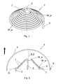
- Fig. 1 shows an example of a heating wire according to the invention in the form of a heating coil.
- the heating wire 1 has a first end 2 and a second end 3.
- the first end 2 runs parallel to the axis of symmetry Z.
- the heating wire 1 describes the shape of a heating coil, wherein the one end 2 is closer to the axis Z than the other end 3.
- the first turn W_e surrounds a larger area than the last turn W_e the winding.
- the heating wire 1 consists of an element. But it is also possible that the heating wire 1 is composed of several elements. In addition, the heating wire is also referred to as a heating element.
- the heating wire 1 is made of a temperature resistant material, e.g. Nickel chrome. However, other material compositions are possible whose temperature resistance is up to 750 ° C.
- the pitch of the individual windings is expediently low, e.g. smaller than the diameter of the heating wire, in order to achieve a good coverage of the carrier body.
- the largest possible length of the wound heating wire is achieved, whereby an effective IR radiation is ensured.
- FIG. 2 shows a schematic representation of a section along the longitudinal axis of a flight destination according to the invention.
- the bow of the destination is shown in FIG.
- the heating element 1 is arranged within the destination 4, wherein the destination 4 is essentially bounded by the fuselage 6 and the IR dome 5.
- the heating element 1 is expediently arranged in the direction of flight (arrow direction) behind the IR dome 5.
- the carrier body 7 may be a carrier body 7, on which the heating element 1 is attached.
- the carrier body 7 expediently has a shape similar to the heating element 1.
- the carrier body 7 may, for example, have the shape of a cone, a truncated cone, a pyramid, a truncated pyramid or a spherical shell.
- the support body 7 may also have a shape of a double cone, a double truncated cone, a double pyramid or a Doppelpyramidenstumpfes, each touching the base surfaces of the cones, cone bottoms, pyramids or truncated pyramids. This ensures IR radiation in a large solid angle range.
- IR emitters emit IR radiation substantially only in the direction of flight or can only illuminate a larger solid angle range with a considerable structural complexity.
- the IR dome 5 is advantageously made of an infrared-transparent material, in particular of zinc sulfide, zinc selenide or magnesium fluoride.
- the infrared-transparent material is expediently chosen so that the transmission of IR radiation in the wavelength range of 3-5 microns and / or 8-12 microns is maximum.
- the IR dome 5 is desirably spherical, i. designed as a spherical shell. This achieves optimum aerodynamics of the destination.
- the transition 8 between the IR dome 5 and the hull 6 is suitably carried out steadily. This ensures that in the flight operation of the destination no turbulence at the contact point 8 between the IR dome 5 and 6 fuselage arise, whereby the air resistance of the destination would be affected.
- the transition 8 is located, seen in the direction of flight, at the same height to the base G of the support body 7. Of course, the transition 8 seen in the direction of flight can be located behind the base G of the support body 2. In the event that the heating element 1 is cantilevered, that is, there is no carrier body present, the transition 8 seen in the direction of flight can be located behind the heating wire 1.
- FIG. 2 shows that one end 2 of the heating element 1 is guided parallel to the axis of symmetry S of the carrier body 7.
- the other end 3 is guided on the edge of the carrier body 7.
- the destination 4 includes a system for temperature control (not shown).
- the control system can change the temperature of the heating element 1 continuously or stepwise. It is expedient to change the temperature during the flight.
- the destination 4 comprises means which can transmit the current temperature of the heating element 1 to a ground station.
- the heating element 1 is electrically operated according to the invention, wherein the power is supplied by entrained generators or batteries.
- the support body 7 is suitably made of a heat-insulating material having a high temperature resistance, e.g. Ceramics.
- the heating element 1 may be applied in a first embodiment directly on the surface of the carrier body 7, e.g. by soldering, welding or gluing. In a second embodiment, however, the heating element may also be mounted at a distance from the carrier body, e.g. by spacers (not shown) between the surface of the carrier body and the heating element.
- the support body 7 may be provided on the surface in the area in which the heating coil 1 covers the support body 7 with a conductive layer 9, e.g. be coated on an Ag layer.
- This layer 9 reflects the IR radiation emitted by the heating element 9, whereby the yield of IR radiation emitted in a solid angle range is improved.
- the heating element 1 can of course also be fastened to the fuselage of the destination 4 in FIG. 2 without the carrier body 7 by means of measures known to a person skilled in the art.
- the exemplary heating element in Fig. 2 may also be rotated 180 °, i. the winding W_e with the smaller area lies in the direction of flight behind the winding W_a with the larger area.
Landscapes
- Engineering & Computer Science (AREA)
- General Engineering & Computer Science (AREA)
- Electromagnetism (AREA)
- Physics & Mathematics (AREA)
- Aviation & Aerospace Engineering (AREA)
- Optics & Photonics (AREA)
- Remote Sensing (AREA)
- Health & Medical Sciences (AREA)
- Radar, Positioning & Navigation (AREA)
- Toxicology (AREA)
- Chemical & Material Sciences (AREA)
- Combustion & Propulsion (AREA)
- Resistance Heating (AREA)
- Transition And Organic Metals Composition Catalysts For Addition Polymerization (AREA)
- Glass Compositions (AREA)
- Seal Device For Vehicle (AREA)
- Medicines That Contain Protein Lipid Enzymes And Other Medicines (AREA)
Abstract
Description
- Die Erfindung betrifft ein Fluggerät zur IR-Flugzieldarstellung nach dem Oberbegriff des Patentanspruchs 1.
- Zum Zwecke der Übung für Boden/Luft- oder Luft/Luft-Waffensysteme mit Infrarot(IR)-Lenkung werden unbemannte Fluggeräte als Flugziele verwendet. Diese Fluggeräte können Schleppflugkörper oder Drohnen sein. Sie sollen möglichst nicht nur die kinetischen Eigenschaften der echten Ziele (z. B. Kampfflugzeuge) simulieren, sondern auch die gleiche Infrarot-(lR)-Abstrahlung aufweisen.
- Aus
DE 40 24 263 C1 sind selbstgetriebene Flugkörper mit pyrotechnisch betriebenen Glühladungen bekannt. Die IR-Abstrahlung wird im Wesentlichen dadurch erzielt, dass die Glühladung eine am Heck des Flugkörpers angeordnete dünne Metallplatte aufheizt. - Bekannt sind Schleppflugkörper und Zieldrohnen, die die gewünschte IR-Abstrahlung mit so genannten Tracking-Flares erzeugen. Diese haben den Nachteil, dass sie im Visuellen sichtbar sind und eine Rauchfahne hinter sich her ziehen. Darüber hinaus ist die spektrale Charakteristik dieser Flares nicht an die Strahlung der echten Ziele angepaßt. Außerdem sorgen Ungleichmäßigkeiten im Abbrand der Flares für unerwünschte Track-Probleme im IR-Suchkopf.
- Aus
EP 0 876 579 B1 undWO 00/29804 - Aus
DE 102 10 433 C1 ist ein Flugziel bekannt, bei welchem eine Fluggasturbine in Flugrichtung vor der Nase des Flugziels angeordnet ist. Die sich im Abgasstrahl der Fluggasturbine befindliche Nase des Flugziels dient als Infrarotstrahler. Ein Nachteil dieser Anordnung ist die schlechte Aerodynamik des Flugziels. - Aus
EP 0 911 601 B1 ist ein Flugziel bekannt, bei welchem in der Nase ein elektrisch betriebener Heizdraht auf einer flachen Radiatorplatte angeordnet ist. Ein Nachteil dieser Anordnung ist, dass eine IR-Abstrahlung nur in Flugrichtung möglich ist. Eine IR-Abstrahlung seitlich zur Flugrichtung ist nur mit großem baulichen Aufwand möglich. - Es ist Aufgabe der Erfindung, ein gattungsgemäßes Flugziel anzugeben, mit welchem eine räumliche IR-Abstrahlung in Flugrichtung und seitlich zur Flugrichtung ohne großen baulichen Aufwand möglich ist.
- Diese Aufgabe löst das Flugziel mit den Merkmalen gemäß Patentanspruch 1. Weitere vorteilhafte Ausgestaltungen der Erfindung sind Gegenstand von Unteransprüchen.
- Erfindungsgemäß ist der Heizdraht in mehreren Windungen W um eine Achse Z aufgewickelt ist, wobei die Wicklung entlang der Achse Z verläuft und die von der ersten Windung W_a eingeschlossene Fläche größer als die von der letzten Windung W_e eingeschlossene Fläche ist. Dadurch wird gewährleistet, dass eine IR-Abstrahlung in einen großen Raumwinkel möglich ist. Außerdem wird der bauliche Aufwand bei optimaler Raumausnutzung gering gehalten.
- Unter einer von einer Windung eingeschlossenen Fläche wird dabei die Fläche verstanden, welche die jeweilige Windung in einer Projektionsfläche senkrecht zur Achse Z einschließt.
- Der erfindungsgemäße Heizdraht bildet somit eine in Richtung der Achse Z gezogene Wicklung. Das Wickelgebilde weist zumindest Abstrahlflächen senkrecht und parallel zur Achse Z auf. Das Wickelgebilde kann aber auch weitere Abstrahlflächen in anderen Raumrichtungen als senkrecht oder parallel zur Achse Z aufweisen.
Die Abstrahlfläche in z.B. Flugrichtung ist definiert durch die Projektion des Wickelgebildes auf eine Ebene senkrecht zur Achse Z, wenn die Achse Z parallel zur Flugachse des Flugziels ausgerichtet ist. Die Abstrahlfläche seitlich zur Flugrichtung ist für den gleichen Fall entsprechend definiert durch eine Projektion auf eine Ebene senkrecht zur Achse Z. - Im einfachsten Fall ist der Heizdraht zu einer konischen Spirale gewickelt. Unter einer konischen Spirale, auch als kegelförmige Raumspirale bezeichnet, versteht man eine Überlagerungskurve von Spirale und Schraube. Eine Spirale ist dabei ein Gebilde in der Ebene, ähnlich den Rillen einer Schallplatte. Eine Schraube ist ein räumliches Gebilde entlang des Mantels eines Zylinders.
- Mit anderen Worten, der Heizdraht ist um die Achse Z gewickelt ist, wobei sich der Durchmesser D der einzelnen Windungen der Wicklung in Längsrichtung der Achse verjüngt. Die Wicklung um die Achse Z erfolgt zweckmäßig symmetrisch. Unter dem Durchmesser D wird hierbei der mittlere Durchmesser der jeweiligen Windung verstanden. Bei einer quadratischen Wicklung, d.h. die Windung bildet die Umrandung eines Quadrats ist der Durchmesser die Diagonale des Quadrats.
- Mit der Erfindung ist somit eine IR-Abstrahlung nicht nur in Flugrichtung des Flugziels, sondern auch seitlich dazu möglich.
- Die Erfindung sowie weitere vorteilhafte Ausführungen der Erfindung werden im Folgenden anhand von Figuren näher erläutert. Es zeigen:
- Fig. 1
- einen erfindungsgemäßen Heizdraht,
- Fig. 2
- einen senkrechten Schnitt entlang der Längsachse eines erfindungsgemäßen Flugziels.
- Fig. 1 zeigt beispielhaft einen erfindungsgemäßen Heizdraht in Form einer Heizspirale. Der Heizdraht 1 weist ein erstes Ende 2 und ein zweites Ende 3 auf. Das erste Ende 2 verläuft dabei parallel zur Symmetrieachse Z.
In diesem Beispiel beschreibt der Heizdraht 1 die Form einer Heizspirale, wobei sich das eine Ende 2 näher an der Achse Z befindet als das andere Ende 3. Die erste Windung W_e umrandet dabei eine größere Fläche als die letzte Windung W_e der Wicklung. - Zweckmäßig besteht der Heizdraht 1 aus einem Element. Es ist aber auch möglich, dass der Heizdraht 1 aus mehreren Elementen aufgebaut ist. Im Weiteren wird der Heizdraht auch als Heizelement bezeichnet.
- Der Heizdraht 1 besteht aus einem temperaturbeständigen Material, z.B. Nickelchrom. Es sind aber auch andere Materialzusammensetzungen möglich, deren Temperaturbeständigkeit bei bis zu 750°C liegt.
- Die Ganghöhe der einzelnen Wicklungen ist zweckmäßig gering, z.B. kleiner als der Durchmesser des Heizdrahtes, um ein gute Überdeckung des Trägerkörpers zu erreichen. Dadurch wird eine möglichst große Länge des gewickelten Heizdrahtes erreicht, wodurch eine effektive IR-Abstrahlung gewährleistet wird.
- Fig. 2 zeigt in einer schematischen Darstellung einen Schnitt entlang der Längsachse eines erfindungsgemäßen Flugziels. Insbesondere ist in Fig. 2 der Bug des Flugziels dargestellt. Das Heizelement 1 ist innerhalb des Flugziels 4 angeordnet, wobei das Flugziel 4 im Wesentlichen vom Rumpf 6 und dem IR-Dom 5 begrenzt ist. Das Heizelement 1 ist zweckmäßig in Flugrichtung (Pfeilrichtung) gesehen hinter dem IR-Dom 5 angeordnet.
- Es kann ein Trägerkörper 7 vorhanden sein, auf welchem das Heizelement 1 befestigt ist. Der Trägerkörper 7 weist zweckmäßig eine dem Heizelement 1 ähnliche Form auf. Der Trägerkörper 7 kann z.B. die Form eines Kegels, eines Kegelstumpfes, einer Pyramide, eines Pyramidenstumpfes oder einer Kugelschale aufweisen. Selbstverständlich kann der Trägerkörper 7 auch eine Form eines Doppelkegels, eines Doppelkegelstumpfes, einer Doppelpyramide oder eines Doppelpyramidenstumpfes aufweisen, wobei sich jeweils die Grundflächen der Kegel, Kegelsümpfe, Pyramiden oder Pyramidenstümpfe berühren. Dadurch wird eine IR-Abstrahlung in einen großen Raumwinkelbereich gewährleistet. Bekannte IR-Strahler emittieren IR-Strahlung im Wesentlichen nur in Flugrichtung bzw. können nur mit einem erheblichen baulichen Aufwand einen größeren Raumwinkelbereich ausleuchten.
Selbstverständlich ist es aber jede andere Form eines Trägerkörpers 7 möglich, bei welcher sich der Trägerkörper 7 zumindest teilweise von einem großen Durchmesser zu einem kleinen Durchmesser hin verjüngt. - Der IR-Dom 5 besteht vorteilhaft aus einem infrarotdurchlässigen Material, insbesondere aus Zinksulfid, Zinkselenid oder Magnesiumfluorid. Das infrarotdurchlässige Material wird zweckmäßig so gewählt, dass die Transmission von IR-Strahlung im Wellenlängenbereich von 3-5 µm und/oder 8-12 µm maximal ist. Der IR-Dom 5 ist zweckmäßig sphärisch, d.h. als Kugelschale ausgeführt. Dadurch wird eine optimale Aerodynamik des Flugziels erreicht.
- Der Übergang 8 zwischen dem IR-Dom 5 und dem Rumpf 6 ist zweckmäßig stetig ausgeführt. Dadurch wird gewährleistet, dass im Flugbetrieb des Flugziels keine Verwirbelungen an der Kontaktstelle 8 zwischen IR-Dom 5 und Rumpf 6 entstehen, wodurch der Luftwiderstand des Flugziels beeinträchtigt werden würde.
Der Übergang 8 befindet sich dabei, in Flugrichtung gesehen, auf gleicher Höhe zur Grundfläche G des Trägerkörpers 7. Selbstverständlich kann sich der Übergang 8 auch in Flugrichtung gesehen hinter der Grundfläche G des Trägerkörpers 2 befinden.
Für den Fall, dass das Heizelement 1 freitragend ist, d.h. es ist kein Trägerkörper vorhanden, kann sich der Übergang 8 in Flugrichtung gesehen hinter dem Heizdraht 1 befinden. - Fig. 2 zeigt, dass das eine Ende 2 des Heizelements 1 parallel zur Symmetrieachse S des Trägerkörpers 7 geführt ist. Das andere Ende 3 ist am Rand des Trägerkörpers 7 geführt.
Zweckmäßig umfasst das Flugziel 4 ein System zur Temperaturregelung (nicht dargestellt). Das Regelungssystem kann dabei die Temperatur des Heizelements 1 kontinuierlich oder stufenweise verändern. Zweckmäßig erfolgt die Veränderung der Temperatur während des Fluges. Hierzu ist es möglich, dass das Flugziel 4 Mittel umfasst, welche die aktuelle Temperatur des Heizelements 1 an eine Bodenstation übermitteln können. - Das Heizelement 1 wird erfindungsgemäß elektrisch betrieben, wobei die Stromversorgung durch mitgeführte Generatoren oder Akkus erfolgt.
- Der Trägerkörper 7 ist zweckmäßig aus einem wärmeisolierenden Material mit einer hohen Temperaturbeständigkeit gefertigt, z.B. Keramik.
- Das Heizelement 1 kann in einer ersten Ausführung direkt auf der Oberfläche des Trägerkörpers 7 aufgebracht sein, z.B. durch Löten, Schweißen oder Kleben. In einer zweiten Ausführungsform kann das Heizelement aber auch beabstandet an dem Trägerkörper angebracht sein, z.B. durch Abstandshalter (nicht dargestellt) zwischen der Oberfläche des Trägerkörpers und dem Heizelement.
- Der Trägerkörper 7 kann auf der Oberfläche in dem Bereich in welchem die Heizspirale 1 den Trägerkörper 7 bedeckt mit einer leitfähigen Schicht 9, z.B. eine Ag-Schicht beschichtet sein. Diese Schicht 9 reflektiert die von dem Heizelement 9 emittierte IR-Strahlung, wodurch die Ausbeute an in einen Raumwinkelbereich emittierter IR-Strahlung verbessert wird.
- Das Heizelement 1 kann in Fig. 2 auch selbstverständlich ohne den Trägerkörper 7 mit einem Fachmann bekannten Maßnahmen am Rumpf des Flugziels 4 befestigt sein. In diesem Fall kann das beispielhafte Heizelement in Fig. 2 auch um 180° gedreht angeordnet sein, d.h. die Windung W_e mit der kleineren Fläche liegt in Flugrichtung gesehen hinter der Windung W_a mit der größeren Fläche.
Claims (9)
- Flugziel mit einem elektrisch betriebenen Heizdraht (1) zur Erzeugung von Infrarotstrahlung
dadurch gekennzeichnet, dass
der Heizdraht (1) in mehreren Windungen W um eine Achse Z aufgewickelt ist, wobei die Wicklung entlang der Achse Z verläuft und die von der ersten Windung W_a eingeschlossene Fläche größer als die von der letzten Windung W_e eingeschlossene Fläche ist. - Flugziel nach Anspruch 1, dadurch gekennzeichnet, dass die Achse Z parallel zur Längsachse S Flugziels (4) ausgerichtet ist.
- Flugziel nach Anspruch 1 oder 2, dadurch gekennzeichnet, dass der Heizdraht (1) auf einen Trägerkörper (7) aufgebracht ist.
- Flugziel nach Anspruch 3, dadurch gekennzeichnet, dass der Trägerköper (7) die Form eines Kegels, eines Kegelstumpfes, einer Pyramide, eines Pyramidenstumpfes oder einer Kugelschale aufweist.
- Flugziel nach einem der vorangehenden Ansprüche 1-4, dadurch gekennzeichnet, dass der Trägerkörper (7) ein Wärmeisolator ist.
- Flugziel nach einem der vorangehenden Ansprüche 3-5, dadurch gekennzeichnet, dass der Trägerkörper (7) mit einer leitfähigen Schicht (9) beschichtet ist.
- Flugziel nach einem der vorangehenden Ansprüche 1-6, dadurch gekennzeichnet, dass das Heizelement (1) hinter einem IR-Dom (5) aus Zinksulfid, Zinkselenid oder Magnesiumfluorid angebracht ist.
- Flugziel nach Anspruch 7, dadurch gekennzeichnet, dass das IR-Dom (5) kugelschalenförmig ist.
- Flugziel nach Anspruch 7 oder 8, dadurch gekennzeichnet, dass der Übergang (8) zwischen dem Rumpf des Flugziels (4) und dem IR-Dom (5) stetig ist.
Applications Claiming Priority (1)
| Application Number | Priority Date | Filing Date | Title |
|---|---|---|---|
| DE102006028596A DE102006028596A1 (de) | 2006-06-22 | 2006-06-22 | Flugziel |
Publications (3)
| Publication Number | Publication Date |
|---|---|
| EP1870663A2 true EP1870663A2 (de) | 2007-12-26 |
| EP1870663A3 EP1870663A3 (de) | 2008-05-28 |
| EP1870663B1 EP1870663B1 (de) | 2009-07-29 |
Family
ID=38477287
Family Applications (1)
| Application Number | Title | Priority Date | Filing Date |
|---|---|---|---|
| EP07011644A Not-in-force EP1870663B1 (de) | 2006-06-22 | 2007-06-14 | Flugziel |
Country Status (4)
| Country | Link |
|---|---|
| EP (1) | EP1870663B1 (de) |
| AT (1) | ATE438073T1 (de) |
| DE (2) | DE102006028596A1 (de) |
| ES (1) | ES2328638T3 (de) |
Cited By (1)
| Publication number | Priority date | Publication date | Assignee | Title |
|---|---|---|---|---|
| CN115493459A (zh) * | 2022-11-21 | 2022-12-20 | 电光(北京)装备技术有限公司 | 一种红外目标模拟外挂吊舱装置 |
Citations (5)
| Publication number | Priority date | Publication date | Assignee | Title |
|---|---|---|---|---|
| DE4024263C1 (en) | 1990-07-31 | 1991-08-22 | Messerschmitt-Boelkow-Blohm Gmbh, 8012 Ottobrunn, De | IR heat radiator for location of self-propelled projectile - is positioned on tail of missile and has rotationally mounted shutter or shield in front of thermal radiator |
| WO2000029804A1 (fr) | 1998-11-13 | 2000-05-25 | Pascal Doe | Cible a rayonnements infrarouges autopropulsee par reaction |
| EP0876579B1 (de) | 1996-01-22 | 2000-11-15 | Meggitt Defence Systems Limited | In der luft fliegendes ziel |
| DE10210433C1 (de) | 2002-03-09 | 2003-08-14 | Dornier Gmbh | Fluggerät zur IR-Flugzieldarstellung |
| EP0911601B1 (de) | 1997-10-22 | 2004-03-24 | Uwins, Stewart Edward | Luftziel |
Family Cites Families (3)
| Publication number | Priority date | Publication date | Assignee | Title |
|---|---|---|---|---|
| US3086202A (en) * | 1956-10-22 | 1963-04-16 | Del Mar Eng Lab | Infrared emitting tow target |
| JPH02126100A (ja) * | 1988-11-07 | 1990-05-15 | Mitsubishi Electric Corp | 標的 |
| JP2865207B2 (ja) * | 1989-02-18 | 1999-03-08 | 松下電工株式会社 | 毛髪乾燥器 |
-
2006
- 2006-06-22 DE DE102006028596A patent/DE102006028596A1/de not_active Withdrawn
-
2007
- 2007-06-14 DE DE502007001164T patent/DE502007001164D1/de active Active
- 2007-06-14 EP EP07011644A patent/EP1870663B1/de not_active Not-in-force
- 2007-06-14 AT AT07011644T patent/ATE438073T1/de active
- 2007-06-14 ES ES07011644T patent/ES2328638T3/es active Active
Patent Citations (5)
| Publication number | Priority date | Publication date | Assignee | Title |
|---|---|---|---|---|
| DE4024263C1 (en) | 1990-07-31 | 1991-08-22 | Messerschmitt-Boelkow-Blohm Gmbh, 8012 Ottobrunn, De | IR heat radiator for location of self-propelled projectile - is positioned on tail of missile and has rotationally mounted shutter or shield in front of thermal radiator |
| EP0876579B1 (de) | 1996-01-22 | 2000-11-15 | Meggitt Defence Systems Limited | In der luft fliegendes ziel |
| EP0911601B1 (de) | 1997-10-22 | 2004-03-24 | Uwins, Stewart Edward | Luftziel |
| WO2000029804A1 (fr) | 1998-11-13 | 2000-05-25 | Pascal Doe | Cible a rayonnements infrarouges autopropulsee par reaction |
| DE10210433C1 (de) | 2002-03-09 | 2003-08-14 | Dornier Gmbh | Fluggerät zur IR-Flugzieldarstellung |
Cited By (1)
| Publication number | Priority date | Publication date | Assignee | Title |
|---|---|---|---|---|
| CN115493459A (zh) * | 2022-11-21 | 2022-12-20 | 电光(北京)装备技术有限公司 | 一种红外目标模拟外挂吊舱装置 |
Also Published As
| Publication number | Publication date |
|---|---|
| ATE438073T1 (de) | 2009-08-15 |
| ES2328638T3 (es) | 2009-11-16 |
| EP1870663A3 (de) | 2008-05-28 |
| EP1870663B1 (de) | 2009-07-29 |
| DE502007001164D1 (de) | 2009-09-10 |
| DE102006028596A1 (de) | 2007-12-27 |
Similar Documents
| Publication | Publication Date | Title |
|---|---|---|
| EP1813907B1 (de) | Flugkörper für den Überschallbereich | |
| EP2754989B1 (de) | Vorrichtung und Verfahren zum Richten eines Raketenabschussbehälters | |
| DE4238038C1 (de) | Verfahren zum Bereitstellen eines Scheinzielkörpers | |
| DE102008022289B4 (de) | Flugkörper | |
| DE2150517A1 (de) | Zielflugkoerper,insbesondere fuer das Training von Luftabwehrtruppen | |
| EP2482025B1 (de) | Verfahren und Vorrichtung zum Abwehren eines angreifenden Flugkörpers | |
| EP1870663B1 (de) | Flugziel | |
| DE1958355A1 (de) | Flugkoerpersystem | |
| DE2141744C3 (de) | Flugkörper mit Schubvektor- und aerodynamischer Steuerung | |
| DE60028303T2 (de) | Strahler von Infrarotstrahlung im Band III und Verbundmaterial, welches die Emission von solcher Strahlung erlaubt | |
| EP1342978B1 (de) | Fluggerät zur Flugzieldarstellung | |
| EP3118567B1 (de) | Verfahren zum schützen eines fahrzeugs vor einem angriff durch einen laserstrahl | |
| DE965185C (de) | Aerodynamisch stabilisierter, unsteuerbarer Flugkoerper | |
| DE10061772C1 (de) | Stabilisierungseinheit für einen Schleppkörper | |
| DE3426990C2 (de) | Radarschutz an einem Fluggerät | |
| EP0795759B1 (de) | Flugkörper zur Entdeckung und Bekämpfung feindlicher Hubschrauber | |
| DE19605337C2 (de) | Verfahren zur Veränderung der Infrarot-Signatur eines Flugzeuges | |
| EP3699544A1 (de) | Dircm mit doppelverfolgung eines ziels | |
| DE102006015952A1 (de) | Flugkörper für den Überschallbereich | |
| DE69902303T2 (de) | Vorrichtung zur Aussendung von Infrarotstrahlen | |
| DE3108283A1 (de) | "lenkflugkoerper" | |
| DE1472496C1 (de) | Vorrichtung zur Erzeugung und gerichteten Aussendung von elektromagnetischer Strahlung,insbesondere im Wellenlaengenbereich ueber 1,8 mu | |
| DE102009035355B4 (de) | Umschaltbare Wirkladung für einen Gefechtskopf | |
| EP3118566B1 (de) | Verfahren zum schützen eines fahrzeugs vor einem angriff durch einen laserstrahl | |
| EP3118565A1 (de) | Verfahren zum schützen eines fahrzeugs vor einem angriff durch einen laserstrahl |
Legal Events
| Date | Code | Title | Description |
|---|---|---|---|
| PUAI | Public reference made under article 153(3) epc to a published international application that has entered the european phase |
Free format text: ORIGINAL CODE: 0009012 |
|
| AK | Designated contracting states |
Kind code of ref document: A2 Designated state(s): AT BE BG CH CY CZ DE DK EE ES FI FR GB GR HU IE IS IT LI LT LU LV MC MT NL PL PT RO SE SI SK TR |
|
| AX | Request for extension of the european patent |
Extension state: AL BA HR MK YU |
|
| PUAL | Search report despatched |
Free format text: ORIGINAL CODE: 0009013 |
|
| AK | Designated contracting states |
Kind code of ref document: A3 Designated state(s): AT BE BG CH CY CZ DE DK EE ES FI FR GB GR HU IE IS IT LI LT LU LV MC MT NL PL PT RO SE SI SK TR |
|
| AX | Request for extension of the european patent |
Extension state: AL BA HR MK RS |
|
| RIC1 | Information provided on ipc code assigned before grant |
Ipc: F41J 2/02 20060101AFI20070921BHEP Ipc: F41J 9/10 20060101ALN20070922BHEP Ipc: F42B 12/38 20060101ALI20080418BHEP Ipc: F41J 9/08 20060101ALN20070922BHEP |
|
| 17P | Request for examination filed |
Effective date: 20080619 |
|
| 17Q | First examination report despatched |
Effective date: 20080730 |
|
| AKX | Designation fees paid |
Designated state(s): AT BE BG CH CY CZ DE DK EE ES FI FR GB GR HU IE IS IT LI LT LU LV MC MT NL PL PT RO SE SI SK TR |
|
| GRAP | Despatch of communication of intention to grant a patent |
Free format text: ORIGINAL CODE: EPIDOSNIGR1 |
|
| GRAS | Grant fee paid |
Free format text: ORIGINAL CODE: EPIDOSNIGR3 |
|
| GRAA | (expected) grant |
Free format text: ORIGINAL CODE: 0009210 |
|
| AK | Designated contracting states |
Kind code of ref document: B1 Designated state(s): AT BE BG CH CY CZ DE DK EE ES FI FR GB GR HU IE IS IT LI LT LU LV MC MT NL PL PT RO SE SI SK TR |
|
| REG | Reference to a national code |
Ref country code: GB Ref legal event code: FG4D Free format text: NOT ENGLISH |
|
| REG | Reference to a national code |
Ref country code: CH Ref legal event code: EP |
|
| REG | Reference to a national code |
Ref country code: IE Ref legal event code: FG4D |
|
| REF | Corresponds to: |
Ref document number: 502007001164 Country of ref document: DE Date of ref document: 20090910 Kind code of ref document: P |
|
| REG | Reference to a national code |
Ref country code: ES Ref legal event code: FG2A Ref document number: 2328638 Country of ref document: ES Kind code of ref document: T3 |
|
| REG | Reference to a national code |
Ref country code: GR Ref legal event code: EP Ref document number: 20090402636 Country of ref document: GR |
|
| NLV1 | Nl: lapsed or annulled due to failure to fulfill the requirements of art. 29p and 29m of the patents act | ||
| PG25 | Lapsed in a contracting state [announced via postgrant information from national office to epo] |
Ref country code: LT Free format text: LAPSE BECAUSE OF FAILURE TO SUBMIT A TRANSLATION OF THE DESCRIPTION OR TO PAY THE FEE WITHIN THE PRESCRIBED TIME-LIMIT Effective date: 20090729 Ref country code: SE Free format text: LAPSE BECAUSE OF FAILURE TO SUBMIT A TRANSLATION OF THE DESCRIPTION OR TO PAY THE FEE WITHIN THE PRESCRIBED TIME-LIMIT Effective date: 20090729 Ref country code: IS Free format text: LAPSE BECAUSE OF FAILURE TO SUBMIT A TRANSLATION OF THE DESCRIPTION OR TO PAY THE FEE WITHIN THE PRESCRIBED TIME-LIMIT Effective date: 20091129 Ref country code: FI Free format text: LAPSE BECAUSE OF FAILURE TO SUBMIT A TRANSLATION OF THE DESCRIPTION OR TO PAY THE FEE WITHIN THE PRESCRIBED TIME-LIMIT Effective date: 20090729 |
|
| PG25 | Lapsed in a contracting state [announced via postgrant information from national office to epo] |
Ref country code: SI Free format text: LAPSE BECAUSE OF FAILURE TO SUBMIT A TRANSLATION OF THE DESCRIPTION OR TO PAY THE FEE WITHIN THE PRESCRIBED TIME-LIMIT Effective date: 20090729 Ref country code: NL Free format text: LAPSE BECAUSE OF FAILURE TO SUBMIT A TRANSLATION OF THE DESCRIPTION OR TO PAY THE FEE WITHIN THE PRESCRIBED TIME-LIMIT Effective date: 20090729 Ref country code: PL Free format text: LAPSE BECAUSE OF FAILURE TO SUBMIT A TRANSLATION OF THE DESCRIPTION OR TO PAY THE FEE WITHIN THE PRESCRIBED TIME-LIMIT Effective date: 20090729 Ref country code: LV Free format text: LAPSE BECAUSE OF FAILURE TO SUBMIT A TRANSLATION OF THE DESCRIPTION OR TO PAY THE FEE WITHIN THE PRESCRIBED TIME-LIMIT Effective date: 20090729 |
|
| REG | Reference to a national code |
Ref country code: IE Ref legal event code: FD4D |
|
| PG25 | Lapsed in a contracting state [announced via postgrant information from national office to epo] |
Ref country code: BG Free format text: LAPSE BECAUSE OF FAILURE TO SUBMIT A TRANSLATION OF THE DESCRIPTION OR TO PAY THE FEE WITHIN THE PRESCRIBED TIME-LIMIT Effective date: 20091029 Ref country code: PT Free format text: LAPSE BECAUSE OF FAILURE TO SUBMIT A TRANSLATION OF THE DESCRIPTION OR TO PAY THE FEE WITHIN THE PRESCRIBED TIME-LIMIT Effective date: 20091129 |
|
| PG25 | Lapsed in a contracting state [announced via postgrant information from national office to epo] |
Ref country code: IE Free format text: LAPSE BECAUSE OF FAILURE TO SUBMIT A TRANSLATION OF THE DESCRIPTION OR TO PAY THE FEE WITHIN THE PRESCRIBED TIME-LIMIT Effective date: 20090729 Ref country code: RO Free format text: LAPSE BECAUSE OF FAILURE TO SUBMIT A TRANSLATION OF THE DESCRIPTION OR TO PAY THE FEE WITHIN THE PRESCRIBED TIME-LIMIT Effective date: 20090729 Ref country code: CZ Free format text: LAPSE BECAUSE OF FAILURE TO SUBMIT A TRANSLATION OF THE DESCRIPTION OR TO PAY THE FEE WITHIN THE PRESCRIBED TIME-LIMIT Effective date: 20090729 Ref country code: DK Free format text: LAPSE BECAUSE OF FAILURE TO SUBMIT A TRANSLATION OF THE DESCRIPTION OR TO PAY THE FEE WITHIN THE PRESCRIBED TIME-LIMIT Effective date: 20090729 Ref country code: EE Free format text: LAPSE BECAUSE OF FAILURE TO SUBMIT A TRANSLATION OF THE DESCRIPTION OR TO PAY THE FEE WITHIN THE PRESCRIBED TIME-LIMIT Effective date: 20090729 |
|
| PG25 | Lapsed in a contracting state [announced via postgrant information from national office to epo] |
Ref country code: SK Free format text: LAPSE BECAUSE OF FAILURE TO SUBMIT A TRANSLATION OF THE DESCRIPTION OR TO PAY THE FEE WITHIN THE PRESCRIBED TIME-LIMIT Effective date: 20090729 |
|
| PLBE | No opposition filed within time limit |
Free format text: ORIGINAL CODE: 0009261 |
|
| STAA | Information on the status of an ep patent application or granted ep patent |
Free format text: STATUS: NO OPPOSITION FILED WITHIN TIME LIMIT |
|
| 26N | No opposition filed |
Effective date: 20100503 |
|
| BERE | Be: lapsed |
Owner name: EADS DEUTSCHLAND G.M.B.H. Effective date: 20100630 |
|
| PG25 | Lapsed in a contracting state [announced via postgrant information from national office to epo] |
Ref country code: MC Free format text: LAPSE BECAUSE OF NON-PAYMENT OF DUE FEES Effective date: 20100630 |
|
| PG25 | Lapsed in a contracting state [announced via postgrant information from national office to epo] |
Ref country code: IT Free format text: LAPSE BECAUSE OF FAILURE TO SUBMIT A TRANSLATION OF THE DESCRIPTION OR TO PAY THE FEE WITHIN THE PRESCRIBED TIME-LIMIT Effective date: 20090729 |
|
| PG25 | Lapsed in a contracting state [announced via postgrant information from national office to epo] |
Ref country code: MT Free format text: LAPSE BECAUSE OF FAILURE TO SUBMIT A TRANSLATION OF THE DESCRIPTION OR TO PAY THE FEE WITHIN THE PRESCRIBED TIME-LIMIT Effective date: 20090729 |
|
| PG25 | Lapsed in a contracting state [announced via postgrant information from national office to epo] |
Ref country code: BE Free format text: LAPSE BECAUSE OF NON-PAYMENT OF DUE FEES Effective date: 20100630 |
|
| REG | Reference to a national code |
Ref country code: CH Ref legal event code: PL |
|
| PG25 | Lapsed in a contracting state [announced via postgrant information from national office to epo] |
Ref country code: LI Free format text: LAPSE BECAUSE OF NON-PAYMENT OF DUE FEES Effective date: 20110630 Ref country code: CH Free format text: LAPSE BECAUSE OF NON-PAYMENT OF DUE FEES Effective date: 20110630 |
|
| PG25 | Lapsed in a contracting state [announced via postgrant information from national office to epo] |
Ref country code: CY Free format text: LAPSE BECAUSE OF FAILURE TO SUBMIT A TRANSLATION OF THE DESCRIPTION OR TO PAY THE FEE WITHIN THE PRESCRIBED TIME-LIMIT Effective date: 20090729 |
|
| PG25 | Lapsed in a contracting state [announced via postgrant information from national office to epo] |
Ref country code: HU Free format text: LAPSE BECAUSE OF FAILURE TO SUBMIT A TRANSLATION OF THE DESCRIPTION OR TO PAY THE FEE WITHIN THE PRESCRIBED TIME-LIMIT Effective date: 20100130 Ref country code: LU Free format text: LAPSE BECAUSE OF NON-PAYMENT OF DUE FEES Effective date: 20100614 |
|
| PG25 | Lapsed in a contracting state [announced via postgrant information from national office to epo] |
Ref country code: TR Free format text: LAPSE BECAUSE OF FAILURE TO SUBMIT A TRANSLATION OF THE DESCRIPTION OR TO PAY THE FEE WITHIN THE PRESCRIBED TIME-LIMIT Effective date: 20090729 |
|
| REG | Reference to a national code |
Ref country code: AT Ref legal event code: MM01 Ref document number: 438073 Country of ref document: AT Kind code of ref document: T Effective date: 20120614 |
|
| PG25 | Lapsed in a contracting state [announced via postgrant information from national office to epo] |
Ref country code: AT Free format text: LAPSE BECAUSE OF NON-PAYMENT OF DUE FEES Effective date: 20120614 |
|
| REG | Reference to a national code |
Ref country code: DE Ref legal event code: R081 Ref document number: 502007001164 Country of ref document: DE Owner name: AIRBUS DEFENCE AND SPACE GMBH, DE Free format text: FORMER OWNER: EADS DEUTSCHLAND GMBH, 85521 OTTOBRUNN, DE Effective date: 20140916 |
|
| REG | Reference to a national code |
Ref country code: FR Ref legal event code: PLFP Year of fee payment: 9 |
|
| REG | Reference to a national code |
Ref country code: FR Ref legal event code: PLFP Year of fee payment: 10 |
|
| REG | Reference to a national code |
Ref country code: FR Ref legal event code: PLFP Year of fee payment: 11 |
|
| REG | Reference to a national code |
Ref country code: FR Ref legal event code: PLFP Year of fee payment: 12 |
|
| REG | Reference to a national code |
Ref country code: FR Ref legal event code: CA Effective date: 20180605 Ref country code: FR Ref legal event code: CD Owner name: EADS DEUTSCHLAND GMBH, DE Effective date: 20180605 |
|
| PGFP | Annual fee paid to national office [announced via postgrant information from national office to epo] |
Ref country code: FR Payment date: 20230627 Year of fee payment: 17 Ref country code: DE Payment date: 20230620 Year of fee payment: 17 |
|
| PGFP | Annual fee paid to national office [announced via postgrant information from national office to epo] |
Ref country code: GR Payment date: 20230621 Year of fee payment: 17 |
|
| PGFP | Annual fee paid to national office [announced via postgrant information from national office to epo] |
Ref country code: GB Payment date: 20230620 Year of fee payment: 17 Ref country code: ES Payment date: 20230828 Year of fee payment: 17 |
|
| REG | Reference to a national code |
Ref country code: DE Ref legal event code: R119 Ref document number: 502007001164 Country of ref document: DE |
|
| GBPC | Gb: european patent ceased through non-payment of renewal fee |
Effective date: 20240614 |
|
| PG25 | Lapsed in a contracting state [announced via postgrant information from national office to epo] |
Ref country code: DE Free format text: LAPSE BECAUSE OF NON-PAYMENT OF DUE FEES Effective date: 20250101 |
|
| PG25 | Lapsed in a contracting state [announced via postgrant information from national office to epo] |
Ref country code: GR Free format text: LAPSE BECAUSE OF NON-PAYMENT OF DUE FEES Effective date: 20250108 |
|
| PG25 | Lapsed in a contracting state [announced via postgrant information from national office to epo] |
Ref country code: FR Free format text: LAPSE BECAUSE OF NON-PAYMENT OF DUE FEES Effective date: 20240630 |
|
| PG25 | Lapsed in a contracting state [announced via postgrant information from national office to epo] |
Ref country code: GB Free format text: LAPSE BECAUSE OF NON-PAYMENT OF DUE FEES Effective date: 20240614 |
|
| REG | Reference to a national code |
Ref country code: ES Ref legal event code: FD2A Effective date: 20250728 |
|
| PG25 | Lapsed in a contracting state [announced via postgrant information from national office to epo] |
Ref country code: ES Free format text: LAPSE BECAUSE OF NON-PAYMENT OF DUE FEES Effective date: 20240615 |