EP1870600A1 - Palier pou aube de stator à calage variable - Google Patents
Palier pou aube de stator à calage variable Download PDFInfo
- Publication number
- EP1870600A1 EP1870600A1 EP07110629A EP07110629A EP1870600A1 EP 1870600 A1 EP1870600 A1 EP 1870600A1 EP 07110629 A EP07110629 A EP 07110629A EP 07110629 A EP07110629 A EP 07110629A EP 1870600 A1 EP1870600 A1 EP 1870600A1
- Authority
- EP
- European Patent Office
- Prior art keywords
- pivot
- bearing
- turbomachine
- blade
- bore
- Prior art date
- Legal status (The legal status is an assumption and is not a legal conclusion. Google has not performed a legal analysis and makes no representation as to the accuracy of the status listed.)
- Granted
Links
Images


Classifications
-
- F—MECHANICAL ENGINEERING; LIGHTING; HEATING; WEAPONS; BLASTING
- F04—POSITIVE - DISPLACEMENT MACHINES FOR LIQUIDS; PUMPS FOR LIQUIDS OR ELASTIC FLUIDS
- F04D—NON-POSITIVE-DISPLACEMENT PUMPS
- F04D29/00—Details, component parts, or accessories
- F04D29/40—Casings; Connections of working fluid
- F04D29/52—Casings; Connections of working fluid for axial pumps
- F04D29/54—Fluid-guiding means, e.g. diffusers
- F04D29/56—Fluid-guiding means, e.g. diffusers adjustable
- F04D29/563—Fluid-guiding means, e.g. diffusers adjustable specially adapted for elastic fluid pumps
-
- F—MECHANICAL ENGINEERING; LIGHTING; HEATING; WEAPONS; BLASTING
- F01—MACHINES OR ENGINES IN GENERAL; ENGINE PLANTS IN GENERAL; STEAM ENGINES
- F01D—NON-POSITIVE DISPLACEMENT MACHINES OR ENGINES, e.g. STEAM TURBINES
- F01D17/00—Regulating or controlling by varying flow
- F01D17/10—Final actuators
- F01D17/12—Final actuators arranged in stator parts
- F01D17/14—Final actuators arranged in stator parts varying effective cross-sectional area of nozzles or guide conduits
- F01D17/16—Final actuators arranged in stator parts varying effective cross-sectional area of nozzles or guide conduits by means of nozzle vanes
- F01D17/162—Final actuators arranged in stator parts varying effective cross-sectional area of nozzles or guide conduits by means of nozzle vanes for axial flow, i.e. the vanes turning around axes which are essentially perpendicular to the rotor centre line
-
- F—MECHANICAL ENGINEERING; LIGHTING; HEATING; WEAPONS; BLASTING
- F04—POSITIVE - DISPLACEMENT MACHINES FOR LIQUIDS; PUMPS FOR LIQUIDS OR ELASTIC FLUIDS
- F04D—NON-POSITIVE-DISPLACEMENT PUMPS
- F04D29/00—Details, component parts, or accessories
- F04D29/05—Shafts or bearings, or assemblies thereof, specially adapted for elastic fluid pumps
- F04D29/056—Bearings
- F04D29/057—Bearings hydrostatic; hydrodynamic
-
- F—MECHANICAL ENGINEERING; LIGHTING; HEATING; WEAPONS; BLASTING
- F16—ENGINEERING ELEMENTS AND UNITS; GENERAL MEASURES FOR PRODUCING AND MAINTAINING EFFECTIVE FUNCTIONING OF MACHINES OR INSTALLATIONS; THERMAL INSULATION IN GENERAL
- F16F—SPRINGS; SHOCK-ABSORBERS; MEANS FOR DAMPING VIBRATION
- F16F1/00—Springs
- F16F1/36—Springs made of rubber or other material having high internal friction, e.g. thermoplastic elastomers
- F16F1/38—Springs made of rubber or other material having high internal friction, e.g. thermoplastic elastomers with a sleeve of elastic material between a rigid outer sleeve and a rigid inner sleeve or pin, i.e. bushing-type
- F16F1/3863—Springs made of rubber or other material having high internal friction, e.g. thermoplastic elastomers with a sleeve of elastic material between a rigid outer sleeve and a rigid inner sleeve or pin, i.e. bushing-type characterised by the rigid sleeves or pin, e.g. of non-circular cross-section
-
- F—MECHANICAL ENGINEERING; LIGHTING; HEATING; WEAPONS; BLASTING
- F05—INDEXING SCHEMES RELATING TO ENGINES OR PUMPS IN VARIOUS SUBCLASSES OF CLASSES F01-F04
- F05D—INDEXING SCHEME FOR ASPECTS RELATING TO NON-POSITIVE-DISPLACEMENT MACHINES OR ENGINES, GAS-TURBINES OR JET-PROPULSION PLANTS
- F05D2300/00—Materials; Properties thereof
- F05D2300/40—Organic materials
- F05D2300/43—Synthetic polymers, e.g. plastics; Rubber
- F05D2300/431—Rubber
-
- F—MECHANICAL ENGINEERING; LIGHTING; HEATING; WEAPONS; BLASTING
- F05—INDEXING SCHEMES RELATING TO ENGINES OR PUMPS IN VARIOUS SUBCLASSES OF CLASSES F01-F04
- F05D—INDEXING SCHEME FOR ASPECTS RELATING TO NON-POSITIVE-DISPLACEMENT MACHINES OR ENGINES, GAS-TURBINES OR JET-PROPULSION PLANTS
- F05D2300/00—Materials; Properties thereof
- F05D2300/50—Intrinsic material properties or characteristics
- F05D2300/501—Elasticity
Definitions
- the present invention relates to the field of turbomachines such as an axial compressor of gas turbine engine, and aims in particular stator vanes with variable pitch of the machine.
- FIG. 1 schematically shows a blade 1 of variable-pitch rectifier mounted in the casing 3 of the machine.
- the stator blade comprises a blade 12, a plate or platform 13 and a pivot rod 14 at one end.
- the pivot 14 is housed in a bore or radial orifice formed in the wall of the casing 3 by means of different bearings. Dawn is held only by this extremity.
- the other end retains a floating annular element 16 in which it is pivotally mounted by a second pivot 17.
- the ring is provided with sealing means for the portion of the rotor 18 which is adjacent thereto.
- the pivot 14 journals in the corresponding bore of the housing through bearings, for example a low bearing 4 on the side of the platform.
- the platform 13 is housed in a cavity in the form of countersink machined in the wall of this housing.
- the housing wall is in radial contact with the platform 13 either directly or via a bushing or washer.
- the upper part of the pivot 14 is retained in a high bearing 5.
- the bearings 4 and 5 consist for example of bushings housed in the bore of the housing with an inner ring forming a friction surface with the rod 14 forming a pivot. A friction ring can also be hooped on the rod 14.
- the opposite face of the platform 13 with respect to the bearing 4 forms the base of the blade and is swept by the gases set in motion by the compressor.
- This face of the plate is shaped to ensure the continuity of the vein formed by the housing.
- a nut 15 keepss the blade in its housing and a lever actuated by appropriate control members, controls the rotation of the blade around the axis XX of the rod to put it in the required position relative to the direction of the gas flow.
- the relative movements result from the sliding of the surfaces in contact with each other.
- the blade 12 In the case of an axial compressor of gas turbine engine or of a single axial compressor of air or other gas, such as blast furnace or natural gas, the blade 12 is subjected over its entire length to the aerodynamic forces and pressure generated by the gas flow.
- the component of these forces oriented perpendicular to the chord in the direction intrados towards extrados, passing generally by the axis of the pivot is the most important. It is also noted that in cases of major robberies the component can deviate from this axis.
- the blade is also subjected to axial forces of static pressure directed upstream due to the pressure difference between the downstream and the upstream. The resulting force is illustrated by the arrow F in the figure. It follows the application of a moment associated with the pitch rotation around the axis XX on an amplitude that can reach and exceed 40 degrees.
- the applicant has set as an objective the establishment of means to support the variable-pitch vanes of the type presented above no or less subject to wear.
- variable-speed turbomachine rectifier blade pivot bearing mounted in a bore of the turbomachine casing, characterized in that it comprises an inner sleeve integral with said axis. and an outer bushing secured to said bore, an elastomeric material being interposed between the inner bushing and the outer bushing allowing pivoting of the blade about its axis and the absorption at least partly of the bending of the pivot perpendicular to the axis .
- the socket structure according to the invention also has the advantage of having, if necessary, a damping effect. It helps dissipate energy vibratory when the straightener is subjected to aerodynamic excitations. The vibratory modes of the rectifiers are lessened.
- the inner sleeve is subdivided into two cylindrical elements at least in the extension of one another. This allows the inner bushing to adapt to the deformations of the pivot.
- the number of elements constituting the inner sleeve can be increased so as to provide the most faithful adaptation possible.
- the various elements are separated by an annular layer of elastomer so as to improve the seal along the pivot.
- Such a bearing arrangement is advantageous when it is applied to the bearing mounted under the lever for actuating the blade.
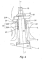
- the pivot is supported by a bearing 4 on the side of the platform 13 - the blade is not shown - and by a bearing 20 on the side of the rod 19.
- the invention relates to the bearing 20.
- This is composed of an outer sleeve 21 hooped in the bore of the housing 3.
- This outer sleeve is cylindrical with a flange 21A, transverse, resting on the outer edge of the bore. This flange is interposed between the housing and the rod 19.
- a space is provided between the two sockets which is occupied by an elastomeric material.
- it adheres to the two sockets 21 and 22 and occupies the space between the two cylindrical elements 22A and 22B.
- Figure 3 shows in more detail the arrangement of the sockets between them.
- the elastomeric material is selected so as to deform, to allow a rotational movement of a socket relative to the other by an angle in one direction and the other, corresponding to the adjustment of the required setting of the rectifier.
- the thickness of the elastomeric material is also one of the parameters that must be taken into account in the development of the bearing.
- the elastomer participates in sealing along the surface of the pivot. It is observed that only two elements are represented but the inner sleeve can be composed of a plurality of elements.
- the elastomeric material accompanies the rotational movements of the pivot about the axis XX while ensuring a good seal but also absorbs the forces applied to the pivot in the transverse direction and distributes them over a larger area than if the contact between the moving parts were smooth and hard.
- the bearing according to the invention is shown applied to the external support of the pivot, but it can be used in other zones to the extent that the environment, in particular thermal, allows it.
Landscapes
- Engineering & Computer Science (AREA)
- General Engineering & Computer Science (AREA)
- Mechanical Engineering (AREA)
- Physics & Mathematics (AREA)
- Fluid Mechanics (AREA)
- Structures Of Non-Positive Displacement Pumps (AREA)
- Support Of The Bearing (AREA)
- Control Of Turbines (AREA)
- Turbine Rotor Nozzle Sealing (AREA)
Abstract
Description
- La présente invention se rapporte au domaine des turbomachines tel qu'un compresseur axial de moteur à turbine à gaz, et vise en particulier les aubes de stator à calage variable de la machine.
- Un système articulé, comme les aubes de redresseur à calage variable d'un compresseur de moteur à turbine à gaz, comprend des pièces en mouvement relatif les unes par rapport aux autres. Sur la figure 1, on a représenté de façon schématique, une aube 1 de redresseur à calage variable montée dans le carter 3 de la machine. L'aube statorique comprend une pale 12, une platine ou plateforme 13 et une tige formant pivot 14 à une extrémité. Le pivot 14 est logé dans un alésage ou orifice radial ménagé dans la paroi du carter 3 par l'intermédiaire de différents paliers. L'aube n'est tenue que par cette extrémité. L'autre extrémité retient un élément annulaire flottant 16 dans lequel il est monté pivotant par un second pivot 17. L'anneau est pourvu de moyens d'étanchéité pour la partie du rotor 18 qui lui est adjacente.
- Le pivot 14 tourillonne dans l'alésage correspondant du carter par l'intermédiaire de paliers, par exemple un palier bas 4 du côté de la plateforme. La plateforme 13 est logée dans une cavité en forme de lamage usiné dans la paroi de ce carter. La paroi du carter est en contact radial avec la plateforme 13 soit directement soit par l'intermédiaire d'une douille ou rondelle. La partie haute du pivot 14 est retenue dans un palier haut 5. Les paliers 4 et 5 sont par exemple constitués de douilles logées dans l'alésage du carter avec une bague interne formant surface de frottement avec la tige 14 formant pivot. Une bague de frottement peut également être frettée sur la tige 14.
- La face opposée de la plateforme 13 par rapport au palier 4 forme la base de la pale et est balayée par les gaz mis en mouvement par le compresseur. Cette face de la platine est conformée de manière à assurer la continuité de la veine formée par le carter. Un écrou 15' maintient l'aube dans son logement et un levier actionné par des organes de commande appropriés, commande la rotation de l'aube autour de l'axe XX de la tige pour mettre celle-ci dans la position requise par rapport à la direction du flux gazeux. Les mouvements relatifs résultent du glissement des surfaces en contact entre elles.
- Dans le cas d'un compresseur axial de moteur à turbine à gaz ou bien d'un compresseur axial seul d'air ou autre gaz, tel que de haut fourneau ou gaz naturel, la pale 12 est soumise sur toute sa longueur aux efforts aérodynamiques et de pression engendrés par le flux gazeux. La composante de ces efforts orientée perpendiculairement à la corde dans le sens intrados vers extrados, en passant généralement par l'axe du pivot est la plus importante. On note aussi que dans les cas de braquages importants la composante peut s'écarter de cet axe. La pale est soumise aussi à des efforts axiaux de pression statique dirigés vers l'amont en raison de la différence de pression entre l'aval et l'amont. La force résultante est illustrée par la flèche F sur la figure. Il s'ensuit l'application d'un moment qui associé à la rotation de calage autour de l'axe XX sur une amplitude qui peut atteindre et dépasser 40 degrés.
- Comme on l'a mentionné plus haut les douilles que l'on monte sous les leviers du système de calage variable ne permettent aucun mouvement autre que la rotation autour de l'axe du pivot. On constate toutefois qu'en raison des efforts transversaux et de la flexion des redresseurs les douilles de l'art antérieur présentent une usure irrégulière. Une telle usure est dommageable au bon fonctionnement du dispositif de calage variable.
- Le déposant s'est fixé comme objectif la mise en place de moyens pour supporter les aubes à calage variable du type présenté ci-dessus non ou moins sujets à usure.
- Conformément à l'invention, on parvient à cet objectif avec un palier pour pivot d'aube de redresseur à calage variable de turbomachine monté dans un alésage du carter de la turbomachine, caractérisé par le fait qu'il comprend une douille interne solidaire dudit axe et une douille externe solidaire dudit alésage, un matériau élastomère étant interposé entre la douille interne et la douille externe permettant le pivotement de l'aube autour de son axe et l'absorption au moins en partie de la flexion du pivot perpendiculairement à l'axe.
- Grâce à cette disposition le palier fonctionne comme une rotule et permet d'augmenter la surface effective entre le pivot et la douille externe. L'usure des pièces s'en trouve ainsi réduite.
- La structure de douille selon l'invention a également comme avantage d'avoir, le cas échéant, un effet amortisseur. Il permet de dissiper l'énergie vibratoire lorsque le redresseur est soumis à des excitations aérodynamiques. Les modes vibratoires des redresseurs s'en trouvent amoindris.
- Avantageusement la douille interne est subdivisée en deux éléments cylindriques au moins dans le prolongement l'un de l'autre. Cela permet à la douille interne de s'adapter aux déformations du pivot. On peut augmenter le nombre d'éléments constituant la douille interne de façon à procurer une adaptation la plus fidèle possible.
- Plus particulièrement, les différents éléments sont séparés par une couche annulaire d'élastomère de façon à améliorer l'étanchéité le long du pivot.
- Un tel agencement de palier est avantageux lorsqu'il est appliqué au palier monté sous le levier d'actionnement de l'aubage.
- On décrit maintenant l'invention plus en détail en référence aux dessins annexés sur lesquels
- La figure 1 montre vue en coupe de profil une aube de redresseur à calage variable montée dans un alésage du carter d'une turbomachine, selon l'art antérieur ;
- La figure 2 montre vue en coupe de profil et agrandie par rapport à la première la partie du pivot du côté de la biellette de commande avec le montage selon l'invention ;
- La figure 3 montre en demi coupe et en perspective le palier selon l'invention, seul.
- En référence à la figure 2, on voit le pivot 14 de l'aube 1 monté dans l'alésage du carter 3 de manière à en permettre la rotation autour de l'axe XX. Le pivot se termine par un tourillon 15 sur lequel est fixé par un écrou 15' une biellette 19 d'actionnement angulaire de l'aube autour de l'axe XX.
- Le pivot est supporté par un palier 4 du côté de la plateforme 13 - la pale n'est pas représentée - et par un palier 20 du côté de la biellette 19. L'invention concerne le palier 20. Celui-ci est composé d'une douille externe 21 frettée dans l'alésage du carter 3. Cette douille externe est donc cylindrique avec une collerette 21A, transversale, reposant sur le bord extérieur de l'alésage. Cette collerette est interposée entre le carter et la biellette 19.
- Une douille interne 22, en deux éléments cylindriques 22A et 22B légèrement espacés axialement l'un de l'autre, est frettée sur le pivot 14. Cette douille interne s'étend axialement sur la même longueur que la douille externe 21.
- Un espace est ménagé entre les deux douilles qui est occupé par un matériau élastomère. Avantageusement, celui-ci adhère aux deux douilles 21 et 22 et occupe l'espace ménagé entre les deux éléments cylindriques 22A et 22B. La figure 3 montre plus en détail la disposition des douilles entre elles.
- Le matériau élastomère est choisi de façon à, en se déformant, permettre un mouvement de rotation d'une douille par rapport à l'autre d'un angle dans un sens et dans l'autre, correspondant au réglage du calage requis du redresseur.
- L'épaisseur du matériau élastomère est également un des paramètres dont il faut tenir compte dans l'élaboration du palier.
- En comblant l'espace annulaire ménagé entre les deux éléments de douille, 22A et 22B, l'élastomère participe à l'étanchéité le long de la surface du pivot. On observe que seulement deux éléments sont représentés mais la douille interne peut être composée d'une pluralité d'éléments.
- En fonctionnement le matériau élastomère accompagne les mouvements de rotation du pivot autour de l'axe XX tout en assurant une bonne étanchéité mais aussi absorbe les efforts appliqués sur le pivot dans le sens transversal et les répartit sur une surface plus grande que si le contact entre les pièces mobiles était lisse et dur.
- On a représenté le palier selon l'invention appliqué au support externe du pivot mais il peut être employé dans d'autres zones dans la mesure où l'environnement, en particulier thermique, le permet.
Claims (4)
- Palier (20) pour pivot (14) d'aube de redresseur à calage variable de turbomachine monté dans un alésage du carter de la turbomachine, caractérisé par le fait qu'il comprend une douille interne (22) solidaire dudit pivot et une douille externe (21) solidaire dudit alésage, un matériau élastomère (23) étant interposé entre la douille interne et la douille externe permettant le pivotement de l'aube autour de son axe (XX) et l'absorption au moins en partie de la flexion du pivot perpendiculairement à l'axe.
- Palier selon la revendication précédente dont la douille interne (22) est en au moins deux éléments cylindriques (22A, 22B) dans le prolongement l'un de l'autre et séparés par une couche annulaire d'élastomère.
- Aube de redresseur de turbomachine avec un pivot (14) destiné à être monté dans un alésage ménagé dans le carter (3) de la turbomachine, et un tourillon (15) de fixation d'une biellette (19) de commande du calage de l'aube comportant un palier (20), selon l'une des revendications précédentes, disposé à l'extrémité du pivot (14) et dont la douille externe est pourvue d'une collerette (21A).
- Turbomachine comportant des aubes de redresseur avec des paliers selon l'une des revendications 1 et 2.
Applications Claiming Priority (1)
| Application Number | Priority Date | Filing Date | Title |
|---|---|---|---|
| FR0652565A FR2902822B1 (fr) | 2006-06-21 | 2006-06-21 | Palier pour aube de stator a calage variable |
Publications (2)
| Publication Number | Publication Date |
|---|---|
| EP1870600A1 true EP1870600A1 (fr) | 2007-12-26 |
| EP1870600B1 EP1870600B1 (fr) | 2016-09-14 |
Family
ID=37497055
Family Applications (1)
| Application Number | Title | Priority Date | Filing Date |
|---|---|---|---|
| EP07110629.8A Active EP1870600B1 (fr) | 2006-06-21 | 2007-06-20 | Palier pour pivot d'aube de redresseur à calage variable de turbomachine, aube de redresseur et turbomachine associées |
Country Status (6)
| Country | Link |
|---|---|
| US (1) | US8038387B2 (fr) |
| EP (1) | EP1870600B1 (fr) |
| JP (1) | JP5142061B2 (fr) |
| CA (1) | CA2592791C (fr) |
| FR (1) | FR2902822B1 (fr) |
| RU (1) | RU2434142C2 (fr) |
Cited By (5)
| Publication number | Priority date | Publication date | Assignee | Title |
|---|---|---|---|---|
| FR2920469A1 (fr) * | 2007-08-30 | 2009-03-06 | Snecma Sa | Aube a calage variable de turbomachine |
| EP2620602A3 (fr) * | 2012-01-27 | 2016-04-20 | United Technologies Corporation | Ensemble d'amortissement pour aube statorique variable, ensemble d'aube statorique variable et procédé d'amortissement pour aube statorique variable associés |
| EP2834471B1 (fr) * | 2012-04-03 | 2020-04-29 | United Technologies Corporation | Amortissement de plateforme intérieure d'aube variable |
| FR3105290A1 (fr) * | 2019-12-18 | 2021-06-25 | Safran Aircraft Engines | Ensemble pour turbomachine |
| WO2024028097A1 (fr) * | 2022-08-05 | 2024-02-08 | Dn Automotive Germany Gmbh | Douille |
Families Citing this family (22)
| Publication number | Priority date | Publication date | Assignee | Title |
|---|---|---|---|---|
| US9341194B2 (en) | 2012-11-01 | 2016-05-17 | Solar Turbines Incorporated | Gas turbine engine compressor with a biased inner ring |
| US10215048B2 (en) | 2013-01-21 | 2019-02-26 | United Technologies Corporation | Variable area vane arrangement for a turbine engine |
| US10047629B2 (en) | 2013-01-28 | 2018-08-14 | United Technologies Corporation | Multi-segment adjustable stator vane for a variable area vane arrangement |
| WO2015050607A2 (fr) | 2013-07-08 | 2015-04-09 | United Technologies Corporation | Système d'actionnement d'aube à incidence variable |
| US9670877B2 (en) * | 2013-07-15 | 2017-06-06 | United Technologies Corporation | Link arm drag reducing device |
| CN103410856B (zh) * | 2013-07-18 | 2015-09-09 | 北京航空航天大学 | 一种基于尺蠖效应的全周柔性轴承 |
| US10385719B2 (en) | 2013-08-28 | 2019-08-20 | United Technologies Corporation | Variable vane bushing |
| EP3084142B1 (fr) * | 2013-12-16 | 2019-01-02 | United Technologies Corporation | Support raccourci pour aube variable de compresseur |
| EP2960438B1 (fr) | 2014-06-26 | 2020-09-02 | MTU Aero Engines GmbH | Système d'aubes de guidage variables pour une turbine à gaz et turbine à gaz dotée d'un tel système |
| EP3009607A1 (fr) * | 2014-10-13 | 2016-04-20 | United Technologies Corporation | Aube fixe-variable avec enrobage dans l'interstice |
| EP3051063B1 (fr) * | 2015-01-28 | 2019-10-09 | MTU Aero Engines GmbH | Aube statorique à calage variable, turbo-machine et procédé de fabrication associés |
| DE102016215807A1 (de) * | 2016-08-23 | 2018-03-01 | MTU Aero Engines AG | Innenring für einen Leitschaufelkranz einer Strömungsmaschine |
| JP6810168B2 (ja) * | 2017-02-06 | 2021-01-06 | 三菱重工コンプレッサ株式会社 | インレットガイドベーン及び圧縮機 |
| DE102017109952A1 (de) * | 2017-05-09 | 2018-11-15 | Rolls-Royce Deutschland Ltd & Co Kg | Rotorvorrichtung einer Strömungsmaschine |
| KR20190021640A (ko) * | 2017-08-23 | 2019-03-06 | 한화에어로스페이스 주식회사 | 인렛 가이드 베인 어셈블리 |
| DE102018210601A1 (de) * | 2018-06-28 | 2020-01-02 | MTU Aero Engines AG | Segmentring zur montage in einer strömungsmaschine |
| DE102018213604B4 (de) * | 2018-08-13 | 2025-01-02 | Rolls-Royce Deutschland Ltd & Co Kg | Leitschaufelbaugruppe mit Dichtelement sowie Gasturbinentriebwerk |
| KR102265202B1 (ko) * | 2019-12-18 | 2021-06-15 | 주식회사 포스코 | 노정압 터빈의 스테이터 블레이드에 부착된 더스트 판단 장치 및 판단 방법 |
| CN111015117A (zh) * | 2019-12-25 | 2020-04-17 | 重庆跃进机械厂有限公司 | 一种船用发动机轴瓦沟槽加工方法 |
| FR3120387B1 (fr) * | 2021-03-08 | 2023-12-15 | Safran Aircraft Engines | Bague d’amortissement de vibrations pour pivot d’aube de redresseur à calage variable de turbomachine, palier et aube de redresseur comportant une telle bague |
| JP7590602B2 (ja) | 2021-06-30 | 2024-11-26 | サン-ゴバン パフォーマンス プラスティックス コーポレイション | 可変静翼ブッシング組立体 |
| DE102023121106A1 (de) * | 2023-08-08 | 2025-02-13 | MTU Aero Engines AG | Leitschaufelanordnung einer Strömungsmaschine und Verfahren zur Montage einer Leitschaufelanordnung |
Citations (6)
| Publication number | Priority date | Publication date | Assignee | Title |
|---|---|---|---|---|
| US2932440A (en) * | 1955-05-20 | 1960-04-12 | Gen Electric | Compressor blade adjustment means |
| US2999630A (en) * | 1957-08-08 | 1961-09-12 | Gen Electric | Compressor |
| US3788763A (en) * | 1972-11-01 | 1974-01-29 | Gen Motors Corp | Variable vanes |
| US4050844A (en) * | 1976-06-01 | 1977-09-27 | United Technologies Corporation | Connection between vane arm and unison ring in variable area stator ring |
| FR2784711A1 (fr) * | 1998-10-16 | 2000-04-21 | Techlam | Dispositif de commande d'aubes a angle de calage variable |
| FR2793521A1 (fr) * | 1999-05-10 | 2000-11-17 | Techlam | Biellette de commande d'aube a calage variable |
Family Cites Families (18)
| Publication number | Priority date | Publication date | Assignee | Title |
|---|---|---|---|---|
| SU97580A1 (ru) * | 1952-07-02 | 1953-11-30 | В.А. Вакуленко | Резиновый подшипник |
| US3298762A (en) * | 1962-12-18 | 1967-01-17 | Gen Tire & Rubber Co | Self-lubricating joint |
| US3325087A (en) * | 1965-04-28 | 1967-06-13 | David R Davis | Stator casing construction for gas turbine engines |
| GB1199946A (en) * | 1967-10-05 | 1970-07-22 | Clevite Corp | Rubber Bushing for Brake Head |
| US3829239A (en) * | 1973-02-21 | 1974-08-13 | United Aircraft Corp | Multiple element journal bearing |
| DE3217154C2 (de) * | 1982-05-07 | 1984-03-01 | Daimler-Benz Ag, 7000 Stuttgart | Lagerung einer Welle in einem elastischen Element |
| US4765758A (en) * | 1985-01-07 | 1988-08-23 | Barry Wright Corporation | Laminated bearing |
| US4772151A (en) * | 1987-12-21 | 1988-09-20 | Caterpillar Inc. | Pivot assembly |
| DE4102188C2 (de) * | 1991-01-25 | 1994-09-22 | Mtu Muenchen Gmbh | Leitschaufel-Verstelleinrichtung einer Turbine eines Gasturbinentriebwerks |
| CA2082709A1 (fr) * | 1991-12-02 | 1993-06-03 | Srinivasan Venkatasubbu | Aubage de stator a incidence variable pour compresseur a ecoulement axial de turbomachine |
| JPH0651542U (ja) * | 1992-12-22 | 1994-07-15 | 珍治 三木 | 揺動軸受 |
| US6413043B1 (en) * | 2000-11-09 | 2002-07-02 | General Electric Company | Inlet guide vane and shroud support contact |
| FR2853382B1 (fr) * | 2003-04-04 | 2006-04-28 | Hispano Suiza Sa | Systeme de liaison souple entre un porte-satellites et le support fixe dans un reducteur de vitesse |
| US6964521B2 (en) * | 2003-07-18 | 2005-11-15 | Honeywell International Inc. | Compliant linear bearing |
| FR2868490B1 (fr) * | 2004-04-05 | 2006-07-28 | Snecma Moteurs Sa | Douille a base de ceramique pour un systeme de calage variable d'aubes de turbomachines |
| FR2880394B1 (fr) * | 2005-01-06 | 2008-07-04 | Snecma Moteurs Sa | Organe de guidage d'une piece mobile |
| US7445427B2 (en) * | 2005-12-05 | 2008-11-04 | General Electric Company | Variable stator vane assembly and bushing thereof |
| JP5085150B2 (ja) * | 2007-02-13 | 2012-11-28 | 東海ゴム工業株式会社 | ファンボスおよびその製法 |
-
2006
- 2006-06-21 FR FR0652565A patent/FR2902822B1/fr active Active
-
2007
- 2007-06-19 CA CA2592791A patent/CA2592791C/fr active Active
- 2007-06-20 EP EP07110629.8A patent/EP1870600B1/fr active Active
- 2007-06-20 RU RU2007123186/06A patent/RU2434142C2/ru active
- 2007-06-20 JP JP2007162153A patent/JP5142061B2/ja active Active
- 2007-06-20 US US11/765,693 patent/US8038387B2/en active Active
Patent Citations (6)
| Publication number | Priority date | Publication date | Assignee | Title |
|---|---|---|---|---|
| US2932440A (en) * | 1955-05-20 | 1960-04-12 | Gen Electric | Compressor blade adjustment means |
| US2999630A (en) * | 1957-08-08 | 1961-09-12 | Gen Electric | Compressor |
| US3788763A (en) * | 1972-11-01 | 1974-01-29 | Gen Motors Corp | Variable vanes |
| US4050844A (en) * | 1976-06-01 | 1977-09-27 | United Technologies Corporation | Connection between vane arm and unison ring in variable area stator ring |
| FR2784711A1 (fr) * | 1998-10-16 | 2000-04-21 | Techlam | Dispositif de commande d'aubes a angle de calage variable |
| FR2793521A1 (fr) * | 1999-05-10 | 2000-11-17 | Techlam | Biellette de commande d'aube a calage variable |
Cited By (7)
| Publication number | Priority date | Publication date | Assignee | Title |
|---|---|---|---|---|
| FR2920469A1 (fr) * | 2007-08-30 | 2009-03-06 | Snecma Sa | Aube a calage variable de turbomachine |
| US8206090B2 (en) | 2007-08-30 | 2012-06-26 | Snecma | Variable-pitch vane of a turbomachine |
| EP2620602A3 (fr) * | 2012-01-27 | 2016-04-20 | United Technologies Corporation | Ensemble d'amortissement pour aube statorique variable, ensemble d'aube statorique variable et procédé d'amortissement pour aube statorique variable associés |
| US9410443B2 (en) | 2012-01-27 | 2016-08-09 | United Technologies Corporation | Variable vane damping assembly |
| EP2834471B1 (fr) * | 2012-04-03 | 2020-04-29 | United Technologies Corporation | Amortissement de plateforme intérieure d'aube variable |
| FR3105290A1 (fr) * | 2019-12-18 | 2021-06-25 | Safran Aircraft Engines | Ensemble pour turbomachine |
| WO2024028097A1 (fr) * | 2022-08-05 | 2024-02-08 | Dn Automotive Germany Gmbh | Douille |
Also Published As
| Publication number | Publication date |
|---|---|
| EP1870600B1 (fr) | 2016-09-14 |
| RU2434142C2 (ru) | 2011-11-20 |
| JP2008002469A (ja) | 2008-01-10 |
| JP5142061B2 (ja) | 2013-02-13 |
| FR2902822B1 (fr) | 2008-08-22 |
| US20080031730A1 (en) | 2008-02-07 |
| CA2592791C (fr) | 2014-05-20 |
| FR2902822A1 (fr) | 2007-12-28 |
| CA2592791A1 (fr) | 2007-12-21 |
| RU2007123186A (ru) | 2008-12-27 |
| US8038387B2 (en) | 2011-10-18 |
Similar Documents
| Publication | Publication Date | Title |
|---|---|---|
| EP1870600B1 (fr) | Palier pour pivot d'aube de redresseur à calage variable de turbomachine, aube de redresseur et turbomachine associées | |
| CA2583850C (fr) | Aube de stator a calage variable de turbomachine | |
| EP1564352B1 (fr) | Turboréacteur dont l'arbre d'entraînement de la soufflante est supporté par deux paliers | |
| CA2591770C (fr) | Stator de turbomachine comportant un etage d'aubes de redresseurs actionnees par une couronne rotative a centrage automatique | |
| CA2357174C (fr) | Dispositif de commande d'aubes a calage variable | |
| EP1561907B1 (fr) | Turboréacteur à soufflante solidaire d'un arbre d'entraînement supporté par un premier et un deuxième paliers | |
| EP3230602B1 (fr) | Anneau de commande d'un étage d'aubes à calage variable pour une turbomachine | |
| FR2740829A2 (fr) | Dispositif d'etancheite d'aubages mobiles de turbomachine avec controle des jeux en temps reel | |
| CA2520078C (fr) | Levier de commande du calage angulaire d'une aube de stator dans une turbomachine | |
| FR2982904A1 (fr) | Moyeu de carter pour turboreacteur d'aeronef comprenant des moyens de commande de vannes de decharge ameliores | |
| EP1439308A1 (fr) | Dispositif anti-usure pour système de calage variable d'aube de turbomachine | |
| EP1717450A2 (fr) | Aube de stator à calage variable, procédé de réparation d'une aube | |
| EP1605139B1 (fr) | Turbomachine avec moyens de retenue axiale du rotor | |
| EP1500791B1 (fr) | Système de guidage du pivot exterieur d'une aube à angle de calage variable, de stator de turbomachine | |
| EP4305281A1 (fr) | Palier pour pivot d'aube de redresseur à calage variable de turbomachine, aube de redresseur comportant un tel palier et turbomachine comportant de telles aubes de redresseur | |
| EP4022175B1 (fr) | Guignol pour un dispositif de calage variable d'une turbomachine | |
| EP0949426A1 (fr) | Ensemble de deux objets articulés entre eux avec deux degrés de liberté en rotation | |
| FR2875853A1 (fr) | Turboreacteur avec une tuyere a section variable dont chaque volet pivote autour d'un axe, axes pour les volets | |
| FR3072430B1 (fr) | Anneau de commande d'un etage d'aubes a calage variable pour une turbomachine | |
| BE1030541B1 (fr) | Accouplement deformable pour aube a calage variable | |
| CH637734A5 (en) | Articulated assembly | |
| FR2784711A1 (fr) | Dispositif de commande d'aubes a angle de calage variable | |
| FR3063779A1 (fr) | Anneau de commande de calage d'un etage d'aube d'un stator | |
| FR2610692A1 (fr) | Vanne de regulation pour gaz | |
| FR2897639A1 (fr) | Dispositif anti-usure pour systeme de calage variable d'aube d'une turbomachine |
Legal Events
| Date | Code | Title | Description |
|---|---|---|---|
| PUAI | Public reference made under article 153(3) epc to a published international application that has entered the european phase |
Free format text: ORIGINAL CODE: 0009012 |
|
| 17P | Request for examination filed |
Effective date: 20070620 |
|
| AK | Designated contracting states |
Kind code of ref document: A1 Designated state(s): AT BE BG CH CY CZ DE DK EE ES FI FR GB GR HU IE IS IT LI LT LU LV MC MT NL PL PT RO SE SI SK TR |
|
| AX | Request for extension of the european patent |
Extension state: AL BA HR MK YU |
|
| RIN1 | Information on inventor provided before grant (corrected) |
Inventor name: JUSTE, SEBASTIEN Inventor name: RAULIN, DOMINIQUE Inventor name: HULIN, HERVE Inventor name: HOURADOU, EMMANUEL |
|
| AKX | Designation fees paid |
Designated state(s): DE FR GB |
|
| 17Q | First examination report despatched |
Effective date: 20091001 |
|
| RAP1 | Party data changed (applicant data changed or rights of an application transferred) |
Owner name: SNECMA |
|
| REG | Reference to a national code |
Ref country code: DE Ref legal event code: R079 Ref document number: 602007047898 Country of ref document: DE Free format text: PREVIOUS MAIN CLASS: F04D0029460000 Ipc: F16F0001380000 |
|
| GRAP | Despatch of communication of intention to grant a patent |
Free format text: ORIGINAL CODE: EPIDOSNIGR1 |
|
| RIC1 | Information provided on ipc code assigned before grant |
Ipc: F16C 27/06 20060101ALI20160302BHEP Ipc: F04D 29/56 20060101ALI20160302BHEP Ipc: F16F 1/38 20060101AFI20160302BHEP |
|
| INTG | Intention to grant announced |
Effective date: 20160331 |
|
| RIN1 | Information on inventor provided before grant (corrected) |
Inventor name: RAULIN, DOMINIQUE Inventor name: JUSTE, SEBASTIEN Inventor name: HULIN, HERVE Inventor name: HOURADOU, EMMANUEL |
|
| GRAS | Grant fee paid |
Free format text: ORIGINAL CODE: EPIDOSNIGR3 |
|
| GRAA | (expected) grant |
Free format text: ORIGINAL CODE: 0009210 |
|
| AK | Designated contracting states |
Kind code of ref document: B1 Designated state(s): DE FR GB |
|
| REG | Reference to a national code |
Ref country code: GB Ref legal event code: FG4D Free format text: NOT ENGLISH |
|
| RAP2 | Party data changed (patent owner data changed or rights of a patent transferred) |
Owner name: SAFRAN AIRCRAFT ENGINES |
|
| REG | Reference to a national code |
Ref country code: DE Ref legal event code: R096 Ref document number: 602007047898 Country of ref document: DE |
|
| REG | Reference to a national code |
Ref country code: FR Ref legal event code: PLFP Year of fee payment: 11 |
|
| REG | Reference to a national code |
Ref country code: DE Ref legal event code: R097 Ref document number: 602007047898 Country of ref document: DE |
|
| PLBE | No opposition filed within time limit |
Free format text: ORIGINAL CODE: 0009261 |
|
| STAA | Information on the status of an ep patent application or granted ep patent |
Free format text: STATUS: NO OPPOSITION FILED WITHIN TIME LIMIT |
|
| 26N | No opposition filed |
Effective date: 20170615 |
|
| REG | Reference to a national code |
Ref country code: FR Ref legal event code: PLFP Year of fee payment: 12 |
|
| PGFP | Annual fee paid to national office [announced via postgrant information from national office to epo] |
Ref country code: DE Payment date: 20250618 Year of fee payment: 19 |
|
| PGFP | Annual fee paid to national office [announced via postgrant information from national office to epo] |
Ref country code: GB Payment date: 20250625 Year of fee payment: 19 |
|
| PGFP | Annual fee paid to national office [announced via postgrant information from national office to epo] |
Ref country code: FR Payment date: 20250623 Year of fee payment: 19 |