EP1870369B1 - Procédé destiné à la vérification d'un dispositif de frein de levage, un procédé destiné à la mise en service d'une installation de levage et un dispositif destiné à l'exécution d'une mise en service - Google Patents
Procédé destiné à la vérification d'un dispositif de frein de levage, un procédé destiné à la mise en service d'une installation de levage et un dispositif destiné à l'exécution d'une mise en service Download PDFInfo
- Publication number
- EP1870369B1 EP1870369B1 EP07109524.4A EP07109524A EP1870369B1 EP 1870369 B1 EP1870369 B1 EP 1870369B1 EP 07109524 A EP07109524 A EP 07109524A EP 1870369 B1 EP1870369 B1 EP 1870369B1
- Authority
- EP
- European Patent Office
- Prior art keywords
- brake
- force
- elevator
- friction
- maximum
- Prior art date
- Legal status (The legal status is an assumption and is not a legal conclusion. Google has not performed a legal analysis and makes no representation as to the accuracy of the status listed.)
- Active
Links
Images


Classifications
-
- B—PERFORMING OPERATIONS; TRANSPORTING
- B66—HOISTING; LIFTING; HAULING
- B66B—ELEVATORS; ESCALATORS OR MOVING WALKWAYS
- B66B5/00—Applications of checking, fault-correcting, or safety devices in elevators
- B66B5/02—Applications of checking, fault-correcting, or safety devices in elevators responsive to abnormal operating conditions
- B66B5/16—Braking or catch devices operating between cars, cages, or skips and fixed guide elements or surfaces in hoistway or well
- B66B5/18—Braking or catch devices operating between cars, cages, or skips and fixed guide elements or surfaces in hoistway or well and applying frictional retarding forces
Definitions
- the invention relates to a method for testing an elevator brake device, to a method for starting up an elevator installation and to a device for carrying out a startup according to the preamble of the independent claims.
- An elevator system is installed in a shaft. It consists essentially of an elevator car, which is connected via suspension means with a counterweight. By means of a drive which acts selectively on the suspension means, directly on the cabin or directly on the counterweight, the cabin is moved along a substantially vertical cabin carriageway.
- Such elevator systems have mechanical brake systems which enable the car to be kept at any location which can slow down the elevator system or its moving masses during normal operation or which can safely stop the elevator car in the event of an error. Holding at any location is, for example, holding the elevator car on one floor for unloading or loading or waiting for a next move command.
- a brake in normal operation is, for example, stopping process when the car enters a floor and braking in case of failure is required when, for example, a controller, the drive or support means fail.
- two braking systems have been used to meet these requirements, one of which was located on the drive itself and the other on the cab.
- An examination of these systems is expensive, on the one hand because two systems must be tested, on the other hand because usually fully loaded cabins are required for the test. This is complicated because a payload for the cabin has to be transported. This load must often be transported in small load portions and the test is a risk of damage to cabin equipment by slipping this load.
- the object of this invention is to design a test method which enables an efficient and reliable testing of such a brake device.
- a commissioning of a corresponding elevator system should be easy to do.
- possible errors should be detected early and important system data should be able to be verified.
- WO 2005/068337 discloses a method for testing an elevator brake device in which a number of brake units which are engaged with brake tracks in case of need and which press at least one brake plate to the brake track are tested by applying an effective coefficient of friction of the brake unit to the brake track when the brake plate is pressed is determined.
- the effective coefficient of friction of the brake unit ( ⁇ e) is determined by means of a brake force measuring device for measuring a braking force and by means of a normal force measuring device for measuring an acting brake application force. This is particularly advantageous because force measurements, for example can be carried out inexpensively using strain gauges. In addition, an effective resulting coefficient of friction of a brake unit can be very easily determined using these measures.
- This is particularly advantageous since dirt and dust can accumulate on the brake track during assembly of an elevator installation. This influences a coefficient of friction and thus also a resulting braking force. With the method shown this dirt can be rubbed away and the success of the cleaning can be checked by checking the friction coefficient. At the same time, it can be checked whether the measured coefficient of friction corresponds to an empirical value. This allows a rough assessment of the material used, for example, whether the correct brake track material is used.
- a very advantageous test variant provides that the determination of the effective coefficient of friction of the brake unit ( ⁇ e) is carried out on the unloaded elevator car. This is economically interesting, since for the purpose of testing a braking device no payload must be used. The time required to transport test weights is eliminated and there is no risk of damage to cabin equipment.
- a helpful embodiment variant provides that a sufficient brake safety factor (SB) is detected on the basis of the effective coefficient of friction ( ⁇ e) and a maximum brake application force (FNm) determined by means of the normal force measuring device.
- SB sufficient brake safety factor
- ⁇ e effective coefficient of friction
- FNm maximum brake application force
- Such a test method is particularly advantageous for testing an elevator brake device according to the preceding statements for starting up an elevator installation with such an elevator brake device.
- the elevator installation includes an elevator car for transporting a delivery load and a counterweight which is connected by means of suspension to the elevator car and a drive for driving the elevator car, counterweight and suspension means, wherein the counterweight and the car move in opposite directions in a substantially vertical shaft.
- the evaluation of an elevator brake device is particularly difficult, since a complex mass system is involved.
- the proposed test method offers an efficient and safe way to commission a lift system.
- An elevator system is a complex mass system and an elevator brake device has to cope with this complex mass system.
- the elevator brake device of an elevator system must bring the entire mass system or the total mass (MG) to be braked to a standstill.
- the elevator brake device In a "worst case”, for example in the case of failure of suspension elements or support structures, however, the elevator brake device must be able to securely brake and hold the remaining mass (MV), essentially the mass of the empty elevator car including the payload. This latter requirement can not be checked real in an elevator system, since this would be such a "worst case”, in the areas of elevator construction also referred to as "free fall", brought about.
- Another variant provides that the remaining mass (MV) of the elevator installation to be braked by the elevator brake device in the "worst case" is entered by entering the permissible weight (MF) of the conveyor load, an effective mass proportion of the drive (MA) and measuring an elevator acceleration (ak). wherein mass determinations on the elevator installation such as, an actual imbalance (MB) of the elevator installation, or an actual weight (MT) of the suspension means are performed using the braking force measuring device.
- mass determinations on the elevator installation such as, an actual imbalance (MB) of the elevator installation, or an actual weight (MT) of the suspension means are performed using the braking force measuring device.
- This variant is advantageous when it comes to customer-specific elevator systems, in which, for example, additional equipment, such as imaging devices, air conditioners or the like or equipment such as mirrors, decorative materials or custom flooring are installed. This method allows a safe determination of the braked masses.
- the effective mass fractions of the drive (MA) are defined by the drive.
- the actual imbalance (MB) is the mass difference between the counterweight and the empty cab. As a rule, this mass difference is designed for 50% of the permissible delivery load (MF). But there are also other interpretations of this imbalance known. This imbalance can be determined by first determining an actual weight (MT) of the suspension elements.
- the measurement of the holding forces (FB HT , FB HB ) takes place in each case by the elevator car in relevant stop (top or bottom) is held solely by the braking device and the holding force is measured by the brake force measuring device.
- a weight (MZ) of a possible payload of the cabin (for example, an installer) must be taken into account in this determination.
- the weight of the empty elevator car (MK) can now be determined by, for example, by means of an acceleration sensor, an intrinsic acceleration (ak) of the elevator car is measured. In this case, the empty car is parked in the lowest stop (HB), then the braking device is opened whereby the empty elevator car accelerates automatically upwards. This acceleration (ak) and a possible residual braking force (FB R) is measured, and then the brake is again closed.
- This method allows a reliable determination of the actual mass fractions of an elevator installation.
- a further embodiment provides that the brake unit is delivered with a maximum force and by means of the normal force measuring device the maximum achievable Bremszustellkraft (FNm) is measured and this maximum Bremszustellkraft (FNm) with the maximum required Bremszustellkraft (FNe) is compared and the proof sufficient Braking function is called satisfied when the maximum brake application force (FNm) by the safety factor (SB) is greater than the maximum required brake application force (FNe).
- This design allows a statement about a really existing safety of the braking device. This results in a very safe braking device,
- FBe KB 2 ' * MV * ake + G _ ,
- the correction factor (KB2 ') takes account of characteristic empirical values such as the expected overload.
- the maximum possible braking force (FBm) is now compared with the maximum required braking force (FBe) and the detection of sufficient braking function is deemed fulfilled if the maximum possible braking force (FBm) is exceeded the safety factor (SB) is greater than the maximum required braking force (FBe).
- SB safety factor
- the braking function is generally verified by the empty cabin controlled or uncontrolled, preferably accelerated in the upward direction until a Fahrkurven- or speed monitoring system activates the braking device and the braking device by means of associated brake unit (s) Braking the car to a standstill and keeping it at a standstill During the braking process, the brake application forces and braking forces are measured and a coefficient of friction of the brake unit ( ⁇ b) determined from these measurements is compared with the previously determined effective coefficient of friction of the brake unit ( ⁇ e). The commissioning of the braking device is referred to as satisfied if the determined coefficient of friction ( ⁇ b) substantially coincides with the effective coefficient of friction ( ⁇ e), possibly taking into account the correction factor (KB1, KB2).
- the advantage of this embodiment is the fact that the overall function of the safety system of the elevator installation can be carried out by simple means of only one person.
- a further advantageous embodiment of the commissioning method provides that a correct balance of an elevator system using the Brake force measuring device is made or verified. This is economical because no separate measuring instruments are required.
- the balancing of the elevator system is performed by entering a required balancing factor in an evaluation unit.
- the actual imbalance (MB) may be determined using the brake force measurement device as previously described.
- a true balance factor (Bw) is determined by setting the actual imbalance (MB) in relation to the allowable payload (MF) of the elevator car.
- MF allowable payload
- a possibly required additional weight can be determined as the difference between the required balancing factor (Bg) minus the actual balancing factor (Bw) and multiplication by the permissible payload, and the counterweight can be weighted with this additional weight or relieved accordingly if the result is negative.
- the advantage of this design is that balancing can be easily and safely controlled and / or corrected.
- the number of brake units used is 2 or a multiple of 2. This is advantageous because usually two brake tracks are present and thus the brake units can be distributed symmetrically on the brake tracks. It is also possible to use several small brake units instead of large brake units. This is inexpensive because modular braking devices can be interconnected into a system.
- parameters of the brake unit acquired during commissioning are checked for conformity with default values.
- these commissioning values or parameters determined during commissioning are stored, and a running status check evaluates the characteristic values during normal brake application of each brake application.
- the condition check compares continuously determined characteristic values with the commissioning values and in case of unexpected deviations a recalibration, a service message or a fault message is generated. This allows the function of the braking device to be ensured for a long time, and allows targeted maintenance.
- the determined effective coefficient of friction ( ⁇ e) is used as the parameter.
- a determined normal force characteristic curve is used as the parameter, which is stored as a function of a delivery measuring device or a delivery path.
- a correct function of the brake force measuring device is checked by comparing a measured braking force (FB) with a required driving force for moving the elevator car (FA), for which purpose a static braking force (FBST) is measured with the elevator car stationary and a dynamic braking force (FBdyn) is measured at a constant driving speed and a small-acting brake application force (FBw) and the difference between these two measurements (FBdyn-Fbstat) is compared with the required driving force (FA), for example an engine torque (TA).
- FBST static braking force
- FBdyn dynamic braking force
- FA engine torque
- a device is used to carry out the start-up method, which device can be connected to the brake device and controls the sequence of startup.
- This is particularly advantageous, since by means of this device, for example, instructions can be given to the person performing, calculations can be performed automatically and the results of commissioning can be stored, or output in a report. This is safe and efficient.
- Fig. 1 shows an example of an elevator installation 1.
- the elevator installation 1 comprises an elevator cage 2 which is connected by means of suspension 4 to a counterweight 3.
- the elevator car 2 is driven by a drive 5 by means of suspension 4.
- the elevator car 2 is guided by guide rails 6 essentially in the vertical direction in an elevator shaft 7 by means of guide shoes 23. Elevator car 2 and counterweight 3 move in the same way in the elevator shaft 7.
- the elevator car 2 is used to transport the delivery load 10.
- the elevator system 1 is controlled by an elevator control 8.
- the elevator car is provided with a braking device 11, which can hold the elevator car 2 at a standstill and which, if necessary, can brake the elevator car 2 from a driving state to a standstill. Stopping at standstill is required, for example, when the elevator car is in a floor for the purpose of picking up or discharging conveyor load 10. Braking may be required if a fault is detected in the lift system and accordingly the elevator car must be decelerated quickly.
- the brake device 11 comprises at least one brake unit 12 which can be brought into engagement with a brake track 6.
- Fig. 1 is the guide rail 6 and the brake track 6 one and the same element.
- the brake device 11 further comprises a brake control unit 13 which controls the brake unit 12.
- the brake control unit 13 gives the brake unit 12 braking values which the brake unit 12 adjusts.
- an acceleration sensor 22 is mounted on the car 2, which detects a current acceleration state of the car 2 and at least passes it on to the brake control unit 13 and / or the elevator control 8.
- a device 9 is connected to the elevator control 8, which controls a start-up procedure of the elevator installation 1.
- this device 9 is a mobile computer, such as a laptop, PDA, or the like.
- Fig. 1 a shows the in Fig. 1
- the elevator car 2 is guided by two guide rails or brake tracks 6.
- the counterweight 3 is located in the same shaft 7 and is guided along its own guide rails (not labeled).
- the braking device 11 is mounted on the elevator car 2, wherein in the example two brake units 12.1, 12.2 are used, which can each act on a brake track 6.
- Fig. 2 and Fig. 3 show an exemplary brake unit 12.
- the brake unit 12 includes a brake housing 16 with a fixed brake plate 14 and a feed device 15 which has a second brake plate 14.
- the brake unit 12 comprises the brake track 6 and by means of the feed device 15, the brake plates 14 can be delivered, whereby a braking or holding force can be generated.
- the delivery is controlled and regulated by means of a control device 17.
- the guide shoe 23 serves to guide the brake unit 12 and / or the elevator car 2.
- a normal force measuring device 21 a normal force FN generated by the brake unit 12 is measured.
- the normal force FN generates the braking force FB defined by a coefficient of friction ⁇ .
- a single braking force FB per braking unit is measured and from this a coefficient of friction ⁇ is determined which corresponds to the value FN divided by FB, that is to say a braking unit related coefficient of friction.
- an attachment housing 18 leads the braking force FB from the brake plates 14 via a carrier pin 19 to the elevator cage 2.
- the braking force can be measured by a brake force measuring device 20.
- the measured values of normal force FN, braking force FB or a delivery path, which can be measured for example in the delivery device 15, are detected by the control device 17 and forwarded directly or possibly via the brake control unit 13 and / or elevator control 8 to the commissioning device 9.
- these measured values are also used by the control device 17, the brake control unit 13 and / or the elevator control 8 for their own tasks.
- the brake unit 12 slides at a speed v of the brake track 6, while holding this speed v is equal to zero.
- This embodiment allows an efficient control of the braking device 11 in the event of an operation, since the brake control unit 13 can specify a desired normal force FN to each brake unit 12 and the brake unit 12 adjusts this value independently. During commissioning, these values can simply be used to calculate an effective brake safety SB.
- Fig. 4 schematically represents a possible measuring arrangement for exercising the commissioning process.
- the drive 5 is provided with a device for detecting the drive torque TA.
- the drive provides this measurement signal to the drive controller 8.
- the elevator car 2 is equipped with the acceleration sensor 22.
- the signal of the acceleration sensor 22 is likewise made available to the elevator control 8 via the car.
- the car 2 contains the braking device 11, which consists of a plurality of brake units 12.
- Each of the brake units 12 has normal force measurement 21, brake force measurement 20 and in the illustrated example further on the measurement of the effective feed travel of the feed device 15.
- the measured values are
- the elevator control 8 is also made available via the brake unit, or the measurement signals are made available via the elevator control 8 to the device 9 for controlling the startup procedure.
- the device 9 is connected to the elevator control 8 in the example shown. This allows operation of the device from one floor. Of course, the device could be connected to other data points such as the brake control unit 13 or to the braking device 11.
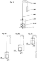
- Fig. 5 gives an overview of the main dimensions of a lift system.
- the car 2 with the empty mass MK is connected to a suspension element 4 which has the mass MT to the counterweight 3.
- the counterweight 3 has the mass MC.
- the drive 5, which drives the car 2 and the counterweight 3 via the suspension element 4, has a mass equivalent MA which corresponds to the rotational mass of the drive components 5.
- the car 2 is loaded with a maximum allowable delivery load 10 which corresponds to the mass MF.
- the cabin 2 is provided with a braking device 11.
- the Fig. 6a to 6c give a representation of possible measurement points for the commissioning of the braking device 11 and the elevator system 1.
- the cabin is unloaded, that is, the current mass MF is zero.
- the Fig. 6a to 6c are related to Fig. 5 consider.
- the measuring point is shown in the lowest stop HB.
- the mass fraction MT of the suspension element 4 is substantially on the side of the car 2.
- the measurement FB corresponds to the preponderance of counterweight 2 to empty cabin 2 and suspension means 4th
- Fig. 6b a measuring point is shown in the middle stop HM.
- Cabin 2 and counterweight 3 are at the same height and the mass fraction MT of the suspension element 4 is divided substantially evenly on the side of the car 2 and the counterweight 3.
- the measurement FB corresponds to the sole preponderance of counterweight 2 to empty cabin 2.
- Fig. 6c the measuring point is shown in the uppermost stop HT.
- the mass fraction MT of the suspension element 4 is substantially on the side of the counterweight 3.
- the measurement FB corresponds to the preponderance of counterweight 2 and support means 4 to the empty cabin 2.
- the measuring point according to Fig. 6b Of course, it can also be calculated as the mean value between the measured value Fig. 6a and 6c determine.
- the elevator expert can arbitrarily change the set shapes and arrangements.
- the illustrated arrangement of a drive in the shaft head can be replaced by a drive on the car or on the counterweight or the braking device can be arranged at the upper end of the cabin or below and above the cabin or laterally of the cabin.
Claims (18)
- Procédé pour contrôler un dispositif de freinage d'ascenseur, le dispositif de freinage d'ascenseur (11) freine et arrête une cabine d'ascenseur (2), et le dispositif de freinage d'ascenseur (11) se compose d'au moins deux unités de freinage (12) qui sont accouplées en cas de besoin à des glissières de frein (6), l'unité de freinage (12) pressant à cet effet au moins une plaque de frein (14) contre la glissière de frein (6) et produisant une force de freinage (FB), et un coefficient de friction effectif (µe) de l'unité de freinage (12) produit lors de la pression de la plaque de frein (14) contre la glissière de frein (6) étant déterminé, caractérisé en ce que le coefficient de friction effectif (µe) de l'unité de frein (12) est déterminé à l'aide d'un dispositif de mesure de force de freinage (20) destiné à mesurer une force de freinage (FB) et à l'aide d'un dispositif de mesure de force normale (21) destiné à mesurer une force d'approche de frein active (FNw).
- Procédé selon la revendication 1, caractérisé en ce que pour déterminer le coefficient de friction effectif (µe) de l'unité de freinage (12), ladite unité de freinage (12) est accouplée à la glissière de frein (6) et est approchée avec une faible force d'approche de frein active (FNw), et la cabine d'ascenseur (2) est déplacée à une vitesse faible, le déplacement étant poursuivi ou répété jusqu'à ce qu'un coefficient de friction effectif globalement constant de l'unité de frein (µe=FB/FNw) apparaisse.
- Procédé selon la revendication 2, caractérisé en ce que la détermination du coefficient de friction effectif (µe) de l'unité de frein (12) est réalisée sur la cabine d'ascenseur (2) non chargée.
- Procédé selon l'une des revendications 1 à 3, caractérisé en ce qu'à l'aide du coefficient de friction effectif (µe) et d'une force d'approche de frein maximale (FNm) déterminée à l'aide du dispositif de mesure de force normale, un facteur de sécurité de frein (SB) suffisant est mis en évidence.
- Procédé pour la mise en service d'une installation d'ascenseur (1) avec une cabine d'ascenseur (2) pour le transport d'une charge (10) et avec un contrepoids (3) qui est relié à l'aide de moyens porteurs (4) à la cabine d'ascenseur (2), et un entraînement (5) pour entraîner la cabine (2), le contrepoids (3) et les moyens porteurs (4), le contrepoids (3) et la cabine (2) se déplaçant en sens inverse dans une gaine verticale (7), et avec un dispositif de freinage d'ascenseur (11) installé sur la cabine d'ascenseur (2), caractérisé en ce qu'un contrôle du dispositif de freinage d'ascenseur (11) est réalisé à l'aide du procédé selon l'une des revendications 1 à 4.
- Procédé selon la revendication 5, caractérisé en ce qu'une masse restante (MV) de l'installation d'ascenseur à freiner dans le "pire des cas" par le dispositif de freinage d'ascenseur (11) est calculée (MV=MK+MF) à l'aide d'un poids autorisé (MF) de la charge à transporter (10) et d'un poids (MK) de la cabine d'ascenseur (2) vide, ou à l'aide du poids autorisé (MF) de la charge à transporter (10), d'une part de masse active de l'entraînement (MA) et de la mesure d'une accélération d'ascenseur (ak), des définitions de masse sur l'installation d'ascenseur ainsi qu'un déséquilibre réel (MB) de l'installation d'ascenseur ou un poids réel (MT) des moyens porteurs (4) étant réalisés à l'aide du dispositif de mesure de force de freinage.
- Procédé selon la revendication 5, caractérisé en ce qu'une force d'approche de frein maximale nécessaire (FNe) est définie en prenant en compte la masse totale (MV) à freiner dans le "pire des cas", le coefficient de friction effectif de l'unité de freinage (µe), le nombre d'unités de freinage (N) utilisées, un ralentissement minimal nécessaire (AKE) et un facteur de correction (KB1), le facteur de correction (KB) prenant en compte des valeurs d'expérience caractéristiques telles que la vitesse de freinage, l'encrassement ou une surcharge à prévoir : FNe=KB1*MV*(ak+g)/(N*/µe).
- Procédé selon la revendication 7, caractérisé en ce que l'unité de freinage (12) est approchée avec une force maximale, et à l'aide du dispositif de mesure de force normale (21) la force d'approche de frein maximale pouvant ainsi être atteinte (FNm) est mesurée, et cette force d'approche de frein maximale (FNm) est comparée à la force d'approche de frein maximale nécessaire (FNe), et la mise en évidence d'une fonction de freinage suffisante est jugée satisfaite si la force d'approche de frein maximale (FNm) est supérieure suivant le facteur de sécurité (SB) à la force d'approche de frein nécessaire (FNe).
- Procédé selon la revendication 8, caractérisé en ce que l'unité de freinage (12) est approchée avec une force maximale, et à l'aide du dispositif de mesure de force normale la force d'approche de freinage maximale pouvant ainsi être atteinte (FNm) est mesurée, et en prenant en compte le coefficient de friction effectif de l'unité de freinage (µe), le nombre d'unités de freinage (N) utilisées et un facteur de correction (KB2) - le facteur de correction (KB2) prenant en compte des valeurs d'expérience caractéristiques telles que la vitesse de freinage ou l'encrassement - une force de freinage maximale possible (FBm=KB2*FNm*N*µe) est définie.
- Procédé selon la revendication 9, caractérisé en ce qu'une force de freinage maximale nécessaire (FBe) est définie en prenant en compte le poids (MV) à freiner "dans le pire des cas", un ralentissement minimal nécessaire (ake) et un facteur de correction (KB2'), le facteur de correction (KB2') prenant en compte des valeurs d'expérience caractéristiques telles qu'une surcharge à prévoir (FBe=KB2'*MV*(ake+g)), et la force de freinage maximale possible (FNm) est comparée à la force de freinage maximale nécessaire (FBe), et la mise en évidence d'une fonction de freinage suffisante est jugée satisfaite si la force de freinage maximale possible (FBm) est supérieure suivant le facteur de sécurité (SB) à la force de freinage maximale nécessaire (FBe).
- Procédé selon l'une des revendications 5 à 10, caractérisé en ce que la fonction de freinage est vérifiée grâce au fait que la cabine vide (2) est accélérée de manière contrôlée ou non contrôlée, de préférence dans le sens montant, jusqu'à ce qu'un système de surveillance de vitesse active le dispositif de freinage (11) et que le dispositif de freinage (11) freine jusqu'à l'arrêt et maintienne à l'arrêt la cabine (2) à l'aide de la ou des unités de freinage (12) associées, étant précisé que pendant l'opération de freinage, les forces d'approche de de frein (FN) et les forces de freinage (FB) sont mesurées et qu'un coefficient de friction actuel (µb) de l'unité de freinage déterminé à partir de ces mesures est comparé au coefficient de friction effectif de l'unité de freinage (µe) déterminé précédemment, et la mise en service du dispositif de freinage (11) est jugée satisfaite si le coefficient de friction actuel (µb) déterminé coïncide globalement avec le coefficient de friction effectif (µe), au mieux en prenant en compte le facteur de correction (KB1, KB2).
- Procédé selon l'une des revendications 5 à 11, caractérisé en ce qu'un équilibrage correct d'un système d'ascenseur (1) est réalisé ou vérifié à l'aide du dispositif de mesure de force de freinage (20).
- Procédé selon la revendication 12, caractérisé en ce qu'un équilibrage du système d'ascenseur (1) est réalisé en entrant un facteur d'équilibrage demandé, un facteur d'équilibrage réel est déterminé à un arrêt supérieur (HT) et à un arrêt inférieur (HB) en mesurant la somme des forces de freinage du nombre (N) d'unités de freinage (12) dans les deux positions alors que la cabine d'ascenseur vide (2) est à l'arrêt, et une valeur moyenne de ces deux mesures est mise en relation avec la charge utile autorisée (MF) de la cabine d'ascenseur, et un poids supplémentaire nécessaire est déterminé sous la forme d'une différence du facteur d'équilibrage (Bg) demandé moins le facteur d'équilibrage réel (Bw) et la multiplication avec la charge utile autorisée (MF), et un contrepoids est lesté avec un poids supplémentaire ou déchargé en conséquence en cas de résultat négatif.
- Procédé selon l'une des revendications 5 à 13, caractérisé en ce que le nombre d'unités de freinage (12) utilisées est de deux ou d'un multiple de deux.
- Procédé selon l'une des revendications 5 à 14, caractérisé en ce que dans le cadre de la mise en service, des grandeurs caractéristiques de l'unité de freinage (12) sont détectées, leur concordance avec des valeurs prédéfinies est vérifiée et est mise en mémoire en vue du contrôle d'une fonction en fonctionnement normal, un contrôle d'état permanent (17) comparant à chaque utilisation du dispositif de freinage (11) en fonctionnement normal les valeurs caractéristiques, les comparant avec les valeurs de mise en service, et en cas d'écarts inattendus, un recalibrage, un message de service ou un message d'incident étant généré.
- Procédé selon la revendication 15, caractérisé en ce qu'on utilise comme grandeur caractéristique le coefficient de friction effectif (µe) déterminé, et/ou on utilise comme grandeur caractéristique une courbe caractéristique de force normale déterminée qui est stockée sous la forme d'une fonction d'un dispositif de mesure d'approche.
- Procédé selon la revendication 5, caractérisé en ce qu'une fonction correcte du dispositif de mesure de force de freinage (20) est surveillée à l'aide de la comparaison d'une force de freinage (FB) mesurée, avec une force d'entraînement (FA) nécessaire pour déplacer la cabine d'ascenseur (2), étant précisé qu'à cet effet une force de freinage statique (FBst) est mesurée avec la cabine d'ascenseur (2) à l'arrêt, et qu'une force de freinage dynamique (FBdyn) est mesurée à une vitesse de déplacement constante et en présence d'une force d'approche de frein active (FBw) plus faible, et que la différence entre ces deux mesures (FBdyn-Fbstat) est comparée à la force d'entraînement (FA) nécessaire, par exemple un couple de moteur.
- Dispositif pour exécuter une mise en service selon l'une des revendications 5 à 17, caractérisé en ce que le dispositif (9) est apte à être raccordé au dispositif de freinage (11), et commande le déroulement de la mise en service.
Priority Applications (3)
| Application Number | Priority Date | Filing Date | Title |
|---|---|---|---|
| EP07109524.4A EP1870369B1 (fr) | 2006-06-19 | 2007-06-04 | Procédé destiné à la vérification d'un dispositif de frein de levage, un procédé destiné à la mise en service d'une installation de levage et un dispositif destiné à l'exécution d'une mise en service |
| PL07109524T PL1870369T3 (pl) | 2006-06-19 | 2007-06-04 | Sposób sprawdzania urządzenia hamującego dźwigu, sposób uruchamiania instalacji dźwigowej i urządzenie do przeprowadzania uruchomienia |
| EP10183872.0A EP2316776B1 (fr) | 2006-06-19 | 2007-06-04 | Procédé pour la mise en service d'un système d'ascenseur |
Applications Claiming Priority (2)
| Application Number | Priority Date | Filing Date | Title |
|---|---|---|---|
| EP06115686 | 2006-06-19 | ||
| EP07109524.4A EP1870369B1 (fr) | 2006-06-19 | 2007-06-04 | Procédé destiné à la vérification d'un dispositif de frein de levage, un procédé destiné à la mise en service d'une installation de levage et un dispositif destiné à l'exécution d'une mise en service |
Related Child Applications (2)
| Application Number | Title | Priority Date | Filing Date |
|---|---|---|---|
| EP10183872.0A Division EP2316776B1 (fr) | 2006-06-19 | 2007-06-04 | Procédé pour la mise en service d'un système d'ascenseur |
| EP10183872.0A Division-Into EP2316776B1 (fr) | 2006-06-19 | 2007-06-04 | Procédé pour la mise en service d'un système d'ascenseur |
Publications (2)
| Publication Number | Publication Date |
|---|---|
| EP1870369A1 EP1870369A1 (fr) | 2007-12-26 |
| EP1870369B1 true EP1870369B1 (fr) | 2018-01-10 |
Family
ID=38719714
Family Applications (2)
| Application Number | Title | Priority Date | Filing Date |
|---|---|---|---|
| EP10183872.0A Active EP2316776B1 (fr) | 2006-06-19 | 2007-06-04 | Procédé pour la mise en service d'un système d'ascenseur |
| EP07109524.4A Active EP1870369B1 (fr) | 2006-06-19 | 2007-06-04 | Procédé destiné à la vérification d'un dispositif de frein de levage, un procédé destiné à la mise en service d'une installation de levage et un dispositif destiné à l'exécution d'une mise en service |
Family Applications Before (1)
| Application Number | Title | Priority Date | Filing Date |
|---|---|---|---|
| EP10183872.0A Active EP2316776B1 (fr) | 2006-06-19 | 2007-06-04 | Procédé pour la mise en service d'un système d'ascenseur |
Country Status (2)
| Country | Link |
|---|---|
| EP (2) | EP2316776B1 (fr) |
| PL (1) | PL1870369T3 (fr) |
Families Citing this family (8)
| Publication number | Priority date | Publication date | Assignee | Title |
|---|---|---|---|---|
| US8210319B2 (en) * | 2007-08-31 | 2012-07-03 | John W. Boyd | Hydraulic elevating platform assembly |
| DE102009053131B3 (de) * | 2009-11-05 | 2011-05-19 | Db Services West Gmbh | Verfahren und Vorrichtung zum Überprüfen des Bremssystems einer Aufzugsanlage |
| DE202011051664U1 (de) | 2011-10-18 | 2012-01-13 | Slc Sautter Lift Components Gmbh & Co. Kg | Bremseinrichtung für einen Aufzug |
| CN103226351B (zh) * | 2013-03-18 | 2015-08-19 | 康力电梯股份有限公司 | 一种扶梯附加制动器测试系统 |
| DE102014206461A1 (de) | 2014-04-03 | 2015-10-08 | Thyssen Krupp Elevator Ag | Aufzug mit einer Bremsvorrichtung |
| DE102014213404A1 (de) * | 2014-07-10 | 2016-01-14 | Thyssenkrupp Ag | Aufzugsanlage mit Bremseinrichtung am Fahrkorb und Verfahren zum Betrieb der Selbigen |
| AU2016363505B2 (en) | 2015-12-02 | 2019-07-18 | Inventio Ag | Method for driving a brake device of a lift system |
| CN113247731B (zh) * | 2021-06-30 | 2023-04-07 | 洛阳智超机电科技有限公司 | 一种多绳提升机系统负荷检测及安全制动控制方法 |
Family Cites Families (5)
| Publication number | Priority date | Publication date | Assignee | Title |
|---|---|---|---|---|
| ES2121175T3 (es) * | 1993-08-24 | 1998-11-16 | Garaventa Holding Ag | Dispositivo de bloqueo y de enganche para el carro guiado sobre carriles de un ascensor oblicuo o vertical. |
| JP2001192184A (ja) * | 2000-01-11 | 2001-07-17 | Toshiba Corp | エレベータ非常止め装置 |
| DE10306375B3 (de) * | 2003-02-15 | 2004-10-14 | Henning Gmbh | Verfahren zur Überprüfung von Fangvorrichtungen |
| AU2003300127A1 (en) * | 2003-12-31 | 2005-08-03 | Otis Elevator Company | Elevator safety device |
| MY192706A (en) * | 2004-12-17 | 2022-09-02 | Inventio Ag | Lift installation with a braking device, and method for braking and holding a lift installation |
-
2007
- 2007-06-04 EP EP10183872.0A patent/EP2316776B1/fr active Active
- 2007-06-04 EP EP07109524.4A patent/EP1870369B1/fr active Active
- 2007-06-04 PL PL07109524T patent/PL1870369T3/pl unknown
Non-Patent Citations (1)
| Title |
|---|
| None * |
Also Published As
| Publication number | Publication date |
|---|---|
| EP1870369A1 (fr) | 2007-12-26 |
| EP2316776B1 (fr) | 2019-10-09 |
| EP2316776A1 (fr) | 2011-05-04 |
| PL1870369T3 (pl) | 2018-06-29 |
Similar Documents
| Publication | Publication Date | Title |
|---|---|---|
| EP1870369B1 (fr) | Procédé destiné à la vérification d'un dispositif de frein de levage, un procédé destiné à la mise en service d'une installation de levage et un dispositif destiné à l'exécution d'une mise en service | |
| EP0391174B2 (fr) | Dispositif et méthode pour détecter des paramètres physiques d'un élévateur | |
| EP1067084B1 (fr) | Dispositif et méthode pour éviter les glissements et les oscillations verticales sur des appareils de prise de charge pour des installations de transport vertical | |
| EP1671912B1 (fr) | Système d'ascenseur avec unité de freinage et méthode pour mantenir l'ascenseur en position arrêtée | |
| EP1401757B2 (fr) | Procede pour empecher une vitesse inacceptablement elevee du moyen de suspension de charge d'un ascenseur | |
| DE102014101381B4 (de) | Messsystem und Messverfahren zur Prüfung der Fangvorrichtung eines Aufzugs | |
| EP0755894B1 (fr) | Procédé et dispositif pour mesurer la charge dans une cabine d'ascenseur | |
| EP2170753A1 (fr) | Installation d'ascenseur comprenant une cabine d'ascenseur, un dispositif de freinage pour immobiliser une cabine d'ascenseur dans un mode de fonctionnement special et procede pour immobiliser une cabine d'ascenseur dans un mode de fonctionnement special | |
| DE112015006721T5 (de) | Aufzugsvorrichtung | |
| DE4217587C2 (de) | Anlagen-Diagnoseverfahren | |
| DE102006042909B4 (de) | Dynamische Bestimmung der Treibfähigkeit bei Treibscheiben-getriebenen Aufzugsanlagen | |
| EP0563836B1 (fr) | Méthode pour mesurer la capacité d'entraînement d'une installation de transport | |
| DE112014007092T5 (de) | Aufzugsteuervorrichtung | |
| DE112016002403T5 (de) | Fahrstuhlvorrichtung, Steuerungsverfahren dafür, sowie Zustandsbestimmungseinrichtung für Fahrstuhl am entfernten Ort | |
| DE10144913B4 (de) | Aufzugbremslast-Wägesystem | |
| EP1561718A2 (fr) | Méthode pour surveiller l'effet freinant sur un système d'ascenseur | |
| DE112014005549T5 (de) | Aufzugsanlage und Verfahren zu ihrer Steuerung | |
| DE4311011C2 (de) | Verfahren und Vorrichtung zur Prüfung eines Aufzugs mit Treibscheibenantrieb | |
| EP0643290A1 (fr) | Dispositif pour tester, surveiller et régler des freins mécaniques | |
| EP3774630A1 (fr) | Procédé et dispositif servant à surveiller des propriétés d'un ensemble de moyens de support dans un système d'ascenseur | |
| DE202014010222U1 (de) | Vorrichtung zur Erfassung wenigstens eines Bewegungsparameters einer triebwerksraumlosen Treibscheibenaufzugsanlage | |
| WO2016005429A1 (fr) | Installation d'ascenseur équipée d'un dispositif de freinage sur la cabine et procédé servant à faire fonctionner ladite installation d'ascenseur | |
| DE102017202589A1 (de) | Verfahren und Vorrichtung zur Ermittlung der Treibfähigkeit einer Förderanlage über eine Drehmomentmessung | |
| DE10343193B4 (de) | Steuerungs- und Regelungseinrichtung für einen Aufzug | |
| DE102007009602A1 (de) | Treibfähigkeitsmessung an Treibscheibenaufzugsanlagen |
Legal Events
| Date | Code | Title | Description |
|---|---|---|---|
| PUAI | Public reference made under article 153(3) epc to a published international application that has entered the european phase |
Free format text: ORIGINAL CODE: 0009012 |
|
| AK | Designated contracting states |
Kind code of ref document: A1 Designated state(s): AT BE BG CH CY CZ DE DK EE ES FI FR GB GR HU IE IS IT LI LT LU LV MC MT NL PL PT RO SE SI SK TR |
|
| AX | Request for extension of the european patent |
Extension state: AL BA HR MK YU |
|
| 17P | Request for examination filed |
Effective date: 20080529 |
|
| 17Q | First examination report despatched |
Effective date: 20080620 |
|
| AKX | Designation fees paid |
Designated state(s): AT BE BG CH CY CZ DE DK EE ES FI FR GB GR HU IE IS IT LI LT LU LV MC MT NL PL PT RO SE SI SK TR |
|
| REG | Reference to a national code |
Ref country code: HK Ref legal event code: DE Ref document number: 1116754 Country of ref document: HK |
|
| RIN1 | Information on inventor provided before grant (corrected) |
Inventor name: GRUNDMANN, STEFFEN Inventor name: GREMAUD, NICOLAS |
|
| GRAP | Despatch of communication of intention to grant a patent |
Free format text: ORIGINAL CODE: EPIDOSNIGR1 |
|
| INTG | Intention to grant announced |
Effective date: 20170816 |
|
| GRAS | Grant fee paid |
Free format text: ORIGINAL CODE: EPIDOSNIGR3 |
|
| GRAA | (expected) grant |
Free format text: ORIGINAL CODE: 0009210 |
|
| AK | Designated contracting states |
Kind code of ref document: B1 Designated state(s): AT BE BG CH CY CZ DE DK EE ES FI FR GB GR HU IE IS IT LI LT LU LV MC MT NL PL PT RO SE SI SK TR |
|
| REG | Reference to a national code |
Ref country code: GB Ref legal event code: FG4D Free format text: NOT ENGLISH |
|
| REG | Reference to a national code |
Ref country code: CH Ref legal event code: EP Ref country code: AT Ref legal event code: REF Ref document number: 962158 Country of ref document: AT Kind code of ref document: T Effective date: 20180115 |
|
| REG | Reference to a national code |
Ref country code: IE Ref legal event code: FG4D Free format text: LANGUAGE OF EP DOCUMENT: GERMAN |
|
| REG | Reference to a national code |
Ref country code: DE Ref legal event code: R096 Ref document number: 502007016015 Country of ref document: DE |
|
| REG | Reference to a national code |
Ref country code: ES Ref legal event code: FG2A Ref document number: 2659923 Country of ref document: ES Kind code of ref document: T3 Effective date: 20180320 |
|
| REG | Reference to a national code |
Ref country code: NL Ref legal event code: MP Effective date: 20180110 |
|
| REG | Reference to a national code |
Ref country code: FR Ref legal event code: PLFP Year of fee payment: 12 |
|
| PG25 | Lapsed in a contracting state [announced via postgrant information from national office to epo] |
Ref country code: NL Free format text: LAPSE BECAUSE OF FAILURE TO SUBMIT A TRANSLATION OF THE DESCRIPTION OR TO PAY THE FEE WITHIN THE PRESCRIBED TIME-LIMIT Effective date: 20180110 |
|
| PG25 | Lapsed in a contracting state [announced via postgrant information from national office to epo] |
Ref country code: CY Free format text: LAPSE BECAUSE OF FAILURE TO SUBMIT A TRANSLATION OF THE DESCRIPTION OR TO PAY THE FEE WITHIN THE PRESCRIBED TIME-LIMIT Effective date: 20180110 Ref country code: LT Free format text: LAPSE BECAUSE OF FAILURE TO SUBMIT A TRANSLATION OF THE DESCRIPTION OR TO PAY THE FEE WITHIN THE PRESCRIBED TIME-LIMIT Effective date: 20180110 Ref country code: FI Free format text: LAPSE BECAUSE OF FAILURE TO SUBMIT A TRANSLATION OF THE DESCRIPTION OR TO PAY THE FEE WITHIN THE PRESCRIBED TIME-LIMIT Effective date: 20180110 |
|
| PG25 | Lapsed in a contracting state [announced via postgrant information from national office to epo] |
Ref country code: BG Free format text: LAPSE BECAUSE OF FAILURE TO SUBMIT A TRANSLATION OF THE DESCRIPTION OR TO PAY THE FEE WITHIN THE PRESCRIBED TIME-LIMIT Effective date: 20180410 Ref country code: LV Free format text: LAPSE BECAUSE OF FAILURE TO SUBMIT A TRANSLATION OF THE DESCRIPTION OR TO PAY THE FEE WITHIN THE PRESCRIBED TIME-LIMIT Effective date: 20180110 Ref country code: SE Free format text: LAPSE BECAUSE OF FAILURE TO SUBMIT A TRANSLATION OF THE DESCRIPTION OR TO PAY THE FEE WITHIN THE PRESCRIBED TIME-LIMIT Effective date: 20180110 Ref country code: GR Free format text: LAPSE BECAUSE OF FAILURE TO SUBMIT A TRANSLATION OF THE DESCRIPTION OR TO PAY THE FEE WITHIN THE PRESCRIBED TIME-LIMIT Effective date: 20180411 Ref country code: IS Free format text: LAPSE BECAUSE OF FAILURE TO SUBMIT A TRANSLATION OF THE DESCRIPTION OR TO PAY THE FEE WITHIN THE PRESCRIBED TIME-LIMIT Effective date: 20180510 |
|
| PG25 | Lapsed in a contracting state [announced via postgrant information from national office to epo] |
Ref country code: MT Free format text: LAPSE BECAUSE OF FAILURE TO SUBMIT A TRANSLATION OF THE DESCRIPTION OR TO PAY THE FEE WITHIN THE PRESCRIBED TIME-LIMIT Effective date: 20180110 |
|
| REG | Reference to a national code |
Ref country code: DE Ref legal event code: R097 Ref document number: 502007016015 Country of ref document: DE |
|
| PG25 | Lapsed in a contracting state [announced via postgrant information from national office to epo] |
Ref country code: RO Free format text: LAPSE BECAUSE OF FAILURE TO SUBMIT A TRANSLATION OF THE DESCRIPTION OR TO PAY THE FEE WITHIN THE PRESCRIBED TIME-LIMIT Effective date: 20180110 Ref country code: EE Free format text: LAPSE BECAUSE OF FAILURE TO SUBMIT A TRANSLATION OF THE DESCRIPTION OR TO PAY THE FEE WITHIN THE PRESCRIBED TIME-LIMIT Effective date: 20180110 |
|
| PLBE | No opposition filed within time limit |
Free format text: ORIGINAL CODE: 0009261 |
|
| STAA | Information on the status of an ep patent application or granted ep patent |
Free format text: STATUS: NO OPPOSITION FILED WITHIN TIME LIMIT |
|
| PG25 | Lapsed in a contracting state [announced via postgrant information from national office to epo] |
Ref country code: DK Free format text: LAPSE BECAUSE OF FAILURE TO SUBMIT A TRANSLATION OF THE DESCRIPTION OR TO PAY THE FEE WITHIN THE PRESCRIBED TIME-LIMIT Effective date: 20180110 Ref country code: CZ Free format text: LAPSE BECAUSE OF FAILURE TO SUBMIT A TRANSLATION OF THE DESCRIPTION OR TO PAY THE FEE WITHIN THE PRESCRIBED TIME-LIMIT Effective date: 20180110 Ref country code: SK Free format text: LAPSE BECAUSE OF FAILURE TO SUBMIT A TRANSLATION OF THE DESCRIPTION OR TO PAY THE FEE WITHIN THE PRESCRIBED TIME-LIMIT Effective date: 20180110 |
|
| 26N | No opposition filed |
Effective date: 20181011 |
|
| PG25 | Lapsed in a contracting state [announced via postgrant information from national office to epo] |
Ref country code: SI Free format text: LAPSE BECAUSE OF FAILURE TO SUBMIT A TRANSLATION OF THE DESCRIPTION OR TO PAY THE FEE WITHIN THE PRESCRIBED TIME-LIMIT Effective date: 20180110 |
|
| REG | Reference to a national code |
Ref country code: BE Ref legal event code: MM Effective date: 20180630 |
|
| REG | Reference to a national code |
Ref country code: IE Ref legal event code: MM4A |
|
| PG25 | Lapsed in a contracting state [announced via postgrant information from national office to epo] |
Ref country code: LU Free format text: LAPSE BECAUSE OF NON-PAYMENT OF DUE FEES Effective date: 20180604 Ref country code: MC Free format text: LAPSE BECAUSE OF FAILURE TO SUBMIT A TRANSLATION OF THE DESCRIPTION OR TO PAY THE FEE WITHIN THE PRESCRIBED TIME-LIMIT Effective date: 20180110 |
|
| PG25 | Lapsed in a contracting state [announced via postgrant information from national office to epo] |
Ref country code: IE Free format text: LAPSE BECAUSE OF NON-PAYMENT OF DUE FEES Effective date: 20180604 |
|
| PG25 | Lapsed in a contracting state [announced via postgrant information from national office to epo] |
Ref country code: BE Free format text: LAPSE BECAUSE OF NON-PAYMENT OF DUE FEES Effective date: 20180630 |
|
| PG25 | Lapsed in a contracting state [announced via postgrant information from national office to epo] |
Ref country code: PT Free format text: LAPSE BECAUSE OF FAILURE TO SUBMIT A TRANSLATION OF THE DESCRIPTION OR TO PAY THE FEE WITHIN THE PRESCRIBED TIME-LIMIT Effective date: 20180110 Ref country code: HU Free format text: LAPSE BECAUSE OF FAILURE TO SUBMIT A TRANSLATION OF THE DESCRIPTION OR TO PAY THE FEE WITHIN THE PRESCRIBED TIME-LIMIT; INVALID AB INITIO Effective date: 20070604 |
|
| PGFP | Annual fee paid to national office [announced via postgrant information from national office to epo] |
Ref country code: IT Payment date: 20210622 Year of fee payment: 15 |
|
| PGFP | Annual fee paid to national office [announced via postgrant information from national office to epo] |
Ref country code: PL Payment date: 20210526 Year of fee payment: 15 Ref country code: AT Payment date: 20210618 Year of fee payment: 15 Ref country code: TR Payment date: 20210525 Year of fee payment: 15 |
|
| PGFP | Annual fee paid to national office [announced via postgrant information from national office to epo] |
Ref country code: ES Payment date: 20210713 Year of fee payment: 15 |
|
| REG | Reference to a national code |
Ref country code: AT Ref legal event code: MM01 Ref document number: 962158 Country of ref document: AT Kind code of ref document: T Effective date: 20220604 |
|
| PG25 | Lapsed in a contracting state [announced via postgrant information from national office to epo] |
Ref country code: AT Free format text: LAPSE BECAUSE OF NON-PAYMENT OF DUE FEES Effective date: 20220604 |
|
| REG | Reference to a national code |
Ref country code: ES Ref legal event code: FD2A Effective date: 20230726 |
|
| PG25 | Lapsed in a contracting state [announced via postgrant information from national office to epo] |
Ref country code: IT Free format text: LAPSE BECAUSE OF NON-PAYMENT OF DUE FEES Effective date: 20220604 |
|
| PGFP | Annual fee paid to national office [announced via postgrant information from national office to epo] |
Ref country code: FR Payment date: 20230622 Year of fee payment: 17 Ref country code: DE Payment date: 20230627 Year of fee payment: 17 |
|
| REG | Reference to a national code |
Ref country code: DE Ref legal event code: R084 Ref document number: 502007016015 Country of ref document: DE |
|
| PG25 | Lapsed in a contracting state [announced via postgrant information from national office to epo] |
Ref country code: PL Free format text: LAPSE BECAUSE OF NON-PAYMENT OF DUE FEES Effective date: 20220604 |
|
| PG25 | Lapsed in a contracting state [announced via postgrant information from national office to epo] |
Ref country code: ES Free format text: LAPSE BECAUSE OF NON-PAYMENT OF DUE FEES Effective date: 20220605 |
|
| PGFP | Annual fee paid to national office [announced via postgrant information from national office to epo] |
Ref country code: GB Payment date: 20230620 Year of fee payment: 17 Ref country code: CH Payment date: 20230702 Year of fee payment: 17 |