EP1867958A2 - Positionssensor - Google Patents
Positionssensor Download PDFInfo
- Publication number
- EP1867958A2 EP1867958A2 EP07107375A EP07107375A EP1867958A2 EP 1867958 A2 EP1867958 A2 EP 1867958A2 EP 07107375 A EP07107375 A EP 07107375A EP 07107375 A EP07107375 A EP 07107375A EP 1867958 A2 EP1867958 A2 EP 1867958A2
- Authority
- EP
- European Patent Office
- Prior art keywords
- guide
- optical
- light
- hinge
- optical wave
- Prior art date
- Legal status (The legal status is an assumption and is not a legal conclusion. Google has not performed a legal analysis and makes no representation as to the accuracy of the status listed.)
- Withdrawn
Links
Images




Classifications
-
- H—ELECTRICITY
- H04—ELECTRIC COMMUNICATION TECHNIQUE
- H04B—TRANSMISSION
- H04B1/00—Details of transmission systems, not covered by a single one of groups H04B3/00 - H04B13/00; Details of transmission systems not characterised by the medium used for transmission
- H04B1/38—Transceivers, i.e. devices in which transmitter and receiver form a structural unit and in which at least one part is used for functions of transmitting and receiving
- H04B1/40—Circuits
-
- H—ELECTRICITY
- H04—ELECTRIC COMMUNICATION TECHNIQUE
- H04M—TELEPHONIC COMMUNICATION
- H04M1/00—Substation equipment, e.g. for use by subscribers
- H04M1/02—Constructional features of telephone sets
- H04M1/0202—Portable telephone sets, e.g. cordless phones, mobile phones or bar type handsets
- H04M1/0206—Portable telephones comprising a plurality of mechanically joined movable body parts, e.g. hinged housings
- H04M1/0241—Portable telephones comprising a plurality of mechanically joined movable body parts, e.g. hinged housings using relative motion of the body parts to change the operational status of the telephone set, e.g. switching on/off, answering incoming call
- H04M1/0243—Portable telephones comprising a plurality of mechanically joined movable body parts, e.g. hinged housings using relative motion of the body parts to change the operational status of the telephone set, e.g. switching on/off, answering incoming call using the relative angle between housings
-
- G—PHYSICS
- G01—MEASURING; TESTING
- G01D—MEASURING NOT SPECIALLY ADAPTED FOR A SPECIFIC VARIABLE; ARRANGEMENTS FOR MEASURING TWO OR MORE VARIABLES NOT COVERED IN A SINGLE OTHER SUBCLASS; TARIFF METERING APPARATUS; MEASURING OR TESTING NOT OTHERWISE PROVIDED FOR
- G01D5/00—Mechanical means for transferring the output of a sensing member; Means for converting the output of a sensing member to another variable where the form or nature of the sensing member does not constrain the means for converting; Transducers not specially adapted for a specific variable
- G01D5/26—Mechanical means for transferring the output of a sensing member; Means for converting the output of a sensing member to another variable where the form or nature of the sensing member does not constrain the means for converting; Transducers not specially adapted for a specific variable characterised by optical transfer means, i.e. using infrared, visible, or ultraviolet light
- G01D5/32—Mechanical means for transferring the output of a sensing member; Means for converting the output of a sensing member to another variable where the form or nature of the sensing member does not constrain the means for converting; Transducers not specially adapted for a specific variable characterised by optical transfer means, i.e. using infrared, visible, or ultraviolet light with attenuation or whole or partial obturation of beams of light
- G01D5/34—Mechanical means for transferring the output of a sensing member; Means for converting the output of a sensing member to another variable where the form or nature of the sensing member does not constrain the means for converting; Transducers not specially adapted for a specific variable characterised by optical transfer means, i.e. using infrared, visible, or ultraviolet light with attenuation or whole or partial obturation of beams of light the beams of light being detected by photocells
- G01D5/353—Mechanical means for transferring the output of a sensing member; Means for converting the output of a sensing member to another variable where the form or nature of the sensing member does not constrain the means for converting; Transducers not specially adapted for a specific variable characterised by optical transfer means, i.e. using infrared, visible, or ultraviolet light with attenuation or whole or partial obturation of beams of light the beams of light being detected by photocells influencing the transmission properties of an optical fibre
- G01D5/35338—Mechanical means for transferring the output of a sensing member; Means for converting the output of a sensing member to another variable where the form or nature of the sensing member does not constrain the means for converting; Transducers not specially adapted for a specific variable characterised by optical transfer means, i.e. using infrared, visible, or ultraviolet light with attenuation or whole or partial obturation of beams of light the beams of light being detected by photocells influencing the transmission properties of an optical fibre using other arrangements than interferometer arrangements
- G01D5/35341—Sensor working in transmission
- G01D5/35345—Sensor working in transmission using Amplitude variations to detect the measured quantity
-
- G—PHYSICS
- G02—OPTICS
- G02B—OPTICAL ELEMENTS, SYSTEMS OR APPARATUS
- G02B6/00—Light guides; Structural details of arrangements comprising light guides and other optical elements, e.g. couplings
- G02B6/44—Mechanical structures for providing tensile strength and external protection for fibres, e.g. optical transmission cables
-
- G—PHYSICS
- G06—COMPUTING OR CALCULATING; COUNTING
- G06F—ELECTRIC DIGITAL DATA PROCESSING
- G06F1/00—Details not covered by groups G06F3/00 - G06F13/00 and G06F21/00
- G06F1/16—Constructional details or arrangements
- G06F1/1613—Constructional details or arrangements for portable computers
- G06F1/1615—Constructional details or arrangements for portable computers with several enclosures having relative motions, each enclosure supporting at least one I/O or computing function
- G06F1/1616—Constructional details or arrangements for portable computers with several enclosures having relative motions, each enclosure supporting at least one I/O or computing function with folding flat displays, e.g. laptop computers or notebooks having a clamshell configuration, with body parts pivoting to an open position around an axis parallel to the plane they define in closed position
-
- G—PHYSICS
- G06—COMPUTING OR CALCULATING; COUNTING
- G06F—ELECTRIC DIGITAL DATA PROCESSING
- G06F1/00—Details not covered by groups G06F3/00 - G06F13/00 and G06F21/00
- G06F1/16—Constructional details or arrangements
- G06F1/1613—Constructional details or arrangements for portable computers
- G06F1/1633—Constructional details or arrangements of portable computers not specific to the type of enclosures covered by groups G06F1/1615 - G06F1/1626
- G06F1/1675—Miscellaneous details related to the relative movement between the different enclosures or enclosure parts
- G06F1/1677—Miscellaneous details related to the relative movement between the different enclosures or enclosure parts for detecting open or closed state or particular intermediate positions assumed by movable parts of the enclosure, e.g. detection of display lid position with respect to main body in a laptop, detection of opening of the cover of battery compartment
-
- G—PHYSICS
- G06—COMPUTING OR CALCULATING; COUNTING
- G06F—ELECTRIC DIGITAL DATA PROCESSING
- G06F1/00—Details not covered by groups G06F3/00 - G06F13/00 and G06F21/00
- G06F1/16—Constructional details or arrangements
- G06F1/1613—Constructional details or arrangements for portable computers
- G06F1/1633—Constructional details or arrangements of portable computers not specific to the type of enclosures covered by groups G06F1/1615 - G06F1/1626
- G06F1/1675—Miscellaneous details related to the relative movement between the different enclosures or enclosure parts
- G06F1/1681—Details related solely to hinges
Definitions
- the present invention relates to an optical position sensor, particularly, but not exclusively, to a fibre optic position sensor for sensing the position of a hinged lid of a portable electronic device such as a mobile telephone or a lap-top computer.
- a portable electronic device such as a lap-top computer or a mobile telephone to comprise a base, which includes the device's keypad, and a lid, which includes the device's screen or user display.
- the base and the lid are connected together by a hinge section such that the user display can be hinged to lie flat against the keypad when the device is not in use.
- the hinge By detecting when the hinge is closed, the device is able to detect when it may safely switch to a power- saving mode. This function allows the device to conserve battery power when the device is not in use.
- a mechanical sensor such as a boss-type media detection switch or a rotary-type position detection switch.
- a mechanical sensor often imposes design constraints on the electronic device and may also require that bosses be fitted to the device's exterior.
- a mechanical sensor often also requires extra space on the motherboard of the device for the inclusion of a detector switch.
- the position of the hinge may be detected using a solid-state relay.
- a solid-state relay For example, it is known to magnetically detect the position of a lid with a system employing a Hall Integrated Circuit.
- this type of detector requires both space on the motherboard of the device and a level of standby power.
- magnetic switches of this type are liable to interfere with other types of sensor which may be integrated into the device, such as those employed by global positioning systems.
- a hinge-position detection apparatus comprising a first member and a second member rotationally connected to one another so as to provide a hinge, a first optical fibre, a light emitter to transmit light through the optical fibre and a light detector to detect a power level of light emitted from the optical fibre, wherein the optical fibre is physically distorted by actuation of the hinge and the detected power level is used to determine the position of the hinge.
- a physical distortion in the optical fibre may cause light to escape from the optical fibre and affect the optical power level detected by the light detector.
- the optical fibre may be connected between the first member and the second member so as to traverse the hinge.
- the determined position of the hinge may be used to control the operation of an electronic device.
- the apparatus may be configured to switch one or more components of an electronic device to a power saving mode.
- the hinge may be determined to be in a closed position if the detected optical power level reaches a predetermined threshold level.
- the light emitter may be included in the first member, the light detector may be included in the second member and the optical fibre may be coupled between the light emitter and the light detector.
- the light detector may be positioned to directly detect the emission of light from the optical fibre, the emission of light being caused by a physical distortion in the fibre.
- the apparatus may include a further optical fibre operable to direct the emission of light from the optical fibre to the detector.
- the light emitter may comprise an LED or a laser
- the light detector may comprise a photo-sensitive device, such as a photo-diode, photo-transistor or photo-resistor.
- a hinge position detection apparatus is part of a mobile telephone handset 11.
- the mobile telephone handset 11 comprises a first member in the form of a base 12 and a second member in the form of a lid 13.
- the base 12 and lid 13 are connected together by a hinge joint 14, allowing the handset 11 to be movable between a closed position and an open position.
- the telephone handset 11 is configured to operate in a cellular radio network, such as a GSM network, although it could be configured for use with other networks such as a 3G network or I-mode.
- a cellular radio network such as a GSM network
- GSM Global System for Mobile communications
- I-mode I-mode
- the telephone handset 11 is provided with a user display 15, for example in the form of a liquid crystal display (LCD) panel.
- the handset 11 is additionally provided with a loudspeaker 16, which is located in the lid 13 and is on the same surface as the user display 15.
- the base 12 of the handset 11 houses the remainder of the telephone's principal components, including a keypad 17.
- the keypad 17 is located on the surface of the base 12 such that, when the hinge joint 14 is in the closed position, the keypad 17 directly faces the user display 15. Thus, the user display 15 and keypad 17 are not visible to the user when the hinge 14 is closed.
- An antenna 18 is located inside the base 12 such that it does not form part of the handset's exterior.
- the handset 11 comprises a microphone 21, a SIM card 22, a SIM card reader 23, amplifiers 24 and 25, an rf subsystem 26, a codec 27, a micro-controller 28 and a memory 29.
- the rf subsystem 26 contains the circuits of the telephone's transmitter and receiver.
- the rf subsystem 26 is coupled to the antenna 18 for the reception and transmission of radio signals in a cellular mobile network.
- the antenna 18 is connected through the rf subsystem 26 to the codec 27, which is configured to process signals under the control of the micro-controller 28.
- the micro-controller 28 operates according to a program stored in the memory 29 and controls the operation of the handset 11. It is coupled to the rf subsystem 26 for supplying tuning instructions to a frequency synthesizer.
- the user display 15 is connected to the micro-controller 28 for receiving control data and the keypad 17 is connected to the micro-controller 28 for supplying user input data.
- the memory 29 is shown separately from the micro-controller 28. However, the memory 29 and the controller 28 may also be included together in an integrated unit.
- the amplifier 24 amplifies demodulated audio from the codec 27 and applies it to the loudspeaker 16. Acoustic signals, detected by the microphone 21, are preamplified by the amplifier 25 and sent to the codec 27 for coding.
- GSM SIM card which contains the usual GSM international mobile subscriber identity (IMSI) and an encryption key K i that is used for encoding the radio transmission in a manner that is well known.
- IMSI GSM international mobile subscriber identity
- K i an encryption key that is used for encoding the radio transmission in a manner that is well known.
- the SIM card is removably received in the SIM card reader 23.
- the handset 11 further comprises an optical wave-guide, for example an optical fibre 31, which is connected between the base 12 and the lid 13 via the hinge joint 14.
- the optical fibre 31 is connected so as to provide a transmission medium for optical communication between electronic circuits located in the base 12 and the lid 13.
- the base 12 of the handset 11 further includes a light emitter, for example a laser 41, which is adapted to emit red laser light in the wavelength range 630-670 nanometres.
- a light emitter for example a laser 41, which is adapted to emit red laser light in the wavelength range 630-670 nanometres.
- the laser 41 is coupled to the base-end of the optical fibre 31 and, as such, light emitted from the laser 41 enters the optical fibre 31 and is transmitted to the lid 13.
- the term "light” is used herein to mean electromagnetic radiation in the visible, infra-red and ultraviolet spectrum.
- the optical fibre 31 comprises a central core 31a surrounded by a cladding layer 31b.
- the refractive index of the core 31a is of a different refractive index to that of the cladding 31b, meaning that light is confined to the core 31a by total internal reflection and is guided along the optical fibre 31.
- the optical fibre 31 may be either a graded optical fibre or a step-index optical fibre.
- the light transmitted through the optical fibre 31 may carry, for example, signals for controlling the operation of the user display 15 or loudspeaker 16.
- light transmitted through the optical fibre 31 may comprise control data for illumination at the lid side of the handset 11.
- the laser 41 could be replaced by a lightemitted diode (LED).
- the lid 13 of the handset 11 includes a light detector, for example a photo-diode 42, which is coupled to the lid-end of the optical fibre 31.
- the photo-diode 42 is adapted to detect light transmitted through the fibre 31 from the laser 41 and is coupled to electronic circuits located in the lid 13 of the handset 11.
- the handset may comprise another type of photo-sensitive device such as a photo-transistor or photo-resistor.
- the optical fibre 31 is fabricated from suitable plastics and is flexible in such a way that it is able to bend with the hinge joint 14 of the telephone handset 11.
- the use of plastics allows the optical fibre 31 to be adapted such that it may be bent to a very small radius. This is convenient as the optical fibre 31 should be able to comfortably bend to a radius enabling it to traverse the hinge joint 14 when the handset 11 in the closed position.
- the use of plastics also provides advantages in terms of transmission speed and is inexpensive in comparison to alternative materials. However, it will be appreciated that materials other than plastics can be used.
- the optical fibre 31 is bent to the a radius enabling it to traverse the hinge joint 14 in the closed position of the handset 11, some of the light being transmitted through the fibre 31 does not meet the conditions for total internal reflection within the fibre 31 at the bend.
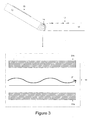
- the light which does not meet the conditions for total internal reflection escapes from the fibre 31, as illustrated schematically in Figure 5 by arrows A. In consequence, the light not meeting the conditions for total internal reflection is not detected by the photo-diode 42.
- the optical power detected by the photo-diode 42 is a function of the radius of the bend in the optical fibre 31 and, therefore, is also a function of the position of the hinge joint 14.
- the optical power detected at the photodiode 42 can be used to calculate the position of the hinge joint 14. Information concerning the position of the hinge joint 14 may then be processed to determine whether the handset 11 is open or closed and, accordingly, may be used to control the operational mode of the handset 11.
- the laser 41 and the photo-diode 42 are coupled to the controller 28, which is adapted to control the operational mode of the components of the handset 11 in dependence of the optical power level detected by the photodiode 42.
- These components may include, for example, the user display 15 and loudspeaker 16. Accordingly, if the optical power level detected by the photo-diode 42 falls below a predetermined threshold, the handset is determined to be closed and the operational mode of the lid 13 is switched to a power-saving mode. Alternatively, the optical power level may be used to monitor the precise angle of the hinge and may be used for more complex control of the handset 11.
- the laser 41 is comprised as part of the lid 13 and is coupled to the lid-end of the optical fibre 31.
- the photo-diode 42 is comprised as part of the base and is coupled to the base-end of the optical fibre 31.
- Light transmitted through the optical fibre 31 may carry control signals for controlling the operation of the handset 11.
- the user display 15 may be a touch-sensitive display and may be operated by a user to select menu options from the display for operating the handset 11.
- the control signals transmitted through the optical fibre 31 may comprise, for example, information concerning a menu option selected by a user touching the display 15. This information may then be relayed to the micro-controller 28 and used for controlling the operation of the handset 11.
- the photo-diode 42 is configured to detect the optical power received from the laser 41. Information concerning the optical power level detected at the base-end of the optical fibre 31 by the photo-diode 42 is supplied to the micro-controller 28 for controlling the operational mode of the handset 11. If the detected optical power level falls below the predetermined threshold value previously described, the handset 11 is determined to be closed and the micro-controller 28 switches the operational mode of the handset 11 to a power-saving mode. Alternatively, optical power level information supplied by the photo-diode 42 may be processed to control the operation of one or more components of the handset 11 directly.
- the optical power level detected by the photo-diode 42 is compared against a predetermined threshold value in order to determine whether the handset 11 is in the open or closed position. If the handset 11 is determined by the hinge-position detection apparatus to be in a closed position, the components of the handset 11 are configured to operate in a power saving mode. The handset 11 is thus able to increase the efficiency of its use of power and, accordingly, is able extend the standby time provided by a single charge of its battery (not shown).
- a second light detector for example a second photodiode 61, is located in the hinge joint 14 of the handset 11 to detect light escaping from the optical fibre 31.
- the second photodiode 61 is positioned in the area of maximum light emission from the bend in the optical fibre 31 to maximise the efficiency of detection of the light escaping from the fibre 31.
- the second photodiode 61 is coupled to the micro-controller 28 such that information concerning the power of the optical light escaping from the fibre 31 may be relayed back to the controller 28 and processed to determine whether the handset 11 is in the open or closed position.
- the photodiode 61 may be configured to communicate the detected power level back to the controller 28 by wireless means, for example via a Bluetooth connection.
- the optical power level detected by the photo-diode 61 is inversely proportional to the radius of the hinge joint 14; as the radius of the bend in the optical fibre 31 decreases, the optical power level detected by the photo-diode 61 increases.
- the apparatus By sensing the emitted light directly, the apparatus is able minimise the effect of errors due to losses caused by temperature fluctuations and aging of the optical fibre 31.
- the relationship between the power level detected by the photo-diode 61 and the radius in the bend of the optical fibre 31 may be used to provide detailed information regarding the position of the hinge joint 14.
- the optical power level detected by the photo-diode 61 may be used for calculating the angle of the hinge joint 14.
- the handset may comprise a different type of photo-sensitive device such as a photo-transistor or photo-resistor.
- the controller 28 processes the optical power level information supplied by the photo-diode 61 to control the operational mode of the handset 11. If the optical power level detected by the photo-diode 61 increases above a predetermined threshold value, the handset 11 is determined to be closed and the micro-controller 28 switches the operational mode of the handset 11 to a power saving mode. Alternatively, the optical power level detected by the photo-diode 61 may be used to control the operational mode of one or more individual components of the handset 11 directly.
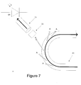
- the second photo-diode 61 is comprised as part of the base 12 of the handset 11 and a second optical wave-guide, for example a second optical fibre 71, is positioned to receive light escaping from the bend in the first optical fibre 31 and to direct the light.
- the handset may comprise alternative means for directing the light.
- the alternative means may comprise, for example, a light pipe comprising a length of plastic without cladding in which the plastic/air interface confines light to the light pipe.
- the optical fibre 71, optical wave-guide or light pipe may be used either with or without a light-collecting apparatus 72, for example comprising lenses, for collecting light escaping from the optical fibre 31.
- the light inlet to the optical fibre 71 is positioned adjacent to the point of maximum emission of the first optical fibre 31 during bending thereof.
- the optical power level detected by the photo-diode 61 is used, either by the controller 28 or directly, to control the operational mode of the handset 11. If the optical power level detected by the photo-diode 61 increases above a predetermined threshold, the handset 11 is determined to be closed and the handset 11 is switched to a power saving mode.
- the photo-diode 61 may be positioned at a convenient position in the base 12 of the handset 11. Alternatively, the photo-diode 61 may be positioned in the lid 13 of the handset 11.
- the optical fibre 31 may be surrounded by a protective jacket (not shown).
- a protective jacket (not shown).
- the jacket is removed at the point of maximum emission in order to allow the photo-diode 61 to detect the power level of the light escaping from the fibre 31.
- the protective jacket may be adapted such that the laser light is partially transmitted through the jacket. In this case, there is no need to remove the jacket in order for the photo-diode 61 to detect the light.
- the control of the operational mode of the handset 11 has been described as being dependent on a detected power level of light at a photo-diode. However, the control of the handset could equally be dependent on a calculated signal-loss.
- the implementation of the described hinge position detection apparatus involves minimal adaptation of the hardware of the handset 11.
- the components used for detection of the hinge's position are largely already present in many otherwise conventional mobile telephone handsets. Furthermore, apart from the optical fibre 31, no moving parts are used and, thus, the hinge-position detection apparatus can be considered to be extremely reliable.
- the hinge-position detection apparatus is not sensitive to electric or magnetic fields and will also not interfere with surrounding equipment, for example a GPS system, making use of such fields.
- hinge-position detection apparatus has been described with reference to a mobile telephone handset 11, the system is equally applicable to other types of electronic device which include a hinge section. These types of device include, for example, hand-held and lap-top computers, hand-held video games and personal digital assistants.
Landscapes
- Engineering & Computer Science (AREA)
- Physics & Mathematics (AREA)
- Computer Hardware Design (AREA)
- Theoretical Computer Science (AREA)
- General Physics & Mathematics (AREA)
- Human Computer Interaction (AREA)
- General Engineering & Computer Science (AREA)
- Signal Processing (AREA)
- Mathematical Physics (AREA)
- Optics & Photonics (AREA)
- Computer Networks & Wireless Communication (AREA)
- Telephone Set Structure (AREA)
- Optical Couplings Of Light Guides (AREA)
- Mechanical Coupling Of Light Guides (AREA)
- Optical Transform (AREA)
- Length Measuring Devices By Optical Means (AREA)
- Telephone Function (AREA)
Applications Claiming Priority (1)
| Application Number | Priority Date | Filing Date | Title |
|---|---|---|---|
| US11/423,927 US7415173B2 (en) | 2006-06-13 | 2006-06-13 | Position sensor |
Publications (2)
| Publication Number | Publication Date |
|---|---|
| EP1867958A2 true EP1867958A2 (de) | 2007-12-19 |
| EP1867958A3 EP1867958A3 (de) | 2010-06-23 |
Family
ID=38515496
Family Applications (1)
| Application Number | Title | Priority Date | Filing Date |
|---|---|---|---|
| EP07107375A Withdrawn EP1867958A3 (de) | 2006-06-13 | 2007-05-02 | Positionssensor |
Country Status (4)
| Country | Link |
|---|---|
| US (2) | US7415173B2 (de) |
| EP (1) | EP1867958A3 (de) |
| KR (2) | KR100895987B1 (de) |
| CN (1) | CN101106777A (de) |
Cited By (5)
| Publication number | Priority date | Publication date | Assignee | Title |
|---|---|---|---|---|
| WO2012063069A1 (en) * | 2010-11-10 | 2012-05-18 | Jt Consultancy Limited | A simulator including a controller |
| US20120154288A1 (en) * | 2010-12-17 | 2012-06-21 | Research In Motion Limited | Portable electronic device having a sensor arrangement for gesture recognition |
| WO2016146319A1 (de) * | 2015-03-15 | 2016-09-22 | Waldner Ag | Wägeabzug |
| WO2018026611A1 (en) * | 2016-08-04 | 2018-02-08 | Microsoft Technology Licensing, Llc | Folding angle sensing of a foldable device |
| RU2688596C1 (ru) * | 2018-07-02 | 2019-05-21 | федеральное государственное автономное образовательное учреждение высшего образования "Самарский национальный исследовательский университет имени академика С.П. Королёва" | Волоконно-оптический датчик угла поворота |
Families Citing this family (79)
| Publication number | Priority date | Publication date | Assignee | Title |
|---|---|---|---|---|
| US7532809B2 (en) * | 2002-06-25 | 2009-05-12 | International Business Machines Corporation | Personal video recording with pools and groups |
| GB0718706D0 (en) | 2007-09-25 | 2007-11-07 | Creative Physics Ltd | Method and apparatus for reducing laser speckle |
| US20080084539A1 (en) * | 2006-10-06 | 2008-04-10 | Daniel Tyler J | Human-machine interface device and method |
| US7873279B2 (en) * | 2007-01-11 | 2011-01-18 | Motorola Mobility, Inc. | Light transfer apparatus for an electronic device |
| US20080191904A1 (en) * | 2007-02-12 | 2008-08-14 | Kai-Jie Tsao | Method For Manufacturing Thin Keypad Assembly And Such Assembly |
| US8224137B2 (en) | 2007-10-11 | 2012-07-17 | Motorola Mobility, Inc. | Apparatus with two housings including a rotatable optical data communication coupling |
| US8843948B2 (en) * | 2008-09-19 | 2014-09-23 | The Nielsen Company (Us), Llc | Methods and apparatus to detect carrying of a portable audience measurement device |
| US8040237B2 (en) | 2008-10-29 | 2011-10-18 | The Nielsen Company (Us), Llc | Methods and apparatus to detect carrying of a portable audience measurement device |
| US11726332B2 (en) | 2009-04-27 | 2023-08-15 | Digilens Inc. | Diffractive projection apparatus |
| US9335604B2 (en) | 2013-12-11 | 2016-05-10 | Milan Momcilo Popovich | Holographic waveguide display |
| US11320571B2 (en) | 2012-11-16 | 2022-05-03 | Rockwell Collins, Inc. | Transparent waveguide display providing upper and lower fields of view with uniform light extraction |
| US10795160B1 (en) | 2014-09-25 | 2020-10-06 | Rockwell Collins, Inc. | Systems for and methods of using fold gratings for dual axis expansion |
| US11300795B1 (en) | 2009-09-30 | 2022-04-12 | Digilens Inc. | Systems for and methods of using fold gratings coordinated with output couplers for dual axis expansion |
| US8233204B1 (en) | 2009-09-30 | 2012-07-31 | Rockwell Collins, Inc. | Optical displays |
| US8659826B1 (en) | 2010-02-04 | 2014-02-25 | Rockwell Collins, Inc. | Worn display system and method without requiring real time tracking for boresight precision |
| US8704427B2 (en) | 2010-04-02 | 2014-04-22 | Sony Corporation | Movement sensor |
| US20120068846A1 (en) * | 2010-09-20 | 2012-03-22 | Honeywell International Inc. | Tamper event detection |
| JP5724439B2 (ja) * | 2011-02-18 | 2015-05-27 | ソニー株式会社 | 電子機器及び電子機器に搭載されるモジュール |
| US9274349B2 (en) | 2011-04-07 | 2016-03-01 | Digilens Inc. | Laser despeckler based on angular diversity |
| WO2016020630A2 (en) | 2014-08-08 | 2016-02-11 | Milan Momcilo Popovich | Waveguide laser illuminator incorporating a despeckler |
| US10670876B2 (en) | 2011-08-24 | 2020-06-02 | Digilens Inc. | Waveguide laser illuminator incorporating a despeckler |
| EP2748670B1 (de) | 2011-08-24 | 2015-11-18 | Rockwell Collins, Inc. | Tragbare datenanzeige |
| US9715067B1 (en) | 2011-09-30 | 2017-07-25 | Rockwell Collins, Inc. | Ultra-compact HUD utilizing waveguide pupil expander with surface relief gratings in high refractive index materials |
| US9507150B1 (en) | 2011-09-30 | 2016-11-29 | Rockwell Collins, Inc. | Head up display (HUD) using a bent waveguide assembly |
| US9366864B1 (en) | 2011-09-30 | 2016-06-14 | Rockwell Collins, Inc. | System for and method of displaying information without need for a combiner alignment detector |
| US8634139B1 (en) | 2011-09-30 | 2014-01-21 | Rockwell Collins, Inc. | System for and method of catadioptric collimation in a compact head up display (HUD) |
| US20150010265A1 (en) | 2012-01-06 | 2015-01-08 | Milan, Momcilo POPOVICH | Contact image sensor using switchable bragg gratings |
| US9523852B1 (en) | 2012-03-28 | 2016-12-20 | Rockwell Collins, Inc. | Micro collimator system and method for a head up display (HUD) |
| EP2842003B1 (de) | 2012-04-25 | 2019-02-27 | Rockwell Collins, Inc. | Holographisches weitwinkeldisplay |
| US9933684B2 (en) | 2012-11-16 | 2018-04-03 | Rockwell Collins, Inc. | Transparent waveguide display providing upper and lower fields of view having a specific light output aperture configuration |
| KR102058369B1 (ko) * | 2013-01-29 | 2019-12-24 | 엘지전자 주식회사 | 이동 단말기 및 이동 단말기용 커버 |
| US9348362B2 (en) * | 2013-02-08 | 2016-05-24 | Samsung Electronics Co., Ltd. | Flexible portable terminal |
| US9118356B2 (en) * | 2013-02-19 | 2015-08-25 | Apple Inc. | Data transport in portable electronic devices |
| US9674413B1 (en) | 2013-04-17 | 2017-06-06 | Rockwell Collins, Inc. | Vision system and method having improved performance and solar mitigation |
| US9727772B2 (en) | 2013-07-31 | 2017-08-08 | Digilens, Inc. | Method and apparatus for contact image sensing |
| US9244281B1 (en) | 2013-09-26 | 2016-01-26 | Rockwell Collins, Inc. | Display system and method using a detached combiner |
| US10732407B1 (en) | 2014-01-10 | 2020-08-04 | Rockwell Collins, Inc. | Near eye head up display system and method with fixed combiner |
| US9519089B1 (en) | 2014-01-30 | 2016-12-13 | Rockwell Collins, Inc. | High performance volume phase gratings |
| US9244280B1 (en) | 2014-03-25 | 2016-01-26 | Rockwell Collins, Inc. | Near eye display system and method for display enhancement or redundancy |
| US10571972B2 (en) * | 2014-03-28 | 2020-02-25 | Intel Corporation | Rotation sensor device |
| US9353560B2 (en) | 2014-06-27 | 2016-05-31 | Intel Corporatin | Smart variable torque display |
| WO2016020632A1 (en) | 2014-08-08 | 2016-02-11 | Milan Momcilo Popovich | Method for holographic mastering and replication |
| WO2016042283A1 (en) | 2014-09-19 | 2016-03-24 | Milan Momcilo Popovich | Method and apparatus for generating input images for holographic waveguide displays |
| US9715110B1 (en) | 2014-09-25 | 2017-07-25 | Rockwell Collins, Inc. | Automotive head up display (HUD) |
| US10088675B1 (en) | 2015-05-18 | 2018-10-02 | Rockwell Collins, Inc. | Turning light pipe for a pupil expansion system and method |
| US10437064B2 (en) | 2015-01-12 | 2019-10-08 | Digilens Inc. | Environmentally isolated waveguide display |
| US9632226B2 (en) | 2015-02-12 | 2017-04-25 | Digilens Inc. | Waveguide grating device |
| US10126552B2 (en) | 2015-05-18 | 2018-11-13 | Rockwell Collins, Inc. | Micro collimator system and method for a head up display (HUD) |
| US11366316B2 (en) | 2015-05-18 | 2022-06-21 | Rockwell Collins, Inc. | Head up display (HUD) using a light pipe |
| US10247943B1 (en) | 2015-05-18 | 2019-04-02 | Rockwell Collins, Inc. | Head up display (HUD) using a light pipe |
| US10108010B2 (en) | 2015-06-29 | 2018-10-23 | Rockwell Collins, Inc. | System for and method of integrating head up displays and head down displays |
| WO2017060665A1 (en) | 2015-10-05 | 2017-04-13 | Milan Momcilo Popovich | Waveguide display |
| US10598932B1 (en) | 2016-01-06 | 2020-03-24 | Rockwell Collins, Inc. | Head up display for integrating views of conformally mapped symbols and a fixed image source |
| KR20170088565A (ko) * | 2016-01-25 | 2017-08-02 | 삼성전자주식회사 | 휴대용 전자 장치의 보호용 케이스 및 케이스의 상태 판단 방법 |
| JP6895451B2 (ja) | 2016-03-24 | 2021-06-30 | ディジレンズ インコーポレイテッド | 偏光選択ホログラフィー導波管デバイスを提供するための方法および装置 |
| EP3433658B1 (de) | 2016-04-11 | 2023-08-09 | DigiLens, Inc. | Holographische wellenleitervorrichtung für die projektion von strukturiertem licht |
| EP3548939A4 (de) | 2016-12-02 | 2020-11-25 | DigiLens Inc. | Wellenleitervorrichtung mit gleichmässiger ausgabebeleuchtung |
| US10545346B2 (en) | 2017-01-05 | 2020-01-28 | Digilens Inc. | Wearable heads up displays |
| US10295824B2 (en) | 2017-01-26 | 2019-05-21 | Rockwell Collins, Inc. | Head up display with an angled light pipe |
| US10488898B2 (en) * | 2017-03-31 | 2019-11-26 | Microsoft Technology Licensing, Llc | Flexible heat spreader |
| CN111386495B (zh) | 2017-10-16 | 2022-12-09 | 迪吉伦斯公司 | 用于倍增像素化显示器的图像分辨率的系统和方法 |
| KR20190064964A (ko) * | 2017-12-01 | 2019-06-11 | 삼성전자주식회사 | 마이크로 스케일의 도파관 분광기 |
| US10753773B2 (en) * | 2017-12-21 | 2020-08-25 | Dell Products L.P. | Display device relative angle detection system |
| CN114721242B (zh) | 2018-01-08 | 2025-08-15 | 迪吉伦斯公司 | 用于制造光学波导的方法 |
| WO2019136476A1 (en) | 2018-01-08 | 2019-07-11 | Digilens, Inc. | Waveguide architectures and related methods of manufacturing |
| JP7404243B2 (ja) | 2018-01-08 | 2023-12-25 | ディジレンズ インコーポレイテッド | 導波管セル内のホログラフィック格子の高スループット記録のためのシステムおよび方法 |
| JP7456929B2 (ja) | 2018-01-08 | 2024-03-27 | ディジレンズ インコーポレイテッド | 導波管セルを製造するためのシステムおよび方法 |
| US11402801B2 (en) | 2018-07-25 | 2022-08-02 | Digilens Inc. | Systems and methods for fabricating a multilayer optical structure |
| US10642318B1 (en) * | 2018-09-14 | 2020-05-05 | Apple Inc. | Planar hinge assembly |
| WO2020149956A1 (en) | 2019-01-14 | 2020-07-23 | Digilens Inc. | Holographic waveguide display with light control layer |
| US20200247017A1 (en) | 2019-02-05 | 2020-08-06 | Digilens Inc. | Methods for Compensating for Optical Surface Nonuniformity |
| US20220283377A1 (en) | 2019-02-15 | 2022-09-08 | Digilens Inc. | Wide Angle Waveguide Display |
| EP3924759B1 (de) | 2019-02-15 | 2025-07-30 | Digilens Inc. | Verfahren und vorrichtungen zur herstellung einer holografischen wellenleiteranzeige mit integrierten gittern |
| JP2022525165A (ja) | 2019-03-12 | 2022-05-11 | ディジレンズ インコーポレイテッド | ホログラフィック導波管バックライトおよび関連する製造方法 |
| EP3980825A4 (de) | 2019-06-07 | 2023-05-03 | Digilens Inc. | Wellenleiter mit durchlässigen und reflektierenden gittern sowie zugehörige herstellungsverfahren |
| JP2022543571A (ja) | 2019-07-29 | 2022-10-13 | ディジレンズ インコーポレイテッド | 画素化されたディスプレイの画像解像度および視野を乗算するための方法および装置 |
| JP2022546413A (ja) | 2019-08-29 | 2022-11-04 | ディジレンズ インコーポレイテッド | 真空回折格子および製造方法 |
| WO2022150841A1 (en) | 2021-01-07 | 2022-07-14 | Digilens Inc. | Grating structures for color waveguides |
| KR20230153459A (ko) | 2021-03-05 | 2023-11-06 | 디지렌즈 인코포레이티드. | 진공 주기적 구조체 및 제조 방법 |
Citations (4)
| Publication number | Priority date | Publication date | Assignee | Title |
|---|---|---|---|---|
| US4633079A (en) | 1985-06-27 | 1986-12-30 | The United States Of America As Represented By The Secretary Of The Navy | Fiber optics as an angular sensor |
| US5321257A (en) | 1991-07-31 | 1994-06-14 | Danisch Lee A | Fiber optic bending and positioning sensor including a light emission surface formed on a portion of a light guide |
| US20020002929A1 (en) | 2000-02-22 | 2002-01-10 | 3M Innovative Properties Company | Durable fluorescent organic pigments and methods of making |
| FR2828277A1 (fr) | 2001-08-03 | 2003-02-07 | Renault | Capteur de position angulaire a fibre optique |
Family Cites Families (6)
| Publication number | Priority date | Publication date | Assignee | Title |
|---|---|---|---|---|
| US5097252A (en) * | 1987-03-24 | 1992-03-17 | Vpl Research Inc. | Motion sensor which produces an asymmetrical signal in response to symmetrical movement |
| US5089697A (en) * | 1989-01-11 | 1992-02-18 | Prohaska Otto J | Fiber optic sensing device including pressure detection and human implantable construction |
| DE4021269A1 (de) * | 1990-07-04 | 1992-01-09 | Ketterer Klaus | Verfahren und einrichtung zur ermittlung des verlaufes eines strebes im untertaegigen bergbau |
| US6571030B1 (en) * | 1999-11-02 | 2003-05-27 | Xros, Inc. | Optical cross-connect switching system |
| GB0021637D0 (en) * | 2000-09-04 | 2000-10-18 | Snap On Equipment Ltd | Method and apparatus for three-dimensional coordinate determination |
| JP2005286901A (ja) * | 2004-03-30 | 2005-10-13 | Japan Aviation Electronics Industry Ltd | 折りたたみ式携帯装置 |
-
2006
- 2006-06-13 US US11/423,927 patent/US7415173B2/en not_active Expired - Fee Related
-
2007
- 2007-05-02 EP EP07107375A patent/EP1867958A3/de not_active Withdrawn
- 2007-06-08 CN CNA2007101085882A patent/CN101106777A/zh active Pending
- 2007-06-12 KR KR1020070057451A patent/KR100895987B1/ko not_active Expired - Fee Related
-
2008
- 2008-06-24 KR KR1020080059834A patent/KR20080077055A/ko not_active Withdrawn
- 2008-07-18 US US12/175,727 patent/US20090026358A1/en not_active Abandoned
Patent Citations (4)
| Publication number | Priority date | Publication date | Assignee | Title |
|---|---|---|---|---|
| US4633079A (en) | 1985-06-27 | 1986-12-30 | The United States Of America As Represented By The Secretary Of The Navy | Fiber optics as an angular sensor |
| US5321257A (en) | 1991-07-31 | 1994-06-14 | Danisch Lee A | Fiber optic bending and positioning sensor including a light emission surface formed on a portion of a light guide |
| US20020002929A1 (en) | 2000-02-22 | 2002-01-10 | 3M Innovative Properties Company | Durable fluorescent organic pigments and methods of making |
| FR2828277A1 (fr) | 2001-08-03 | 2003-02-07 | Renault | Capteur de position angulaire a fibre optique |
Cited By (7)
| Publication number | Priority date | Publication date | Assignee | Title |
|---|---|---|---|---|
| WO2012063069A1 (en) * | 2010-11-10 | 2012-05-18 | Jt Consultancy Limited | A simulator including a controller |
| US20120154288A1 (en) * | 2010-12-17 | 2012-06-21 | Research In Motion Limited | Portable electronic device having a sensor arrangement for gesture recognition |
| US9569002B2 (en) * | 2010-12-17 | 2017-02-14 | Blackberry Limited | Portable electronic device having a sensor arrangement for gesture recognition |
| WO2016146319A1 (de) * | 2015-03-15 | 2016-09-22 | Waldner Ag | Wägeabzug |
| WO2018026611A1 (en) * | 2016-08-04 | 2018-02-08 | Microsoft Technology Licensing, Llc | Folding angle sensing of a foldable device |
| US10558277B2 (en) | 2016-08-04 | 2020-02-11 | Microsoft Technology Licensing, Llc | Folding angle sensing of a foldable device |
| RU2688596C1 (ru) * | 2018-07-02 | 2019-05-21 | федеральное государственное автономное образовательное учреждение высшего образования "Самарский национальный исследовательский университет имени академика С.П. Королёва" | Волоконно-оптический датчик угла поворота |
Also Published As
| Publication number | Publication date |
|---|---|
| CN101106777A (zh) | 2008-01-16 |
| KR20070118974A (ko) | 2007-12-18 |
| US7415173B2 (en) | 2008-08-19 |
| US20090026358A1 (en) | 2009-01-29 |
| KR20080077055A (ko) | 2008-08-21 |
| US20070286556A1 (en) | 2007-12-13 |
| KR100895987B1 (ko) | 2009-05-07 |
| EP1867958A3 (de) | 2010-06-23 |
Similar Documents
| Publication | Publication Date | Title |
|---|---|---|
| US7415173B2 (en) | Position sensor | |
| AU2018262947B2 (en) | Optical fingerprint verification method and mobile terminal | |
| CN102089989B (zh) | 控制射频蜂窝电话信号的发射功率的方法 | |
| US20020094789A1 (en) | Portable radio terminal device | |
| US20140113686A1 (en) | Method and apparatus for terminal to determine approach of object | |
| CN110798602A (zh) | 摄像模组、电子设备、拍摄控制方法及装置 | |
| CN107172348B (zh) | 移动终端及其运动信号的分发方法和装置 | |
| CN108683755A (zh) | 电子设备及显示装置 | |
| WO2018120240A1 (zh) | 一种调整电磁波辐射参数的装置、方法以及存储介质 | |
| KR102622026B1 (ko) | 안테나 임피던스를 매칭하기 위한 전자 장치 및 그의 동작 방법 | |
| CN103714316A (zh) | 图像识别方法、装置及电子设备 | |
| CN107704182A (zh) | 一种扫码方法及移动终端 | |
| KR102581412B1 (ko) | 다중 대역의 gnss 신호를 수신하기 위한 전자 장치 | |
| KR101695382B1 (ko) | 마우스 기능을 구비하는 케이스 | |
| CN107528958B (zh) | 移动终端控制方法、装置、可读存储介质和移动终端 | |
| CN115664453B (zh) | 射频电路、控制方法及装置、电子设备和可读存储介质 | |
| CN114122745B (zh) | 形态识别方法、电子设备及终端设备 | |
| KR100791117B1 (ko) | 알 에프 통신기기 제어장치 및 방법 | |
| EP1237286A1 (de) | Drahtlose kommunikationsvorrichtung | |
| KR100870504B1 (ko) | 개인휴대단말기용 광 포인팅 장치 | |
| CN111212158B (zh) | 终端设备 | |
| CN107231461A (zh) | 指纹的采集方法及相关产品 | |
| KR20110133143A (ko) | 통신 단말기의 동작 방법 및 장치 | |
| CN108259676B (zh) | 终端设备及感光控制方法 | |
| KR100790108B1 (ko) | 휴대단말기의 레이저 거리 측정 장치 |
Legal Events
| Date | Code | Title | Description |
|---|---|---|---|
| PUAI | Public reference made under article 153(3) epc to a published international application that has entered the european phase |
Free format text: ORIGINAL CODE: 0009012 |
|
| AK | Designated contracting states |
Kind code of ref document: A2 Designated state(s): AT BE BG CH CY CZ DE DK EE ES FI FR GB GR HU IE IS IT LI LT LU LV MC MT NL PL PT RO SE SI SK TR |
|
| AX | Request for extension of the european patent |
Extension state: AL BA HR MK YU |
|
| PUAL | Search report despatched |
Free format text: ORIGINAL CODE: 0009013 |
|
| AK | Designated contracting states |
Kind code of ref document: A3 Designated state(s): AT BE BG CH CY CZ DE DK EE ES FI FR GB GR HU IE IS IT LI LT LU LV MC MT NL PL PT RO SE SI SK TR |
|
| AX | Request for extension of the european patent |
Extension state: AL BA HR MK RS |
|
| 17P | Request for examination filed |
Effective date: 20101104 |
|
| AKX | Designation fees paid |
Designated state(s): AT BE BG CH CY CZ DE DK EE ES FI FR GB GR HU IE IS IT LI LT LU LV MC MT NL PL PT RO SE SI SK TR |
|
| STAA | Information on the status of an ep patent application or granted ep patent |
Free format text: STATUS: THE APPLICATION IS DEEMED TO BE WITHDRAWN |
|
| 18D | Application deemed to be withdrawn |
Effective date: 20111202 |