EP1867880A1 - Zylindereinheit mit Hubgeber - Google Patents
Zylindereinheit mit Hubgeber Download PDFInfo
- Publication number
- EP1867880A1 EP1867880A1 EP07008233A EP07008233A EP1867880A1 EP 1867880 A1 EP1867880 A1 EP 1867880A1 EP 07008233 A EP07008233 A EP 07008233A EP 07008233 A EP07008233 A EP 07008233A EP 1867880 A1 EP1867880 A1 EP 1867880A1
- Authority
- EP
- European Patent Office
- Prior art keywords
- magnet
- piston
- holder
- fluid pressure
- shock absorbing
- Prior art date
- Legal status (The legal status is an assumption and is not a legal conclusion. Google has not performed a legal analysis and makes no representation as to the accuracy of the status listed.)
- Granted
Links
Images

Classifications
-
- F—MECHANICAL ENGINEERING; LIGHTING; HEATING; WEAPONS; BLASTING
- F15—FLUID-PRESSURE ACTUATORS; HYDRAULICS OR PNEUMATICS IN GENERAL
- F15B—SYSTEMS ACTING BY MEANS OF FLUIDS IN GENERAL; FLUID-PRESSURE ACTUATORS, e.g. SERVOMOTORS; DETAILS OF FLUID-PRESSURE SYSTEMS, NOT OTHERWISE PROVIDED FOR
- F15B15/00—Fluid-actuated devices for displacing a member from one position to another; Gearing associated therewith
- F15B15/20—Other details, e.g. assembly with regulating devices
- F15B15/28—Means for indicating the position, e.g. end of stroke
- F15B15/2892—Means for indicating the position, e.g. end of stroke characterised by the attachment means
-
- F—MECHANICAL ENGINEERING; LIGHTING; HEATING; WEAPONS; BLASTING
- F15—FLUID-PRESSURE ACTUATORS; HYDRAULICS OR PNEUMATICS IN GENERAL
- F15B—SYSTEMS ACTING BY MEANS OF FLUIDS IN GENERAL; FLUID-PRESSURE ACTUATORS, e.g. SERVOMOTORS; DETAILS OF FLUID-PRESSURE SYSTEMS, NOT OTHERWISE PROVIDED FOR
- F15B15/00—Fluid-actuated devices for displacing a member from one position to another; Gearing associated therewith
- F15B15/20—Other details, e.g. assembly with regulating devices
- F15B15/28—Means for indicating the position, e.g. end of stroke
- F15B15/2815—Position sensing, i.e. means for continuous measurement of position, e.g. LVDT
- F15B15/2861—Position sensing, i.e. means for continuous measurement of position, e.g. LVDT using magnetic means
Definitions
- This invention relates to the installation of a stroke sensor in a fluid pressure cylinder.
- JPH11-190308A published by the Japan Patent Office in 1999 proposes a stroke sensor for detecting a stroke position of a fluid pressure cylinder.
- This stroke sensor comprises a sensor probe, a base of which is fixed to the cylinder and a tip of which is inserted into a bore formed axially in a piston rod through an opening formed in the central part of a piston.
- a magnetostrictive wire is built into the sensor probe in an axial direction.
- a pulsed electric current to the magnetostrictive wire, a magnetic field is formed on the outer circumference of the sensor probe in a circumferential direction.
- the magnetic field in the circumferential direction and a magnetic field formed by the magnet in the axial direction are integrated, and as a result a torsional strain in the magnetic field is generated in the position of the magnet. This phenomenon is known as the Wiedemann effect.
- the torsional strain in the magnetic field is transmitted as an acoustic wave along the magnetostrictive wire.
- the propagation period of this acoustic wave along the magnetostrictive wire has a linear relation with the distance from the magnet.
- the magnet is disposed in a recess formed in the central position of the piston.
- the opening of the recess faces the bottom of the cylinder.
- the magnet is gripped between a cap-shaped holder and a bottom of the recess.
- the holder is secured to the bottom of the recess by mounting screws.
- the axial position of the magnet may vary slightly. This variation causes a detection error in the stroke position. Further, if excessive torque is applied to the screws to secure the magnet firmly, the magnet may be damaged due to excessive tightening force.
- this invention provides a fluid pressure cylinder unit comprising, a cylinder, a piston housed in the cylinder so as to be free to slide in an axial direction, and a stroke sensor for detecting a relative position of the piston with respect to a cylinder.
- the stroke sensor comprises a magnet fixed to one of the cylinder and the piston, and a sensor probe fixed to the other of the cylinder and the piston.
- the sensor probe generates a signal in response to a relative position in the axial direction with respect to the magnet.
- the fluid pressure cylinder unit further comprises a shock absorbing member gripped between the magnet and the one of the cylinder and the piston.
- the shock absorbing member elastically deforms in the axial direction depending on a tightening force acting between the magnet and the one of the cylinder and the piston.
- FIG. 1 is a longitudinal sectional view of a hydraulic pressure cylinder unit according to this invention.
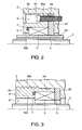
- FIG. 2 is an enlarged longitudinal sectional view of a magnet holding part of the hydraulic pressure cylinder unit.
- FIG. 3 is an enlarged longitudinal sectional view of a magnet holding part according to another embodiment of this invention.
- a hydraulic pressure cylinder unit comprises a cylinder 1, a piston 2a enclosed in the cylinder 1 so as to be free to slide, and a piston rod 2 connected to the piston 2a and projecting from the cylinder 1 in an axial direction.
- a hydraulic pressure chamber R is delimited in the cylinder 1 by the piston 2a.
- the hydraulic pressure chamber R drives the piston 2a in the axial direction within the cylinder 1 according to hydraulic pressure supplied from a hydraulic pressure source P disposed on the outside of the cylinder 1.
- the hydraulic pressure cylinder unit comprises a stroke sensor 100.
- the stroke sensor 100 comprises a sensor probe 3 fixed to the cylinder 1, and a magnet 4 fixed to the piston 2a.
- the sensor probe 3 is formed from a non-magnetic material.
- the sensor probe 3 penetrates a hole formed in a bottom cap member 11 which is fixed to a bottom 1a of the cylinder 1.
- a base portion 3b of the sensor probe 3 is screwed into the bottom cap member 11.
- the sensor probe 3 projects into the cylinder 1 and is covered by a sheath 32.
- the sheath 32 is made of a non-magnetic material and an end thereof is fitted into the hole in the bottom cap member 11.
- the sensor probe 3 penetrates a ring-shaped centering guide 33 which is fitted in the sheath 32, and is maintained in a state of concentricity with the sheath 32 thereby.
- a cylindrical recess A is formed in the central portion of the piston 2 facing the bottom 1a of the cylinder 1.
- a bore 2b connected to the recess A is formed in the piston rod 2 in the axial direction.
- the sensor probe 3 and the sheath 32 pass through the recess A and are inserted into the bore 2b.
- a centering guide 34 is fitted to the outer circumference of a tip of the sheath 32. The centering guide 34 is in contact with the inner circumference of the bore 2b so as to maintain the sheath 32 in a state of concentricity with the bore 2b.
- a magnetostrictive wire extending in the axial direction is enclosed in the sensor probe 3.
- a probe head 3a is fitted to the base of the sensor probe 3 so as to be exposed to the outside of the bottom cap member 11.
- a cable 3c is connected to the magnetostrictive wire via the probe head 3a so as to supply the magnetostrictive wire with a pulsed electric current.
- the magnet 4 is enclosed in the recess A.
- the magnet 4 is formed into a cylindrical shape that is long in the axial direction. It is also possible to construct the magnet 4 in a ring-shape or to construct the magnet 4 by accumulating ring-shaped magnet elements in the axial direction.
- the magnet 4 is enclosed in a cap-shaped holder 6 fixed to a bottom 2c of the recess A.
- the holder 6 is made of a non-magnetic material and provided with a through-hole through which the sheath 32 passes.
- the magnet 4 is arranged to face the outer circumference of the sheath 32 in the holder 6.
- An annular groove is formed on a bottom 62b of the holder 6, and a shock absorbing member 7 is fitted therein.
- a seat member 5 made of a non-magnetic material and having the same diameter as that of the recess A is fitted into the recess A so as to be in contact with the bottom 2c of the recess A.
- a flange 62a is formed at an opening of the holder 6. The diameter of the flange 62a is set in advance such that the outer circumference of the flange 62a comes into contact with the inner circumference 2d of the recess A.
- the holder 6 with the magnet 4 enclosed therein is fixed to the piston 2 by mounting screws 61 which penetrate bolt holes 5a formed in the flange 62a and the seat member 5 and are screwed into the piston 2.
- the shock absorbing member 7 is constituted by an O-ring made of a rubber material or a synthetic resin.
- the dimension of the shock absorbing member 7 are set such that the shock absorbing member 7 projects from the annular groove in the bottom 62b of the holder 6 towards the seat member 5.
- the holder 6 is temporarily fixed to the seat member 5 by, for example, an adhesive in advance, fitting the magnet 4 and the holder 6 into the recess A can be performed easily.
- the operation principle of the stroke sensor 100 is identical to that of the prior art.
- the magnet 4 is gripped between the seat member 5 and the shock absorbing member 7 supported by the bottom 62b of the holder 6. Deformation of the shock absorbing member 7 prevents excessive compression force from acting on the magnet 4 even when the tightening force of the mounting screws 61 is excessive, thereby protecting the magnet 4 from damage due to the excessive tightening force.
- the shock absorbing member 7 exerts a resilient force on the magnet 4 so as to keep the magnet 4 in contact with the seat member 5 even when the tightening force of the mounting screws 6 is insufficient. According to this invention, therefore, the magnet 4 is maintained in the predetermined position with high precision irrespective of the tightening force of the mounting screws 61.
- the entire holder 6 is formed into a cylindrical shape.
- a male screw 62c is formed on the outer circumference of the holder 62 and a female screw is formed on the inner circumference 2d of the recess A.
- deformation of the shock absorbing member 7 protects the magnet 4 from damage due to excessive tightening force while ensuring precise positioning of the magnet 4.
- the mounting screws 61 are omitted in this embodiment, and hence the number of components required for installing the stroke sensor 100 can be decreased.
- Tokugan 2006-166835 The contents of Tokugan 2006-166835, with a filing date of June 16, 2006 in Japan , are hereby incorporated by reference.
- the sensor probe 3 is fixed to the cylinder 1 while the magnet 4 is fixed to the piston 2a, but this invention can be applied to a fluid pressure sensor in which the magnet is fixed to the cylinder while the sensor probe is 'fixed to the piston.
- the shock absorbing member 7 is disposed in the annular groove formed on the bottom 62b of the holder 6, but the annular groove for accommodating the shock absorbing member 7 may be formed in the seat member 5.
- the hydraulic pressure cylinder is a single rod type, but this invention can be applied to a double rod type hydraulic pressure cylinder.
- This invention can be applied to any kind of hydraulic pressure cylinder including cylinder for seismic isolation of civil or architectural structures.
- the fluid pressure cylinder to which this invention is applied should not be limited to a hydraulic pressure cylinder.
- This invention can be also applied to an air pressure cylinder, for example.
Landscapes
- Engineering & Computer Science (AREA)
- Physics & Mathematics (AREA)
- Fluid Mechanics (AREA)
- Mechanical Engineering (AREA)
- General Engineering & Computer Science (AREA)
- Actuator (AREA)
- Measurement Of Length, Angles, Or The Like Using Electric Or Magnetic Means (AREA)
Applications Claiming Priority (1)
| Application Number | Priority Date | Filing Date | Title |
|---|---|---|---|
| JP2006166835A JP2007333122A (ja) | 2006-06-16 | 2006-06-16 | 油圧シリンダ |
Publications (2)
| Publication Number | Publication Date |
|---|---|
| EP1867880A1 true EP1867880A1 (de) | 2007-12-19 |
| EP1867880B1 EP1867880B1 (de) | 2009-06-17 |
Family
ID=38461053
Family Applications (1)
| Application Number | Title | Priority Date | Filing Date |
|---|---|---|---|
| EP20070008233 Expired - Fee Related EP1867880B1 (de) | 2006-06-16 | 2007-04-23 | Zylindereinheit mit Hubgeber |
Country Status (5)
| Country | Link |
|---|---|
| EP (1) | EP1867880B1 (de) |
| JP (1) | JP2007333122A (de) |
| CN (1) | CN100545466C (de) |
| DE (1) | DE602007001309D1 (de) |
| ES (1) | ES2326005T3 (de) |
Cited By (4)
| Publication number | Priority date | Publication date | Assignee | Title |
|---|---|---|---|---|
| US9334961B2 (en) | 2010-12-22 | 2016-05-10 | Knorr-Bremse Systeme Fuer Nutzfahrzeuge Gmbh | Cover for a cylinder arrangement, cylinder arrangement, and automatic transmission |
| WO2017097963A1 (fr) * | 2015-12-11 | 2017-06-15 | Valeo Embrayages | Dispositif de commande hydraulique |
| US11280409B2 (en) | 2016-08-10 | 2022-03-22 | Smc Corporation | Method for producing piston assembly and hydraulic fluid device |
| WO2022132517A1 (en) * | 2020-12-15 | 2022-06-23 | Caterpillar Inc. | Molded in magnetic sensor and systems, assemblies, components, and methods thereof |
Families Citing this family (17)
| Publication number | Priority date | Publication date | Assignee | Title |
|---|---|---|---|---|
| DE102009010132A1 (de) * | 2008-03-13 | 2009-09-17 | Luk Lamellen Und Kupplungsbau Beteiligungs Kg | Hydraulikzylinder mit Informationsgeber |
| CN101726327B (zh) * | 2008-10-17 | 2012-02-29 | 上海恒祥光学电子有限公司 | 旋转编码器的减震装置 |
| US8100045B2 (en) * | 2008-10-21 | 2012-01-24 | Clark Equipment Company | Hydraulic cylinder rod position sensor |
| WO2010133006A1 (en) * | 2009-05-20 | 2010-11-25 | Norgren, Inc. | Capacitive linear displacement sensor and cylinder device |
| CN102352896B (zh) * | 2011-09-21 | 2013-03-27 | 东风汽车有限公司 | 一种机械式自动变速器的离合器执行机构 |
| CN104395616B (zh) * | 2012-07-20 | 2016-08-17 | 博格华纳公司 | 内部位置传感器 |
| CN104132022B (zh) * | 2014-07-30 | 2016-08-31 | 湖北三江航天万山特种车辆有限公司 | 一种简易伺服油缸 |
| CN104165171B (zh) * | 2014-07-30 | 2017-10-13 | 三一重工股份有限公司 | 一种传感器保护装置、油缸及工程机械 |
| CN106224320A (zh) * | 2016-09-12 | 2016-12-14 | 天津大学 | 内置位移传感器集成式单出杆对称液压缸 |
| CN106369004B (zh) * | 2016-09-12 | 2018-03-13 | 天津大学 | 内置位移传感器集成式电机泵控单出杆对称液压缸 |
| CN107165888B (zh) * | 2017-07-07 | 2019-02-22 | 徐州徐工液压件有限公司 | 一种带位移传感器的液压缸模块化结构 |
| PT3428461T (pt) * | 2017-07-14 | 2021-04-27 | Hydraulique Production Systems | Cilindro hidráulico e instalação que implementa pelo menos um tal cilindro hidráulico |
| CN107654443B (zh) * | 2017-08-28 | 2024-02-06 | 无锡瑞真精机股份有限公司 | 伸缩式液压自定心机构 |
| DE102018202659A1 (de) * | 2018-02-22 | 2019-08-22 | Zf Friedrichshafen Ag | Dämpfungsanordnung für Leistungselektronikanwendungen |
| EP3620754B1 (de) * | 2018-09-06 | 2022-01-05 | KNORR-BREMSE Systeme für Nutzfahrzeuge GmbH | Magnethalter und hubsensor mit dem magnethalter |
| CN109578363B (zh) * | 2018-12-14 | 2020-10-27 | 中国航空工业集团公司金城南京机电液压工程研究中心 | 一种活塞杆内置位移传感器的柔性固定约束结构 |
| CN111043099B (zh) * | 2019-11-27 | 2021-08-03 | 北京航空航天大学 | 一种对称型数字液压缸 |
Citations (5)
| Publication number | Priority date | Publication date | Assignee | Title |
|---|---|---|---|---|
| AT392126B (de) * | 1989-01-12 | 1991-01-25 | Weber Oelhydraulik | Hydraulikzylinder |
| US5150049A (en) * | 1991-06-24 | 1992-09-22 | Schuetz Tool & Die, Inc. | Magnetostrictive linear displacement transducer with temperature compensation |
| DE29607993U1 (de) * | 1996-05-03 | 1996-08-01 | Festo Kg | Kolben für einen Arbeitszylinder |
| JPH11190308A (ja) * | 1997-12-25 | 1999-07-13 | Kayaba Ind Co Ltd | 伸縮位置検出構造 |
| EP1217220A2 (de) * | 2000-12-20 | 2002-06-26 | Caterpillar Inc. | Fluidzylinder mit integriertem Positionsensor |
Family Cites Families (7)
| Publication number | Priority date | Publication date | Assignee | Title |
|---|---|---|---|---|
| CN2055202U (zh) * | 1989-05-25 | 1990-03-28 | 成都华西化工研究所 | 位置传感式液压缸 |
| DE4122481C2 (de) * | 1991-07-06 | 1995-08-31 | Kuhnke Gmbh Kg H | Kolben-Zylinder-Anordnung |
| JPH07229704A (ja) * | 1994-02-22 | 1995-08-29 | Sumitomo Electric Ind Ltd | 移動量検出器 |
| DE4442019C2 (de) * | 1994-11-25 | 2003-07-31 | Integral Accumulator Kg | Stellungsüberwachter Kolbenspeicher |
| DE19740990C2 (de) * | 1997-09-18 | 2001-11-29 | Enidine Gmbh | Kolben-Zylinder-Anordnung |
| CN2539019Y (zh) * | 2002-04-26 | 2003-03-05 | 无锡市长江液压缸厂 | 一种带有线性位移传感器的高压重型液压缸 |
| CN2650062Y (zh) * | 2003-10-29 | 2004-10-20 | 宝山钢铁股份有限公司 | 密封式限位转换器 |
-
2006
- 2006-06-16 JP JP2006166835A patent/JP2007333122A/ja active Pending
-
2007
- 2007-04-23 ES ES07008233T patent/ES2326005T3/es active Active
- 2007-04-23 DE DE200760001309 patent/DE602007001309D1/de active Active
- 2007-04-23 EP EP20070008233 patent/EP1867880B1/de not_active Expired - Fee Related
- 2007-04-27 CN CN 200710097571 patent/CN100545466C/zh not_active Expired - Fee Related
Patent Citations (5)
| Publication number | Priority date | Publication date | Assignee | Title |
|---|---|---|---|---|
| AT392126B (de) * | 1989-01-12 | 1991-01-25 | Weber Oelhydraulik | Hydraulikzylinder |
| US5150049A (en) * | 1991-06-24 | 1992-09-22 | Schuetz Tool & Die, Inc. | Magnetostrictive linear displacement transducer with temperature compensation |
| DE29607993U1 (de) * | 1996-05-03 | 1996-08-01 | Festo Kg | Kolben für einen Arbeitszylinder |
| JPH11190308A (ja) * | 1997-12-25 | 1999-07-13 | Kayaba Ind Co Ltd | 伸縮位置検出構造 |
| EP1217220A2 (de) * | 2000-12-20 | 2002-06-26 | Caterpillar Inc. | Fluidzylinder mit integriertem Positionsensor |
Cited By (5)
| Publication number | Priority date | Publication date | Assignee | Title |
|---|---|---|---|---|
| US9334961B2 (en) | 2010-12-22 | 2016-05-10 | Knorr-Bremse Systeme Fuer Nutzfahrzeuge Gmbh | Cover for a cylinder arrangement, cylinder arrangement, and automatic transmission |
| WO2017097963A1 (fr) * | 2015-12-11 | 2017-06-15 | Valeo Embrayages | Dispositif de commande hydraulique |
| FR3045114A1 (fr) * | 2015-12-11 | 2017-06-16 | Valeo Embrayages | Dispositif de commande hydraulique |
| US11280409B2 (en) | 2016-08-10 | 2022-03-22 | Smc Corporation | Method for producing piston assembly and hydraulic fluid device |
| WO2022132517A1 (en) * | 2020-12-15 | 2022-06-23 | Caterpillar Inc. | Molded in magnetic sensor and systems, assemblies, components, and methods thereof |
Also Published As
| Publication number | Publication date |
|---|---|
| CN100545466C (zh) | 2009-09-30 |
| ES2326005T3 (es) | 2009-09-28 |
| DE602007001309D1 (de) | 2009-07-30 |
| JP2007333122A (ja) | 2007-12-27 |
| EP1867880B1 (de) | 2009-06-17 |
| CN101089406A (zh) | 2007-12-19 |
Similar Documents
| Publication | Publication Date | Title |
|---|---|---|
| EP1867880B1 (de) | Zylindereinheit mit Hubgeber | |
| EP2941576B1 (de) | Verbesserte lastenanzeigevorrichtung | |
| CA2029041C (en) | Piezoelectric pressure sensor | |
| EP2827117B1 (de) | Verbrennungsmotor mit verbrennungsdruckdetektor und verbrennungsdruckdetektor | |
| KR102202322B1 (ko) | 수동 조작 또는 공압 프레스용 힘 센서 | |
| US11105694B2 (en) | Torque sensor having a sealing membrane | |
| EP3285058B1 (de) | Drucksensor | |
| CN111678639B (zh) | 一种自由场压力传感器动态灵敏度系数标定装置 | |
| US10989588B2 (en) | Sensor device | |
| CN100385220C (zh) | 测定液压压力的压力传感器 | |
| US20190162219A1 (en) | Distance sensor at anchor tip | |
| US9339865B2 (en) | Electric drive for a processing tool such as a blind rivet setting appliance, processing tool and method for the closed-loop controlled setting of a rivet with such an electric drive | |
| JPH0820324B2 (ja) | 管状物体内の圧力を測定する方法および装置 | |
| JP2005338003A (ja) | 磁界形成デバイス及びこれを用いた変位センサ | |
| US20110056925A1 (en) | Pressure Measuring Glow Plug | |
| JP2020186950A (ja) | ボルト、及び、検出システム | |
| US20200263710A1 (en) | Bent sensor for position transducer | |
| WO2003081186A3 (en) | Vibration sensor having a flextensional body | |
| US8356511B2 (en) | Device including a pressure sensor for measuring pressures inside the combustion chamber of an engine | |
| US20210040965A1 (en) | Sensor unit for fluidic cylinder and fluidic cylinder | |
| US20040060363A1 (en) | Blind fastener setting tool | |
| WO2018003267A1 (ja) | 圧力センサ | |
| GB2050624A (en) | Strain transducers | |
| US20050126297A1 (en) | Pressure sensor element having an integrated sealing surface | |
| CN107478501B (zh) | 一种反射式霍普金森拉杆试样的保护装置及实验方法 |
Legal Events
| Date | Code | Title | Description |
|---|---|---|---|
| PUAI | Public reference made under article 153(3) epc to a published international application that has entered the european phase |
Free format text: ORIGINAL CODE: 0009012 |
|
| AK | Designated contracting states |
Kind code of ref document: A1 Designated state(s): AT BE BG CH CY CZ DE DK EE ES FI FR GB GR HU IE IS IT LI LT LU LV MC MT NL PL PT RO SE SI SK TR |
|
| AX | Request for extension of the european patent |
Extension state: AL BA HR MK YU |
|
| 17P | Request for examination filed |
Effective date: 20071214 |
|
| 17Q | First examination report despatched |
Effective date: 20080514 |
|
| AKX | Designation fees paid |
Designated state(s): DE ES GB IT |
|
| GRAP | Despatch of communication of intention to grant a patent |
Free format text: ORIGINAL CODE: EPIDOSNIGR1 |
|
| GRAS | Grant fee paid |
Free format text: ORIGINAL CODE: EPIDOSNIGR3 |
|
| GRAA | (expected) grant |
Free format text: ORIGINAL CODE: 0009210 |
|
| AK | Designated contracting states |
Kind code of ref document: B1 Designated state(s): DE ES GB IT |
|
| REG | Reference to a national code |
Ref country code: GB Ref legal event code: FG4D |
|
| REF | Corresponds to: |
Ref document number: 602007001309 Country of ref document: DE Date of ref document: 20090730 Kind code of ref document: P |
|
| REG | Reference to a national code |
Ref country code: ES Ref legal event code: FG2A Ref document number: 2326005 Country of ref document: ES Kind code of ref document: T3 |
|
| PLBE | No opposition filed within time limit |
Free format text: ORIGINAL CODE: 0009261 |
|
| STAA | Information on the status of an ep patent application or granted ep patent |
Free format text: STATUS: NO OPPOSITION FILED WITHIN TIME LIMIT |
|
| 26N | No opposition filed |
Effective date: 20100318 |
|
| PG25 | Lapsed in a contracting state [announced via postgrant information from national office to epo] |
Ref country code: IT Free format text: LAPSE BECAUSE OF NON-PAYMENT OF DUE FEES Effective date: 20100423 |
|
| REG | Reference to a national code |
Ref country code: DE Ref legal event code: R082 Ref document number: 602007001309 Country of ref document: DE Representative=s name: GRUENECKER PATENT- UND RECHTSANWAELTE PARTG MB, DE Ref country code: DE Ref legal event code: R081 Ref document number: 602007001309 Country of ref document: DE Owner name: KYB CORPORATION, JP Free format text: FORMER OWNER: KAYABA INDUSTRY CO., LTD., TOKYO, JP |
|
| REG | Reference to a national code |
Ref country code: ES Ref legal event code: PC2A Owner name: KYB CORPORATION Effective date: 20160226 |
|
| PGFP | Annual fee paid to national office [announced via postgrant information from national office to epo] |
Ref country code: ES Payment date: 20190521 Year of fee payment: 13 Ref country code: DE Payment date: 20190418 Year of fee payment: 13 Ref country code: IT Payment date: 20190429 Year of fee payment: 13 |
|
| PGFP | Annual fee paid to national office [announced via postgrant information from national office to epo] |
Ref country code: GB Payment date: 20190418 Year of fee payment: 13 |
|
| REG | Reference to a national code |
Ref country code: DE Ref legal event code: R119 Ref document number: 602007001309 Country of ref document: DE |
|
| PG25 | Lapsed in a contracting state [announced via postgrant information from national office to epo] |
Ref country code: DE Free format text: LAPSE BECAUSE OF NON-PAYMENT OF DUE FEES Effective date: 20201103 |
|
| GBPC | Gb: european patent ceased through non-payment of renewal fee |
Effective date: 20200423 |
|
| PG25 | Lapsed in a contracting state [announced via postgrant information from national office to epo] |
Ref country code: GB Free format text: LAPSE BECAUSE OF NON-PAYMENT OF DUE FEES Effective date: 20200423 |
|
| REG | Reference to a national code |
Ref country code: ES Ref legal event code: FD2A Effective date: 20210903 |
|
| PG25 | Lapsed in a contracting state [announced via postgrant information from national office to epo] |
Ref country code: ES Free format text: LAPSE BECAUSE OF NON-PAYMENT OF DUE FEES Effective date: 20200424 |
|
| PG25 | Lapsed in a contracting state [announced via postgrant information from national office to epo] |
Ref country code: IT Free format text: LAPSE BECAUSE OF NON-PAYMENT OF DUE FEES Effective date: 20200423 |