EP1867832B1 - Drosselventil zur Fluidinjektion in geologische Formationen - Google Patents
Drosselventil zur Fluidinjektion in geologische Formationen Download PDFInfo
- Publication number
- EP1867832B1 EP1867832B1 EP07010996A EP07010996A EP1867832B1 EP 1867832 B1 EP1867832 B1 EP 1867832B1 EP 07010996 A EP07010996 A EP 07010996A EP 07010996 A EP07010996 A EP 07010996A EP 1867832 B1 EP1867832 B1 EP 1867832B1
- Authority
- EP
- European Patent Office
- Prior art keywords
- throttle valve
- pressure
- valve
- fluid
- throttle
- Prior art date
- Legal status (The legal status is an assumption and is not a legal conclusion. Google has not performed a legal analysis and makes no representation as to the accuracy of the status listed.)
- Not-in-force
Links
- 238000002347 injection Methods 0.000 title claims abstract description 94
- 239000007924 injection Substances 0.000 title claims abstract description 94
- 239000012530 fluid Substances 0.000 title claims abstract description 89
- 230000015572 biosynthetic process Effects 0.000 title claims abstract description 32
- 238000005755 formation reaction Methods 0.000 title description 24
- CURLTUGMZLYLDI-UHFFFAOYSA-N Carbon dioxide Chemical compound O=C=O CURLTUGMZLYLDI-UHFFFAOYSA-N 0.000 claims abstract description 20
- 238000000034 method Methods 0.000 claims abstract description 17
- 239000007788 liquid Substances 0.000 claims abstract description 13
- 238000007789 sealing Methods 0.000 claims abstract description 13
- 229910002092 carbon dioxide Inorganic materials 0.000 claims abstract description 10
- 239000001569 carbon dioxide Substances 0.000 claims abstract description 10
- 210000002105 tongue Anatomy 0.000 claims description 4
- XLYOFNOQVPJJNP-UHFFFAOYSA-N water Substances O XLYOFNOQVPJJNP-UHFFFAOYSA-N 0.000 claims description 2
- 238000003780 insertion Methods 0.000 claims 3
- 230000037431 insertion Effects 0.000 claims 3
- 238000006073 displacement reaction Methods 0.000 description 4
- 230000001419 dependent effect Effects 0.000 description 3
- 239000011435 rock Substances 0.000 description 3
- 238000004891 communication Methods 0.000 description 2
- 238000010276 construction Methods 0.000 description 2
- 230000000694 effects Effects 0.000 description 2
- 238000012423 maintenance Methods 0.000 description 2
- VNWKTOKETHGBQD-UHFFFAOYSA-N methane Chemical compound C VNWKTOKETHGBQD-UHFFFAOYSA-N 0.000 description 2
- 230000003287 optical effect Effects 0.000 description 2
- 230000009467 reduction Effects 0.000 description 2
- 239000000243 solution Substances 0.000 description 2
- 230000009471 action Effects 0.000 description 1
- 239000000654 additive Substances 0.000 description 1
- 230000000996 additive effect Effects 0.000 description 1
- 230000005540 biological transmission Effects 0.000 description 1
- 230000008859 change Effects 0.000 description 1
- 239000004927 clay Substances 0.000 description 1
- 238000002485 combustion reaction Methods 0.000 description 1
- 238000007796 conventional method Methods 0.000 description 1
- 230000007797 corrosion Effects 0.000 description 1
- 238000005260 corrosion Methods 0.000 description 1
- 230000007423 decrease Effects 0.000 description 1
- 230000002401 inhibitory effect Effects 0.000 description 1
- 238000009434 installation Methods 0.000 description 1
- 230000010354 integration Effects 0.000 description 1
- 238000005259 measurement Methods 0.000 description 1
- 239000003345 natural gas Substances 0.000 description 1
- 230000035699 permeability Effects 0.000 description 1
- 239000011148 porous material Substances 0.000 description 1
- 238000012545 processing Methods 0.000 description 1
- 150000003839 salts Chemical class 0.000 description 1
- 238000000926 separation method Methods 0.000 description 1
- 230000035939 shock Effects 0.000 description 1
Images


Classifications
-
- E—FIXED CONSTRUCTIONS
- E21—EARTH OR ROCK DRILLING; MINING
- E21B—EARTH OR ROCK DRILLING; OBTAINING OIL, GAS, WATER, SOLUBLE OR MELTABLE MATERIALS OR A SLURRY OF MINERALS FROM WELLS
- E21B34/00—Valve arrangements for boreholes or wells
- E21B34/06—Valve arrangements for boreholes or wells in wells
-
- E—FIXED CONSTRUCTIONS
- E21—EARTH OR ROCK DRILLING; MINING
- E21B—EARTH OR ROCK DRILLING; OBTAINING OIL, GAS, WATER, SOLUBLE OR MELTABLE MATERIALS OR A SLURRY OF MINERALS FROM WELLS
- E21B41/00—Equipment or details not covered by groups E21B15/00 - E21B40/00
- E21B41/005—Waste disposal systems
- E21B41/0057—Disposal of a fluid by injection into a subterranean formation
- E21B41/0064—Carbon dioxide sequestration
-
- E—FIXED CONSTRUCTIONS
- E21—EARTH OR ROCK DRILLING; MINING
- E21B—EARTH OR ROCK DRILLING; OBTAINING OIL, GAS, WATER, SOLUBLE OR MELTABLE MATERIALS OR A SLURRY OF MINERALS FROM WELLS
- E21B43/00—Methods or apparatus for obtaining oil, gas, water, soluble or meltable materials or a slurry of minerals from wells
- E21B43/12—Methods or apparatus for controlling the flow of the obtained fluid to or in wells
-
- Y—GENERAL TAGGING OF NEW TECHNOLOGICAL DEVELOPMENTS; GENERAL TAGGING OF CROSS-SECTIONAL TECHNOLOGIES SPANNING OVER SEVERAL SECTIONS OF THE IPC; TECHNICAL SUBJECTS COVERED BY FORMER USPC CROSS-REFERENCE ART COLLECTIONS [XRACs] AND DIGESTS
- Y02—TECHNOLOGIES OR APPLICATIONS FOR MITIGATION OR ADAPTATION AGAINST CLIMATE CHANGE
- Y02C—CAPTURE, STORAGE, SEQUESTRATION OR DISPOSAL OF GREENHOUSE GASES [GHG]
- Y02C20/00—Capture or disposal of greenhouse gases
- Y02C20/40—Capture or disposal of greenhouse gases of CO2
Definitions
- the invention relates to a throttle valve according to the preamble of claim 1, a fluid injection device equipped with such a throttle valve, for injecting a fluid into a geological formation, and a method for injecting a fluid into a geological formation.
- the invention also relates to methods for assembling and disassembling the throttle valve in an injection pipe string.
- CO 2 carbon dioxide
- the storage of carbon dioxide is typically via an injection tube, which extends into the geological formation.
- the injection tube is arranged in a bore which is cased and cemented down to the lower region.
- the pipes are subsequently perforated in selected areas. From the end of the injection tube, the CO 2 is to be filled in a large area in the pores of the rock of the geological formation.
- the injection of CO 2 is provided in the liquid state.
- a density of about 0.7 kg / dm 3 and the required liquefaction pressure for CO 2 at the feed (about 65 bar) at the lowest end of the borehole (about 800 m) by the pressure of liquid CO 2, the ambient pressure significantly exceeded in the geological formation.
- the high overpressure threatens an undesirable change of the rock by cracks, which also the covering layer (eg clay or Salt) above the storing formation. There is therefore an interest in reducing the pressure of the liquid CO 2 in the borehole through a throttle valve.
- Valves can be differentiated according to the shut-off properties, the control properties, the type of drive, the medium flowing through or the area of application. For example, are off EP 1 035 360 .
- US 5 535 983 and WO 92/03676 Pinch valves are known in which a hose-like portion is reduced by an external radial pressure in cross section. Although a reliable closing function can be realized with the pinch valves, disadvantages can result from limited control properties.
- DE 36 85 640 T2 An underground sliding sleeve valve and its mounting in a pipe are described.
- EP 0 986 690 B1 a well valve with a selectively movable valve element is known.
- DE 696 29 973 discloses a remote controlled valve with movable spool, which is activated by means of liquid. These conventional valves have disadvantages by a complex structure and a limited reliability.
- a throttle valve is off US 3,381,708 also known.
- a sleeve valve in which the closed state is dependent on the position of a cylindrical sleeve relative to a valve plate.
- the sleeve is connected to an annular piston which is slidably mounted in a cylinder. By loading the cylinder with a pressure medium of the annular piston can be moved and thus the sleeve valve can be actuated.
- the sleeve valve according to DE 25 49 113 Due to its complex structure and the limited ability to precisely adjustable pressure reduction, especially under high pressure conditions, considerable disadvantages an application in geotechnical tasks and in particular in the injection of CO 2 is excluded.
- the conventional valves further have at least one of the following disadvantages.
- Another disadvantage is significant limitations in the maintenance and interchangeability of conventional valves.
- the object of the invention is to provide an improved throttle valve, in particular for the injection of a fluid in an underground storage, with which the disadvantages of the conventional throttle valves are avoided.
- the object of the invention is further to provide an improved fluid injection device which avoids the disadvantages and limitations of conventional techniques for fluid injection into underground reservoirs.
- the object of the invention is also to provide an improved method for injecting a fluid into a subterranean reservoir, in particular into a geological formation.
- the invention according to a first aspect is based on the general technical teaching of providing a throttle valve with a fluid channel which is part of a ring piston displaceable by pressurization.
- the Fluid channel provides a closable and controllable connection between a high pressure side and a low pressure side of the throttle valve.
- the fluid channel On the low pressure side, the fluid channel has an open end.
- an end closed in the longitudinal direction (axial direction) of the throttle valve with a laterally projecting sealing plate and a lateral (radial) throttle opening are provided.
- the fluid channel can be positioned so that the sealing plate is tightly seated on a cover plate provided on the high pressure side (closed state) or the lateral throttle opening is released (controllable passage state).
- the lateral throttle opening of the fluid channel interacts with the cover plate of the throttle valve in such a way that, in the on-state, depending on the setting of the annular piston with the cover plate, a part of the throttle opening is covered or the throttle opening is completely released.
- the throttle valve has a compact, adapted to the geometric conditions downhole construction with a high pressure resistance, wherein the provision of the sealing plate and the lateral throttle opening, the closing and passage functions of the throttle valve are optimized separately.
- the throttle valve simultaneously fulfills a reliable closing function and a precise, controllable opening in the on-state, so that with high reliability and safety liquid fluids, in particular liquid CO 2 at the permissible injection pressure in a geological formation can be inserted.
- the throttle opening has a geometric shape (throttle contour) with an extension in the longitudinal direction towards the low pressure side of the throttle valve, z. B. on a triangular shape.
- the passage function of the throttle valve receives a characteristic, non-linear characteristic.
- the annular piston of the piston valve according to the invention is arranged in a piston chamber which has a high pressure side and a low pressure side annular space on both sides of the annular piston.
- the low-pressure side annular space is provided to be acted upon for actuating the throttle valve with a working pressure.
- the fluid channel according to the invention has a lateral connection opening through which the fluid channel is connected to the high-pressure side annular space.
- a throttle line is preferably provided, via which a connection of the low-pressure-side annular space with the environment can be formed.
- a single throttle line through the valve body of the throttle valve is sufficient, so that the compact and stable construction of the throttle valve is not affected.
- the reliability is improved with the throttle line. If, for example, an undesirable pressure drop occurs, this fault leads to the automatic closing of the throttle valve. Even if the pressure drops abruptly, is avoided by the throttle function of the throttle line a pressure shock at the throttle valve.
- the valve body of the throttle valve may have a radially symmetrical external shape relative to the longitudinal extent of the piston chamber.
- seals are provided on the surface of the valve body, which cooperate with the throttle valve inserted with the inner wall of a valve seat for receiving the throttle valve.
- the valve seat for the throttle valve is arranged as part of an injection tube, which leads into the geological formation. The integration of the valve seat in the injection tube, there are advantages for the compact installation of the throttle valve in the injection tube.
- an opening valve is provided with which the connection of the low-pressure side annular space can be closed with the environment.
- the opening valve may be mechanically operable to be open when the throttle valve is inserted into the injection pipe and is closed when the throttle valve is not inserted into the injection pipe.
- the interior of the injection tube is only supplied with the working pressure when the throttle valve is inserted into the injection tube.
- the opening valve is part of the valve seat, so that a connection between the environment of the valve seat, in particular of the injection tube, and the throttle line and the piston chamber of the valve body is formed by the opening valve.
- the opening valve is opened when inserting the throttle valve in the valve seat.
- the opening valve is resiliently mounted in a through hole of the valve seat. An outer spring causes closing of the opening valve upon removal of the throttle valve from the valve seat.
- the valve body has at least one radially acting engagement device.
- At least one radially, resiliently pivotable locking lever for engaging the valve body in a projection in the valve seat or injection tube is preferably provided as the engagement device.
- an inner mounting groove of the valve body is preferably provided, which is adapted for engagement of a mounting tool.
- the at least one radial locking lever and the inner mounting groove part of a tool holder, in which an assembly tool of the throttle valve is used. In the inserted state of the mounting tool, the radial locking lever is pivoted so that the engagement with the injection tube or the valve seat is released, so that the throttle valve can be pulled out of the injection tube by the engagement of a mounting tool in the mounting groove.
- the mounting tool for engaging in the tool holder preferably has radially pivotable retaining tongues, which are adapted to engage in an annular groove, in particular in the inner mounting groove of the throttle valve.
- the assembly tool is an independent subject of the invention.
- the solution of the above object is based on a further aspect of the invention to provide a fluid injection device with an injection tube, at the injection end of the throttle valve according to the invention is provided, a pressure chamber for receiving a pressurized fluid and to provide a working pressure, under the action of the annular piston of the throttle valve slidably is, and a pressure source for generating the working pressure in the pressure fluid.
- a hydraulic control of the throttle valve in the borehole can be set during the day directly at the injection horizon.
- the fluid injection device according to the invention is preferably equipped with an outer tube, which forms the pressure chamber together with the injection tube.
- the inner diameter of the outer tube is larger than the outer diameter of the injection tube, so that an annular pressure chamber is formed.
- a pressure sensor device which is arranged in the geological formation in connection with the fluid injection device or at the downstream, free end of the injection tube or directly adjacent to the throttle valve in the injection tube.
- the pressure source can be controlled with predetermined control signals, such as, for example, sensor signals of the pressure sensor device.
- the pressure sensor device makes it possible to form a control loop in that the throttle valve can be actuated as a function of the sensor signals of the pressure sensor device. It is preferably provided to adjust the working pressure in the pressure chamber as a function of the sensor signals.
- this provides an additional degree of freedom in the adjustment of the working pressure in the low-pressure side annulus as a function of the pressure in the geological formation.
- the solution of the above object is based on a further aspect of the invention to provide an injection method in which the throttle valve according to the invention is inserted into the injection tube of the fluid injection device and adjusted by the working pressure in the vicinity of the throttle valve so that the injection of the fluid to Example of CO 2 takes place at a predetermined injection pressure.
- the method can be realized with great flexibility by introducing the injection tube with the throttle valve into an existing borehole and setting it up for fluid injection.
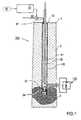
- FIG. 1 schematically shows the geological storage of carbon dioxide through an injection well.
- the injection bore extends from the surface 1 of the earth's crust 2 to the geological formation 3, in which the carbon dioxide is to be stored.
- the geological formation 3 includes, for example, porous rock.
- the injection well is illustrated with a vertical direction, but may deviate from the vertical or even horizontally.
- the fluid injection device 200 comprises in the injection bore the outer tube 50 in which the injection tube 30 extends. Between the injection and outer tubes 30, 50 of the annular pressure chamber 51 is formed, which is closed by upper and lower packer 52, 53. The injection tube 30 extends through the upper and lower packers 52, 53 into a lower end region 54 of the outer tube 50, in which the outer tube 50 is perforated. In the lower end region 54 there is furthermore a schematically represented pressure sensor device 40 (for example with an optical pressure sensor, such as the "Optical Sensor Mandrel", manufacturer Weatherford) for detecting the pressure in the geological formation 3.
- an optical pressure sensor such as the "Optical Sensor Mandrel", manufacturer Weatherford
- the outer tube 50 is cemented in the crust 2.
- the depth of the injection well to the geological formation 3 is for example 800 m. At this depth, there is an ambient pressure of around 80 bar. This ambient pressure would be significantly exceeded in the feed of liquefied carbon dioxide, the liquefaction pressure at the surface 1 of the earth's crust 2 at 25 ° C is already around 65 bar, formed by the formed in the injection tube 30 liquid column in the geological formation 3.
- the throttle valve 100 is provided.
- the dimensions of the injection bore and the throttle valve 100 are selected depending on the conditions of the specific application, in particular as a function of the fluid to be injected per unit time.
- the throttle valve 100 is arranged in the injection tube 30.
- the throttle valve 100 is located at the lower end of the injection tube 30 just above the lower packer 53, as shown schematically in the enlarged illustration. Details of the throttle valve 100 and its control with the working pressure of the pressurized fluid in the pressure chamber 51 are described below with reference to FIGS FIGS. 2 and 3 explained.
- the throttle valve 100 is controlled by the hydraulic pressure of the pressure fluid in the pressure chamber 51.
- pressurized fluid according to an important feature of the invention, preferably the water present in the annular space is used, which may be mixed with a corrosion-inhibiting additive.
- no additional lines or media are required for pressure transmission, but only the liquid column already present in the sealed annular space of the bore.
- the pressure chamber 51 is connected to the pressure source 60 via a pressure line 61, which extends through the upper packer 52, for application to the working pressure.
- the pressure source 60 comprises a pressure generator, such as a compressor or a mechanically actuated piston, for generating the working pressure in the range, for example, up to 20 bar.
- the pressure source 60 is connected to a control device 70.
- the control device 70 is also connected to the pressure sensor device 40 (see dashed arrow), in order to set the working pressure in the pressure chamber 51 as a function of the pressure in the end region 54 of the outer tube 50 via the pressure source 60.
- the function of the throttle valve 100 will be described below with reference to the opened state (FIG. FIG. 2 ) and the closed state ( FIG. 3 ).
- FIG. 2 shows the lower part of the fluid injection device with the outer tube 50 and the injection tube 30, between which the pressure chamber 51 is formed with the pressurized fluid.
- the throttle valve 100 according to the invention comprises a valve body 10 which extends in the longitudinal direction of the injection tube 30 and an inner piston chamber 11, a cover plate 12, a throttle line 13 and radially acting sealing elements 15 (O-rings).
- the valve body 10 is arranged in a valve seat 30.1, which is a part of the injection tube 30 and has inner run-on slopes 31.
- the throttle valve 100 is, apart from the throttle line 13 and details of the fluid channel 21 (see below), constructed rotationally symmetrical.
- the closed with the cover plate 12 end of the piston chamber 11 is provided on the high pressure side H of the throttle valve 100 at which, for example, a pressure of the liquid column of carbon dioxide in the injection tube 30 in the amount of about 110 bar prevails.
- the opposite end of the valve body 10 faces the low pressure side L at which a pressure of, for example, 80 bar is to be set.
- the annular piston 20 is arranged in the piston chamber 11 in the longitudinal direction radially sealing and axially displaceable.
- the fluid channel 21 is in the valve body 10 between the high pressure side H and the low pressure side L is arranged.
- the end of the fluid channel 21 on the high pressure side H is closed by a sealing plate 22 which has a projection with an annular seal 22.1 relative to the outer shape of the fluid channel 21.
- Adjacent to the sealing plate 22, a throttle opening 23 is provided in the wall of the fluid channel 21.
- a connection opening 25 for connecting the fluid channel 21 to the piston chamber 11 is provided in the wall of the fluid channel 21.
- the injection pressure on the low pressure side L can be advantageously adjusted by throttling with the throttle opening 23.
- the throttle opening 23 is provided with a specific throttle contour, which widens in the axial direction of the fluid channel 21 to the low pressure side L out.
- the throttle contour is formed for example by a cutout of the fluid channel 21. It is preferably provided a triangular contour.
- the piston chamber 11 is through the annular piston 20 in the high-pressure side annulus 11.1 (see FIG. 3 , Representation without the outer tube 50 and the pressure chamber 51) and the low-pressure side annulus 11.2 (see FIG. 2 ).
- 11.2 of the annular piston in the piston chamber 11 can be moved so that the throttle opening 23 is released (see FIG. 2 ) or closed (see FIG. 3 ).
- the working pressure in the pressure space 51 is increased so that the upward-acting control pressure in the low-pressure side annulus 11.2 exceeds the downward force of the pressure on the high-pressure side H caused by the fluid to be injected and the pressure in the reservoir is formed.
- the working pressure is transmitted hydraulically via the opening valve 32 and the throttle line 13 in the low-pressure side annulus 11.2, while in the high-pressure side annulus 11.1 by the fluid connection via the throttle opening 23 and the connecting port 25, the pressure of the high pressure side H of the throttle valve 100 prevails. Accordingly, the fluid can flow from the high pressure side via the throttle opening 23 through the fluid passage 21 to the low pressure side and also through the communication port 25 into the high pressure side annulus 11.1.
- the throttle valve 100 On the low-pressure side L, the actual pressure with the pressure sensor device 40 (see FIG FIG. 1 ).
- the throttle valve 100 is partially or completely closed.
- the working pressure in the pressure chamber 51 is reduced, so that correspondingly also the pressure in the low-pressure side annular space 11.2 decreases.
- the fluid channel 21 is first shifted so that the throttle opening 23 partially by the axial extent of the cover plate 12 (thickness the cover plate 12) is covered. Accordingly, the permeability of the throttle valve 100 is reduced.
- the liquid fluid for example carbon dioxide
- the throttle valve 100 In the opened state, the liquid fluid, for example carbon dioxide, flows from the high-pressure side H to the throttle valve 100, where it first passes the throttle opening 23 at which the desired pressure reduction takes place. With reduced pressure, the fluid flows through the fluid channel 21 on the low pressure side of the throttle valve 100 in the geological formation 3.
- the adjustment of the area of the throttle opening 23 and thus the pressure drop takes place by the axial displacement of the annular piston 20 in the valve body 10.
- the position of the throttle contour relative to the cover plate 12, which forms a throttle edge, determine the pressure drop. The pressure drop continues to depend on the volume flow.
- the control of the annular piston in the throttle valve 100 is effected by a differential pressure control.
- the balance of forces on the annular piston comprises two partial forces directed toward the low pressure side L (downward), which are formed by the pressure of the unthrottled fluid on the effective top of the throttle valve, in particular the top of the sealing plate 22, and by the throttled pressure of the fluid in the high pressure side piston chamber 11.1. and a partial force directed toward the high pressure side H (upward) formed by the working pressure of the pressurized fluid in the pressure space 51 and the low pressure side piston space 11.2, respectively.
- this force balance can be influenced so that a predetermined pressure drop is set at the throttle opening 23.
- the throttle valve 100 is opened by the pressure in the pressure chamber 51 is increased so that the upward force is greater than the resultant downward force on the annular piston 20.
- the setting of the throttle opening 23 can thus be adjusted by setting a suitable differential pressure on the annular piston. As soon as the working pressure drops, the throttle valve 100 closes automatically, since in this case only the downward partial forces act.
- the adjustment of the differential pressure may be dependent on the measured pressure in the geological formation 3 with a control loop including the control device 70 and the pressure source 60 (see FIG. 1 ) respectively.
- a control algorithm can be implemented, which uses the current pressure at the injection horizon in the geological formation 3 as a control variable. As soon as the pressure at the injection horizon exceeds a predetermined safety pressure, the working pressure in the pressure chamber 51 and thus in the low-pressure side piston chamber 11.2 is reduced, so that the annular piston 20 is pushed down and the throttle opening 23 is reduced.
- the diameter of the throttling line 13 is typically less than 5 mm, but may alternatively be made larger, in particular depending on the fluid to be injected per unit time. If, on the other hand, the pressure in the geological formation, for example, rises unexpectedly for geophysical reasons, this pressure increase has an effect up to the high-pressure-side annulus 11.1. As a result, the downward partial force on the annular piston 20 is increased, so that the throttle valve 100 closes.
- the unintentional loading of a faulty Geo is excluded.
- the throttle valve 100 is advantageously separable from the injection pipe 30 as needed, so that the complete pipe cross-section of the injection pipe 30 is available, for example, for maintenance in deeper pipe sections or for measurements in the borehole.
- the positioning and separation of the throttle valve 100 in or from the valve seat 30.1 is preferably carried out with a mounting tool 80 and a pulling tool 90.
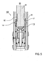
- the function of the tools 80, 90 is in the FIGS. 4 and 5 illustrated.
- the assembly tool 80 comprises a fixed tool carrier 81, at the lower end of which resilient retaining tongues 82 are provided.
- the holding tongues 82 are pivotable relative to the longitudinal extent of the tool carrier 81 and designed to engage in the mounting groove 17.
- the opening valve 32 is opened by the run-on slope 10.1 on the outside of the valve body 10 so that the low-pressure side annular space 11.2 is acted upon by the working pressure in the pressure chamber 51. Accordingly, a displacement of the annular piston 20 to the high pressure side H, so that the throttle valve 100 is opened.
- the locking levers 14 engage in a locking groove 30.2 of the valve seat 30.1, so that the throttle valve 100 is fixed ( FIG. 5 ).
- the mounting tool 80 can be released from the tool holder 16, wherein the retaining tabs 82 disengage from the mounting groove 17, and are withdrawn through the injection tube 30.
- the expansion of the throttle valve 100 is reversed by inserting a pulling tool 90 in the tool holder 16 and a withdrawal of the throttle valve 100 with the drawing tool 90.
- the pulling tool 90 includes a tool body 91 and pulling hook 92.
- the tool body 91 is immersed in the upper portion of the valve so that the inwardly projecting lower halves of the locking bars 14 are pushed outwardly so that the upper ones Folded halves and the valve is unlocked in the valve seat.
- the pulling hooks 92 snap into the mounting groove 15, so that the valve can be pulled out of the hole with the pulling tool 90.
- the interior of the injection tube 30 is separated from the outer pressure chamber 51, since the opening valve 33 is closed.
- this achieves hydraulic decoupling from the pressure chamber 51.
Landscapes
- Engineering & Computer Science (AREA)
- Geology (AREA)
- Life Sciences & Earth Sciences (AREA)
- Mining & Mineral Resources (AREA)
- Environmental & Geological Engineering (AREA)
- Fluid Mechanics (AREA)
- Physics & Mathematics (AREA)
- General Life Sciences & Earth Sciences (AREA)
- Geochemistry & Mineralogy (AREA)
- Chemical & Material Sciences (AREA)
- Chemical Kinetics & Catalysis (AREA)
- Consolidation Of Soil By Introduction Of Solidifying Substances Into Soil (AREA)
- Excavating Of Shafts Or Tunnels (AREA)
Description
- Die Erfindung betrifft ein Drosselventil gemäß dem Oberbegriff von Anspruch 1, eine Fluidinjektionseinrichtung, die mit einem derartigen Drosselventil ausgestattet ist, zur Injektion eines Fluids in eine geologische Formation, und ein Verfahren zur Injektion eines Fluids in eine geologische Formation. Die Erfindung betrifft auch Verfahren zur Montage und Demontage des Drosselventils in einem Injektionsrohrstrang.
- Es ist bekannt, in geologischen Formationen Kohlendioxid (CO2) zu speichern, das z. B. bei der Erdgasverarbeitung oder Verbrennungsprozessen anfällt. Die Speicherung von Kohlendioxid erfolgt typischerweise über ein Injektionsrohr, das in die geologische Formation reicht. Das Injektionsrohr wird aus Stabilitätsgründen in einer bis in den unteren Bereich verrohrten und zementierten Bohrung angeordnet. Zur Herstellung einer hydraulischen Kommunikation mit dem Gebirge werden die Rohre in ausgewählten Bereichen nachträglich perforiert. Vom Endbereich des Injektionsrohres soll das CO2 großräumig in die Poren des Gesteins der geologischen Formation gefüllt werden.
- Bei einer aus der Praxis bekannten technischen Realisierung ist die Injektion von CO2 im flüssigen Zustand vorgesehen. Bei einer Dichte von etwa 0,7 kg/dm3 und dem erforderlichen Verflüssigungsdruck für CO2 bei der Einspeisung (ca. 65 bar), wird am tiefsten Ende des Bohrlochs (ca. 800 m) durch den Druck des flüssigen CO2 der Umgebungsdruck in der geologischen Formation erheblich überschritten. Durch den hohen Überdruck droht eine unerwünschte Veränderung des Gesteins durch Risse, die auch die abdeckende Schicht (z. B. Ton oder Salz) oberhalb der speichernden Formation durchbrechen können. Es besteht daher ein Interesse, den Druck des flüssigen CO2 im Bohrloch durch ein Drosselventil zu reduzieren.
- Es sind zahlreiche Typen von Ventilen zur Reglung und Unterbrechung von Fluidströmen in allen Bereichen der Technik bekannt. Ventile können nach den Absperreigenschaften, den Regeleigenschaften, der Art des Antriebs, dem durchströmenden Medium oder dem Anwendungsgebiet unterschieden werden. Beispielsweise sind aus
EP 1 035 360 ,US 5 535 983 undWO 92/03676 DE 36 85 640 T2 werden ein unterirdisches Schiebehülsenventil und dessen Anbringung in einem Rohr beschrieben. AusEP 0 986 690 B1 ist ein Bohrlochventil mit einem selektiv beweglichen Ventilelement bekannt.DE 696 29 973 offenbart ein ferngesteuertes Ventil mit beweglicher Schieberspindel, das mit Hilfe von Flüssigkeit aktivierbar ist. Diese herkömmlichen Ventile haben Nachteile durch einen komplexen Aufbau und eine beschränkte Funktionssicherheit. Ein Drosselventil ist ausUS 3 381 708 auch bekannt. - In
DE 25 49 113 wird ein Hülsenventil beschrieben, bei dem der Schließzustand von der Position einer zylindrischen Hülse relativ zu einer Ventilplatte abhängig ist. Die Hülse ist mit einem Ringkolben verbunden, der in einem Zylinder gleitend gelagert ist. Durch Beaufschlagung des Zylinders mit einem Druckmittel kann der Ringkolben verschoben und damit das Hülsenventil betätigt werden. Das Hülsenventil gemäßDE 25 49 113 hat durch seinen komplexen Aufbau und die beschränkte Fähigkeit zur genau einstellbaren Druckreduzierung insbesondere unter Hochdruckbedingungen erhebliche Nachteile, durch die eine Anwendung bei geotechnischen Aufgaben und insbesondere bei der Injektion von CO2 ausgeschlossen ist. - Generell haben die herkömmlichen Ventile des Weiteren wenigstens einen der folgenden Nachteile. Erstens verfügen sie nicht gleichzeitig über eine sichere Schließfunktion und ein ausgeprägtes Regelverhalten. Zweitens muss die Energie zur Regelung über gesonderte fluidische oder elektrische Leitungen zugeführt werden. Ein weiterer Nachteil besteht in erheblichen Beschränkungen bei der Wartung und Austauschbarkeit der herkömmlichen Ventile.
- Die Aufgabe der Erfindung ist es, ein verbessertes Drosselventil, insbesondere zur Injektion eines Fluids in einen unterirdischen Speicher bereitzustellen, mit dem die Nachteile der herkömmlichen Drosselventile vermieden werden. Die Aufgabe der Erfindung ist es ferner, eine verbesserte Fluidinjektionseinrichtung bereitzustellen, mit der die Nachteile und Beschränkungen der herkömmlichen Techniken zur Fluidinjektion in unterirdische Speicher vermieden werden. Die Aufgabe der Erfindung ist es auch, ein verbessertes Verfahren zur Injektion eines Fluids in einen unterirdischen Speicher, insbesondere in eine geologische Formation bereitzustellen.
- Diese Aufgaben werden durch ein Drosselventil, eine Fluidinjektionseinrichtung und ein Injektionsverfahren mit den Merkmalen der Ansprüche 1, 16 und 22 gelöst. Vorteilhafte Ausführungsformen und Anwendungen der Erfindung ergeben sich aus den abhängigen Ansprüchen.
- Vorrichtungsbezogen basiert die Erfindung gemäß einem ersten Aspekt auf der allgemeinen technischen Lehre, ein Drosselventil mit einem Fluidkanal bereitzustellen, der Teil eines durch Druckbeaufschlagung verschiebbaren Ringkolben ist. Der Fluidkanal stellt eine verschließbare und regelbare Verbindung zwischen einer Hochdruckseite und einer Niedrigdruckseite des Drosselventils dar. Auf der Niedrigdruckseite weist der Fluidkanal ein offenes Ende auf. Auf der Hochdruckseite sind ein in Längsrichtung (axialer Richtung) des Drosselventils mit einem seitlich auskragenden Dichtteller verschlossenes Ende und eine seitliche (radiale) Drosselöffnung vorgesehen. In Abhängigkeit von der Einstellung des Ringkolbens kann der Fluidkanal so positioniert werden, dass der Dichtteller dicht schließend auf einer hochdruckseitig vorgesehenen Deckplatte aufsitzt (Schließzustand) oder die seitliche Drosselöffnung freigegeben ist (steuerbarer Durchlasszustand). Die seitliche Drosselöffnung des Fluidkanals wirkt mit der Deckplatte des Drosselventils so zusammen, dass im Durchlasszustand in Abhängigkeit von der Einstellung des Ringkolbens mit der Deckplatte ein Teil der Drosselöffnung abgedeckt oder die Drosselöffnung vollständig freigegeben wird.
- Vorteilhafterweise hat das Drosselventil einen kompakten, an die geometrischen Bedingungen im Bohrloch angepassten Aufbau mit einer hohen Druckbeständigkeit, wobei durch die Bereitstellung des Dichttellers und der seitlichen Drosselöffnung die Schließ- und Durchlassfunktionen des Drosselventils getrennt optimiert sind. Das Drosselventil erfüllt gleichzeitig eine zuverlässige Schließfunktion und eine präzise, steuerbare Öffnung im Durchlasszustand, so dass mit hoher Zuverlässigkeit und Sicherheit flüssige Fluide, insbesondere flüssiges CO2 beim zulässigen Injektionsdruck in eine geologische Formation einführbar sind.
- Gemäß einer bevorzugten Ausführungsform der Erfindung weist die Drosselöffnung eine geometrische Form (Drosselkontur) mit einer Erweiterung in Längsrichtung hin zur Niedrigdruckseite des Drosselventils, z. B. eine Dreieckform auf. Vorteilhafterweise erhält damit die Durchlassfunktion des Drosselventils eine charakteristische, nicht-lineare Kennlinie. Mit zunehmender Öffnung des Drosselventils ergibt sich für eine vorbestimmte Verschiebung des Ringkolbens ein jeweils zunehmender Öffnungszuwachs. Vorteilhafterweise kann damit die Genauigkeit der Steuerung des Drosselventils beim Öffnen und im Durchlasszustand verbessert werden.
- Der Ringkolben des öffnungsgemäßen Kolbenventils ist in einem Kolbenraum angeordnet, der beidseitig des Ringkolbens entsprechend einen hochdruckseitigen und einen niedrigdruckseitigen Ringraum aufweist. In einer bevorzugten Ausführungsform der Erfindung ist der niedrigdruckseitige Ringraum dazu vorgesehen, zur Betätigung des Drosselventils mit einem Arbeitsdruck beaufschlagt zu werden. Vorteilhafterweise wird bei Ausfall des Arbeitsdrucks der Ringkolben durch den auf der Hochdruckseite anliegenden Druck des zu injizierenden Fluids in den Schließzustand überführt. Hierzu weist der Fluidkanal erfindungsgemäß eine seitliche Verbindungsöffnung auf, durch die der Fluidkanal mit dem hochdruckseitigen Ringraum verbunden ist.
- Zur Beaufschlagung des niedrigdruckseitigen Ringraums mit dem Arbeitsdruck ist vorzugsweise eine Drosselleitung vorgesehen, über die eine Verbindung des niedrigdruckseitigen Ringraums mit der Umgebung gebildet werden kann. Vorteilhafterweise ist durch die hydraulische Druckbeaufschlagung des Drosselventils eine einzige Drosselleitung durch den Ventilkörper des Drosselventils ausreichend, so dass der kompakte und stabile Aufbau des Drosselventils nicht beeinträchtigt wird. Des Weiteren wird mit der Drosselleitung die Betriebssicherheit verbessert. Wenn beispielsweise ein unerwünschter Druckabfall auftritt, führt diese Störung zum selbsttätigen Schließen des Drosselventils. Selbst wenn der Druckabfall abrupt erfolgt, wird durch die Drosselfunktion der Drosselleitung ein Druckschlag am Drosselventil vermieden.
- Erfindungsgemäß kann der Ventilkörper des Drosselventils eine radialsymmetrische Außenform relativ zur Längsausdehnung des Kolbenraums aufweisen. Vorzugsweise sind auf der Oberfläche des Ventilkörpers Dichtungen vorgesehen, die bei eingesetztem Drosselventil mit der Innenwand eines Ventilsitzes zur Aufnahme des Drosselventils zusammenwirken. Gemäß einer weiteren bevorzugten Ausführungsform der Erfindung ist der Ventilsitz für das Drosselventil als Teil eines Injektionsrohres angeordnet, das in die geologische Formation führt. Durch die Integration des Ventilsitzes in das Injektionsrohr ergeben sich Vorteile für den kompakten Einbau des Drosselventils in das Injektionsrohr.
- Gemäß einer weiteren bevorzugten Variante der Erfindung ist ein Öffnungsventil vorgesehen, mit dem die Verbindung des niedrigdruckseitigen Ringraums mit der Umgebung geschlossen werden kann. Gemäß einer bevorzugten Variante kann das Öffnungsventil mechanisch derart betätigbar sein, dass es geöffnet ist, wenn das Drosselventil in das Injektionsrohr eingesetzt ist, und geschlossen ist, wenn das Drosselventil nicht in das Injektionsrohr eingesetzt ist. Vorteilhafterweise wird in diesem Fall das Innere des Injektionsrohres nur dann mit dem Arbeitsdruck beaufschlagt, wenn das Drosselventil in das Injektionsrohr eingesetzt ist.
- Vorzugsweise ist das Öffnungsventil Teil des Ventilsitzes, so dass durch das Öffnungsventil eine Verbindung zwischen der Umgebung des Ventilsitzes, insbesondere des Injektionsrohres, und der Drosselleitung und dem Kolbenraum des Ventilkörpers gebildet wird. Für die mechanische Betätigung des Öffnungsventils ist vorzugsweise vorgesehen, dass das Öffnungsventil beim Einsetzen des Drosselventils in den Ventilsitz geöffnet wird. Das Öffnungsventil ist federnd in einer Durchgangsöffnung des Ventilsitzes angebracht. Eine äußere Feder bewirkt ein Verschließen des Öffnungsventils bei Entnahme des Drosselventils aus dem Ventilsitz.
- Die Montierbarkeit des Drosselventils wird vorteilhafterweise vereinfacht, wenn gemäß einer weiteren bevorzugten Ausführungsform der Erfindung der Ventilkörper mindestens eine radial wirkende Eingriffseinrichtung aufweist. Als Eingriffseinrichtung ist vorzugsweise mindestens ein radial, federnd verschwenkbarer Verriegelungshebel zum Eingriff des Ventilkörpers in einen Vorsprung im Ventilsitz oder Injektionsrohr vorgesehen. Alternativ oder zusätzlich ist des Weiteren vorzugsweise eine innere Montagenut des Ventilkörpers vorgesehen, die zum Eingriff eines Montagewerkzeugs eingerichtet ist. Besonders bevorzugt sind der mindestens eine radiale Verriegelungshebel und die innere Montagenut Teil einer Werkzeugaufnahme, in die ein Montagewerkzeug des Drosselventils einsetzbar ist. Im eingesetzten Zustand des Montagewerkzeugs ist der radiale Verriegelungshebel so verschwenkt, dass der Eingriff mit dem Injektionsrohr oder dem Ventilsitz freigegeben ist, so dass durch den Eingriff eines Montagewerkzeugs in die Montagenut das Drosselventil aus dem Injektionsrohr gezogen werden kann.
- Das Montagewerkzeug zum Eingriff in die Werkzeugaufnahme weist vorzugsweise radial verschwenkbare Haltezungen auf, welche zum Eingriff in eine ringförmige Nut, insbesondere in die innere Montagenut des Drosselventils eingerichtet sind. Das Montagewerkzeug stellt einen unabhängigen Gegenstand der Erfindung dar.
- Die Lösung der obigen Aufgabe beruht gemäß einem weiteren Aspekt der Erfindung auf der Bereitstellung einer Fluidinjektionseinrichtung mit einem Injektionsrohr, an dessen Injektionsende das erfindungsgemäße Drosselventil vorgesehen ist, einem Druckraum zur Aufnahme eines Druckfluids und zur Bereitstellung eines Arbeitsdruckes, unter dessen Wirkung der Ringkolben des Drosselventils verschiebbar ist, und einer Druckquelle zur Erzeugung des Arbeitsdrucks im Druckfluid. Vorteilhafterweise wird damit eine hydraulische Steuerung des Drosselventils im Bohrloch ermöglicht. Der Injektionsdruck des in die geologische Formation einzuführenden Fluids kann unmittelbar am Injektionshorizont untertägig eingestellt werden.
- Die erfindungsgemäße Fluidinjektionseinrichtung ist vorzugsweise mit einem Außenrohr ausgestattet, welches gemeinsam mit dem Injektionsrohr den Druckraum bildet. Der Innendurchmesser des Außenrohres ist größer als der Außendurchmesser des Injektionsrohres, so dass ein ringförmiger Druckraum gebildet wird.
- Weitere Vorteile für die Sicherheit bei der Fluidinjektion in geologische Formationen ergeben sich aus der Bereitstellung einer Drucksensoreinrichtung, die in der geologischen Formation in Verbindung mit der Fluidinjektionseinrichtung oder am stromabwärts gelegenen, freien Ende des Injektionsrohres oder unmittelbar an das Drosselventil angrenzend im Injektionsrohr angeordnet ist. Gemäß einer Variante der Erfindung kann vorgesehen sein, dass die Druckquelle mit vorbestimmten Steuersignalen, wie zum Beispiel Sensorsignalen der Drucksensoreinrichtung steuerbar ist. Die Drucksensoreinrichtung ermöglicht insbesondere die Bildung eines Regelkreises, indem das Drosselventil in Abhängigkeit von den Sensorsignalen der Drucksensoreinrichtung betätigbar ist. Es ist vorzugsweise vorgesehen, den Arbeitsdruck im Druckraum in Abhängigkeit von den Sensorsignalen einzustellen. Vorteilhafterweise wird damit ein zusätzlicher Freiheitsgrad bei der Einstellung des Arbeitsdrucks im niedrigdruckseitigen Ringraum in Abhängigkeit vom Druck in der geologischen Formation bereitgestellt.
- Die Lösung der oben genannten Aufgabe beruht gemäß einem weiteren Aspekt der Erfindung auf der Bereitstellung eines Injektionsverfahrens, bei dem das erfindungsgemäße Drosselventil in das Injektionsrohr der Fluidinjektionseinrichtung eingesetzt und durch den Arbeitsdruck in der Umgebung des Drosselventils so eingestellt wird, dass die Injektion des Fluids, zum Beispiels des CO2 bei einem vorbestimmten Injektionsdruck erfolgt. Vorteilhafterweise kann das Verfahren mit großer Flexibilität realisiert werden, indem das Injektionsrohr mit dem Drosselventil in ein vorhandenes Bohrloch eingeführt und zur Fluidinjektion eingerichtet wird.
- Weitere Einzelheiten und Vorteile der Erfindung werden im folgenden unter Bezugnahme auf die beigefügten Zeichnungen beschrieben. Es zeigen:
- Figur 1:
- eine Ausführungsform einer erfindungsgemäßen Fluidinjektionseinrichtung,
- Figuren 2
- und 3: Schnittansichten einer bevorzugten Ausführungsform des erfindungsgemäßen Drosselventils im geöffneten und im geschlossenen Zustand, und
- Figuren 4
- und 5: Schnittansichten einer weiteren bevorzugten Ausführungsform des erfindungsgemäßen Drosselventils mit einem Montagewerkzeug und mit einem Ziehwerkzeug.
-
Figur 1 zeigt schematisch die geologische Speicherung von Kohlendioxid durch eine Injektionsbohrung. Die Injektionsbohrung verläuft von der Oberfläche 1 der Erdkruste 2 bis zur geologischen Formation 3, in der das Kohlendioxid gespeichert werden soll. Die geologische Formation 3 umfasst beispielsweise poröses Gestein. Die Injektionsbohrung ist mit einer vertikalen Richtung illustriert, kann aber abweichend gegenüber der Vertikalen geneigt sein oder sogar horizontal verlaufen. - Die erfindungsgemäße Fluidinjektionseinrichtung 200 umfasst in der Injektionsbohrung das Außenrohr 50, in dem das Injektionsrohr 30 verläuft. Zwischen den Injektions- und Außenrohren 30, 50 ist der ringförmige Druckraum 51 gebildet, der durch obere und untere Packer 52, 53 geschlossen ist. Das Injektionsrohr 30 verläuft durch den oberen und den unteren Packer 52, 53 bis in einen unteren Endbereich 54 des Außenrohres 50, in dem das Außenrohr 50 perforiert ist. Im unteren Endbereich 54 befindet sich des Weiteren eine schematisch dargestellte Drucksensoreinrichtung 40 (zum Beispiel mit einem optischen Drucksensor, wie dem "Optical Sensor Mandrel", Hersteller Weatherford) zur Erfassung des Drucks in der geologischen Formation 3.
- Das Außenrohr 50 ist in der Erdkruste 2 einzementiert. Die Tiefe der Injektionsbohrung bis zur geologischen Formation 3 beträgt zum Beispiel 800 m. In dieser Tiefe herrscht ein Umgebungsdruck von rund 80 bar. Dieser Umgebungsdruck würde bei der Einspeisung von verflüssigtem Kohlendioxid, dessen Verflüssigungsdruck an der Oberfläche 1 der Erdkruste 2 bei 25 °C bereits rund 65 bar beträgt, durch die im Injektionsrohr 30 gebildete Flüssigkeitssäule in der geologischen Formation 3 erheblich überschritten werden. Zur Reduzierung des Fluiddrucks am Injektionsort ist das Drosselventil 100 vorgesehen.
- Die Dimensionen der Injektionsbohrung und des Drosselventils 100 werden in Abhängigkeit von den Bedingungen der konkreten Anwendung, insbesondere in Abhängigkeit von dem pro Zeiteinheit zu injizierenden Fluid gewählt.
- Das erfindungsgemäße Drosselventil 100 ist im Injektionsrohr 30 angeordnet. Vorzugsweise befindet sich das Drosselventil 100 gemäß der schematisch vergrößerten Illustration am unteren Ende des Injektionsrohres 30 unmittelbar oberhalb des unteren Packers 53. Einzelheiten von dem Drosselventil 100 und dessen Steuerung mit dem Arbeitsdruck des Druckfluids im Druckraum 51 sind unten unter Bezug auf die
Figuren 2 und 3 erläutert. Erfindungsgemäß wird das Drosselventil 100 durch den Hydraulikdruck des Druckfluids im Druckraum 51 gesteuert. Als Druckfluid wird gemäß einem wichtigen Merkmal der Erfindung vorzugsweise das im Ringraum anstehende Wasser verwendet, das mit einem korrosionsinhibierender Zusatz versetzt sein kann. Vorteilhafterweise werden damit zur Druckübertragung keine zusätzlichen Leitungen oder Medien benötigt, sondern nur die im abgedichteten Ringraum der Bohrung ohnehin vorhandene Flüssigkeitssäule. - Der Druckraum 51 ist zur Beaufschlagung mit dem Arbeitsdruck über eine Druckleitung 61, die durch den oberen Packer 52 verläuft, mit der Druckquelle 60 verbunden. Die Druckquelle 60 umfasst einen Druckerzeuger, wie beispielsweise einen Kompressor oder einen mechanisch betätigten Kolben, zur Erzeugung des Arbeitsdrucks im Bereich zum Beispiel bis zu 20 bar. Die Druckquelle 60 ist mit einer Steuereinrichtung 70 verbunden. Vorzugsweise ist die Steuereinrichtung 70 auch mit der Drucksensoreinrichtung 40 (siehe gestrichelter Pfeil) verbunden, um über die Druckquelle 60 den Arbeitsdruck im Druckraum 51 in Abhängigkeit vom Druck im Endbereich 54 des Außenrohrs 50 einzustellen.
- Die Funktion des Drosselventils 100 wird im Folgenden unter Bezug auf den geöffneten Zustand (
Figur 2 ) und den geschlossenen Zustand (Figur 3 ) beschrieben. -
Figur 2 zeigt den unteren Teil der Fluidinjektionseinrichtung mit dem Außenrohr 50 und dem Injektionsrohr 30, zwischen denen der Druckraum 51 mit dem Druckfluid gebildet ist. Das erfindungsgemäße Drosselventil 100 umfasst einen Ventilkörper 10, der sich in Längsrichtung des Injektionsrohres 30 erstreckt und einen inneren Kolbenraum 11, eine Deckplatte 12, eine Drosselleitung 13 und radial wirkende Dichtelemente 15 (O-Ringe) aufweist. Der Ventilkörper 10 ist in einem Ventilsitz 30.1 angeordnet, der ein Teil des Injektionsrohres 30 ist und innere Anlaufschrägen 31 aufweist. Das Drosselventil 100 ist, abgesehen von der Drosselleitung 13 und Einzelheiten des Fluidkanals 21 (siehe unten), rotationssymmetrisch aufgebaut. - Das mit der Deckplatte 12 geschlossene Ende des Kolbenraums 11 ist auf der Hochdruckseite H des Drosselventils 100 vorgesehen, an der zum Beispiel ein Druck der Flüssigkeitssäule des Kohlendioxid im Injektionsrohr 30 in Höhe von rund 110 bar herrscht. Das entgegengesetzte Ende des Ventilkörpers 10 weist zur Niedrigdruckseite L, an der ein Druck von zum Beispiel 80 bar eingestellt werden soll.
- Im Kolbenraum 11 ist der rotationssymmetrische Ringkolben 20 mit dem axialen Fluidkanal 21 vorgesehen. Der Ringkolben 20 ist im Kolbenraum 11 in der Längsrichtung radial dichtend und axial verschiebbar angeordnet. Der Fluidkanal 21 ist im Ventilkörper 10 zwischen der Hochdruckseite H und der Niedrigdruckseite L angeordnet. Das Ende des Fluidkanals 21 auf der Hochdruckseite H ist durch einen Dichtteller 22 verschlossen, der relativ zur Außenform des Fluidkanals 21 eine Auskragung mit einer ringförmigen Abdichtung 22.1 aufweist. An den Dichtteller 22 angrenzend ist in der Wand des Fluidkanals 21 eine Drosselöffnung 23 vorgesehen. Des Weiteren ist in der Wand des Fluidkanals 21 eine Verbindungsöffnung 25 zur Verbindung des Fluidkanals 21 mit dem Kolbenraum 11 vorgesehen.
- Mit dem illustrierten Ventilaufbau kann vorteilhafterweise der Injektionsdruck auf der Niedrigdruckseite L durch eine Drosselung mit der Drosselöffnung 23 eingestellt werden. Für eine Druckeinstellung ist die Drosselöffnung 23 mit einer bestimmten Drosselkontur versehen, die sich in axialer Richtung des Fluidkanals 21 zur Niedrigdruckseite L hin erweitert. Die Drosselkontur wird zum Beispiel durch eine Ausfräsung des Fluidkanals 21 gebildet. Es ist vorzugsweise eine dreieckige Kontur vorgesehen.
- Der Kolbenraum 11 wird durch den Ringkolben 20 in den hochdruckseitigen Ringraum 11.1 (siehe
Figur 3 , Darstellung ohne das Außenrohr 50 und den Druckraum 51) und den niedrigdruckseitigen Ringraum 11.2 (sieheFigur 2 ) unterteilt. In Abhängigkeit vom Druckunterschied zwischen den hochdruckseitigen und niedrigdruckseitigen Ringräumen 11.1, 11.2 kann der Ringkolben im Kolbenraum 11 so verschoben werden, dass die Drosselöffnung 23 freigegeben (sieheFigur 2 ) oder geschlossen (sieheFigur 3 ) ist. Zur Einstellung des geöffneten Zustands (Durchlasszustand) wird der Arbeitsdruck im Druckraum 51 so erhöht, dass der nach oben wirkende Steuerdruck im niedrigdruckseitigen Ringraum 11.2 die nach unten gerichtete Kraftwirkung des Drucks auf der Hochdruckseite H übersteigt, der durch das zu injizierende Fluid und den Druck im Reservoir gebildet wird. Der Arbeitsdruck wird hydraulisch über das Öffnungsventil 32 und die Drosselleitung 13 in den niedrigdruckseitigen Ringraum 11.2 übertragen, während im hochdruckseitigen Ringraum 11.1 durch die Fluidverbindung über die Drosselöffnung 23 und die Verbindungsöffnung 25 der Druck der Hochdruckseite H des Drosselventils 100 herrscht. Entsprechend kann das Fluid von der Hochdruckseite über die Drosselöffnung 23 durch den Fluidkanal 21 zur Niedrigdruckseite und auch durch die Verbindungsöffnung 25 in den hochdruckseitigen Ringraum 11.1 strömen. - Auf der Niedrigdruckseite L kann der aktuelle Druck mit der Drucksensoreinrichtung 40 (siehe
Figur 1 ) erfasst werden. Wenn der Druck einen vorbestimmten Sicherheitsdruck übersteigt, wird das Drosselventil 100 teilweise oder vollständig geschlossen. Hierzu wird der Arbeitsdruck im Druckraum 51 vermindert, so dass entsprechend auch der Druck im niedrigdruckseitigen Ringraum 11.2 sinkt. Unter der Wirkung des Fluiddrucks auf der Hochdruckseite H, der auf den hochdruckseitigen Ringraum 11.1 übertragen wird, ergibt sich die Verschiebung des Ringkolbens 20. Dabei wird der Fluidkanal 21 zunächst so verschoben, dass die Drosselöffnung 23 teilweise durch die axiale Ausdehnung der Deckplatte 12 (Dicke der Deckplatte 12) abgedeckt wird. Entsprechend wird die Durchlässigkeit des Drosselventils 100 vermindert. Bei weiterer Absenkung des Drucks im niedrigdruckseitigen Ringraum 11.2 wird der Fluidkanal 21 mit dem Ringkolben 20 soweit verschoben, dass der Dichtteller 22 auf der Deckplatte 12 aufsitzt (sieheFigur 3 ). In dieser Situation ist das Drosselventil 100 im geschlossenen Zustand. Der Fluidkanal 21 ist durch die Dichtung 22.1 vollständig geschlossen. - Im geöffneten Zustand strömt das flüssige Fluid, zum Beispiel Kohlendioxid, von der Hochdruckseite H zum Drosselventil 100, wo es zunächst die Drosselöffnung 23 passiert, an der die gewünschte Druckabsenkung erfolgt. Mit vermindertem Druck strömt das Fluid durch den Fluidkanal 21 an der Niedrigdruckseite des Drosselventils 100 in die geologische Formation 3. Die Einstellung der Fläche der Drosselöffnung 23 und damit des Druckabfalls erfolgt durch die axiale Verschiebung des Ringkolbens 20 im Ventilkörper 10. Die Stellung der Drosselkontur relativ zur Deckplatte 12, die eine Drosselkante bildet, bestimmen den Druckabfall. Der Druckabfall ist weiterhin vom Volumenstrom abhängig.
- Die Steuerung des Ringkolbens im Drosselventil 100 erfolgt durch eine Differenzdrucksteuerung. Die Kräftebilanz am Ringkolben umfasst zwei zur Niedrigdruckseite L (abwärts) gerichtete Teilkräfte, die durch den Druck des ungedrosselten Fluids auf die effektive Oberseite des Drosselventils, insbesondere die Oberseite des Dichttellers 22, und durch den gedrosselten Druck des Fluids im hochdruckseitigen Kolbenraum 11.1 gebildet werden, und eine zur Hochdruckseite H (aufwärts) gerichtete Teilkraft, die durch den Arbeitsdruck des Druckfluids im Druckraum 51 beziehungsweise im niedrigdruckseitigen Kolbenraum 11.2 gebildet wird. Durch die Steuerung des Arbeitsdrucks mit der Druckquelle 60 (siehe
Figur 1 ) kann diese Kräftebilanz so beeinflusst werden, dass ein vorbestimmter Druckabfall an der Drosselöffnung 23 eingestellt wird. Das Drosselventil 100 wird geöffnet, indem der Druck im Druckraum 51 so erhöht wird, dass die aufwärtswirkende Kraft größer als die resultierende abwärtswirkende Kraft am Ringkolben 20 ist. Die Einstellung der Drosselöffnung 23 kann somit durch die Einstellung eines geeigneten Differenzdrucks am Ringkolben eingestellt werden. Sobald der Arbeitsdruck abfällt, schließt das Drosselventil 100 automatisch, da in diesem Fall ausschließlich die abwärtsgerichteten Teilkräfte wirken. - Die Einstellung des Differenzdrucks kann in Abhängigkeit von dem gemessenen Druck in der geologischen Formation 3 mit einem Regelkreis unter Einbeziehung der Steuereinrichtung 70 und der Druckquelle 60 (siehe
Figur 1 ) erfolgen. Im Regelkreis kann ein Regelalgorithmus implementiert sein, der den aktuellen Druck am Injektionshorizont in der geologischen Formation 3 als Stellgröße verwendet. Sobald der Druck am Injektionshorizont einen vorbestimmten Sicherheitsdruck überschreitet, wird der Arbeitsdruck im Druckraum 51 und damit im niedrigdruckseitigen Kolbenraum 11.2 vermindert, so dass der Ringkolben 20 abwärts geschoben und die Drosselöffnung 23 verkleinert wird. - Ein abruptes Abfließen des Druckfluids aus dem niedrigdruckseitigen Ringraum 11.2 wird durch die Dimensionierung der Drosselleitung 13 vermieden. Der Durchmesser der Drosselleitung 13 ist typischerweise geringer als 5 mm, kann aber alternativ insbesondere in Abhängigkeit von dem pro Zeiteinheit zu injizierenden Fluid größer gewählt werden. Falls andererseits der Druck in der geologischen Formation zum Beispiel aus geophysikalischen Gründen unvorhergesehen ansteigt, so wirkt sich dieser Druckanstieg bis in den hochdruckseitigen Ringraum 11.1 aus. Dadurch wird die abwärts gerichtete Teilkraft am Ringkolben 20 vergrößert, so dass sich das Drosselventil 100 schließt. Vorteilhafterweise wird damit die unbeabsichtigte Beladung eines fehlerhaften Geospeichers ausgeschlossen.
- Das Drosselventil 100 ist vorteilhafterweise bei Bedarf vom Injektionsrohr 30 trennbar, so dass der komplette Leitungsquerschnitt des Injektionsrohrs 30 zum Beispiel für Wartungsarbeiten in tiefer liegenden Rohrabschnitten oder für Messungen im Bohrloch zur Verfügung steht. Die Positionierung und Trennung des Drosselventils 100 im beziehungsweise vom Ventilsitz 30.1 erfolgt vorzugsweise mit einem Montagewerkzeug 80 und einem Ziehwerkzeug 90. Die Funktion der Werkzeuge 80, 90 ist in den
Figuren 4 und5 illustriert. - Bei der in
Figur 4 dargestellten Ausführungsform des erfindungsgemäßen Drosselventils 100 ist an dessen Hochdruckseite H eine hohlzylinderförmige Werkzeugaufnahme 16 mit radialen Verriegelungshebeln 14 und einer inneren Montagenut 17 vorgesehen. Das Montagewerkzeug 80 umfasst einen festen Werkzeugträger 81, an dessen unteren Ende federnde Haltezungen 82 vorgesehen sind. Die Haltezungen 82 sind relativ zur Längsausdehnung des Werkzeugträgers 81 verschwenkbar und zum Eingriff in die Montagenut 17 ausgelegt. - Beim Einsetzen des Drosselventils 100 (
Figur 4 ) hängt das Drosselventil 100 mit der Montagenut 17 und den Haltezungen 82 am Montagewerkzeug 80. Sobald das Drosselventil durch Absenkung des Montagewerkzeugs 80 den Ventilsitz 30.1 erreicht hat, wird durch die Anlaufschräge 10.1 auf der Außenseite des Ventilkörpers 10 das Öffnungsventil 32 geöffnet, so dass der niedrigdruckseitige Ringraum 11.2 mit dem Arbeitsdruck im Druckraum 51 beaufschlagt wird. Entsprechend erfolgt eine Verschiebung des Ringkolbens 20 zur Hochdruckseite H, so dass das Drosselventil 100 geöffnet ist. Gleichzeitig greifen die Verriegelungshebel 14 in eine Sperrnut 30.2 des Ventilsitzes 30.1, so dass das Drosselventil 100 fixiert wird (Figur 5 ). In dieser Situation kann das Montagewerkzeug 80 von der Werkzeugaufnahme 16 gelöst werden, wobei die Haltezungen 82 aus der Montagenut 17 ausrasten, und durch das Injektionsrohr 30 zurückgezogen werden. - Der Ausbau des Drosselventils 100 erfolgt umgekehrt durch ein Einsetzen eines Ziehwerkzeugs 90 in die Werkzeugaufnahme 16 und einen Rückzug des Drosselventils 100 mit dem Ziehwerkzeug 90. Das Ziehwerkzeug 90 umfasst einen Werkzeugkörper 91 und Ziehhaken 92. Beim Einsetzen des Ziehwerkzeugs 90 wird der Werkzeugkörper 91 in den oberen Bereich des Ventils eingetaucht, so dass die nach innen ragenden, unteren Hälftender Sperrriegel 14 nach außen gedrückt werden, so dass die oberen Hälften eingeklappt werden und das Ventil im Ventilsitz entriegelt wird. Die Ziehhaken 92 rasten in die Montagenut 15, so dass das Ventil mit dem Ziehwerkzeug 90 aus der Bohrung gezogen werden kann. Im ausgebauten Zustand ist das Innere des Injektionsrohres 30 vom äußeren Druckraum 51 getrennt, da das Öffnungsventil 33 geschlossen ist. Vorteilhafterweise wird dadurch eine hydraulische Entkoppelung vom Druckraum 51 erreicht.
- Die in der vorstehenden Beschreibung, den Zeichnungen und den Ansprüchen offenbarten Merkmale der Erfindung können sowohl einzeln als auch in Kombination für die Verwirklichung der Erfindung in Ihren verschiedenen Ausgestaltungen von Bedeutung sein.
Claims (31)
- Drosselventil (100), insbesondere zur Injektion eines Fluids in eine geologische Formation, das umfasst:- einen Ventilkörper (10) mit einem Kolbenraum (11),- einen Ringkolben (20) mit einem axialen Fluidkanal (21), der sich von einer Hochdruckseite (H) zu einer Niedrigdruckseite (L) des Drosselventils erstreckt, wobei der Ringkolben (20) im Kolbenraum (11) verschiebbar ist und der Fluidkanal (21) in Abhängigkeit von der Position des Ringkolbens (20) im Kolbenraum (11) durchlässig oder geschlossen ist,- eine Deckplatte (12), die an der Hochdruckseite (H) des Ventilkörpers (10) vorgesehen ist und durch die der Fluidkanal (21) vom Kolbenraum (11) zur Hochdruckseite (H) ragt,
dadurch gekennzeichnet, dass- der Fluidkanal (21) in axialer Richtung mit einem Dichtteller (22) verschlossen ist, der auf der Hochdruckseite (H) auf die Deckplatte (12) dichtend aufsetzbar ist, und- der Fluidkanal (21) an den Dichtteller (22) angrenzend eine radiale Drosselöffnung (23) aufweist. - Drosselventil nach Anspruch 1, bei dem die Drosselöffnung (23) eine Drosselkontur aufweist, die sich in axialer Richtung zur Niedrigdruckseite (L) erweitert.
- Drosselventil nach Anspruch 1 oder 2, bei dem der Ringkolben (20) einen Kolbenkörper (24) aufweist, durch den der Kolbenraum (11) in einen hochdruckseitigen und einen niedrigdruckseitigen Ringraum (11.1, 11.2) geteilt wird, und der niedrigdruckseitige Ringraum (11.2) eingerichtet ist, mit einem Arbeitsdruck in einer Umgebung des Ventilkörpers (10) beaufschlagt zu werden.
- Drosselventil nach Anspruch 3, bei dem der Fluidkanal (21) durch eine radiale Verbindungsöffnung (25) mit dem hochdruckseitigen Ringraum (11.1) verbunden ist.
- Drosselventil nach Anspruch 3 oder 4, bei dem der niedrigdruckseitige Ringraum (11.2) über eine Drosselleitung (13) mit der Umgebung des Ventilkörpers (10) verbunden ist.
- Drosselventil nach mindestens einem der vorhergehenden Ansprüche, bei dem die Oberfläche des Ventilkörpers (10) eine radialsymmetrische Außenkontur aufweist.
- Drosselventil nach mindestens einem der vorhergehenden Ansprüche, bei dem auf einer Oberfläche des Ventilkörpers (10) radial wirkende Dichtelemente (15) vorgesehen sind.
- Drosselventil nach mindestens einem der vorhergehenden Ansprüche, das einen Ventilsitz (31) aufweist, der Teil eines Injektionsrohres (30) ist.
- Drosselventil nach Anspruch 8, bei dem im Ventilsitz (31) ein Öffnungsventil (32) zur Bildung einer Verbindung zwischen einer Umgebung des Injektionsrohres und dem Drosselventil vorgesehen ist.
- Drosselventil nach Anspruch 9, bei dem die Drosselleitung (13) mit dem Öffnungsventil (32) verbunden ist.
- Drosselventil nach Anspruch 9 oder 10, bei dem das Öffnungsventil (32) durch ein Einsetzen des Ventilkörpers (10) in den Ventilsitz (31) betätigbar ist.
- Drosselventil nach mindestens einem der vorhergehenden Ansprüche, bei dem der Ventilkörper (10) eine Eingriffseinrichtung aufweist, die mindestens einen radialen Verriegelungshebel (14) und/oder eine innere Montagenut (17) umfasst.
- Drosselventil nach Anspruch 12, bei dem der Ventilkörper (10) eine Werkzeugaufnahme (16) aufweist, in der die innere Montagenut (17) und der mindestens eine radiale Verriegelungshebel (14) vorgesehen sind, wobei in die Werkzeugaufnahme (16) ein Montagewerkzeug (80) einsetzbar ist, mit dem im eingesetzten Zustand der mindestens eine radiale Verriegelungshebel (14) betätigbar ist.
- Drosselventil nach Anspruch 13, das mit dem Montagewerkzeug (80) verbunden ist.
- Drosselventil nach Anspruch 14, bei dem das Montagewerkzeug (80) Haltezungen (82) aufweist, die in die innere Montagenut (17) eingreifen.
- Fluidinjektionseinrichtung (200), insbesondere zur Injektion eines Fluids in eine geologische Formation, die umfasst:- ein Injektionsrohr (30), in dem ein Drosselventil (100) nach mindestens einem der vorhergehenden Ansprüche angeordnet ist,- einen Druckraum (51) zur Bildung eines Arbeitsdruckes in der Umgebung des Drosselventils (100), und- eine Druckquelle (60) zur Beaufschlagung des Druckraumes (51) mit dem Arbeitsdruck.
- Fluidinjektionseinrichtung nach Anspruch 16, die ein Außenrohr (50) aufweist, in dem das Injektionsrohr (30) angeordnet ist, wobei der Druckraum (51) zwischen dem Außenrohr (50) und dem Injektionsrohr (30) gebildet ist.
- Fluidinjektionseinrichtung nach Anspruch 16 oder 17, die mit einer Drucksensoreinrichtung (40) ausgestattet ist.
- Fluidinjektionseinrichtung nach Anspruch 18, die einen Regelkreis aufweist, mit dem das Drosselventil (100) in Abhängigkeit von Sensorsignalen der Drucksensoreinrichtung (40) betätigbar ist.
- Fluidinjektionseinrichtung nach mindestens einem der Ansprüche 16 bis 19, bei der das Injektionsrohr (30) einen Ventilsitz (31) mit Anlaufschrägen (32) zur Aufnahme des Drosselventils (100) aufweist.
- Fluidinjektionseinrichtung nach mindestens einem der Ansprüche 16 bis 20, bei der als Druckfluid das im Druckraum (51) anstehende Wasser verwendet wird.
- Verfahren zur Injektion eines Fluids in eine geologische Formation, mit den Schritten:- Einsetzen eines Drosselventils (100) nach mindestens einem der Ansprüche 1 bis 15 in ein Injektionsrohr (30), das in die geologische Formation ragt,- Einstellung des Drosselventils (100) durch einen Arbeitsdruck in der Umgebung des Injektionsrohres (30), und- Injektion des Fluids in die geologische Formation durch das Injektionsrohr (30) und das Drosselventil (100).
- Verfahren nach Anspruch 22, bei dem der Arbeitsdruck in einem Ringraum (51) zwischen dem Injektionsrohr (30) und einem Außenrohr (50) erzeugt wird.
- Verfahren nach Anspruch 23, bei dem der Arbeitsdruck über das Öffnungsventil (31) und die Drosselleitung (13) auf das Drosselventil (100) ausgeübt wird.
- Verfahren nach Anspruch 24, bei dem das Öffnungsventil (31) mit dem Einsetzen des Drosselventils (100) in das Injektionsrohr (30) geöffnet wird.
- Verfahren nach mindestens einem der Ansprüche 22 bis 25, bei dem der Arbeitsdruck in Abhängigkeit von einem Betriebsdruck stromabwärts vom Drosselventil (100) eingestellt wird.
- Verfahren nach mindestens einem der Ansprüche 22 bis 26, bei dem das Einsetzen des Drosselventils (100) eine lösbare Befestigung in einem Ventilsitz (31) des Injektionsrohres (30) umfasst.
- Verfahren nach Anspruch 27, bei dem das Einsetzen des Drosselventils (100) ein Einschieben eines Montagewerkzeugs (80) in das Injektionsrohr (30) umfasst, bis radiale Verriegelungshebel (14) des Ventilkörpers (10) des Drosselventils (100) in eine Sperrnut (30.2) im Inneren des Injektionsrohres (30) eingreifen.
- Verfahren nach Anspruch 28, bei dem das Abziehen des Drosselventils (100) ein Einschieben eines Ziehwerkzeugs (90) in das Injektionsrohr (30) umfasst, bis ein Werkzeugkörper (91) des Ziehwerkzeugs (90) die radialen Verriegelungshebel (14) von der Sperrnut (30.2) löst.
- Verfahren nach mindestens einem der Ansprüche 22 bis 29, bei dem das injizierte Fluid flüssiges Kohlendioxid umfasst.
- Verwendung eines Drosselventils (100) nach mindestens einem der Ansprüche 1 bis 15 oder einer Fluidinjektionseinrichtung (200) nach mindestens einem der Ansprüche 16 bis 21 zur Injektion von flüssigem Kohlendioxid in eine geologische Formation.
Applications Claiming Priority (1)
| Application Number | Priority Date | Filing Date | Title |
|---|---|---|---|
| DE102006027705A DE102006027705B3 (de) | 2006-06-14 | 2006-06-14 | Drosselventil zur Fluidinjektion in geologische Formationen |
Publications (2)
| Publication Number | Publication Date |
|---|---|
| EP1867832A1 EP1867832A1 (de) | 2007-12-19 |
| EP1867832B1 true EP1867832B1 (de) | 2009-08-05 |
Family
ID=38441953
Family Applications (1)
| Application Number | Title | Priority Date | Filing Date |
|---|---|---|---|
| EP07010996A Not-in-force EP1867832B1 (de) | 2006-06-14 | 2007-06-04 | Drosselventil zur Fluidinjektion in geologische Formationen |
Country Status (7)
| Country | Link |
|---|---|
| US (1) | US7640992B2 (de) |
| EP (1) | EP1867832B1 (de) |
| AT (1) | ATE438784T1 (de) |
| CA (1) | CA2591317A1 (de) |
| DE (1) | DE102006027705B3 (de) |
| DK (1) | DK1867832T3 (de) |
| NO (1) | NO20072905L (de) |
Families Citing this family (10)
| Publication number | Priority date | Publication date | Assignee | Title |
|---|---|---|---|---|
| EP2233690A1 (de) * | 2009-03-13 | 2010-09-29 | BP Alternative Energy International Limited | Flüssigkeitseinspritzung |
| DK2505773T3 (da) * | 2011-03-30 | 2013-06-10 | Welltec As | Trykudligningsanordning |
| CN103899284A (zh) * | 2014-03-05 | 2014-07-02 | 陕西延长石油(集团)有限责任公司研究院 | 移动式液态co2注入撬装装置 |
| CN105089581B (zh) * | 2014-05-14 | 2018-08-14 | 中国石油天然气股份有限公司 | 一种大管径气井井下流量控制装置及工艺方法 |
| US9683424B2 (en) | 2015-02-06 | 2017-06-20 | Comitt Well Solutions Us Holding Inc. | Apparatus for injecting a fluid into a geological formation |
| CN111042765B (zh) * | 2020-01-16 | 2021-11-16 | 中国海洋石油集团有限公司 | 一种井下流量控制阀 |
| CN111167145B (zh) * | 2020-03-11 | 2023-06-23 | 上海一核阀门股份有限公司 | 一种用于参杂固体颗粒流体的闪蒸管段及其控制方法 |
| WO2023244855A1 (en) * | 2022-06-17 | 2023-12-21 | Air Products And Chemicals, Inc. | Methods and systems to manage impure co2 injection |
| CN116136160B (zh) * | 2023-04-19 | 2023-06-27 | 贵州航天凯山石油仪器有限公司 | 一种用于井下二氧化碳流量控制的阀门及方法 |
| CN120384725B (zh) * | 2025-05-16 | 2025-10-31 | 廊坊市派博力克科贸有限公司 | 一种免打捞式节流器 |
Family Cites Families (14)
| Publication number | Priority date | Publication date | Assignee | Title |
|---|---|---|---|---|
| US3381708A (en) * | 1965-09-07 | 1968-05-07 | Baker Oil Tools Inc | Fluid flow regulator |
| US3521853A (en) * | 1966-12-12 | 1970-07-28 | Thomas S Gillis Jr | Throttle and shutoff valve |
| US3834414A (en) * | 1972-08-29 | 1974-09-10 | Mc Murry Oil Tools Inc | Method and apparatus for gas-lift production of liquid from wells |
| CH590419A5 (de) * | 1975-10-10 | 1977-08-15 | Bbc Brown Boveri & Cie | |
| US4651829A (en) * | 1985-12-13 | 1987-03-24 | Halliburton Company | Subsurface control valve |
| US4825895A (en) * | 1987-06-16 | 1989-05-02 | Chevron Research Company | Water injection choke valve |
| DE9012109U1 (de) * | 1990-08-23 | 1990-10-31 | Stanelle, Karl-Heinz, 7129 Güglingen | Quetschventil |
| US5320181A (en) * | 1992-09-28 | 1994-06-14 | Wellheads & Safety Control, Inc. | Combination check valve & back pressure valve |
| US5836395A (en) * | 1994-08-01 | 1998-11-17 | Weatherford/Lamb, Inc. | Valve for wellbore use |
| ATE173068T1 (de) * | 1994-07-01 | 1998-11-15 | Ho Matic Ag | Schlauchquetschventil |
| US5535767A (en) * | 1995-03-14 | 1996-07-16 | Halliburton Company | Remotely actuated adjustable choke valve and method for using same |
| US5979558A (en) * | 1997-07-21 | 1999-11-09 | Bouldin; Brett Wayne | Variable choke for use in a subterranean well |
| US6102361A (en) * | 1999-03-05 | 2000-08-15 | Riikonen; Esko A. | Fluidic pinch valve system |
| WO2000079098A1 (en) * | 1999-06-18 | 2000-12-28 | Halliburton Energy Services, Inc. | System and method for enhancing the recovery of fluids from a formation |
-
2006
- 2006-06-14 DE DE102006027705A patent/DE102006027705B3/de not_active Expired - Fee Related
-
2007
- 2007-06-04 EP EP07010996A patent/EP1867832B1/de not_active Not-in-force
- 2007-06-04 DK DK07010996T patent/DK1867832T3/da active
- 2007-06-04 AT AT07010996T patent/ATE438784T1/de active
- 2007-06-07 US US11/810,815 patent/US7640992B2/en not_active Expired - Fee Related
- 2007-06-07 NO NO20072905A patent/NO20072905L/no not_active Application Discontinuation
- 2007-06-12 CA CA002591317A patent/CA2591317A1/en not_active Abandoned
Also Published As
| Publication number | Publication date |
|---|---|
| US20070295512A1 (en) | 2007-12-27 |
| DE102006027705B3 (de) | 2008-02-21 |
| NO20072905L (no) | 2007-12-17 |
| CA2591317A1 (en) | 2007-12-14 |
| EP1867832A1 (de) | 2007-12-19 |
| US7640992B2 (en) | 2010-01-05 |
| DK1867832T3 (da) | 2009-12-07 |
| ATE438784T1 (de) | 2009-08-15 |
Similar Documents
| Publication | Publication Date | Title |
|---|---|---|
| EP1867832A1 (de) | Drosselventil zur Fluidinjektion in geologische Formationen | |
| DE68928332T2 (de) | Verfahren und Vorrichtung zum hydraulischen und wahlweisen steuern von mindestens zwei Werkzeugen oder Instrumenten eines Gerätes, Ventil zur Durchführung dieses Verfahrens oder Benutzung dieses Geräts | |
| DE2735602C2 (de) | Vorrichtung und Verfahren zum Steuern des Mengenstroms durch eine Förderleitung und zur Injektion eines chemischen Mediums in die Förderleitung | |
| DE69312336T2 (de) | Prüfstrang zur Untersuchung mit einem am Ende eines Rohrstranges angebrachten Perforator | |
| DE2430549C2 (de) | Sicherheitsventilanordnung zum Einsatz in Bohrlöchern | |
| DE60208578T2 (de) | Vorrichtung zum verrohren eines teiles des bohrloches | |
| EP0397870B1 (de) | Verfahren zur befestigung der produktiven schicht innerhalb einer bohrung | |
| DE202022101554U1 (de) | Durchflussregulierungs-, Wasserkontroll- und Versauerungskomplettiergerät für Öl- und Gasbrunnen | |
| DE60200550T2 (de) | Vorrichtung zur verankerung eines bohrgestänges in einem bohrloch | |
| DE3025435C2 (de) | Druckkernrohr-Baugruppe und Verfahren zu deren Verwendung | |
| DE2364328A1 (de) | Sicherheitsventilanordnung fuer ein foerderbohrloch | |
| DE69626342T2 (de) | Bohrlochwerkzeug mit Differenzdrucktest oder -bypassventil | |
| DE69225596T2 (de) | Rohruntersuchungsventil | |
| DE69818477T2 (de) | Veränderbares drosselventil zur verwendung in einer unterirdischen bohrung und verfahren zur steuerung einer flüssigkeitsströmung | |
| DE69728052T2 (de) | Verfahren zur beschleunigung der produktion | |
| DE2714049A1 (de) | Bohrlochsicherungsvorrichtung | |
| DE112022000456T5 (de) | Bohrloch-Dampfübergangssteuerventil zur Fluideinspritzung | |
| DE69629692T2 (de) | Verfahren zur unterstützung der produktion | |
| DE112016005583T5 (de) | Unterirdisches Sicherheitsventil mit dauerhaftem, in der offenen Position verriegelten Element | |
| DE2812714A1 (de) | Bohrlochventilvorrichtung | |
| DE2255949C2 (de) | Bohrlochprüfgerät | |
| DE8318405U1 (de) | Fernsteuerbare drosseleinrichtung | |
| DE2702662C3 (de) | Steuervorrichtung zum Totpumpen einer Förderbohrung | |
| DE3107886A1 (de) | Rueckschlagventilanordnung zur verwendung in einem bohrloch | |
| DE2226860A1 (de) | Stroemungsgeschwindigkeitsabhaengiger sicherheitsventilmechanismus |
Legal Events
| Date | Code | Title | Description |
|---|---|---|---|
| PUAI | Public reference made under article 153(3) epc to a published international application that has entered the european phase |
Free format text: ORIGINAL CODE: 0009012 |
|
| AK | Designated contracting states |
Kind code of ref document: A1 Designated state(s): AT BE BG CH CY CZ DE DK EE ES FI FR GB GR HU IE IS IT LI LT LU LV MC MT NL PL PT RO SE SI SK TR |
|
| AX | Request for extension of the european patent |
Extension state: AL BA HR MK YU |
|
| 17P | Request for examination filed |
Effective date: 20080416 |
|
| AKX | Designation fees paid |
Designated state(s): AT DK FR GB NL SE |
|
| REG | Reference to a national code |
Ref country code: DE Ref legal event code: 8566 |
|
| GRAP | Despatch of communication of intention to grant a patent |
Free format text: ORIGINAL CODE: EPIDOSNIGR1 |
|
| RAP1 | Party data changed (applicant data changed or rights of an application transferred) |
Owner name: HELMHOLTZ-ZENTRUM POTSDAM DEUTSCHES GEOFORSCHUNGSZ |
|
| GRAS | Grant fee paid |
Free format text: ORIGINAL CODE: EPIDOSNIGR3 |
|
| GRAA | (expected) grant |
Free format text: ORIGINAL CODE: 0009210 |
|
| AK | Designated contracting states |
Kind code of ref document: B1 Designated state(s): AT DK FR GB NL SE |
|
| REG | Reference to a national code |
Ref country code: GB Ref legal event code: FG4D Free format text: NOT ENGLISH |
|
| REG | Reference to a national code |
Ref country code: SE Ref legal event code: TRGR |
|
| REG | Reference to a national code |
Ref country code: DK Ref legal event code: T3 |
|
| PLBE | No opposition filed within time limit |
Free format text: ORIGINAL CODE: 0009261 |
|
| STAA | Information on the status of an ep patent application or granted ep patent |
Free format text: STATUS: NO OPPOSITION FILED WITHIN TIME LIMIT |
|
| 26N | No opposition filed |
Effective date: 20100507 |
|
| PGFP | Annual fee paid to national office [announced via postgrant information from national office to epo] |
Ref country code: SE Payment date: 20110622 Year of fee payment: 5 |
|
| PGFP | Annual fee paid to national office [announced via postgrant information from national office to epo] |
Ref country code: DK Payment date: 20110518 Year of fee payment: 5 Ref country code: GB Payment date: 20110601 Year of fee payment: 5 Ref country code: NL Payment date: 20110524 Year of fee payment: 5 |
|
| PGFP | Annual fee paid to national office [announced via postgrant information from national office to epo] |
Ref country code: FR Payment date: 20110715 Year of fee payment: 5 |
|
| REG | Reference to a national code |
Ref country code: NL Ref legal event code: V1 Effective date: 20130101 |
|
| REG | Reference to a national code |
Ref country code: DK Ref legal event code: EBP |
|
| REG | Reference to a national code |
Ref country code: SE Ref legal event code: EUG |
|
| GBPC | Gb: european patent ceased through non-payment of renewal fee |
Effective date: 20120604 |
|
| PG25 | Lapsed in a contracting state [announced via postgrant information from national office to epo] |
Ref country code: SE Free format text: LAPSE BECAUSE OF NON-PAYMENT OF DUE FEES Effective date: 20120605 |
|
| REG | Reference to a national code |
Ref country code: FR Ref legal event code: ST Effective date: 20130228 |
|
| PG25 | Lapsed in a contracting state [announced via postgrant information from national office to epo] |
Ref country code: NL Free format text: LAPSE BECAUSE OF NON-PAYMENT OF DUE FEES Effective date: 20130101 Ref country code: FR Free format text: LAPSE BECAUSE OF NON-PAYMENT OF DUE FEES Effective date: 20120702 Ref country code: GB Free format text: LAPSE BECAUSE OF NON-PAYMENT OF DUE FEES Effective date: 20120604 |
|
| PG25 | Lapsed in a contracting state [announced via postgrant information from national office to epo] |
Ref country code: DK Free format text: LAPSE BECAUSE OF NON-PAYMENT OF DUE FEES Effective date: 20120702 |
|
| REG | Reference to a national code |
Ref country code: AT Ref legal event code: MM01 Ref document number: 438784 Country of ref document: AT Kind code of ref document: T Effective date: 20120604 |
|
| PG25 | Lapsed in a contracting state [announced via postgrant information from national office to epo] |
Ref country code: AT Free format text: LAPSE BECAUSE OF NON-PAYMENT OF DUE FEES Effective date: 20120604 |