EP1867825A2 - Antrieb für den Flügel einer Tür oder eines Fensters - Google Patents
Antrieb für den Flügel einer Tür oder eines Fensters Download PDFInfo
- Publication number
- EP1867825A2 EP1867825A2 EP07110031A EP07110031A EP1867825A2 EP 1867825 A2 EP1867825 A2 EP 1867825A2 EP 07110031 A EP07110031 A EP 07110031A EP 07110031 A EP07110031 A EP 07110031A EP 1867825 A2 EP1867825 A2 EP 1867825A2
- Authority
- EP
- European Patent Office
- Prior art keywords
- piston
- spring
- closing
- drive
- hydraulic pump
- Prior art date
- Legal status (The legal status is an assumption and is not a legal conclusion. Google has not performed a legal analysis and makes no representation as to the accuracy of the status listed.)
- Granted
Links
Images
Classifications
-
- E—FIXED CONSTRUCTIONS
- E05—LOCKS; KEYS; WINDOW OR DOOR FITTINGS; SAFES
- E05F—DEVICES FOR MOVING WINGS INTO OPEN OR CLOSED POSITION; CHECKS FOR WINGS; WING FITTINGS NOT OTHERWISE PROVIDED FOR, CONCERNED WITH THE FUNCTIONING OF THE WING
- E05F3/00—Closers or openers with braking devices, e.g. checks; Construction of pneumatic or liquid braking devices
- E05F3/04—Closers or openers with braking devices, e.g. checks; Construction of pneumatic or liquid braking devices with liquid piston brakes
- E05F3/10—Closers or openers with braking devices, e.g. checks; Construction of pneumatic or liquid braking devices with liquid piston brakes with a spring, other than a torsion spring, and a piston, the axes of which are the same or lie in the same direction
- E05F3/102—Closers or openers with braking devices, e.g. checks; Construction of pneumatic or liquid braking devices with liquid piston brakes with a spring, other than a torsion spring, and a piston, the axes of which are the same or lie in the same direction with rack-and-pinion transmission between driving shaft and piston within the closer housing
-
- E—FIXED CONSTRUCTIONS
- E05—LOCKS; KEYS; WINDOW OR DOOR FITTINGS; SAFES
- E05F—DEVICES FOR MOVING WINGS INTO OPEN OR CLOSED POSITION; CHECKS FOR WINGS; WING FITTINGS NOT OTHERWISE PROVIDED FOR, CONCERNED WITH THE FUNCTIONING OF THE WING
- E05F15/00—Power-operated mechanisms for wings
- E05F15/60—Power-operated mechanisms for wings using electrical actuators
- E05F15/603—Power-operated mechanisms for wings using electrical actuators using rotary electromotors
- E05F15/611—Power-operated mechanisms for wings using electrical actuators using rotary electromotors for swinging wings
- E05F15/63—Power-operated mechanisms for wings using electrical actuators using rotary electromotors for swinging wings operated by swinging arms
-
- E—FIXED CONSTRUCTIONS
- E05—LOCKS; KEYS; WINDOW OR DOOR FITTINGS; SAFES
- E05F—DEVICES FOR MOVING WINGS INTO OPEN OR CLOSED POSITION; CHECKS FOR WINGS; WING FITTINGS NOT OTHERWISE PROVIDED FOR, CONCERNED WITH THE FUNCTIONING OF THE WING
- E05F3/00—Closers or openers with braking devices, e.g. checks; Construction of pneumatic or liquid braking devices
- E05F3/04—Closers or openers with braking devices, e.g. checks; Construction of pneumatic or liquid braking devices with liquid piston brakes
- E05F3/12—Special devices controlling the circulation of the liquid, e.g. valve arrangement
-
- E—FIXED CONSTRUCTIONS
- E05—LOCKS; KEYS; WINDOW OR DOOR FITTINGS; SAFES
- E05F—DEVICES FOR MOVING WINGS INTO OPEN OR CLOSED POSITION; CHECKS FOR WINGS; WING FITTINGS NOT OTHERWISE PROVIDED FOR, CONCERNED WITH THE FUNCTIONING OF THE WING
- E05F3/00—Closers or openers with braking devices, e.g. checks; Construction of pneumatic or liquid braking devices
- E05F3/22—Additional arrangements for closers, e.g. for holding the wing in opened or other position
- E05F3/224—Additional arrangements for closers, e.g. for holding the wing in opened or other position for assisting in opening the wing
-
- E—FIXED CONSTRUCTIONS
- E05—LOCKS; KEYS; WINDOW OR DOOR FITTINGS; SAFES
- E05Y—INDEXING SCHEME ASSOCIATED WITH SUBCLASSES E05D AND E05F, RELATING TO CONSTRUCTION ELEMENTS, ELECTRIC CONTROL, POWER SUPPLY, POWER SIGNAL OR TRANSMISSION, USER INTERFACES, MOUNTING OR COUPLING, DETAILS, ACCESSORIES, AUXILIARY OPERATIONS NOT OTHERWISE PROVIDED FOR, APPLICATION THEREOF
- E05Y2400/00—Electronic control; Electrical power; Power supply; Power or signal transmission; User interfaces
- E05Y2400/10—Electronic control
- E05Y2400/30—Electronic control of motors
- E05Y2400/3013—Electronic control of motors during manual wing operation
- E05Y2400/3015—Power assistance
-
- E—FIXED CONSTRUCTIONS
- E05—LOCKS; KEYS; WINDOW OR DOOR FITTINGS; SAFES
- E05Y—INDEXING SCHEME ASSOCIATED WITH SUBCLASSES E05D AND E05F, RELATING TO CONSTRUCTION ELEMENTS, ELECTRIC CONTROL, POWER SUPPLY, POWER SIGNAL OR TRANSMISSION, USER INTERFACES, MOUNTING OR COUPLING, DETAILS, ACCESSORIES, AUXILIARY OPERATIONS NOT OTHERWISE PROVIDED FOR, APPLICATION THEREOF
- E05Y2400/00—Electronic control; Electrical power; Power supply; Power or signal transmission; User interfaces
- E05Y2400/10—Electronic control
- E05Y2400/32—Position control, detection or monitoring
- E05Y2400/322—Position control, detection or monitoring by using absolute position sensors
- E05Y2400/328—Position control, detection or monitoring by using absolute position sensors of the linear type
-
- E—FIXED CONSTRUCTIONS
- E05—LOCKS; KEYS; WINDOW OR DOOR FITTINGS; SAFES
- E05Y—INDEXING SCHEME ASSOCIATED WITH SUBCLASSES E05D AND E05F, RELATING TO CONSTRUCTION ELEMENTS, ELECTRIC CONTROL, POWER SUPPLY, POWER SIGNAL OR TRANSMISSION, USER INTERFACES, MOUNTING OR COUPLING, DETAILS, ACCESSORIES, AUXILIARY OPERATIONS NOT OTHERWISE PROVIDED FOR, APPLICATION THEREOF
- E05Y2900/00—Application of doors, windows, wings or fittings thereof
- E05Y2900/10—Application of doors, windows, wings or fittings thereof for buildings or parts thereof
- E05Y2900/13—Type of wing
- E05Y2900/132—Doors
Definitions
- the invention relates to a drive for a wing of a door or a window with the features of claim 1.
- a door drive is known, with a hydraulic closing device, with hydraulic piston-cylinder unit and closing spring, with a motor opening device with a hydraulic pump and an electric motor, wherein the motor opening operation, the pressure of the hydraulic medium is adjusted to the instantaneous force of the closing spring.
- the piston is slidably guided in the hydraulic cylinder to form a pressure chamber and a Drucklosraums, wherein cooperating with the piston closing spring - or a spring tuned to this - is supported with its one end on the piston and with its other end on a hydraulic pressure pad.
- the same hydraulic pressure is regulated.
- a valve member is arranged, which can be actuated via different hydraulic channels.
- the door drive has a complex construction, as the hydraulic pressure is adjusted to the momentary force of the closing spring.
- the valve member for controlling a plurality of sealing edges, which cooperate with hydraulic channels.
- the invention has for its object to form a simple, inexpensive drive for the wing of a door or a window and a method for easy control of the drive to do so.
- the drive according to the invention for a wing of a door or a window has a designed as a compression spring energy storage, which is charged by manual opening and causes the wing is guided after opening again in its closed position.
- door drives are used for this purpose, which effect the introduction of force onto the door via a linkage connected in a hinged manner or via a lever guided in a slide rail by a sliding block.
- the door drive can be fixed to the frame or on the door leaf.
- the lever or the linkage as a power transmission element based, depending on the selected arrangement, either on the door leaf or on the frame.
- the drive has a housing, with a receiving space in which the compression spring and a displaceable closing piston are arranged.
- the closing piston cooperates with an output shaft, which is connected to the lever or the linkage for actuating the wing.
- the receiving space is filled with a hydraulic fluid.
- the closing piston divides the receiving space of the housing in a piston chamber and a spring chamber.
- the compression spring is arranged, which is supported on the one hand on the closing piston and on the other hand on a further arranged in the receiving space spring piston.
- the spring piston is designed as a stepped piston, with a smaller diameter approach, which is guided in a correspondingly tapered region of the receiving space.
- the spring piston separates a storage space in the receiving space and forms with its approach a pressure chamber in the tapered region of the receiving space.
- the spring piston is assigned no valve function, whereby a simple construction is possible.
- the various areas in the receiving space are interconnected by overflow, wherein the overflow can be formed in the housing, for example, during the manufacture of the housing through Extrusion, or they are subsequently produced by machining by drilling or by spark erosion.
- valves can be arranged, which serve to influence the behavior of the drive. With the valves, the closing speed of the drive or an opening damping can be adjusted.
- one of the overflow channels is assigned a hydraulic pump which makes it possible to hydraulically displace the spring piston against the compression spring, whereby the compression spring is pretensioned.
- the control of the hydraulic pump via sensors which are arranged on the housing, and which detect the position of the closing piston and the spring piston.
- the sensors may be non-contact sensors, which may be formed as reed contacts or as Hall sensors, and which cooperate with arranged on the piston, designed as magnets donors.
- the reed contacts can be electrically connected to the hydraulic pump so that no further control unit is needed. This is possible by an electrical series connection of the reed contacts and the hydraulic pump.
- the drive In the basic position of the drive, the closed position of the door leaf, the drive is energized during commissioning.
- the sensors are acted upon by the encoder, so that the hydraulic pump pumping hydraulic fluid from the spring chamber into the storage space of the spring piston, whereby pressure is exerted on the spring piston surface, and this moves against the compression spring, wherein the compression spring is biased. Hydraulic fluid flows from the piston chamber into the pressure chamber via an overflow channel. After a certain displacement, which is determined by the arrangement of the sensor and the associated encoder on the spring piston, the hydraulic pump is turned off. The arrangement of a valve in one of the overflow ensures that the hydraulic pressure in the storage space, and thus the spring preload remains.
- This supported area of the door opening can be selected so that it corresponds to a frequently used door opening angle, for example up to about 85 °. If a larger door opening angle is required, for example when transporting loads, further opening of the door against the force of the compression spring is possible without relieving it.
- the hydraulic pump according to the invention has only a supporting function and is operated only in the end region of the closing movement of the wing. There is a sufficient operating time available to the spring piston apply. Thus, a small low-cost hydraulic pump with low power can be used.
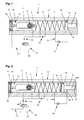
- a drive 1 is shown, with a housing 2, with a displaceable against a compression spring 3 normally-open piston 4, which cooperates with an output shaft 5 for actuating a wing of a door or a window, and wherein the compression spring 3 and the output shaft 5 in a receiving space of the housing 2 are arranged.
- the closing piston 4 divides the receiving space of the housing 2 in a piston chamber 6 and a spring chamber 7.
- the compression spring 3 is supported on the one hand on the closing piston 4 and on the other hand on a further, arranged in the receiving space spring piston 8 from.
- the spring piston 8 is designed as a stepped piston and has a shoulder 8 'with a smaller diameter, which is sealingly guided in a corresponding, tapered region of the receiving space in the housing 2.
- the spring piston 8 separates in the receiving space from a storage space 9 and forms with its approach 8 'from a pressure chamber 10 in the tapered region of the receiving space.
- overflow channels 11, 11 'and 11 are arranged in the housing 2, which are merely outlined in the figures for clarity
- the overflow channels 11, 11' and 11" can be formed in the housing 2, for example by extrusion of the housing 2, or by machining be introduced by drilling.
- the overflow channel 11 ' connects the pressure chamber 10 with the piston chamber 6. Between the spring chamber 7 and the storage space 9 of the overflow 11 is arranged with a hydraulic pump 15.
- a throttle valve 12 and a changeover valve 13 is arranged, wherein when an overflow of hydraulic fluid from the piston chamber 6 in the spring chamber 7, a pressure increase at the throttle valve 12 causes a switching of the switching valve 13, since its control line 14 is connected to the overflow channel 11 ".
- the throttle valve 12 allows a closing damping, i.
- the overflow channel 11 " ends branched and spaced in the receiving space, whereby the behavior of the drive 1 is influenced by the closing piston 4 - depending on the position in the receiving space - closes the openings into the receiving space into Branching arranged throttle valve 12 'allows the setting of an opening damping when opening the door leaf.
- the throttle valves 12, 12 ', the switching valve 13 and the hydraulic pump 15 can be connected to the housing 2 ending at the overflow 11', 11 "or even formed or arranged in the housing 2 itself.
- sensors 16, 16 ' are arranged, which detect the position of the piston 4 and the spring piston 8, and the control of the hydraulic pump 15 are used.
- a donor 17, 17 ' is arranged in the closer piston 4 and in the spring piston 8, which cooperates with sensors 16, 16'.
- the non-contact sensors 16, 16 ' can be configured as reed contact or Hall sensor and the encoders 17, 17' as magnets.
- Fig. 1 the basic position of the drive 1 is shown.
- the wing of the door is closed, and the drive 1 is not yet connected to the mains.
- the closing piston 4 is displaced to the left by the compression spring 3 in the figure.
- the reversing valve 13 is now in its rest position, in which the associated overflow channel 11 "can be flowed through.
- the spring piston 8 is likewise displaced by the compression spring 3 into its rest position - in the figure to the right.
- Fig. 2 shows the drive 1, after it is connected to the mains.
- the sensors 16, 16 ' are initially acted upon by the encoder 17, 17', whereby the hydraulic pump 15 is turned on.
- the hydraulic pump 15 therefore pumps hydraulic fluid from the spring chamber 7 via the overflow channel 11 into the storage chamber 9, whereby a pressure on the spring piston surface 8a is formed, which shifts the spring piston 8 against the force of the compression spring 3.
- the approach 8 'of the spring piston 8 sucks hydraulic fluid from the piston chamber 6 via the overflow 11' in the pressure chamber 10, wherein hydraulic fluid flows from the spring chamber 7 via the overflow 11 "with the throttle valve 12 and the changeover valve 13 in the piston chamber 6 ,
- the hydraulic pump 15 is turned off, as shown in Fig. 2.
- the spring-loaded spring piston 8 generates, with its shoulder surface 8 'a at the shoulder 8' in the pressure chamber 10, a pressure which is present in the piston chamber 6 and in the overflow channel 11 "via the overflow channel 11 '
- the changeover valve 13 switches according to arrow A in FIG. 2 and blocks the overflow channel 11 ", whereby the position of the spring piston 8 according to FIG. 2 is maintained.
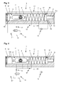
- a position of the drive 1 is shown, wherein the closing piston 4 - in the figure to the right - is displaced by a manual opening of the wing of the door.
- the sensor 16 ' is no longer acted upon by the encoder 17' of the piston 4 and the hydraulic pump 15 is turned off.
- the increased force on the spring piston 8 by compressing the compression spring 3 causes a pressure increase in the pressure chamber 10, which acts through the overflow channel 11 'in the piston chamber 6 and on the control line 14 of the switching valve 13, whereby the overflow channel 11 "remains locked.
- the compression spring 3 is not stretched when opening the wing according to the displacement of the piston 4, since the spring piston 8, on which the Compressive spring 3 is supported, in the same direction, as the closing piston 4 itself.
- the ratio determines the power transmission. This may be constructive provided up to a certain door opening angle, which is usually done during normal inspection, for example, to 85 ° door opening angle.
- the sensors 16 and 16 ' are arranged on the housing 2, which are actuated by the closer piston 4 and the spring piston 8 encoder 17 or 17' depending on the position of the closing piston 4 and spring piston 8 to the Hydraulic pump 15 to control.
- the hydraulic pump is switched on only in the end region of the closing movement of the wing, whereby the complete closing of the wing is supported and the spring bias is effected to opening support.
Landscapes
- Closing And Opening Devices For Wings, And Checks For Wings (AREA)
- Power-Operated Mechanisms For Wings (AREA)
- Actuator (AREA)
Abstract
Description
- Die Erfindung betrifft einen Antrieb für einen Flügel einer Tür oder eines Fensters mit den Merkmalen des Anspruchs 1.
- Aus der
DE 43 23 150 A1 ist ein Türantrieb bekannt, mit einer hydraulischen Schließereinrichtung, mit hydraulischer Kolben-Zylindereinheit und Schließerfeder, mit einer motorischen Öffnereinrichtung mit einer Hydraulikpumpe und einem Elektromotor, wobei beim motorischen Öffnungsvorgang der Druck des Hydraulikmediums angepasst an die momentane Kraft der Schließerfeder geregelt wird. Der Kolben ist im Hydraulikzylinder unter Ausbildung eines Druckraums und eines Drucklosraums verschiebbar geführt, wobei die mit dem Kolben zusammenwirkende Schließerfeder - oder eine auf diese abgestimmte Feder - mit ihrem einen Ende auf dem Kolben und mit ihrem anderen Ende auf einem hydraulischen Druckpolster abgestützt ist. Im Druckraum und im hydraulischen Druckpolster wird der gleiche hydraulische Druck geregelt eingestellt. Zur Bildung des Druckpolsters ist ein Ventilglied angeordnet, welches über unterschiedliche Hydraulikkanäle betätigbar ist. - Der Türantrieb ist aufwändig aufgebaut, da der Hydraulikdruck geregelt an die momentane Kraft der Schließerfeder angepasst wird. Nachteilig weist auch das Ventilglied zur Steuerung mehrere Dichtkanten auf, die mit Hydraulikkanälen zusammenwirken.
- Der Erfindung liegt die Aufgabe zugrunde, einen einfachen, kostengünstigen Antrieb für den Flügel einer Tür oder eines Fensters auszubilden sowie ein Verfahren zur einfaches Steuerung des Antriebs dazu.
- Die Aufgabe wird durch die Merkmale der Ansprüche 1 bzw. 6 gelöst.
- Die Unteransprüche bilden vorteilhafte Ausgestaltungsmöglichkeiten der Erfindung.
- Der erfindungsgemäße Antrieb für einen Flügel einer Tür oder eines Fensters weist einen als Druckfeder ausgebildeten Energiespeicher auf, welcher durch manuelles Öffnen aufgeladen wird und bewirkt, dass der Flügel nach dem Öffnen wieder in seine Geschlossenlage geführt wird. Bei Drehtüren werden dazu Türantriebe eingesetzt, welche über ein gelenkig verbundenes Gestänge oder über einen in einer Gleitschiene durch einen Gleitstein geführten Hebel die Krafteinleitung auf die Tür bewirken. Dabei kann der Türantrieb am Rahmen oder auch auf dem Türblatt festgelegt sein. Der Hebel oder das Gestänge als Kraftübertragungselement stützen sich dabei, entsprechend der gewählten Anordnung, entweder am Türblatt oder am Rahmen ab.
- Der Antrieb weist ein Gehäuse auf, mit einem Aufnahmeraum, in dem die Druckfeder und ein verschiebbarer Schließerkolben angeordnet sind. Der Schließerkolben wirkt mit einer Abtriebswelle zusammen, die mit dem Hebel oder dem Gestänge zur Betätigung des Flügels verbunden ist. Der Aufnahmeraum ist mit einer Hydraulikflüssigkeit befüllt.
- Der Schließerkolben teilt den Aufnahmeraum des Gehäuses in einen Kolbenraum und einen Federraum auf. Im Federraum ist die Druckfeder angeordnet, welche sich einerseits auf dem Schließerkolben und andererseits auf einem weiteren im Aufnahmeraum angeordneten Federkolben abstützt. Der Federkolben ist als Stufenkolben ausgebildet, mit einem Ansatz mit kleinerem Durchmesser, der in einem entsprechend verjüngten Bereich des Aufnahmeraums geführt ist. Der Federkolben trennt im Aufnahmeraum einen Speicherraum ab und bildet mit seinem Ansatz einen Druckraum im verjüngten Bereich des Aufnahmeraums aus. Vorteilhaft ist dem Federkolben keine Ventilfunktion zugeordnet, wodurch ein einfacher Aufbau möglich ist.
- Die verschiedenen Bereiche im Aufnahmeraum sind durch Überströmkanäle miteinander verbunden, wobei die Überströmkanäle in das Gehäuse eingeformt sein können, beispielsweise gleich bei der Herstellung des Gehäuses durch Strangpressen, oder sie werden nachträglich durch eine spanabhebende Bearbeitung durch Bohren oder durch Funkenerosion hergestellt. In den Überströmkanälen können Ventile angeordnet sein, die der Beeinflussung des Verhaltens des Antriebs dienen. Mit den Ventilen kann die Schließgeschwindigkeit des Antriebs oder eine Öffnungsdämpfung eingestellt werden.
- Erfindungsgemäß ist bei dem vorliegenden Antrieb einem der Überströmkanäle eine Hydraulikpumpe zugeordnet, welche es ermöglicht, den Federkolben gegen die Druckfeder hydraulisch zu verschieben, wodurch die Druckfeder vorgespannt wird. Vorteilhaft erfolgt die Steuerung der Hydraulikpumpe über Sensoren, die am Gehäuse angeordnet sind, und welche die Stellung des Schließerkolbens und des Federkolbens erfassen. Die Sensoren können berührungslose Sensoren sein, die als Reedkontakte oder als Hallsensoren ausgebildet sein können, und die mit an den Kolben angeordneten, als Magnete ausgebildeten Gebern zusammenwirken. Die Reedkontakte können elektrisch so mit der Hydraulikpumpe verbunden sein, dass keine weitere Steuereinheit benötigt wird. Dies ist durch eine elektrische Reihenschaltung der Reedkontakte und der Hydraulikpumpe möglich.
- In der Grundstellung des Antriebs, der Geschlossenlage des Türflügels, wird bei der Inbetriebnahme der Antrieb bestromt. Die Sensoren sind durch die Geber beaufschlagt, so dass die Hydraulikpumpe Hydraulikflüssigkeit aus dem Federraum in den Speicherraum des Federkolbens pumpt, wodurch Druck auf die Federkolbenfläche ausgeübt wird, und diese sich gegen die Druckfeder verschiebt, wobei die Druckfeder vorgespannt wird. In den Druckraum strömt über einen Überströmkanal Hydraulikflüssigkeit aus dem Kolbenraum ein. Nach einem bestimmten Verschiebeweg, der durch die Anordnung des Sensors und des zugeordneten Gebers am Federkolben bestimmt ist, wird die Hydraulikpumpe ausgeschaltet. Durch die Anordnung eines Ventils in einem der Überströmkanäle wird gewährleistet, dass der Hydraulikdruck im Speicherraum, und somit die Federvorspannung bestehen bleibt.
- Wird der Türflügel geöffnet, so wird der Schließerkolben gegen die Druckfeder verschoben, wobei sich jedoch gleichzeitig der Federkolben mit verschiebt, da die Hydraulikflüssigkeit aus dem Druckraum in den sich vergrößernden Kolbenraum zurückströmt. Durch diese gleichzeitige Bewegung des Schließerkolbens und des Federkolbens in dieselbe Richtung wird erreicht, dass die Druckfeder durch den Schließerkolben weniger komprimiert wird, als es dem Verschiebeweg des Schließerkolbens entspricht, wodurch ein geringerer Kraftaufwand erforderlich ist. Das Öffnen der Tür wird somit entlastet, so dass die die Tür öffnende Person einen geringeren Widerstand spürt. Abhängig von den konstruktiven Gegebenheiten ist diese Entlastung über einen bestimmten Bereich der Türöffnung möglich, d.h., bis sich der Federkolben vollständig verschoben hat, und alle Hydraulikflüssigkeit aus dem Druckraum in den Kolbenraum geströmt ist. Dieser unterstützte Bereich der Türöffnung kann so gewählt werden, dass dieser einem häufig genutzten Türöffnungswinkel, beispielsweise bis ca. 85° entspricht. Ist ein größerer Türöffnungswinkel erforderlich, beispielsweise beim Transportieren von Lasten, so ist das weitere Öffnen der Tür gegen die Kraft der Druckfeder ohne Entlastung möglich.
- In Schließrichtung wird der Flügel zunächst alleine durch die gespannte Druckfeder beaufschlagt. Im Endbereich, bevor der Flügel ins Schloss fällt, wird dieses Schließen wiederum durch den Antrieb unterstützt, indem die Hydraulikpumpe erneut eingeschaltet wird. Das Einschalten wird durch die Stellung des Schließerkolbens bewirkt, wobei das Einschalten durch die Anordnung des Gebers im Schließerkolben und des zugeordneten Sensors bestimmt wird. Der Federkolben wird gegen die Druckfeder verschoben, wodurch diese komprimiert und der Schließerkolben dadurch mit einer erhöhten Kraft in Schließrichtung beaufschlagt wird. Der Flügel der Tür wird in seine Schließlage geführt, der Federkolben gelangt erneut in die gegen die Druckfeder verschobene Stellung, wodurch die Hydraulikpumpe ausgeschaltet wird, und der Antrieb sich erneut in seiner Grundstellung befindet.
- Die Hydraulikpumpe hat erfindungsgemäß lediglich eine unterstützende Funktion und wird nur im Endbereich der Schließbewegung des Flügels betrieben. Dabei steht eine ausreichende Betriebsdauer zur Verfügung, um den Federkolben zu beaufschlagen. Somit kann eine kleine kostengünstige Hydraulikpumpe mit geringer Leistung eingesetzt werden.
- Im Nachfolgenden wird ein Ausführungsbeispiel in der Zeichnung anhand der Figuren näher erläutert.
-
- Fig. 1
- einen Antrieb bei geschlossenem Flügel, mit unbestromter Hydraulikpumpe;
- Fig. 2
- den Antrieb nach Fig.1 mit bestromter Hydraulikpumpe;
- Fig. 3
- den Antrieb nach Fig. 2, manuell in Öffnungsrichtung betätigt;
- Fig. 4
- den Antrieb nach Fig. 3 in einer weiter geöffneten Stellung.
- In den Figuren ist ein Antrieb 1 gezeigt, mit einem Gehäuse 2, mit einem gegen eine Druckfeder 3 verschiebbaren Schließerkolben 4, welcher mit einer Abtriebswelle 5 zur Betätigung eines Flügels einer Tür oder eines Fensters zusammenwirkt, und wobei die Druckfeder 3 und die Abtriebswelle 5 in einen Aufnahmeraum des Gehäuses 2 angeordnet sind. Der Schließerkolben 4 teilt dabei den Aufnahmeraum des Gehäuses 2 in einen Kolbenraum 6 und einen Federraum 7. Die Druckfeder 3 stützt sich einerseits auf dem Schließerkolben 4 und andererseits auf einem weiteren, im Aufnahmeraum angeordneten Federkolben 8 ab. Der Federkolben 8 ist als Stufenkolben ausgebildet und weist einen Ansatz 8' mit kleinerem Durchmesser auf, der dichtend in einem entsprechenden, verjüngten Bereich des Aufnahmeraums im Gehäuse 2 geführt ist. Der Federkolben 8 trennt im Aufnahmeraum einen Speicherraum 9 ab und bildet mit seinem Ansatz 8' einen Druckraum 10 im verjüngten Bereich des Aufnahmeraums aus.
- Weiterhin sind im Gehäuse 2 Überströmkanäle 11, 11' und 11" angeordnet, die in den Figuren zur Verdeutlichung lediglich skizziert sind. Die Überströmkanäle 11, 11' und 11" können im Gehäuse 2 eingeformt sein, beispielsweise durch Strangpressen des Gehäuses 2, oder spanabhebend durch Bohren eingebracht sein. Der Überströmkanal 11' verbindet dabei den Druckraum 10 mit dem Kolbenraum 6. Zwischen dem Federraum 7 und dem Speicherraum 9 ist der Überströmkanal 11 mit einer Hydraulikpumpe 15 angeordnet.
- Im Überströmkanal 11", welcher den Kolbenraum 6 mit dem Federraum 7 verbindet, ist ein Drosselventil 12 und ein Umschaltventil 13 angeordnet, wobei bei einem Überströmen von Hydraulikflüssigkeit vom Kolbenraum 6 in den Federraum 7 ein Druckanstieg am Drosselventil 12 ein Umschalten des Umschaltventils 13 bewirkt, da dessen Steuerleitung 14 mit dem Überströmkanal 11" verbunden ist. Das Drosselventil 12 ermöglicht eine Schließdämpfung, d.h. eine Einstellbarkeit der Schließgeschwindigkeit des Antriebs 1. Der Überströmkanal 11" endet verzweigt und beabstandet im Aufnahmeraum, wodurch das Verhalten des Antriebs 1 beeinflusst wird, indem der Schließerkolben 4 - je nach Stellung im Aufnahmeraum - die Öffnungen in den Aufnahmeraum hinein verschließt. Das in einer Verzweigungen angeordnete Drosselventil 12' ermöglicht die Einstellung einer Öffnungsdämpfung beim Öffnen des Türflügels.
- Die Drosselventile 12, 12', das Umschaltventil 13 und die Hydraulikpumpe 15 können an die am Gehäuse 2 endenden Überströmkanäle 11', 11" anschließbar oder auch im Gehäuse 2 selbst ausgebildet oder angeordnet sein.
- Im Gehäuse 2 sind Sensoren 16, 16' angeordnet, welche die Stellung des Kolbens 4 und des Federkolbens 8 erfassen, und der Steuerung der Hydraulikpumpe 15 dienen. Dazu ist im Schließerkolben 4 und im Federkolben 8 jeweils ein Geber 17, 17' angeordnet, der mit Sensoren 16, 16' zusammenwirkt. Die berührungslosen Sensoren 16, 16' können als Reedkontakt oder Hallsensor und die Geber 17, 17' als Magnete ausgebildet sein.
- In der Fig. 1 ist die Grundstellung des Antriebs 1 dargestellt. Der Flügel der Tür ist geschlossen, und der Antrieb 1 ist noch nicht mit dem Stromnetz verbunden. Der Schließerkolben 4 ist durch die Druckfeder 3 in der Figur nach links verschoben. Das Umschaltventil 13 ist nun in seiner Ruhelage, in welcher der zugeordnete Überströmkanal 11" durchströmbar ist. Der Federkolben 8 ist ebenfalls durch die Druckfeder 3 in seine Ruhelage - in der Figur nach rechts - verschoben.
- Die Fig. 2 zeigt den Antrieb 1, nachdem dieser an das Stromnetz angeschlossen ist. Die Sensoren 16, 16' sind zunächst durch die Geber 17, 17' beaufschlagt, wodurch die Hydraulikpumpe 15 eingeschaltet ist. Die Hydraulikpumpe 15 pumpt daher Hydraulikflüssigkeit vom Federraum 7 über den Überströmkanal 11 in den Speicherraum 9, wodurch ein Druck an der Federkolbenfläche 8a entsteht, die den Federkolben 8 gegen die Kraft der Druckfeder 3 verschiebt. Der Ansatz 8' des Federkolbens 8 saugt dabei Hydraulikflüssigkeit aus dem Kolbenraum 6 über den Überströmkanal 11' in den Druckraum 10 an, wobei Hydraulikflüssigkeit aus dem Federraum 7 über den Überströmkanal 11" mit dem Drosselventil 12 und über das Umschaltventil 13 in den Kolbenraum 6 nachströmt.
- Gelangt der im Federkolben 8 mit dem angeordnete Geber 17 aus dem Einflussbereich des Sensors 16, wird die Hydraulikpumpe 15 abgeschaltet, wie es in der Fig. 2 gezeigt ist. Der federbelastete Federkolben 8 erzeugt mit seiner Ansatzfläche 8'a am Ansatz 8' im Druckraum 10 einen Druck, der über den Überströmkanal 11' im Kolbenraum 6 und im Überströmkanal 11" ansteht. Dieser Druck wirkt auf die Schließerkolbenfläche 4a und auf die Steuerleitung 14 des Umschaltventils 13 ein. Dadurch schaltet das Umschaltventil 13 gemäß Pfeil A in Fig. 2 um und sperrt den Überströmkanal 11",wodurch die Stellung des Federkolbens 8 gemäß Fig. 2 erhalten bleibt.
- In der Fig. 3 ist eine Stellung des Antriebs 1 dargestellt, wobei der Schließerkolben 4 - in der Figur nach rechts - durch ein manuelles Öffnen des Flügels der Tür verschoben ist. Der Sensor 16' ist nicht mehr durch den Geber 17' des Kolbens 4 beaufschlagt und die Hydraulikpumpe 15 ist ausgeschaltet.
- Die angestiegene Kraftwirkung auf den Federkolben 8 durch das Komprimieren der Druckfeder 3 bewirkt einen Druckanstieg im Druckraum 10, der durch den Überstromkanal 11' auch im Kolbenraum 6 und weiter auf die Steuerleitung 14 des Umschaltventils 13 wirkt, wodurch der Überströmkanal 11" weiterhin gesperrt bleibt.
- Die Druckfeder 3 wird beim Öffnen des Flügels nicht entsprechend dem Verschiebeweg des Kolbens 4 gespannt, da sich der Federkolben 8, auf dem sich die Druckfeder 3 abstützt, in der selben Richtung verschiebt, wie der Schließerkolben 4 selbst. Somit kommt es zu einer Entlastung der am Flügel der Tür aufzuwendenden Kraft durch die unterschiedliche Flächengröße der Schließerkolbenfläche 4a und der Ansatzfläche 8'a, wobei deren Verhältnis die Kraftübersetzung bestimmt. Dies kann konstruktiv bis zu einem bestimmten Türöffnungswinkel vorgesehen sein, welcher üblicherweise bei normaler Begehung vorgenommen wird, beispielsweise bis 85° Türöffnungswinkel.
- In der Fig. 4 ist der vorgesehene Türöffnungswinkel erreicht und der Federkolben 8 vollständig nach rechts verschoben. Die Tür kann weiter gegen die Kraft der Druckfeder 3 geöffnet werden, wobei in diesem Bereich keine Entlastung der Federkraft mehr stattfindet.
- Da durch die Verschiebung des Kolbens 4 der Sensor 16' nicht mehr durch den am Kolben angeordneten Geber 17' beaufschlagt ist, bleibt die Hydraulikpumpe 15 ausgeschaltet, obwohl der Sensor 16 durch den am Federkolben 8 angeordneten Geber 17 wieder beaufschlagt ist.
- Beim Schließen der Tür bewegt sich der durch die Druckfeder 3 beaufschlagte Schließerkolben 4 in die Ausgangsstellung - in den Figuren nach links - zurück. Abhängig von der gewählten Anordnung des Sensors 16' und des Gebers 17' wird die Hydraulikpumpe 15 bei einem Türöffnungswinkel in der Nähe der Schließlage des Türflügels wieder eingeschaltet. Der Federkolben 8 wird durch den Pumpendruck auf die Federkolbenfläche 8a gegen die Druckfeder 3 verschoben, wodurch auf den Schließerkolben 4 die Federkraft und die Kraft durch die Verschiebebewegung des Federkolbens 8 einwirkt. Diese erhöhte Kraftwirkung unterstützt das vollständige Schließen des Türflügels und gewährleistet ein sicheres Schließen der Tür. Dies ist erforderlich, da die Schlossfalle zum vollständigen Schließen in das Schloss zurückgedrückt werden muss, bevor diese in das Schließblech an der Türumrahmung einrasten kann.
- Der Antrieb befindet sich nun erneut in der Ausgangsposition gemäß Fig. 2, wobei der Federkolben 8 durch den Druck im Druckraum 10 beaufschlagt und die Hydraulikpumpe 15 ausgeschaltet ist; das Umschaltventil 13 sperrt den Überströmkanal 11 ". Durch die lediglich unterstützende Funktion der Hydraulikpumpe 15 und deren Betätigung im Endbereich der Schließbewegung des Flügels steht ausreichend Zeit zur Verfügung, um das Überströmen zu bewirken. Es kann daher eine kostengünstige, kleine Hydraulikpumpe 15 mit geringer Leistung verwendet werden.
- Zur einfachen Steuerung des Antriebs 1 sind am Gehäuse 2 die Sensoren 16 bzw. 16' angeordnet, die durch am Schließerkolben 4 und am Federkolben 8 angeordnete Geber 17 bzw. 17' abhängig von der Stellung von Schließerkolben 4 und Federkolben 8 betätigt werden, um die Hydraulikpumpe 15 zu steuern. Durch eine elektrische Reihenschaltung der Sensoren 16, 16' wird erreicht, dass die Hydraulikpumpe lediglich im Endbereich der Schließbewegung des Flügels eingeschaltet ist, wodurch das vollständige Schließen des Flügels unterstützt wird und die Federvorspannung zu Öffnungsunterstützung bewirkt wird.
-
- 1
- Antrieb
- 2
- Gehäuse
- 3
- Druckfeder
- 4
- Schließerkolben
- 4a
- Schließerkolbenfläche
- 5
- Abtriebswelle
- 6
- Kolbenraum
- 7
- Federraum
- 8
- Federkolben
- 8a
- Federkolbenfläche
- 8'
- Ansatz
- 8'a
- Ansatzfläche
- 9
- Speicherraum
- 10
- Druckraum
- 11, 11', 11"
- Überströmkanal
- 12
- Drosselventil Schließgeschwindigkeit
- 12'
- Drosselventil Öffnungsdämpfung
- 13
- Umschaltventil
- 14
- Steuerleitung
- 15
- Hydraulikpumpe
- 16, 16'
- Sensor
- 17, 17'
- Geber
Claims (7)
- Antrieb für einen Flügel einer Tür oder eines Fensters, mit einem Gehäuse mit einem mit einer Hydraulikflüssigkeit gefüllten Aufnahmeraum, und mit einem Schließerkolben und einem Federkolben, zwischen welchen eine Druckfeder angeordnet ist,
wobei der Schließerkolben mit einer Abtriebswelle zur Betätigung des Flügels zusammenwirkt, und der Federkolben zur Vorspannung der Druckfeder dient,
weiterhin mit im Gehäuse angeordneten Überströmkanälen, mit Drosselventilen und Steuerventilen sowie einer Hydraulikpumpe, zur Steuerung des Öffnungs- und Schließverhaltens des Antriebs,
dadurch gekennzeichnet,
dass der Federkolben (8) zwei unterschiedliche Durchmesser aufweist, wobei der größere Durchmesser der Druckfeder (3) zugewandt ist, und ein Ansatz (8') des Federkolbens (8) mit dem kleineren Durchmesser durch einen Überströmkanal (11') mit der von der Druckfeder abgewandten Schließerkolbenfläche (4a) des Schließerkolbens (4), zur Entlastung der Betätigung des Antriebs (1) in Öffnungsrichtung des Flügels, wirkverbunden ist. - Antrieb nach Anspruch 1,
dadurch gekennzeichnet, dass die Hydraulikpumpe (15) ausschließlich zur Betätigung des Federkolbens (8) vorgesehen ist. - Antrieb nach Anspruch 2,
dadurch gekennzeichnet, dass die Hydraulikpumpe (15) mit der Federkolbenfläche (8a) des Federkolbens (8) zusammenwirkt, um den Federkolben (8) gegen die Druckfeder (3) zu verschieben. - Antrieb nach Anspruch 1,
dadurch gekennzeichnet , dass am Gehäuse (2) Sensoren (16) bzw. (16') angeordnet sind, welche mit am Schließerkolben (4) und am Federkolben (8) angeordneten Gebern (17) bzw. (17') zur Steuerung der Hydraulikpumpe (15) zusammenwirken. - Antrieb nach Anspruch 1,
dadurch gekennzeichnet , dass die Ansatzfläche (8'a) durch die Federkraft der Druckfeder (3) auf den Federkolben (8) einen Druck erzeugt, durch den ein Umschaltventil (13) betätigt wird, wodurch ein Überströmkanal (11 ") gesperrt wird. - Verfahren zur Steuerung eines Antriebs für einen Flügel einer Tür oder eines Fensters nach Anspruchs 1
dadurch gekennzeichnet,
dass am Gehäuse (2) angeordnete Sensoren (16) bzw. (16'), durch am Schließerkolben (4) und am Federkolben (8) angeordnete Geber (17) bzw. (17') betätigt, abhängig von der Stellung von Schließerkolben (4) und Federkolben (8) die Hydraulikpumpe (15) steuern. - Verfahren nach Anspruch 6,
dadurch gekennzeichnet , dass die Sensoren (16, 16') und die Hydraulikpumpe (15) durch eine elektrische Reihenschaltung verbunden sind, wodurch im Endbereich der Schließbewegung des Flügels die Hydraulikpumpe (15) eingeschaltet ist, welche ein vollständiges Schließen des Flügels unterstützt sowie die Federvorspannung zur Öffnungsunterstützung bewirkt.
Applications Claiming Priority (1)
| Application Number | Priority Date | Filing Date | Title |
|---|---|---|---|
| DE102006027638A DE102006027638B4 (de) | 2006-06-13 | 2006-06-13 | Antrieb für den Flügel einer Tür oder eines Fensters |
Publications (3)
| Publication Number | Publication Date |
|---|---|
| EP1867825A2 true EP1867825A2 (de) | 2007-12-19 |
| EP1867825A3 EP1867825A3 (de) | 2012-04-04 |
| EP1867825B1 EP1867825B1 (de) | 2015-05-20 |
Family
ID=38515808
Family Applications (1)
| Application Number | Title | Priority Date | Filing Date |
|---|---|---|---|
| EP20070110031 Not-in-force EP1867825B1 (de) | 2006-06-13 | 2007-06-12 | Antrieb für den Flügel einer Tür oder eines Fensters |
Country Status (2)
| Country | Link |
|---|---|
| EP (1) | EP1867825B1 (de) |
| DE (1) | DE102006027638B4 (de) |
Citations (4)
| Publication number | Priority date | Publication date | Assignee | Title |
|---|---|---|---|---|
| DE4323152A1 (de) | 1993-07-10 | 1995-01-12 | Geze Gmbh & Co | Drehtürantrieb |
| DE4323150A1 (de) | 1993-07-10 | 1995-01-12 | Geze Gmbh & Co | Drehtürantrieb |
| WO1999005379A1 (de) | 1997-07-09 | 1999-02-04 | Geze Gmbh & Co. | Vorrichtung zum öffnen und/oder schliessen eines flügels einer tür, eines fensters oder dergleichen |
| WO2004106681A1 (de) | 2003-06-03 | 2004-12-09 | Dorma Gmbh + Co. Kg | Hydraulischer türantrieb |
Family Cites Families (1)
| Publication number | Priority date | Publication date | Assignee | Title |
|---|---|---|---|---|
| DE19628377B4 (de) * | 1996-07-13 | 2005-05-04 | Geze Gmbh | Antrieb für einen Tür- oder Fensterflügel |
-
2006
- 2006-06-13 DE DE102006027638A patent/DE102006027638B4/de not_active Expired - Lifetime
-
2007
- 2007-06-12 EP EP20070110031 patent/EP1867825B1/de not_active Not-in-force
Patent Citations (4)
| Publication number | Priority date | Publication date | Assignee | Title |
|---|---|---|---|---|
| DE4323152A1 (de) | 1993-07-10 | 1995-01-12 | Geze Gmbh & Co | Drehtürantrieb |
| DE4323150A1 (de) | 1993-07-10 | 1995-01-12 | Geze Gmbh & Co | Drehtürantrieb |
| WO1999005379A1 (de) | 1997-07-09 | 1999-02-04 | Geze Gmbh & Co. | Vorrichtung zum öffnen und/oder schliessen eines flügels einer tür, eines fensters oder dergleichen |
| WO2004106681A1 (de) | 2003-06-03 | 2004-12-09 | Dorma Gmbh + Co. Kg | Hydraulischer türantrieb |
Also Published As
| Publication number | Publication date |
|---|---|
| DE102006027638B4 (de) | 2010-02-25 |
| DE102006027638A1 (de) | 2007-12-27 |
| EP1867825A3 (de) | 2012-04-04 |
| EP1867825B1 (de) | 2015-05-20 |
Similar Documents
| Publication | Publication Date | Title |
|---|---|---|
| EP2547935B1 (de) | Antrieb mit notschliessfunktion | |
| DE4233994A1 (de) | Hydraulische betaetigungsanordnung | |
| DE102010002625A1 (de) | Hydraulische Stelleinrichtung für einen Türflügel eines Omnibusses | |
| WO1985004700A1 (fr) | Vanne a sieges obliques | |
| EP1828522B1 (de) | Türantrieb, insbesondere drehtürantrieb | |
| DE102010008167B4 (de) | Schieberventil eines Türbetätigers | |
| DE102004064138B4 (de) | Geberzylinder für Kupplungsausrücksysteme | |
| WO2006066665A1 (de) | Türantrieb, insbesondere drehtürantrieb | |
| EP1867825B1 (de) | Antrieb für den Flügel einer Tür oder eines Fensters | |
| DE3102232A1 (de) | Magnetventil | |
| WO2010102979A1 (de) | Rückstellvorrichtung für motorische türantriebe | |
| EP3153647A1 (de) | Vorrichtung und verfahren zur betätigung eines türdrückers | |
| EP2435652B1 (de) | Ventil einer hydraulischen türbetätigungsvorrichtung | |
| DE19607878B4 (de) | Drehtürantrieb | |
| EP2679756A2 (de) | Antrieb zum Öffnen und/oder Schließen eines beweglichen Flügels einer Tür oder eines Fensters sowie Verfahren zum Betrieb dieses Antriebs | |
| EP1004786A2 (de) | Anlaufsteuerung zum Ansteuern einer hydraulischen Kolben-Zylinder-Einheit | |
| DE102012100926A1 (de) | Feststellanordnung für Gleitschiene | |
| DE10361085B4 (de) | Hydraulisch-mechanische Schließfolgeregelung | |
| DE102018216381B4 (de) | Antriebseinheit für einen Schwenk- oder Schiebeflügel und Drehpositionserfassungsverfahren in einer Antriebseinheit | |
| DE19944808C1 (de) | Druckbegrenzungs- und Drucksicherungsventil für Druckluftbremsanlagen von Kraftfahrzeugen | |
| DE19532263B4 (de) | Vorrichtung zur Schließfolgeregelung für zweiflügelige Türen | |
| DE102011078396B4 (de) | Antrieb zum Öffnen und/oder Schließen eines beweglichen Flügels einer Tür oder eines Fensters | |
| DE102004054086B4 (de) | Freigabeeinrichtung | |
| EP2913469B1 (de) | Schließfolgeregelung für eine einen Standflügel und einen Gangflügel aufweisende Tür | |
| EP1620626B2 (de) | Hydraulisch-mechanische schliessfolgerelung |
Legal Events
| Date | Code | Title | Description |
|---|---|---|---|
| PUAI | Public reference made under article 153(3) epc to a published international application that has entered the european phase |
Free format text: ORIGINAL CODE: 0009012 |
|
| AK | Designated contracting states |
Kind code of ref document: A2 Designated state(s): AT BE BG CH CY CZ DE DK EE ES FI FR GB GR HU IE IS IT LI LT LU LV MC MT NL PL PT RO SE SI SK TR |
|
| AX | Request for extension of the european patent |
Extension state: AL BA HR MK YU |
|
| PUAL | Search report despatched |
Free format text: ORIGINAL CODE: 0009013 |
|
| AK | Designated contracting states |
Kind code of ref document: A3 Designated state(s): AT BE BG CH CY CZ DE DK EE ES FI FR GB GR HU IE IS IT LI LT LU LV MC MT NL PL PT RO SE SI SK TR |
|
| AX | Request for extension of the european patent |
Extension state: AL BA HR MK RS |
|
| RIC1 | Information provided on ipc code assigned before grant |
Ipc: E05F 3/12 20060101ALI20120227BHEP Ipc: E05F 3/22 20060101ALI20120227BHEP Ipc: E05F 3/10 20060101AFI20120227BHEP |
|
| 17P | Request for examination filed |
Effective date: 20120905 |
|
| AKX | Designation fees paid |
Designated state(s): AT BE BG CH CY CZ DE DK EE ES FI FR GB GR HU IE IS IT LI LT LU LV MC MT NL PL PT RO SE SI SK TR |
|
| GRAP | Despatch of communication of intention to grant a patent |
Free format text: ORIGINAL CODE: EPIDOSNIGR1 |
|
| INTG | Intention to grant announced |
Effective date: 20141201 |
|
| GRAS | Grant fee paid |
Free format text: ORIGINAL CODE: EPIDOSNIGR3 |
|
| GRAA | (expected) grant |
Free format text: ORIGINAL CODE: 0009210 |
|
| AK | Designated contracting states |
Kind code of ref document: B1 Designated state(s): AT BE BG CH CY CZ DE DK EE ES FI FR GB GR HU IE IS IT LI LT LU LV MC MT NL PL PT RO SE SI SK TR |
|
| REG | Reference to a national code |
Ref country code: GB Ref legal event code: FG4D Free format text: NOT ENGLISH Ref country code: DE Ref legal event code: R081 Ref document number: 502007013937 Country of ref document: DE Owner name: GEZE GMBH, DE Free format text: FORMER OWNER: GEZE GMBH, 71229 LEONBERG, DE |
|
| REG | Reference to a national code |
Ref country code: CH Ref legal event code: EP |
|
| REG | Reference to a national code |
Ref country code: AT Ref legal event code: REF Ref document number: 727850 Country of ref document: AT Kind code of ref document: T Effective date: 20150615 |
|
| REG | Reference to a national code |
Ref country code: IE Ref legal event code: FG4D Free format text: LANGUAGE OF EP DOCUMENT: GERMAN |
|
| REG | Reference to a national code |
Ref country code: DE Ref legal event code: R096 Ref document number: 502007013937 Country of ref document: DE Effective date: 20150625 |
|
| REG | Reference to a national code |
Ref country code: LT Ref legal event code: MG4D |
|
| REG | Reference to a national code |
Ref country code: NL Ref legal event code: MP Effective date: 20150520 |
|
| PG25 | Lapsed in a contracting state [announced via postgrant information from national office to epo] |
Ref country code: PT Free format text: LAPSE BECAUSE OF FAILURE TO SUBMIT A TRANSLATION OF THE DESCRIPTION OR TO PAY THE FEE WITHIN THE PRESCRIBED TIME-LIMIT Effective date: 20150921 Ref country code: FI Free format text: LAPSE BECAUSE OF FAILURE TO SUBMIT A TRANSLATION OF THE DESCRIPTION OR TO PAY THE FEE WITHIN THE PRESCRIBED TIME-LIMIT Effective date: 20150520 Ref country code: LT Free format text: LAPSE BECAUSE OF FAILURE TO SUBMIT A TRANSLATION OF THE DESCRIPTION OR TO PAY THE FEE WITHIN THE PRESCRIBED TIME-LIMIT Effective date: 20150520 Ref country code: ES Free format text: LAPSE BECAUSE OF FAILURE TO SUBMIT A TRANSLATION OF THE DESCRIPTION OR TO PAY THE FEE WITHIN THE PRESCRIBED TIME-LIMIT Effective date: 20150520 |
|
| PG25 | Lapsed in a contracting state [announced via postgrant information from national office to epo] |
Ref country code: GR Free format text: LAPSE BECAUSE OF FAILURE TO SUBMIT A TRANSLATION OF THE DESCRIPTION OR TO PAY THE FEE WITHIN THE PRESCRIBED TIME-LIMIT Effective date: 20150821 Ref country code: BG Free format text: LAPSE BECAUSE OF FAILURE TO SUBMIT A TRANSLATION OF THE DESCRIPTION OR TO PAY THE FEE WITHIN THE PRESCRIBED TIME-LIMIT Effective date: 20150820 Ref country code: IS Free format text: LAPSE BECAUSE OF FAILURE TO SUBMIT A TRANSLATION OF THE DESCRIPTION OR TO PAY THE FEE WITHIN THE PRESCRIBED TIME-LIMIT Effective date: 20150920 Ref country code: LV Free format text: LAPSE BECAUSE OF FAILURE TO SUBMIT A TRANSLATION OF THE DESCRIPTION OR TO PAY THE FEE WITHIN THE PRESCRIBED TIME-LIMIT Effective date: 20150520 |
|
| PG25 | Lapsed in a contracting state [announced via postgrant information from national office to epo] |
Ref country code: IT Free format text: LAPSE BECAUSE OF FAILURE TO SUBMIT A TRANSLATION OF THE DESCRIPTION OR TO PAY THE FEE WITHIN THE PRESCRIBED TIME-LIMIT Effective date: 20150520 Ref country code: DK Free format text: LAPSE BECAUSE OF FAILURE TO SUBMIT A TRANSLATION OF THE DESCRIPTION OR TO PAY THE FEE WITHIN THE PRESCRIBED TIME-LIMIT Effective date: 20150520 Ref country code: EE Free format text: LAPSE BECAUSE OF FAILURE TO SUBMIT A TRANSLATION OF THE DESCRIPTION OR TO PAY THE FEE WITHIN THE PRESCRIBED TIME-LIMIT Effective date: 20150520 |
|
| REG | Reference to a national code |
Ref country code: CH Ref legal event code: PL |
|
| REG | Reference to a national code |
Ref country code: DE Ref legal event code: R097 Ref document number: 502007013937 Country of ref document: DE |
|
| PG25 | Lapsed in a contracting state [announced via postgrant information from national office to epo] |
Ref country code: RO Free format text: LAPSE BECAUSE OF NON-PAYMENT OF DUE FEES Effective date: 20150520 Ref country code: MC Free format text: LAPSE BECAUSE OF FAILURE TO SUBMIT A TRANSLATION OF THE DESCRIPTION OR TO PAY THE FEE WITHIN THE PRESCRIBED TIME-LIMIT Effective date: 20150520 Ref country code: PL Free format text: LAPSE BECAUSE OF FAILURE TO SUBMIT A TRANSLATION OF THE DESCRIPTION OR TO PAY THE FEE WITHIN THE PRESCRIBED TIME-LIMIT Effective date: 20150520 Ref country code: SK Free format text: LAPSE BECAUSE OF FAILURE TO SUBMIT A TRANSLATION OF THE DESCRIPTION OR TO PAY THE FEE WITHIN THE PRESCRIBED TIME-LIMIT Effective date: 20150520 Ref country code: CZ Free format text: LAPSE BECAUSE OF FAILURE TO SUBMIT A TRANSLATION OF THE DESCRIPTION OR TO PAY THE FEE WITHIN THE PRESCRIBED TIME-LIMIT Effective date: 20150520 |
|
| REG | Reference to a national code |
Ref country code: IE Ref legal event code: MM4A |
|
| PLBE | No opposition filed within time limit |
Free format text: ORIGINAL CODE: 0009261 |
|
| STAA | Information on the status of an ep patent application or granted ep patent |
Free format text: STATUS: NO OPPOSITION FILED WITHIN TIME LIMIT |
|
| REG | Reference to a national code |
Ref country code: FR Ref legal event code: ST Effective date: 20160229 |
|
| 26N | No opposition filed |
Effective date: 20160223 |
|
| GBPC | Gb: european patent ceased through non-payment of renewal fee |
Effective date: 20150820 |
|
| PG25 | Lapsed in a contracting state [announced via postgrant information from national office to epo] |
Ref country code: CH Free format text: LAPSE BECAUSE OF NON-PAYMENT OF DUE FEES Effective date: 20150630 Ref country code: LI Free format text: LAPSE BECAUSE OF NON-PAYMENT OF DUE FEES Effective date: 20150630 Ref country code: IE Free format text: LAPSE BECAUSE OF NON-PAYMENT OF DUE FEES Effective date: 20150612 |
|
| PG25 | Lapsed in a contracting state [announced via postgrant information from national office to epo] |
Ref country code: SI Free format text: LAPSE BECAUSE OF FAILURE TO SUBMIT A TRANSLATION OF THE DESCRIPTION OR TO PAY THE FEE WITHIN THE PRESCRIBED TIME-LIMIT Effective date: 20150520 Ref country code: FR Free format text: LAPSE BECAUSE OF NON-PAYMENT OF DUE FEES Effective date: 20150720 |
|
| PG25 | Lapsed in a contracting state [announced via postgrant information from national office to epo] |
Ref country code: GB Free format text: LAPSE BECAUSE OF NON-PAYMENT OF DUE FEES Effective date: 20150820 |
|
| REG | Reference to a national code |
Ref country code: AT Ref legal event code: MM01 Ref document number: 727850 Country of ref document: AT Kind code of ref document: T Effective date: 20150612 |
|
| PG25 | Lapsed in a contracting state [announced via postgrant information from national office to epo] |
Ref country code: AT Free format text: LAPSE BECAUSE OF NON-PAYMENT OF DUE FEES Effective date: 20150612 |
|
| PG25 | Lapsed in a contracting state [announced via postgrant information from national office to epo] |
Ref country code: MT Free format text: LAPSE BECAUSE OF FAILURE TO SUBMIT A TRANSLATION OF THE DESCRIPTION OR TO PAY THE FEE WITHIN THE PRESCRIBED TIME-LIMIT Effective date: 20150520 |
|
| PG25 | Lapsed in a contracting state [announced via postgrant information from national office to epo] |
Ref country code: HU Free format text: LAPSE BECAUSE OF FAILURE TO SUBMIT A TRANSLATION OF THE DESCRIPTION OR TO PAY THE FEE WITHIN THE PRESCRIBED TIME-LIMIT; INVALID AB INITIO Effective date: 20070612 |
|
| PG25 | Lapsed in a contracting state [announced via postgrant information from national office to epo] |
Ref country code: CY Free format text: LAPSE BECAUSE OF FAILURE TO SUBMIT A TRANSLATION OF THE DESCRIPTION OR TO PAY THE FEE WITHIN THE PRESCRIBED TIME-LIMIT Effective date: 20150520 Ref country code: SE Free format text: LAPSE BECAUSE OF FAILURE TO SUBMIT A TRANSLATION OF THE DESCRIPTION OR TO PAY THE FEE WITHIN THE PRESCRIBED TIME-LIMIT Effective date: 20150520 Ref country code: NL Free format text: LAPSE BECAUSE OF FAILURE TO SUBMIT A TRANSLATION OF THE DESCRIPTION OR TO PAY THE FEE WITHIN THE PRESCRIBED TIME-LIMIT Effective date: 20150520 |
|
| PG25 | Lapsed in a contracting state [announced via postgrant information from national office to epo] |
Ref country code: BE Free format text: LAPSE BECAUSE OF NON-PAYMENT OF DUE FEES Effective date: 20150630 |
|
| PG25 | Lapsed in a contracting state [announced via postgrant information from national office to epo] |
Ref country code: TR Free format text: LAPSE BECAUSE OF FAILURE TO SUBMIT A TRANSLATION OF THE DESCRIPTION OR TO PAY THE FEE WITHIN THE PRESCRIBED TIME-LIMIT Effective date: 20150520 |
|
| PG25 | Lapsed in a contracting state [announced via postgrant information from national office to epo] |
Ref country code: LU Free format text: LAPSE BECAUSE OF NON-PAYMENT OF DUE FEES Effective date: 20150612 |
|
| P01 | Opt-out of the competence of the unified patent court (upc) registered |
Effective date: 20230510 |
|
| PGFP | Annual fee paid to national office [announced via postgrant information from national office to epo] |
Ref country code: DE Payment date: 20240630 Year of fee payment: 18 |
|
| REG | Reference to a national code |
Ref country code: DE Ref legal event code: R119 Ref document number: 502007013937 Country of ref document: DE |
|
| PG25 | Lapsed in a contracting state [announced via postgrant information from national office to epo] |
Ref country code: DE Free format text: LAPSE BECAUSE OF NON-PAYMENT OF DUE FEES Effective date: 20260101 |