EP1867397B1 - Spender mit mehreren Pumpen - Google Patents
Spender mit mehreren Pumpen Download PDFInfo
- Publication number
- EP1867397B1 EP1867397B1 EP06290971A EP06290971A EP1867397B1 EP 1867397 B1 EP1867397 B1 EP 1867397B1 EP 06290971 A EP06290971 A EP 06290971A EP 06290971 A EP06290971 A EP 06290971A EP 1867397 B1 EP1867397 B1 EP 1867397B1
- Authority
- EP
- European Patent Office
- Prior art keywords
- dispenser according
- compartments
- return member
- dispenser
- rod
- Prior art date
- Legal status (The legal status is an assumption and is not a legal conclusion. Google has not performed a legal analysis and makes no representation as to the accuracy of the status listed.)
- Not-in-force
Links
- 230000007246 mechanism Effects 0.000 claims abstract description 8
- 125000006850 spacer group Chemical group 0.000 claims abstract description 7
- 239000004606 Fillers/Extenders Substances 0.000 claims 6
- 239000012263 liquid product Substances 0.000 claims 1
- 239000002537 cosmetic Substances 0.000 abstract description 2
- 239000007788 liquid Substances 0.000 abstract description 2
- 239000000047 product Substances 0.000 description 8
- 239000000203 mixture Substances 0.000 description 2
- 238000005070 sampling Methods 0.000 description 2
- 238000007789 sealing Methods 0.000 description 2
- 230000000295 complement effect Effects 0.000 description 1
- 230000006835 compression Effects 0.000 description 1
- 238000007906 compression Methods 0.000 description 1
- 239000000470 constituent Substances 0.000 description 1
- 230000008878 coupling Effects 0.000 description 1
- 238000010168 coupling process Methods 0.000 description 1
- 238000005859 coupling reaction Methods 0.000 description 1
- 238000006073 displacement reaction Methods 0.000 description 1
- 230000000694 effects Effects 0.000 description 1
- 239000012467 final product Substances 0.000 description 1
- 238000002955 isolation Methods 0.000 description 1
- 238000004806 packaging method and process Methods 0.000 description 1
- 230000002093 peripheral effect Effects 0.000 description 1
- 239000000825 pharmaceutical preparation Substances 0.000 description 1
- 229940127557 pharmaceutical product Drugs 0.000 description 1
- 238000011176 pooling Methods 0.000 description 1
- 238000004321 preservation Methods 0.000 description 1
- 239000000126 substance Substances 0.000 description 1
Images


Classifications
-
- B—PERFORMING OPERATIONS; TRANSPORTING
- B05—SPRAYING OR ATOMISING IN GENERAL; APPLYING FLUENT MATERIALS TO SURFACES, IN GENERAL
- B05B—SPRAYING APPARATUS; ATOMISING APPARATUS; NOZZLES
- B05B11/00—Single-unit hand-held apparatus in which flow of contents is produced by the muscular force of the operator at the moment of use
- B05B11/0005—Components or details
- B05B11/0078—Arrangements for separately storing several components
-
- B—PERFORMING OPERATIONS; TRANSPORTING
- B05—SPRAYING OR ATOMISING IN GENERAL; APPLYING FLUENT MATERIALS TO SURFACES, IN GENERAL
- B05B—SPRAYING APPARATUS; ATOMISING APPARATUS; NOZZLES
- B05B11/00—Single-unit hand-held apparatus in which flow of contents is produced by the muscular force of the operator at the moment of use
- B05B11/01—Single-unit hand-held apparatus in which flow of contents is produced by the muscular force of the operator at the moment of use characterised by the means producing the flow
- B05B11/10—Pump arrangements for transferring the contents from the container to a pump chamber by a sucking effect and forcing the contents out through the dispensing nozzle
- B05B11/1081—Arrangements for pumping several liquids or other fluent materials from several containers, e.g. for mixing them at the moment of pumping
- B05B11/1084—Arrangements for pumping several liquids or other fluent materials from several containers, e.g. for mixing them at the moment of pumping each liquid or other fluent material being pumped by a separate pump
-
- B—PERFORMING OPERATIONS; TRANSPORTING
- B05—SPRAYING OR ATOMISING IN GENERAL; APPLYING FLUENT MATERIALS TO SURFACES, IN GENERAL
- B05B—SPRAYING APPARATUS; ATOMISING APPARATUS; NOZZLES
- B05B15/00—Details of spraying plant or spraying apparatus not otherwise provided for; Accessories
- B05B15/30—Dip tubes
Definitions
- the present invention relates to a multi-pump dispenser.
- Multi-pump dispensers are generally intended for dispensing liquid cosmetic or pharmaceutical products consisting of several components. These components are packaged independently in separate compartments of the same tank. This configuration responds to an isolation constraint of the components for reasons of chemical and / or biological incompatibility. Each component is taken from its compartment and delivered by an independent pump dedicated to it.
- These pumps consist, in the traditional way, of a body which is closed, at the bottom, by an intake valve and, at the top, by a stent and / or an exhaust valve and which contains a mechanism to piston cooperating with an elastic return member.
- the WO 98/30332 A2 discloses a dispenser having all the features of the preamble of claim 1.
- the pumps are not necessarily identical. Their capacity as well as their mechanism can be chosen according to the components to be combined to obtain the desired properties and in particular a specific final composition of the product distributed.
- dispensers are therefore expensive because, on the one hand, their complex structure which is adapted to integrate heavy equipment into sampling means and, on the other hand, the cost of the pumps themselves.
- the present invention aims to solve these technical problems by proposing a simplified structure by the use of unique constituent or functional means and in particular by the pooling for the pumps of essential mechanical elements.
- said hoop comprises at least one sealing member with the wall of the compartments.
- said stents are fixed under a cover forming at least one pusher which cooperates with the return member.
- the upper face of said stents comprises a radial groove opening out through an ejection orifice.
- said groove is closed in the upper part by the underside of said cover.
- said shoulders connect centrally to form a single barrel.
- said compartments are cylindrical and arranged in each other in a nested manner.
- said pump bodies are made in one piece with dip tubes immersed in said compartments of the reservoir.
- said stents comprise a lateral skirt slidably capping a piston consisting of an inner liner anchored in the pump body and carrying the inlet valve.
- said liner is traversed by an axial rod whose upper end forms the valve of the exhaust valve.
- said piston consists of a hollow rod capped, in the upper part, by said stent and coupled, in the lower part, to an inverted cup.
- said rod is movable relative to said cup to open the exhaust valve formed at the lower end of said rod.
- said pumps are closed sealingly by sockets engaged in the bodies around the hollow rods and which are secured to each other by means of a plate.
- the dispenser of the invention has a simple and economical structure adapted to the packaging and the simultaneous or successive delivery of the various components of the same product or of several products.
- This structure provides a common platform with functional elements that can be slaved to multiple identical or different sampling means.
- the presence of a single return member without contact with the components of the product makes it possible to establish good conditions of preservation.
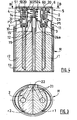
- the distributor shown in the figures comprises a reservoir R equipped with several independent compartments and, here, two compartments r1, r2 semi-cylindrical, each associated with a pump P1, P2.
- Each compartment / pump assembly is adapted to a particular component of a final product to be delivered as a mixture or to separate products (referenced 1 and 2 in the figures).
- the pumps P1, P2 are constituted respectively and generally, a body 1 which is closed, at the bottom, by an inlet valve 10 and, at the top, by a stent 2 and / or a valve of Exhaust 20.
- the bodies 1 contain piston mechanisms 3 cooperating with at least one elastic return member 4.
- the pump bodies 1 are secured to each other in the form of a single ring 11 by a connecting spacer 12 further ensuring the sealed covering of the compartments r1, r2 of the tank R.
- the bodies 1 are of generally cylindro-conical shape and have a flared upper opening which receives the piston mechanism 3.
- Stents 2 are fixed under at least one pusher cover 5 which cooperates with the return member 4.
- Fixing is effected here by snapping the upper part of the stents 2 in a crown 50 of the cover provided with a peripheral projection 51.
- the mechanism of the pump is constituted, in the embodiment of the figure 1 , a piston in the form of a hollow rod 32 capped in the upper part by a stent 2 and coupled in the lower part to an inverted cup 33.
- This coupling allows a slight relative displacement of the rod 32 and the cup 33.
- the cup 33 is intended to slide in contact with the inner wall of the body 1 under the action of the pusher 5 to compress the product in the lower chamber 30 and expel, when the rod 32 is at the end of the race down, via the exhaust valve provided at the lower end of said rod.
- the upper seal is ensured here by a bushing 7 which is engaged in the body 1 around the rod 32 and which is secured to the bushings associated with the other pumps by means of a plate 71 carrying a central sleeve 74 for wedging the rod. return member 4. It is however possible to provide, in a variant not shown, that the plate 71 is provided with a central bore through which passes the central shim sleeve carried, this time, by the spacer 12.
- the piston 3 is in the form of an inner liner 31, anchored internally in the lower part of the body 1 and carrying the intake valve 10.
- the stent 2 here comprises a side skirt 23 slidably capping the piston 3 by producing a compression effect in the upper chamber 30 which is traversed by an axial rod 6 whose conical upper end 60 forms the valve of the valve. exhaust 20.
- the spacer 12 which carries a central sleeve 14 for setting the return member 4.
- the pump bodies are made in one piece with gripping tubes 13, at least partially immersed in the product inside the respective compartments r1, r2 of the reservoir R.
- the return member 4 is formed as a single spring 4 which is mounted outside the body and has no contact with the product components.
- the spacer 12 is provided with at least one sealing member 15 with the wall of the compartments r1, r2.
- the connecting elements 15 are arranged in radial clamping both against the central wall intermediate between the two compartments and on the inner periphery of the side walls of said compartments.
- the compartments are in cylindrical form and arranged in each other in a trundle manner as shown in FIGS. Figures 7 and 8 .
- the hoop 11 is optionally asymmetrical.
- the upper face of the stents 2 comprises a radial groove 21 opening outwards via an ejection orifice 22 which is common to the pumps P1, P2.
- the grooves 21 are sealed at the top by the underside of the cover 5.
- the stents 2 have, in addition, radial shoulders 25 bearing on the single return member 4 and supporting a centering finger 24 of said member.
- the finger 24 extends axially in the sleeve 14 of the collar 11 ( figure 4 ) or in the sleeve 74 of the plate 71 ( figure 1 ) where it is optionally slidably guided and held upwardly by its lower end which carries a harpoon 24a.
- the shoulders 25 are connected centrally forming a single barrel integral with all the pumps.
- the cover 5 is divided into several, and here two, juxtaposed buttons 51, 52, each of which can act alone as a pusher on the single return member 4 to selectively actuate one of the pumps.
- the finger 24 is, itself, constituted of several contiguous and parallel sections which can move axially and independently of each other in the center of the member 4 and in the sleeve 74 (or 14 on figure 4 ).
- the ejection orifice 22 then consists of several cavities with complementary profiles into which the respective grooves of the stents open.
Landscapes
- Containers And Packaging Bodies Having A Special Means To Remove Contents (AREA)
- Media Introduction/Drainage Providing Device (AREA)
- Catching Or Destruction (AREA)
- Closures For Containers (AREA)
Claims (13)
- Spender für flüssige Produkte, umfassend ein Reservoir (R), das mit mehreren unabhängigen Kammern (r1, r2, ...) ausgestattet ist, die jeweils mit einer Pumpe (P1, P2, ...) verknüpft sind, die aus einem Körper (1) besteht, der am unteren Teil von einer Einlassklappe (10) verschlossen wird und am oberen Teil von einer Spannvorrichtung (2) verlängert wird und der einen Kolbenmechanismus enthält (3), der mit einem gemeinsamen elastischen Rückstellorgan (4) zusammenwirkt, wobei die Pumpenkörper in Form einer einzigen Zwinge (11) über einen Verbindungssteg (12), der außerdem die dichte Abdeckung der Reservoirkammern sicherstellt, miteinander fest verbunden sind, wobei die Spannvorrichtungen (2) radiale Ansätze (25) aufweisen, die auf dem Rückstellorgan (4) zur Anlage kommen, dadurch gekennzeichnet, dass die Ansätze einen Zapfen (24) zum Zentrieren des Rückstellorgans (4) tragen, der sich axial und gleitend in einer mittleren Feststellmuffe (14) des Rückstellorgans (4), die von dem Steg getragen wird, erstreckt.
- Spender nach Anspruch 1, dadurch gekennzeichnet, dass die Zwinge (11) mindestens ein Element (15) zur dichten Verbindung mit der Wand der Kammern umfasst.
- Spender nach Anspruch 1 oder 2, dadurch gekennzeichnet, dass die Spannvorrichtungen (2) unter einer Kappe (5) befestigt sind, die mindestens einen Drücker bildet, der mit dem Rückstellorgan (4) zusammenwirkt.
- Spender nach einem der vorhergehenden Ansprüche, dadurch gekennzeichnet, dass die obere Seite der Spannvorrichtungen (2) eine radiale Rille (21) umfasst, die über eine Auswurföffnung (22) nach außen mündet.
- Spender nach Anspruch 3 und 4, dadurch gekennzeichnet, dass die Rille (21) am oberen Teil durch die untere Seite der Kappe (5) geschlossen wird.
- Spender nach einem der vorhergehenden Ansprüche, dadurch gekennzeichnet, dass die Ansätze (25) mittig verbunden werden, indem sie eine einzige Trommel bilden.
- Spender nach einem der vorhergehenden Ansprüche, dadurch gekennzeichnet, dass die Kammern (r1, r2, ...) zylindrisch sind und ineinander einschiebbar angeordnet sind.
- Spender nach einem der vorhergehenden Ansprüche, dadurch gekennzeichnet, dass die Pumpenkörper mit Zapfröhren (13), die in die Kammern des Reservoirs eingetaucht sind, einstückig ausgebildet sind.
- Spender nach einem der vorhergehenden Ansprüche, dadurch gekennzeichnet, dass die Spannvorrichtungen (2) einen seitlichen Mantel (23) umfassen, der gleitend einen Kolben (3) abdeckt, der aus einer Innenhülle (31) besteht, die in dem Pumpenkörper verankert ist und die Einlassklappe (10) trägt.
- Spender nach Anspruch 9, dadurch gekennzeichnet, dass die Hülle (31) von einem Axialstab (6) durchquert wird, dessen oberes Ende (60) das Ventil der Ablassklappe (20) bildet.
- Spender nach einem der vorhergehenden Ansprüche, dadurch gekennzeichnet, dass der Kolben (3) aus einem hohlen Stab (32) besteht, der am oberen Teil von der Spannvorrichtung (2) abgedeckt wird und am unteren Teil mit einer umgekehrten Manschette (33) gekoppelt ist.
- Spender nach Anspruch 11, dadurch gekennzeichnet, dass der Stab (32) im Verhältnis zu der Manschette (33) beweglich ist, um die Ablassklappe (20) zu öffnen, die am unteren Ende des Stabs eingerichtet ist.
- Spender nach Anspruch 11 oder 12, dadurch gekennzeichnet, dass die Pumpen abdichtend durch Hülsen (7) verschlossen sind, die mit den Körpern (1) um die Hohlstäbe (32) herum in Eingriff stehen, und die untereinander mittels einer Platine (71) fest verbunden sind.
Priority Applications (7)
| Application Number | Priority Date | Filing Date | Title |
|---|---|---|---|
| EP06290971A EP1867397B1 (de) | 2006-06-14 | 2006-06-14 | Spender mit mehreren Pumpen |
| AT06290971T ATE477853T1 (de) | 2006-06-14 | 2006-06-14 | Spender mit mehreren pumpen |
| ES06290971T ES2351255T3 (es) | 2006-06-14 | 2006-06-14 | Distribuidor de bombas múltiples. |
| DE602006016253T DE602006016253D1 (de) | 2006-06-14 | 2006-06-14 | Spender mit mehreren Pumpen |
| BRPI0701952-1A BRPI0701952A2 (pt) | 2006-06-14 | 2007-06-12 | distribuidor de produtos lìquidos |
| CN2007101110117A CN101088884B (zh) | 2006-06-14 | 2007-06-13 | 具有多个泵的分配器 |
| US11/763,284 US8225962B2 (en) | 2006-06-14 | 2007-06-14 | Multiple-pump dispenser |
Applications Claiming Priority (1)
| Application Number | Priority Date | Filing Date | Title |
|---|---|---|---|
| EP06290971A EP1867397B1 (de) | 2006-06-14 | 2006-06-14 | Spender mit mehreren Pumpen |
Publications (2)
| Publication Number | Publication Date |
|---|---|
| EP1867397A1 EP1867397A1 (de) | 2007-12-19 |
| EP1867397B1 true EP1867397B1 (de) | 2010-08-18 |
Family
ID=37101353
Family Applications (1)
| Application Number | Title | Priority Date | Filing Date |
|---|---|---|---|
| EP06290971A Not-in-force EP1867397B1 (de) | 2006-06-14 | 2006-06-14 | Spender mit mehreren Pumpen |
Country Status (7)
| Country | Link |
|---|---|
| US (1) | US8225962B2 (de) |
| EP (1) | EP1867397B1 (de) |
| CN (1) | CN101088884B (de) |
| AT (1) | ATE477853T1 (de) |
| BR (1) | BRPI0701952A2 (de) |
| DE (1) | DE602006016253D1 (de) |
| ES (1) | ES2351255T3 (de) |
Families Citing this family (20)
| Publication number | Priority date | Publication date | Assignee | Title |
|---|---|---|---|---|
| KR101037361B1 (ko) * | 2009-03-10 | 2011-05-26 | (주)연우 | 이종내용물을 혼합하여 사용하는 화장품용기 |
| CN102145782B (zh) * | 2011-04-28 | 2012-11-28 | 余姚晟祺塑业有限公司 | 一种揿压式乳液喷头 |
| US8881945B2 (en) * | 2011-09-19 | 2014-11-11 | S.C. Johnson & Son, Inc. | Spray dispenser |
| DE202012004644U1 (de) * | 2012-05-11 | 2013-05-13 | Gerhard Brugger | Sprühspender fûr mehrere Komponenten |
| JP2015534852A (ja) * | 2012-11-05 | 2015-12-07 | スミス アンド ネフュー インコーポレイテッド | 流体送達のための組立体および方法 |
| WO2014077842A1 (en) | 2012-11-19 | 2014-05-22 | Colgate-Palmolive Company | Multi-chamber container |
| KR101446612B1 (ko) * | 2014-05-26 | 2014-10-06 | (주)민진 | 화장품 용기 |
| WO2015191496A1 (en) * | 2014-06-09 | 2015-12-17 | The Procter & Gamble Company | Flushing dispensers for delivering a consistent consumer experience |
| US10435831B1 (en) * | 2014-07-15 | 2019-10-08 | Rita Harry-Ogiste | Fabric treating accessories and associated use thereof |
| US10022741B2 (en) * | 2014-08-22 | 2018-07-17 | Nse Products, Inc. | Selectively actuated fluid dispenser |
| WO2016153870A1 (en) * | 2015-03-20 | 2016-09-29 | VariBlend Dual Dispensing Systems LLC | Bottle interlock |
| BR112019000996A2 (pt) * | 2016-07-18 | 2019-05-14 | Rpc Bramlage Gmbh | dispenser para massas líquidas até pastosas |
| KR20180085253A (ko) * | 2017-01-18 | 2018-07-26 | 강성일 | 이종물질혼합용기 |
| KR101910428B1 (ko) * | 2017-01-23 | 2018-10-22 | (주)연우 | 이종 내용물 토출 용기 |
| USD881714S1 (en) | 2017-07-20 | 2020-04-21 | Lumson S.P.A. | Container |
| WO2020068696A1 (en) * | 2018-09-28 | 2020-04-02 | HCT Group Holdings Limited | Dual dispensing cosmetic container |
| USD1031444S1 (en) * | 2020-10-28 | 2024-06-18 | Lumson S.P.A. | Container |
| CN117136162B (zh) * | 2021-04-06 | 2025-09-30 | 欧莱雅 | 用于储存和分配至少两种化妆品的装置及相关方法 |
| IL285381A (en) * | 2021-08-04 | 2023-03-01 | Yudiva Inc | Double bottle |
| US20250089624A1 (en) * | 2023-09-20 | 2025-03-20 | II Richard P. Steinke | Dual compartment container |
Family Cites Families (8)
| Publication number | Priority date | Publication date | Assignee | Title |
|---|---|---|---|---|
| US4595127A (en) * | 1984-05-21 | 1986-06-17 | Stoody William R | Self-contained fluid pump aerosol dispenser |
| US5509551A (en) * | 1994-07-07 | 1996-04-23 | Terrell, Ii; Robert C. | Beverage container dispensing cap |
| US5590815A (en) * | 1995-07-13 | 1997-01-07 | Monturas S.A. | Minature pump sprayer |
| US6082588A (en) * | 1997-01-10 | 2000-07-04 | Lever Brothers Company, Division Of Conopco, Inc. | Dual compartment package and pumps |
| US6640999B2 (en) * | 2001-11-13 | 2003-11-04 | Unilever Home & Personal Care Usa, Division Of Conopco, Inc. | Dose dispensing pump for dispensing two or more materials |
| EP1531945B1 (de) * | 2002-06-18 | 2009-03-11 | Airspray International B.V. | Ausgabeeinheit |
| US7124914B2 (en) * | 2003-01-08 | 2006-10-24 | Continentalafa Dispensing Company | Dual chamber lotion pump |
| DE20304731U1 (de) * | 2003-03-25 | 2003-06-26 | MegaPlast GmbH & Co. KG, 78052 Villingen-Schwenningen | Dosierpumpe aus Kunststoff |
-
2006
- 2006-06-14 EP EP06290971A patent/EP1867397B1/de not_active Not-in-force
- 2006-06-14 AT AT06290971T patent/ATE477853T1/de not_active IP Right Cessation
- 2006-06-14 DE DE602006016253T patent/DE602006016253D1/de active Active
- 2006-06-14 ES ES06290971T patent/ES2351255T3/es active Active
-
2007
- 2007-06-12 BR BRPI0701952-1A patent/BRPI0701952A2/pt not_active IP Right Cessation
- 2007-06-13 CN CN2007101110117A patent/CN101088884B/zh not_active Expired - Fee Related
- 2007-06-14 US US11/763,284 patent/US8225962B2/en not_active Expired - Fee Related
Also Published As
| Publication number | Publication date |
|---|---|
| BRPI0701952A2 (pt) | 2010-08-31 |
| US8225962B2 (en) | 2012-07-24 |
| ATE477853T1 (de) | 2010-09-15 |
| US20070289999A1 (en) | 2007-12-20 |
| ES2351255T3 (es) | 2011-02-02 |
| CN101088884A (zh) | 2007-12-19 |
| DE602006016253D1 (de) | 2010-09-30 |
| EP1867397A1 (de) | 2007-12-19 |
| CN101088884B (zh) | 2013-03-20 |
Similar Documents
| Publication | Publication Date | Title |
|---|---|---|
| EP1867397B1 (de) | Spender mit mehreren Pumpen | |
| CA2245988C (fr) | Ensemble de conditionnement et de distribution bi-produits | |
| EP1697670B1 (de) | Fluidproduktsprühkopf und diesen sprühkopf umfassende abgabepumpe | |
| FR2943044A1 (fr) | Tete de distribution de produit fluide | |
| WO2014057446A1 (fr) | Valve doseuse de distribution d'un aerosol | |
| WO2002047826A1 (fr) | Micropompe electronique | |
| EP1814672B1 (de) | Ein auslassventil und eine rückstellfeder für eine abgabevorrichtung bildendes flexibles teil | |
| EP1628883B1 (de) | Fluidproduktspender | |
| WO2014072649A1 (fr) | Reservoir de produit fluide | |
| EP1412093B1 (de) | Einen dosierstab bildender spender für flüssige oder gelartige produkte | |
| CA2519525A1 (fr) | Distributeur de produit comprenant une pompe mise en oeuvre par un piston | |
| EP2178649B1 (de) | Ausgabeelement für ein flüssigprodukt | |
| FR2690422A1 (fr) | Dispensateur de produits fluides. | |
| EP2590753B1 (de) | Sprühkopf für einen flüssikeitsspender | |
| FR2852933A1 (fr) | Distributeur de produit fluide. | |
| EP3218602B1 (de) | Manuelle pumpe | |
| FR2708314A1 (fr) | Perfectionnements aux pompes doseuses. | |
| EP3993910B1 (de) | Tragbares spendergerät mit einer airless-pumpe und einer entlüftungspumpe | |
| FR2859464A1 (fr) | Dispositif de distribution a pompe pour un produit fluide, liquide ou pateux | |
| WO2014057448A1 (fr) | Valve doseuse de distribution d'un aérosol | |
| WO2022029374A1 (fr) | Assemblage etanche d'une membrane souple de pompage et d'un embout rigide d'une pompe d'un systeme de distribution sans air d'un produit liquide ou pateux | |
| FR2757786A1 (fr) | Ensemble de conditionnement de liquide, notamment d'un produit cosmetique ou d'un medicament | |
| FR2878002A1 (fr) | Pompe de distribution de produit fluide et distributeur comportant une telle pompe de distribution. |
Legal Events
| Date | Code | Title | Description |
|---|---|---|---|
| PUAI | Public reference made under article 153(3) epc to a published international application that has entered the european phase |
Free format text: ORIGINAL CODE: 0009012 |
|
| AK | Designated contracting states |
Kind code of ref document: A1 Designated state(s): AT BE BG CH CY CZ DE DK EE ES FI FR GB GR HU IE IS IT LI LT LU LV MC NL PL PT RO SE SI SK TR |
|
| AX | Request for extension of the european patent |
Extension state: AL BA HR MK YU |
|
| 17P | Request for examination filed |
Effective date: 20071213 |
|
| 17Q | First examination report despatched |
Effective date: 20080111 |
|
| AKX | Designation fees paid |
Designated state(s): AT BE BG CH CY CZ DE DK EE ES FI FR GB GR HU IE IS IT LI LT LU LV MC NL PL PT RO SE SI SK TR |
|
| GRAP | Despatch of communication of intention to grant a patent |
Free format text: ORIGINAL CODE: EPIDOSNIGR1 |
|
| GRAS | Grant fee paid |
Free format text: ORIGINAL CODE: EPIDOSNIGR3 |
|
| GRAA | (expected) grant |
Free format text: ORIGINAL CODE: 0009210 |
|
| AK | Designated contracting states |
Kind code of ref document: B1 Designated state(s): AT BE BG CH CY CZ DE DK EE ES FI FR GB GR HU IE IS IT LI LT LU LV MC NL PL PT RO SE SI SK TR |
|
| REG | Reference to a national code |
Ref country code: GB Ref legal event code: FG4D Free format text: NOT ENGLISH |
|
| REG | Reference to a national code |
Ref country code: CH Ref legal event code: EP |
|
| REG | Reference to a national code |
Ref country code: IE Ref legal event code: FG4D Free format text: LANGUAGE OF EP DOCUMENT: FRENCH |
|
| REF | Corresponds to: |
Ref document number: 602006016253 Country of ref document: DE Date of ref document: 20100930 Kind code of ref document: P |
|
| REG | Reference to a national code |
Ref country code: NL Ref legal event code: VDEP Effective date: 20100818 |
|
| LTIE | Lt: invalidation of european patent or patent extension |
Effective date: 20100818 |
|
| PG25 | Lapsed in a contracting state [announced via postgrant information from national office to epo] |
Ref country code: AT Free format text: LAPSE BECAUSE OF FAILURE TO SUBMIT A TRANSLATION OF THE DESCRIPTION OR TO PAY THE FEE WITHIN THE PRESCRIBED TIME-LIMIT Effective date: 20100818 Ref country code: FI Free format text: LAPSE BECAUSE OF FAILURE TO SUBMIT A TRANSLATION OF THE DESCRIPTION OR TO PAY THE FEE WITHIN THE PRESCRIBED TIME-LIMIT Effective date: 20100818 Ref country code: LT Free format text: LAPSE BECAUSE OF FAILURE TO SUBMIT A TRANSLATION OF THE DESCRIPTION OR TO PAY THE FEE WITHIN THE PRESCRIBED TIME-LIMIT Effective date: 20100818 |
|
| REG | Reference to a national code |
Ref country code: ES Ref legal event code: FG2A Effective date: 20110121 |
|
| PG25 | Lapsed in a contracting state [announced via postgrant information from national office to epo] |
Ref country code: IS Free format text: LAPSE BECAUSE OF FAILURE TO SUBMIT A TRANSLATION OF THE DESCRIPTION OR TO PAY THE FEE WITHIN THE PRESCRIBED TIME-LIMIT Effective date: 20101218 Ref country code: PT Free format text: LAPSE BECAUSE OF FAILURE TO SUBMIT A TRANSLATION OF THE DESCRIPTION OR TO PAY THE FEE WITHIN THE PRESCRIBED TIME-LIMIT Effective date: 20101220 Ref country code: BG Free format text: LAPSE BECAUSE OF FAILURE TO SUBMIT A TRANSLATION OF THE DESCRIPTION OR TO PAY THE FEE WITHIN THE PRESCRIBED TIME-LIMIT Effective date: 20101118 Ref country code: CY Free format text: LAPSE BECAUSE OF FAILURE TO SUBMIT A TRANSLATION OF THE DESCRIPTION OR TO PAY THE FEE WITHIN THE PRESCRIBED TIME-LIMIT Effective date: 20100818 Ref country code: SI Free format text: LAPSE BECAUSE OF FAILURE TO SUBMIT A TRANSLATION OF THE DESCRIPTION OR TO PAY THE FEE WITHIN THE PRESCRIBED TIME-LIMIT Effective date: 20100818 Ref country code: PL Free format text: LAPSE BECAUSE OF FAILURE TO SUBMIT A TRANSLATION OF THE DESCRIPTION OR TO PAY THE FEE WITHIN THE PRESCRIBED TIME-LIMIT Effective date: 20100818 |
|
| REG | Reference to a national code |
Ref country code: IE Ref legal event code: FD4D |
|
| PG25 | Lapsed in a contracting state [announced via postgrant information from national office to epo] |
Ref country code: NL Free format text: LAPSE BECAUSE OF FAILURE TO SUBMIT A TRANSLATION OF THE DESCRIPTION OR TO PAY THE FEE WITHIN THE PRESCRIBED TIME-LIMIT Effective date: 20100818 Ref country code: GR Free format text: LAPSE BECAUSE OF FAILURE TO SUBMIT A TRANSLATION OF THE DESCRIPTION OR TO PAY THE FEE WITHIN THE PRESCRIBED TIME-LIMIT Effective date: 20101119 Ref country code: SE Free format text: LAPSE BECAUSE OF FAILURE TO SUBMIT A TRANSLATION OF THE DESCRIPTION OR TO PAY THE FEE WITHIN THE PRESCRIBED TIME-LIMIT Effective date: 20100818 Ref country code: LV Free format text: LAPSE BECAUSE OF FAILURE TO SUBMIT A TRANSLATION OF THE DESCRIPTION OR TO PAY THE FEE WITHIN THE PRESCRIBED TIME-LIMIT Effective date: 20100818 |
|
| PG25 | Lapsed in a contracting state [announced via postgrant information from national office to epo] |
Ref country code: DK Free format text: LAPSE BECAUSE OF FAILURE TO SUBMIT A TRANSLATION OF THE DESCRIPTION OR TO PAY THE FEE WITHIN THE PRESCRIBED TIME-LIMIT Effective date: 20100818 Ref country code: IE Free format text: LAPSE BECAUSE OF FAILURE TO SUBMIT A TRANSLATION OF THE DESCRIPTION OR TO PAY THE FEE WITHIN THE PRESCRIBED TIME-LIMIT Effective date: 20100818 |
|
| PG25 | Lapsed in a contracting state [announced via postgrant information from national office to epo] |
Ref country code: CZ Free format text: LAPSE BECAUSE OF FAILURE TO SUBMIT A TRANSLATION OF THE DESCRIPTION OR TO PAY THE FEE WITHIN THE PRESCRIBED TIME-LIMIT Effective date: 20100818 Ref country code: SK Free format text: LAPSE BECAUSE OF FAILURE TO SUBMIT A TRANSLATION OF THE DESCRIPTION OR TO PAY THE FEE WITHIN THE PRESCRIBED TIME-LIMIT Effective date: 20100818 Ref country code: IT Free format text: LAPSE BECAUSE OF FAILURE TO SUBMIT A TRANSLATION OF THE DESCRIPTION OR TO PAY THE FEE WITHIN THE PRESCRIBED TIME-LIMIT Effective date: 20100818 Ref country code: EE Free format text: LAPSE BECAUSE OF FAILURE TO SUBMIT A TRANSLATION OF THE DESCRIPTION OR TO PAY THE FEE WITHIN THE PRESCRIBED TIME-LIMIT Effective date: 20100818 Ref country code: RO Free format text: LAPSE BECAUSE OF FAILURE TO SUBMIT A TRANSLATION OF THE DESCRIPTION OR TO PAY THE FEE WITHIN THE PRESCRIBED TIME-LIMIT Effective date: 20100818 |
|
| PLBE | No opposition filed within time limit |
Free format text: ORIGINAL CODE: 0009261 |
|
| STAA | Information on the status of an ep patent application or granted ep patent |
Free format text: STATUS: NO OPPOSITION FILED WITHIN TIME LIMIT |
|
| 26N | No opposition filed |
Effective date: 20110519 |
|
| REG | Reference to a national code |
Ref country code: DE Ref legal event code: R097 Ref document number: 602006016253 Country of ref document: DE Effective date: 20110519 |
|
| BERE | Be: lapsed |
Owner name: REXAM DISPENSING SMT Effective date: 20110630 |
|
| REG | Reference to a national code |
Ref country code: CH Ref legal event code: PL |
|
| GBPC | Gb: european patent ceased through non-payment of renewal fee |
Effective date: 20110614 |
|
| PG25 | Lapsed in a contracting state [announced via postgrant information from national office to epo] |
Ref country code: BE Free format text: LAPSE BECAUSE OF NON-PAYMENT OF DUE FEES Effective date: 20110630 |
|
| PG25 | Lapsed in a contracting state [announced via postgrant information from national office to epo] |
Ref country code: CH Free format text: LAPSE BECAUSE OF NON-PAYMENT OF DUE FEES Effective date: 20110630 Ref country code: LI Free format text: LAPSE BECAUSE OF NON-PAYMENT OF DUE FEES Effective date: 20110630 |
|
| PG25 | Lapsed in a contracting state [announced via postgrant information from national office to epo] |
Ref country code: GB Free format text: LAPSE BECAUSE OF NON-PAYMENT OF DUE FEES Effective date: 20110614 |
|
| PG25 | Lapsed in a contracting state [announced via postgrant information from national office to epo] |
Ref country code: MC Free format text: LAPSE BECAUSE OF NON-PAYMENT OF DUE FEES Effective date: 20110630 |
|
| PG25 | Lapsed in a contracting state [announced via postgrant information from national office to epo] |
Ref country code: LU Free format text: LAPSE BECAUSE OF NON-PAYMENT OF DUE FEES Effective date: 20110614 |
|
| PG25 | Lapsed in a contracting state [announced via postgrant information from national office to epo] |
Ref country code: TR Free format text: LAPSE BECAUSE OF FAILURE TO SUBMIT A TRANSLATION OF THE DESCRIPTION OR TO PAY THE FEE WITHIN THE PRESCRIBED TIME-LIMIT Effective date: 20100818 |
|
| PG25 | Lapsed in a contracting state [announced via postgrant information from national office to epo] |
Ref country code: HU Free format text: LAPSE BECAUSE OF FAILURE TO SUBMIT A TRANSLATION OF THE DESCRIPTION OR TO PAY THE FEE WITHIN THE PRESCRIBED TIME-LIMIT Effective date: 20100818 |
|
| REG | Reference to a national code |
Ref country code: FR Ref legal event code: CD Owner name: ALBEA LACROST, FR Effective date: 20140513 |
|
| REG | Reference to a national code |
Ref country code: DE Ref legal event code: R081 Ref document number: 602006016253 Country of ref document: DE Owner name: ALBEA LACROST, FR Free format text: FORMER OWNER: REXAM DISPENSING SMT, TOURNUS, FR Effective date: 20140514 |
|
| REG | Reference to a national code |
Ref country code: ES Ref legal event code: PC2A Owner name: ALBEA LACROST, SOCIETE PAR ACTIONS SIMPLIFIEE Effective date: 20140617 |
|
| REG | Reference to a national code |
Ref country code: FR Ref legal event code: CD Owner name: ALBEA LACROST, FR Effective date: 20150316 |
|
| REG | Reference to a national code |
Ref country code: FR Ref legal event code: PLFP Year of fee payment: 10 |
|
| REG | Reference to a national code |
Ref country code: FR Ref legal event code: PLFP Year of fee payment: 11 |
|
| REG | Reference to a national code |
Ref country code: FR Ref legal event code: PLFP Year of fee payment: 12 |
|
| REG | Reference to a national code |
Ref country code: FR Ref legal event code: PLFP Year of fee payment: 13 |
|
| REG | Reference to a national code |
Ref country code: DE Ref legal event code: R082 Ref document number: 602006016253 Country of ref document: DE Representative=s name: ADARES PATENT- UND RECHTSANWAELTE REININGER & , DE |
|
| PGFP | Annual fee paid to national office [announced via postgrant information from national office to epo] |
Ref country code: FR Payment date: 20180626 Year of fee payment: 13 |
|
| PGFP | Annual fee paid to national office [announced via postgrant information from national office to epo] |
Ref country code: ES Payment date: 20180702 Year of fee payment: 13 Ref country code: DE Payment date: 20180627 Year of fee payment: 13 |
|
| REG | Reference to a national code |
Ref country code: DE Ref legal event code: R119 Ref document number: 602006016253 Country of ref document: DE |
|
| PG25 | Lapsed in a contracting state [announced via postgrant information from national office to epo] |
Ref country code: DE Free format text: LAPSE BECAUSE OF NON-PAYMENT OF DUE FEES Effective date: 20200101 |
|
| PG25 | Lapsed in a contracting state [announced via postgrant information from national office to epo] |
Ref country code: FR Free format text: LAPSE BECAUSE OF NON-PAYMENT OF DUE FEES Effective date: 20190630 |
|
| REG | Reference to a national code |
Ref country code: ES Ref legal event code: FD2A Effective date: 20201028 |
|
| PG25 | Lapsed in a contracting state [announced via postgrant information from national office to epo] |
Ref country code: ES Free format text: LAPSE BECAUSE OF NON-PAYMENT OF DUE FEES Effective date: 20190615 |