EP1867397B1 - Multiple pump dispenser - Google Patents
Multiple pump dispenser Download PDFInfo
- Publication number
- EP1867397B1 EP1867397B1 EP06290971A EP06290971A EP1867397B1 EP 1867397 B1 EP1867397 B1 EP 1867397B1 EP 06290971 A EP06290971 A EP 06290971A EP 06290971 A EP06290971 A EP 06290971A EP 1867397 B1 EP1867397 B1 EP 1867397B1
- Authority
- EP
- European Patent Office
- Prior art keywords
- dispenser according
- compartments
- return member
- dispenser
- rod
- Prior art date
- Legal status (The legal status is an assumption and is not a legal conclusion. Google has not performed a legal analysis and makes no representation as to the accuracy of the status listed.)
- Not-in-force
Links
Images


Classifications
-
- B—PERFORMING OPERATIONS; TRANSPORTING
- B05—SPRAYING OR ATOMISING IN GENERAL; APPLYING FLUENT MATERIALS TO SURFACES, IN GENERAL
- B05B—SPRAYING APPARATUS; ATOMISING APPARATUS; NOZZLES
- B05B11/00—Single-unit hand-held apparatus in which flow of contents is produced by the muscular force of the operator at the moment of use
- B05B11/0005—Components or details
- B05B11/0078—Arrangements for separately storing several components
-
- B—PERFORMING OPERATIONS; TRANSPORTING
- B05—SPRAYING OR ATOMISING IN GENERAL; APPLYING FLUENT MATERIALS TO SURFACES, IN GENERAL
- B05B—SPRAYING APPARATUS; ATOMISING APPARATUS; NOZZLES
- B05B11/00—Single-unit hand-held apparatus in which flow of contents is produced by the muscular force of the operator at the moment of use
- B05B11/01—Single-unit hand-held apparatus in which flow of contents is produced by the muscular force of the operator at the moment of use characterised by the means producing the flow
- B05B11/10—Pump arrangements for transferring the contents from the container to a pump chamber by a sucking effect and forcing the contents out through the dispensing nozzle
- B05B11/1081—Arrangements for pumping several liquids or other fluent materials from several containers, e.g. for mixing them at the moment of pumping
- B05B11/1084—Arrangements for pumping several liquids or other fluent materials from several containers, e.g. for mixing them at the moment of pumping each liquid or other fluent material being pumped by a separate pump
-
- B—PERFORMING OPERATIONS; TRANSPORTING
- B05—SPRAYING OR ATOMISING IN GENERAL; APPLYING FLUENT MATERIALS TO SURFACES, IN GENERAL
- B05B—SPRAYING APPARATUS; ATOMISING APPARATUS; NOZZLES
- B05B15/00—Details of spraying plant or spraying apparatus not otherwise provided for; Accessories
- B05B15/30—Dip tubes
Definitions
- the present invention relates to a multi-pump dispenser.
- Multi-pump dispensers are generally intended for dispensing liquid cosmetic or pharmaceutical products consisting of several components. These components are packaged independently in separate compartments of the same tank. This configuration responds to an isolation constraint of the components for reasons of chemical and / or biological incompatibility. Each component is taken from its compartment and delivered by an independent pump dedicated to it.
- These pumps consist, in the traditional way, of a body which is closed, at the bottom, by an intake valve and, at the top, by a stent and / or an exhaust valve and which contains a mechanism to piston cooperating with an elastic return member.
- the WO 98/30332 A2 discloses a dispenser having all the features of the preamble of claim 1.
- the pumps are not necessarily identical. Their capacity as well as their mechanism can be chosen according to the components to be combined to obtain the desired properties and in particular a specific final composition of the product distributed.
- dispensers are therefore expensive because, on the one hand, their complex structure which is adapted to integrate heavy equipment into sampling means and, on the other hand, the cost of the pumps themselves.
- the present invention aims to solve these technical problems by proposing a simplified structure by the use of unique constituent or functional means and in particular by the pooling for the pumps of essential mechanical elements.
- said hoop comprises at least one sealing member with the wall of the compartments.
- said stents are fixed under a cover forming at least one pusher which cooperates with the return member.
- the upper face of said stents comprises a radial groove opening out through an ejection orifice.
- said groove is closed in the upper part by the underside of said cover.
- said shoulders connect centrally to form a single barrel.
- said compartments are cylindrical and arranged in each other in a nested manner.
- said pump bodies are made in one piece with dip tubes immersed in said compartments of the reservoir.
- said stents comprise a lateral skirt slidably capping a piston consisting of an inner liner anchored in the pump body and carrying the inlet valve.
- said liner is traversed by an axial rod whose upper end forms the valve of the exhaust valve.
- said piston consists of a hollow rod capped, in the upper part, by said stent and coupled, in the lower part, to an inverted cup.
- said rod is movable relative to said cup to open the exhaust valve formed at the lower end of said rod.
- said pumps are closed sealingly by sockets engaged in the bodies around the hollow rods and which are secured to each other by means of a plate.
- the dispenser of the invention has a simple and economical structure adapted to the packaging and the simultaneous or successive delivery of the various components of the same product or of several products.
- This structure provides a common platform with functional elements that can be slaved to multiple identical or different sampling means.
- the presence of a single return member without contact with the components of the product makes it possible to establish good conditions of preservation.
- the distributor shown in the figures comprises a reservoir R equipped with several independent compartments and, here, two compartments r1, r2 semi-cylindrical, each associated with a pump P1, P2.
- Each compartment / pump assembly is adapted to a particular component of a final product to be delivered as a mixture or to separate products (referenced 1 and 2 in the figures).
- the pumps P1, P2 are constituted respectively and generally, a body 1 which is closed, at the bottom, by an inlet valve 10 and, at the top, by a stent 2 and / or a valve of Exhaust 20.
- the bodies 1 contain piston mechanisms 3 cooperating with at least one elastic return member 4.
- the pump bodies 1 are secured to each other in the form of a single ring 11 by a connecting spacer 12 further ensuring the sealed covering of the compartments r1, r2 of the tank R.
- the bodies 1 are of generally cylindro-conical shape and have a flared upper opening which receives the piston mechanism 3.
- Stents 2 are fixed under at least one pusher cover 5 which cooperates with the return member 4.
- Fixing is effected here by snapping the upper part of the stents 2 in a crown 50 of the cover provided with a peripheral projection 51.
- the mechanism of the pump is constituted, in the embodiment of the figure 1 , a piston in the form of a hollow rod 32 capped in the upper part by a stent 2 and coupled in the lower part to an inverted cup 33.
- This coupling allows a slight relative displacement of the rod 32 and the cup 33.
- the cup 33 is intended to slide in contact with the inner wall of the body 1 under the action of the pusher 5 to compress the product in the lower chamber 30 and expel, when the rod 32 is at the end of the race down, via the exhaust valve provided at the lower end of said rod.
- the upper seal is ensured here by a bushing 7 which is engaged in the body 1 around the rod 32 and which is secured to the bushings associated with the other pumps by means of a plate 71 carrying a central sleeve 74 for wedging the rod. return member 4. It is however possible to provide, in a variant not shown, that the plate 71 is provided with a central bore through which passes the central shim sleeve carried, this time, by the spacer 12.
- the piston 3 is in the form of an inner liner 31, anchored internally in the lower part of the body 1 and carrying the intake valve 10.
- the stent 2 here comprises a side skirt 23 slidably capping the piston 3 by producing a compression effect in the upper chamber 30 which is traversed by an axial rod 6 whose conical upper end 60 forms the valve of the valve. exhaust 20.
- the spacer 12 which carries a central sleeve 14 for setting the return member 4.
- the pump bodies are made in one piece with gripping tubes 13, at least partially immersed in the product inside the respective compartments r1, r2 of the reservoir R.
- the return member 4 is formed as a single spring 4 which is mounted outside the body and has no contact with the product components.
- the spacer 12 is provided with at least one sealing member 15 with the wall of the compartments r1, r2.
- the connecting elements 15 are arranged in radial clamping both against the central wall intermediate between the two compartments and on the inner periphery of the side walls of said compartments.
- the compartments are in cylindrical form and arranged in each other in a trundle manner as shown in FIGS. Figures 7 and 8 .
- the hoop 11 is optionally asymmetrical.
- the upper face of the stents 2 comprises a radial groove 21 opening outwards via an ejection orifice 22 which is common to the pumps P1, P2.
- the grooves 21 are sealed at the top by the underside of the cover 5.
- the stents 2 have, in addition, radial shoulders 25 bearing on the single return member 4 and supporting a centering finger 24 of said member.
- the finger 24 extends axially in the sleeve 14 of the collar 11 ( figure 4 ) or in the sleeve 74 of the plate 71 ( figure 1 ) where it is optionally slidably guided and held upwardly by its lower end which carries a harpoon 24a.
- the shoulders 25 are connected centrally forming a single barrel integral with all the pumps.
- the cover 5 is divided into several, and here two, juxtaposed buttons 51, 52, each of which can act alone as a pusher on the single return member 4 to selectively actuate one of the pumps.
- the finger 24 is, itself, constituted of several contiguous and parallel sections which can move axially and independently of each other in the center of the member 4 and in the sleeve 74 (or 14 on figure 4 ).
- the ejection orifice 22 then consists of several cavities with complementary profiles into which the respective grooves of the stents open.
Abstract
Description
La présente invention concerne un distributeur à pompes multiples.The present invention relates to a multi-pump dispenser.
Les distributeurs à pompes multiples sont généralement destinés à la délivrance de produits cosmétiques ou pharmaceutiques liquides constitués de plusieurs composants.
Ces composants sont conditionnés de façon indépendante dans des compartiments distincts d'un même réservoir.
Cette configuration répond à une contrainte d'isolement des composants pour des raisons d'incompatibilité chimique et/ou biologique.
Chaque composant est prélevé dans son compartiment et délivré par une pompe indépendante qui lui est dédiée.Multi-pump dispensers are generally intended for dispensing liquid cosmetic or pharmaceutical products consisting of several components.
These components are packaged independently in separate compartments of the same tank.
This configuration responds to an isolation constraint of the components for reasons of chemical and / or biological incompatibility.
Each component is taken from its compartment and delivered by an independent pump dedicated to it.
Ces pompes sont constituées, de manière traditionnelle, d'un corps qui est obturé, en partie basse, par un clapet d'admission et, en partie haute, par un extenseur et/ou un clapet d'échappement et qui renferme un mécanisme à piston coopérant avec un organe de rappel élastique.These pumps consist, in the traditional way, of a body which is closed, at the bottom, by an intake valve and, at the top, by a stent and / or an exhaust valve and which contains a mechanism to piston cooperating with an elastic return member.
Le
Lorsqu'une éjection conjointe des composants est recherchée, l'actionnement des différents mécanismes est effectué simultanément et le mélange des composants intervient alors dans la zone d'échappement des pompes.When a joint ejection of the components is sought, the actuation of the different mechanisms is carried out simultaneously and the mixing of the components then occurs in the exhaust zone of the pumps.
Dans une telle configuration, les pompes ne sont pas nécessairement identiques. Leur capacité ainsi que leur mécanisme peuvent être choisis en fonction des composants à associer pour obtenir les propriétés désirées et notamment une composition finale spécifique du produit distribué.In such a configuration, the pumps are not necessarily identical. Their capacity as well as their mechanism can be chosen according to the components to be combined to obtain the desired properties and in particular a specific final composition of the product distributed.
De tels distributeurs sont donc onéreux du fait, d'une part, de leur structure complexe qui est adaptée pour intégrer un équipement lourd en moyens de prélèvement et, d'autre part, du coût des pompes elles-mêmes.Such dispensers are therefore expensive because, on the one hand, their complex structure which is adapted to integrate heavy equipment into sampling means and, on the other hand, the cost of the pumps themselves.
La présente invention a pour but de résoudre ces problèmes techniques en proposant une structure simplifiée par l'utilisation de moyens constitutifs ou fonctionnels uniques et notamment par la mise en commun pour les pompes d'éléments mécaniques essentiels.The present invention aims to solve these technical problems by proposing a simplified structure by the use of unique constituent or functional means and in particular by the pooling for the pumps of essential mechanical elements.
Ce but est atteint selon l'invention, par un distributeur spécifique selon la revendication 1.This object is achieved according to the invention by a specific distributor according to
Selon une caractéristique avantageuse, ladite frette comporte au moins un élément de raccord étanche avec la paroi des compartiments.According to an advantageous characteristic, said hoop comprises at least one sealing member with the wall of the compartments.
Selon une autre caractéristique, lesdits extenseurs sont fixés sous un capot formant au moins un poussoir qui coopère avec l'organe de rappel.According to another characteristic, said stents are fixed under a cover forming at least one pusher which cooperates with the return member.
Selon encore une autre caractéristique, la face supérieure desdits extenseurs comporte une rainure radiale débouchant à l'extérieur via un orifice d'éjection.According to yet another characteristic, the upper face of said stents comprises a radial groove opening out through an ejection orifice.
De préférence, ladite rainure est fermée en partie supérieure par la face inférieure dudit capot.Preferably, said groove is closed in the upper part by the underside of said cover.
De préférence, lesdits épaulements se raccordent de manière centrale en formant un barillet unique.Preferably, said shoulders connect centrally to form a single barrel.
Selon une autre variante spécifique, lesdits compartiments sont cylindriques et disposés les uns dans les autres de façon gigogne.According to another specific variant, said compartments are cylindrical and arranged in each other in a nested manner.
En outre, il est prévu que lesdits corps de pompe sont réalisés d'une seule pièce avec des tubes de prise immergés dans lesdits compartiments du réservoir.In addition, it is provided that said pump bodies are made in one piece with dip tubes immersed in said compartments of the reservoir.
Selon un premier mode de réalisation des pompes, lesdits extenseurs comportent une jupe latérale coiffant, de manière coulissante, un piston constitué d'une chemise interne ancrée dans le corps de pompe et portant le clapet d'admission.
Dans ce cas, ladite chemise est traversée par une tige axiale dont l'extrémité supérieure forme la soupape du clapet d'échappement.According to a first embodiment of the pumps, said stents comprise a lateral skirt slidably capping a piston consisting of an inner liner anchored in the pump body and carrying the inlet valve.
In this case, said liner is traversed by an axial rod whose upper end forms the valve of the exhaust valve.
Selon un autre mode de réalisation, ledit piston est constitué d'une tige creuse coiffée, en partie supérieure, par ledit extenseur et couplée, en partie inférieure, à une coupelle inversée.
Dans cet autre cas, ladite tige est mobile relativement à ladite coupelle pour ouvrir le clapet d'échappement ménagé à l'extrémité inférieure de ladite tige.According to another embodiment, said piston consists of a hollow rod capped, in the upper part, by said stent and coupled, in the lower part, to an inverted cup.
In this other case, said rod is movable relative to said cup to open the exhaust valve formed at the lower end of said rod.
Selon une variante préférentielle de ce dernier mode, lesdites pompes sont obturées de manière étanche par des douilles engagées dans les corps autour des tiges creuses et qui sont solidarisées entre elles au moyen d'une platine.According to a preferred variant of the latter mode, said pumps are closed sealingly by sockets engaged in the bodies around the hollow rods and which are secured to each other by means of a plate.
Le distributeur de l'invention présente une structure simple et économique adaptée au conditionnement et à la délivrance simultanée ou successive des différents composants d'un même produit ou de plusieurs produits.
Cette structure offre une plateforme commune avec des éléments fonctionnels susceptibles d'être asservis à de multiples moyens de prélèvement identiques ou différents.
La présence d'un organe de rappel unique sans contact avec les composants du produit permet d'établir de bonnes conditions de conservation.The dispenser of the invention has a simple and economical structure adapted to the packaging and the simultaneous or successive delivery of the various components of the same product or of several products.
This structure provides a common platform with functional elements that can be slaved to multiple identical or different sampling means.
The presence of a single return member without contact with the components of the product makes it possible to establish good conditions of preservation.
L'invention sera mieux comprise à la lecture de la description qui va suivre en référence aux dessins sur lesquels ;
- La
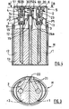
figure 1 représente une vue en coupe verticale d'un premier mode de réalisation du distributeur de l'invention. - La
figure 2 représente une vue extérieure de face du distributeur de lafigure 1 . - La
figure 3 représente une vue en coupe horizontale selon BB du distributeur de lafigure 1 . - La
figure 4 représente une vue en coupe verticale d'une première variante de réalisation du distributeur de l'invention. - Les
figures 5 et 6 représentent des vues respectivement en coupe verticale et extérieure en élévation, d'une seconde variante de réalisation du distributeur de l'invention. - Les
figures 7 et 8 représentent des vues respectivement en coupe verticale et en coupe transversale partielle selon CC d'une troisième variante de réalisation du distributeur de l'invention.
- The
figure 1 represents a vertical sectional view of a first embodiment of the dispenser of the invention. - The
figure 2 represents an external front view of the distributor of thefigure 1 . - The
figure 3 represents a horizontal sectional view according to BB of the distributor of thefigure 1 . - The
figure 4 represents a vertical sectional view of a first embodiment of the dispenser of the invention. - The
Figures 5 and 6 represent views respectively in vertical and external elevational section, of a second embodiment of the dispenser of the invention. - The
Figures 7 and 8 represent views respectively in vertical section and in partial cross-section along CC of a third embodiment of the dispenser of the invention.
Le distributeur représenté sur les figures comprend un réservoir R équipé de plusieurs compartiments indépendants et, ici, de deux compartiments r1, r2 hémicylindriques, associés chacun à une pompe P1, P2.The distributor shown in the figures comprises a reservoir R equipped with several independent compartments and, here, two compartments r1, r2 semi-cylindrical, each associated with a pump P1, P2.
Chaque ensemble compartiment/pompe est adapté à un composant particulier d'un produit final à délivrer sous forme de mélange ou à des produits distincts (référencés 1 et 2 sur les figures).Each compartment / pump assembly is adapted to a particular component of a final product to be delivered as a mixture or to separate products (referenced 1 and 2 in the figures).
Les pompes P1,P2 sont constitués respectivement et de manière générale, d'un corps 1 qui est obturé, en partie basse, par un clapet d'admission 10 et, en partie haute, par un extenseur 2 et/ou un clapet d'échappement 20. Les corps 1 renferment des mécanismes à piston 3 coopérant avec au moins un organe de rappel élastique 4.The pumps P1, P2 are constituted respectively and generally, a
Dans les modes de réalisation de l'invention tels que représentés sur les
Les corps 1 sont de forme générale cylindro-conique et présentent une ouverture supérieure évasée qui reçoit le mécanisme à piston 3.The
Des extenseurs 2 sont fixés sous au moins un capot 5 formant poussoir qui coopère avec l'organe de rappel 4.
La fixation s'opère ici par encliquetage de la partie supérieure des extenseurs 2 dans une couronne 50 du capot pourvue d'une saillie périphérique 51.Fixing is effected here by snapping the upper part of the
Le mécanisme de la pompe est constitué, dans le mode de réalisation de la
Ce couplage autorise un léger déplacement relatif de la tige 32 et de la coupelle 33.
La coupelle 33 est destinée à coulisser au contact avec la paroi interne du corps 1 sous l'action du poussoir 5 pour comprimer le produit dans la chambre basse 30 et l'expulser, lorsque la tige 32 est en fin de course vers le bas, via le clapet d'échappement ménagé à l'extrémité inférieure de ladite tige.
L'étanchéité supérieure est assurée ici par une douille 7 qui est engagée dans le corps 1 autour de la tige 32 et qui est solidarisée avec les douilles associées aux autres pompes au moyen d'une platine 71 portant un manchon central 74 de calage de l'organe de rappel 4.
Il est toutefois possible de prévoir, dans une variante non représentée, que la platine 71 soit pourvue d'un alésage central au travers duquel passe le manchon central de calage porté, cette fois, par l'entretoise 12.The mechanism of the pump is constituted, in the embodiment of the
This coupling allows a slight relative displacement of the
The
The upper seal is ensured here by a bushing 7 which is engaged in the
It is however possible to provide, in a variant not shown, that the
Dans le mode de réalisation de la
L'extenseur 2 comporte ici une jupe latérale 23 coiffant de manière coulissante le piston 3 en produisant un effet de compression dans la chambre haute 30 qui est traversée par une tige axiale 6 dont l'extrémité supérieure conique 60 forme la soupape du clapet d'échappement 20.
C'est ici l'entretoise 12 qui porte un manchon central 14 de calage de l'organe de rappel 4.In the embodiment of the
The
It is here the
De manière générale, les corps de pompe sont réalisés d'une seule pièce avec des tubes 13 de prise, immergés au moins partiellement dans le produit à l'intérieur des compartiments respectifs r1, r2 du réservoir R.In general, the pump bodies are made in one piece with
L'organe de rappel 4 est réalisé sous forme d'un ressort unique 4 qui est monté à l'extérieur des corps et qui n'a aucun contact avec les composants du produit.
L'entretoise 12 est pourvue d'au moins un élément de raccord étanche 15 avec la paroi des compartiments r1, r2.The
The
Dans le mode de réalisation représenté sur les
De préférence et pour obtenir un encombrement minima, les compartiments sont sous forme cylindrique et disposés les uns dans les autres de façon gigogne comme représenté sur les
Dans ce cas la frette 11 est éventuellement asymétrique.Preferably and to obtain a minimum space requirement, the compartments are in cylindrical form and arranged in each other in a trundle manner as shown in FIGS.
In this case the
Comme représentée sur la
Les rainures 21 sont fermées de manière étanche en partie supérieure par la face inférieure du capot 5.The
Les extenseurs 2 présentent, en outre, des épaulements radiaux 25 prenant appui sur l'organe de rappel unique 4 et supportant un doigt 24 de centrage dudit organe. Le doigt 24 s'étend axialement dans le manchon 14 de la frette 11 (
Dans le mode de réalisation représenté sur les
Dans une variante représentée sur les
Dans ce cas, le doigt 24 est, lui-même, constitué de plusieurs sections jointives et parallèles qui peuvent se déplacer axialement et indépendamment les unes des autres au centre de l'organe 4 et dans le manchon 74 (ou 14 sur
Toutefois, l'orifice d'éjection 22 est alors constitué de plusieurs cavités à profils complémentaires dans lesquelles débouchent les rainures respectives des extenseurs.However, the
L'aspect esthétique d'ensemble est quasi identique à celui des variantes à poussoir d'une seule pièce.
En outre, il n'est pas nécessaire que les autres éléments structurels et fonctionnels du distributeur de l'invention soient modifiés par rapport aux modes de réalisation précédemment décrits.The overall aesthetic appearance is almost identical to that of one-piece push-button variants.
In addition, it is not necessary that the other structural and functional elements of the dispenser of the invention are modified with respect to the previously described embodiments.
Claims (13)
- Dispenser of liquid products comprising a container (R) provided with several independent compartments (r1, r2, etc.), each associated to a pump (P1, P2, etc.) constituted of a body (1) sealed, in the lower portion, by an inlet valve (10) and, extended in the upper portion, by an extender (2) and which encloses a piston mechanism (3) cooperating with a common elastic return member (4), said pump bodies being solidly attached to each other in the form of a single shrunk-on ring (11) by a linking spacer (12) providing in addition the sealed covering of said compartments of the container, said extenders (2) having radial shoulders (25) pressing against the return member (4), characterised in that said shoulders support a finger (24) for centring the return member (4) which extends axially and slidingly in a central sleeve (14) for bracing of said return member, carried by said spacer.
- Dispenser according to claim 1 characterised in that said shrunk-on ring (11) comprises at least one element (15) for a sealed connection with the wall of the compartments.
- Dispenser according to claim 1 or 2 characterised in that said extenders (2) are fixed under a cover (5) forming at least one pusher that cooperates with the return member (4).
- Dispenser according to one of the preceding claims characterised in that the upper face of said extenders (2) comprises a radial groove (21) exiting on the exterior via an ejection orifice (22).
- Dispenser according to claims 3 and 4 characterised in that said groove (21) is closed at the upper portion by the lower face of said cover (5).
- Dispenser according to one of the preceding claims characterised in that said shoulders (25) are connected in a central manner by forming a single cylinder.
- Dispenser according to one of the preceding claims characterised in that said compartments (r1, r2, etc.) are cylindrical and arranged together in a nested manner.
- Dispenser according to one of the preceding claims characterised in that said pump bodies are made from a single piece with pick-up tubes (13) immersed in said compartments of the container.
- Dispenser according to one of the preceding claims characterised in that said extenders (2) comprise a lateral skirt (23) covering, slidingly, a piston (3) comprised of an internal liner (31) anchored in the pump body and carrying the inlet valve (10).
- Dispenser according to claim 9 characterised in that said liner (31) is crossed by an axial rod (6) of which the upper end (60) forms the relief valve of the exhaust valve (20).
- Dispenser according to one of the preceding claims characterised in that said piston (3) is constituted of a hollow rod (32) covered, in the upper portion, by said extender (2) and coupled, in the lower portion, to an inverted cup (33).
- Dispenser according to claim 11 characterised in that said rod (32) is mobile relatively to said cup (33) in order to open the exhaust valve (20) arranged at the lower end of said rod.
- Dispenser according to claim 11 or 12 characterised in that said pumps are closed in a sealed manner by bushings (7) engaged in the bodies (1) around the hollow rods (32) and which are solidly attached to one another by means of a plate (71).
Priority Applications (7)
| Application Number | Priority Date | Filing Date | Title |
|---|---|---|---|
| ES06290971T ES2351255T3 (en) | 2006-06-14 | 2006-06-14 | MULTIPLE PUMP DISTRIBUTOR. |
| EP06290971A EP1867397B1 (en) | 2006-06-14 | 2006-06-14 | Multiple pump dispenser |
| DE602006016253T DE602006016253D1 (en) | 2006-06-14 | 2006-06-14 | Dispenser with several pumps |
| AT06290971T ATE477853T1 (en) | 2006-06-14 | 2006-06-14 | MULTIPLE PUMP DISPENSER |
| BRPI0701952-1A BRPI0701952A2 (en) | 2006-06-14 | 2007-06-12 | distributor of liquid products |
| CN2007101110117A CN101088884B (en) | 2006-06-14 | 2007-06-13 | Multiple-pump dispenser |
| US11/763,284 US8225962B2 (en) | 2006-06-14 | 2007-06-14 | Multiple-pump dispenser |
Applications Claiming Priority (1)
| Application Number | Priority Date | Filing Date | Title |
|---|---|---|---|
| EP06290971A EP1867397B1 (en) | 2006-06-14 | 2006-06-14 | Multiple pump dispenser |
Publications (2)
| Publication Number | Publication Date |
|---|---|
| EP1867397A1 EP1867397A1 (en) | 2007-12-19 |
| EP1867397B1 true EP1867397B1 (en) | 2010-08-18 |
Family
ID=37101353
Family Applications (1)
| Application Number | Title | Priority Date | Filing Date |
|---|---|---|---|
| EP06290971A Not-in-force EP1867397B1 (en) | 2006-06-14 | 2006-06-14 | Multiple pump dispenser |
Country Status (7)
| Country | Link |
|---|---|
| US (1) | US8225962B2 (en) |
| EP (1) | EP1867397B1 (en) |
| CN (1) | CN101088884B (en) |
| AT (1) | ATE477853T1 (en) |
| BR (1) | BRPI0701952A2 (en) |
| DE (1) | DE602006016253D1 (en) |
| ES (1) | ES2351255T3 (en) |
Families Citing this family (17)
| Publication number | Priority date | Publication date | Assignee | Title |
|---|---|---|---|---|
| KR101037361B1 (en) * | 2009-03-10 | 2011-05-26 | (주)연우 | A cosmetic case for mixed use of different kinds of contents |
| CN102145782B (en) * | 2011-04-28 | 2012-11-28 | 余姚晟祺塑业有限公司 | Pressing type emulsion spray nozzle |
| WO2013043696A2 (en) * | 2011-09-19 | 2013-03-28 | S.C. Johnson & Son, Inc. | Spray dispenser |
| DE202012004644U1 (en) * | 2012-05-11 | 2013-05-13 | Gerhard Brugger | Spray dispenser for several components |
| US20150265821A1 (en) * | 2012-11-05 | 2015-09-24 | Smith & Nephew, Inc. | Assemblies and methods for fluid delivery |
| WO2014077842A1 (en) | 2012-11-19 | 2014-05-22 | Colgate-Palmolive Company | Multi-chamber container |
| KR101446612B1 (en) * | 2014-05-26 | 2014-10-06 | (주)민진 | Cosmetic vessel |
| CN106457271A (en) * | 2014-06-09 | 2017-02-22 | 宝洁公司 | Flushing dispensers for delivering a consistent consumer experience |
| US10435831B1 (en) * | 2014-07-15 | 2019-10-08 | Rita Harry-Ogiste | Fabric treating accessories and associated use thereof |
| WO2016029104A1 (en) * | 2014-08-22 | 2016-02-25 | Nse Products, Inc. | Selectively actuated fluid dispenser |
| US20160272368A1 (en) * | 2015-03-20 | 2016-09-22 | VariBlend Dual Dispensing Systems LLC | Bottle interlock |
| EP3484628B1 (en) | 2016-07-18 | 2020-08-26 | RPC Bramlage GmbH | Dispenser of liquid or pasty products |
| KR20180085253A (en) * | 2017-01-18 | 2018-07-26 | 강성일 | Receptacle for separately keeping and mixed use of different materials |
| KR101910428B1 (en) * | 2017-01-23 | 2018-10-22 | (주)연우 | Vessel for Dispensing different kind of fluid |
| USD881714S1 (en) * | 2017-07-20 | 2020-04-21 | Lumson S.P.A. | Container |
| WO2020068696A1 (en) * | 2018-09-28 | 2020-04-02 | HCT Group Holdings Limited | Dual dispensing cosmetic container |
| WO2022213250A1 (en) * | 2021-04-06 | 2022-10-13 | L'oreal | Device for storing and dispensing at least two cosmetic products and related method |
Family Cites Families (8)
| Publication number | Priority date | Publication date | Assignee | Title |
|---|---|---|---|---|
| US4595127A (en) * | 1984-05-21 | 1986-06-17 | Stoody William R | Self-contained fluid pump aerosol dispenser |
| US5509551A (en) * | 1994-07-07 | 1996-04-23 | Terrell, Ii; Robert C. | Beverage container dispensing cap |
| US5590815A (en) * | 1995-07-13 | 1997-01-07 | Monturas S.A. | Minature pump sprayer |
| US6082588A (en) * | 1997-01-10 | 2000-07-04 | Lever Brothers Company, Division Of Conopco, Inc. | Dual compartment package and pumps |
| US6640999B2 (en) * | 2001-11-13 | 2003-11-04 | Unilever Home & Personal Care Usa, Division Of Conopco, Inc. | Dose dispensing pump for dispensing two or more materials |
| CN100464870C (en) * | 2002-06-18 | 2009-03-04 | 国际喷雾有限公司 | Dispensing unit |
| US7124914B2 (en) * | 2003-01-08 | 2006-10-24 | Continentalafa Dispensing Company | Dual chamber lotion pump |
| DE20304731U1 (en) * | 2003-03-25 | 2003-06-26 | Megaplast Gmbh & Co Kg | Dosing pump made of plastic |
-
2006
- 2006-06-14 AT AT06290971T patent/ATE477853T1/en not_active IP Right Cessation
- 2006-06-14 ES ES06290971T patent/ES2351255T3/en active Active
- 2006-06-14 EP EP06290971A patent/EP1867397B1/en not_active Not-in-force
- 2006-06-14 DE DE602006016253T patent/DE602006016253D1/en active Active
-
2007
- 2007-06-12 BR BRPI0701952-1A patent/BRPI0701952A2/en not_active IP Right Cessation
- 2007-06-13 CN CN2007101110117A patent/CN101088884B/en not_active Expired - Fee Related
- 2007-06-14 US US11/763,284 patent/US8225962B2/en not_active Expired - Fee Related
Also Published As
| Publication number | Publication date |
|---|---|
| ATE477853T1 (en) | 2010-09-15 |
| EP1867397A1 (en) | 2007-12-19 |
| US20070289999A1 (en) | 2007-12-20 |
| CN101088884A (en) | 2007-12-19 |
| BRPI0701952A2 (en) | 2010-08-31 |
| US8225962B2 (en) | 2012-07-24 |
| CN101088884B (en) | 2013-03-20 |
| DE602006016253D1 (en) | 2010-09-30 |
| ES2351255T3 (en) | 2011-02-02 |
Similar Documents
| Publication | Publication Date | Title |
|---|---|---|
| EP1867397B1 (en) | Multiple pump dispenser | |
| CA2245988C (en) | Twin product packaging and distribution system | |
| EP1697670B1 (en) | Fluid product spray head and distributing pump comprising this spray head | |
| FR2943044A1 (en) | HEAD OF DISTRIBUTION OF FLUID PRODUCT | |
| EP2906484B1 (en) | Metering valve for dispensing an aerosol | |
| FR2817848A1 (en) | ELECTRONIC MICROPUMP | |
| FR2877320A1 (en) | FLUID PRODUCT DISPENSING MEMBER AND FLUID PRODUCT DISPENSING DEVICE PROVIDED WITH SUCH A DISPENSING MEMBER | |
| EP1628883B1 (en) | Fluid product dispenser | |
| EP2916963A1 (en) | Fluid product tank | |
| EP1412093B1 (en) | Liquid or gel product dispenser forming a metering stick | |
| WO2004085286A1 (en) | Product distributor comprising a pump operated by a plunger | |
| FR2690422A1 (en) | Dispenser of fluid products. | |
| EP2178649B1 (en) | Fluid product dispensing member | |
| EP3218602B1 (en) | Manual pump | |
| EP2590753B1 (en) | Spray head for a fluid dispenser | |
| FR2852933A1 (en) | FLUID PRODUCT DISPENSER. | |
| FR2708314A1 (en) | Improvements to metering pumps | |
| EP1590097B1 (en) | Fluid product dispensing element and dispenser comprising one such element | |
| EP2906483A1 (en) | Metering valve for dispensing an aerosol | |
| WO2022029374A1 (en) | Sealed assembly for a flexible pumping membrane and a rigid end piece of a pump of a system for airless dispensing of a liquid or paste product | |
| EP3993910A1 (en) | Portable distributor with a pump without air return and a pump with air return | |
| FR2857340A1 (en) | Fluid product dispensing unit for cosmetic field, has neck joint disposed in contact with lower face of peripheral flange, where axial heights separating face respectively from upper and lower ends of actuating rod and body are equal | |
| FR2757786A1 (en) | LIQUID PACKAGING ASSEMBLY, ESPECIALLY A COSMETIC PRODUCT OR A MEDICINAL PRODUCT | |
| FR2878002A1 (en) | Fluid product e.g. pharmaceutical product, dispensing pump, has cylindrical piston with sleeve having outer diameter equal to inner diameter of pump housing part to limit space located between piston`s outer surface and part`s inner surface |
Legal Events
| Date | Code | Title | Description |
|---|---|---|---|
| PUAI | Public reference made under article 153(3) epc to a published international application that has entered the european phase |
Free format text: ORIGINAL CODE: 0009012 |
|
| AK | Designated contracting states |
Kind code of ref document: A1 Designated state(s): AT BE BG CH CY CZ DE DK EE ES FI FR GB GR HU IE IS IT LI LT LU LV MC NL PL PT RO SE SI SK TR |
|
| AX | Request for extension of the european patent |
Extension state: AL BA HR MK YU |
|
| 17P | Request for examination filed |
Effective date: 20071213 |
|
| 17Q | First examination report despatched |
Effective date: 20080111 |
|
| AKX | Designation fees paid |
Designated state(s): AT BE BG CH CY CZ DE DK EE ES FI FR GB GR HU IE IS IT LI LT LU LV MC NL PL PT RO SE SI SK TR |
|
| GRAP | Despatch of communication of intention to grant a patent |
Free format text: ORIGINAL CODE: EPIDOSNIGR1 |
|
| GRAS | Grant fee paid |
Free format text: ORIGINAL CODE: EPIDOSNIGR3 |
|
| GRAA | (expected) grant |
Free format text: ORIGINAL CODE: 0009210 |
|
| AK | Designated contracting states |
Kind code of ref document: B1 Designated state(s): AT BE BG CH CY CZ DE DK EE ES FI FR GB GR HU IE IS IT LI LT LU LV MC NL PL PT RO SE SI SK TR |
|
| REG | Reference to a national code |
Ref country code: GB Ref legal event code: FG4D Free format text: NOT ENGLISH |
|
| REG | Reference to a national code |
Ref country code: CH Ref legal event code: EP |
|
| REG | Reference to a national code |
Ref country code: IE Ref legal event code: FG4D Free format text: LANGUAGE OF EP DOCUMENT: FRENCH |
|
| REF | Corresponds to: |
Ref document number: 602006016253 Country of ref document: DE Date of ref document: 20100930 Kind code of ref document: P |
|
| REG | Reference to a national code |
Ref country code: NL Ref legal event code: VDEP Effective date: 20100818 |
|
| LTIE | Lt: invalidation of european patent or patent extension |
Effective date: 20100818 |
|
| PG25 | Lapsed in a contracting state [announced via postgrant information from national office to epo] |
Ref country code: AT Free format text: LAPSE BECAUSE OF FAILURE TO SUBMIT A TRANSLATION OF THE DESCRIPTION OR TO PAY THE FEE WITHIN THE PRESCRIBED TIME-LIMIT Effective date: 20100818 Ref country code: FI Free format text: LAPSE BECAUSE OF FAILURE TO SUBMIT A TRANSLATION OF THE DESCRIPTION OR TO PAY THE FEE WITHIN THE PRESCRIBED TIME-LIMIT Effective date: 20100818 Ref country code: LT Free format text: LAPSE BECAUSE OF FAILURE TO SUBMIT A TRANSLATION OF THE DESCRIPTION OR TO PAY THE FEE WITHIN THE PRESCRIBED TIME-LIMIT Effective date: 20100818 |
|
| REG | Reference to a national code |
Ref country code: ES Ref legal event code: FG2A Effective date: 20110121 |
|
| PG25 | Lapsed in a contracting state [announced via postgrant information from national office to epo] |
Ref country code: IS Free format text: LAPSE BECAUSE OF FAILURE TO SUBMIT A TRANSLATION OF THE DESCRIPTION OR TO PAY THE FEE WITHIN THE PRESCRIBED TIME-LIMIT Effective date: 20101218 Ref country code: PT Free format text: LAPSE BECAUSE OF FAILURE TO SUBMIT A TRANSLATION OF THE DESCRIPTION OR TO PAY THE FEE WITHIN THE PRESCRIBED TIME-LIMIT Effective date: 20101220 Ref country code: BG Free format text: LAPSE BECAUSE OF FAILURE TO SUBMIT A TRANSLATION OF THE DESCRIPTION OR TO PAY THE FEE WITHIN THE PRESCRIBED TIME-LIMIT Effective date: 20101118 Ref country code: CY Free format text: LAPSE BECAUSE OF FAILURE TO SUBMIT A TRANSLATION OF THE DESCRIPTION OR TO PAY THE FEE WITHIN THE PRESCRIBED TIME-LIMIT Effective date: 20100818 Ref country code: SI Free format text: LAPSE BECAUSE OF FAILURE TO SUBMIT A TRANSLATION OF THE DESCRIPTION OR TO PAY THE FEE WITHIN THE PRESCRIBED TIME-LIMIT Effective date: 20100818 Ref country code: PL Free format text: LAPSE BECAUSE OF FAILURE TO SUBMIT A TRANSLATION OF THE DESCRIPTION OR TO PAY THE FEE WITHIN THE PRESCRIBED TIME-LIMIT Effective date: 20100818 |
|
| REG | Reference to a national code |
Ref country code: IE Ref legal event code: FD4D |
|
| PG25 | Lapsed in a contracting state [announced via postgrant information from national office to epo] |
Ref country code: NL Free format text: LAPSE BECAUSE OF FAILURE TO SUBMIT A TRANSLATION OF THE DESCRIPTION OR TO PAY THE FEE WITHIN THE PRESCRIBED TIME-LIMIT Effective date: 20100818 Ref country code: GR Free format text: LAPSE BECAUSE OF FAILURE TO SUBMIT A TRANSLATION OF THE DESCRIPTION OR TO PAY THE FEE WITHIN THE PRESCRIBED TIME-LIMIT Effective date: 20101119 Ref country code: SE Free format text: LAPSE BECAUSE OF FAILURE TO SUBMIT A TRANSLATION OF THE DESCRIPTION OR TO PAY THE FEE WITHIN THE PRESCRIBED TIME-LIMIT Effective date: 20100818 Ref country code: LV Free format text: LAPSE BECAUSE OF FAILURE TO SUBMIT A TRANSLATION OF THE DESCRIPTION OR TO PAY THE FEE WITHIN THE PRESCRIBED TIME-LIMIT Effective date: 20100818 |
|
| PG25 | Lapsed in a contracting state [announced via postgrant information from national office to epo] |
Ref country code: DK Free format text: LAPSE BECAUSE OF FAILURE TO SUBMIT A TRANSLATION OF THE DESCRIPTION OR TO PAY THE FEE WITHIN THE PRESCRIBED TIME-LIMIT Effective date: 20100818 Ref country code: IE Free format text: LAPSE BECAUSE OF FAILURE TO SUBMIT A TRANSLATION OF THE DESCRIPTION OR TO PAY THE FEE WITHIN THE PRESCRIBED TIME-LIMIT Effective date: 20100818 |
|
| PG25 | Lapsed in a contracting state [announced via postgrant information from national office to epo] |
Ref country code: CZ Free format text: LAPSE BECAUSE OF FAILURE TO SUBMIT A TRANSLATION OF THE DESCRIPTION OR TO PAY THE FEE WITHIN THE PRESCRIBED TIME-LIMIT Effective date: 20100818 Ref country code: SK Free format text: LAPSE BECAUSE OF FAILURE TO SUBMIT A TRANSLATION OF THE DESCRIPTION OR TO PAY THE FEE WITHIN THE PRESCRIBED TIME-LIMIT Effective date: 20100818 Ref country code: IT Free format text: LAPSE BECAUSE OF FAILURE TO SUBMIT A TRANSLATION OF THE DESCRIPTION OR TO PAY THE FEE WITHIN THE PRESCRIBED TIME-LIMIT Effective date: 20100818 Ref country code: EE Free format text: LAPSE BECAUSE OF FAILURE TO SUBMIT A TRANSLATION OF THE DESCRIPTION OR TO PAY THE FEE WITHIN THE PRESCRIBED TIME-LIMIT Effective date: 20100818 Ref country code: RO Free format text: LAPSE BECAUSE OF FAILURE TO SUBMIT A TRANSLATION OF THE DESCRIPTION OR TO PAY THE FEE WITHIN THE PRESCRIBED TIME-LIMIT Effective date: 20100818 |
|
| PLBE | No opposition filed within time limit |
Free format text: ORIGINAL CODE: 0009261 |
|
| STAA | Information on the status of an ep patent application or granted ep patent |
Free format text: STATUS: NO OPPOSITION FILED WITHIN TIME LIMIT |
|
| 26N | No opposition filed |
Effective date: 20110519 |
|
| REG | Reference to a national code |
Ref country code: DE Ref legal event code: R097 Ref document number: 602006016253 Country of ref document: DE Effective date: 20110519 |
|
| BERE | Be: lapsed |
Owner name: REXAM DISPENSING SMT Effective date: 20110630 |
|
| REG | Reference to a national code |
Ref country code: CH Ref legal event code: PL |
|
| GBPC | Gb: european patent ceased through non-payment of renewal fee |
Effective date: 20110614 |
|
| PG25 | Lapsed in a contracting state [announced via postgrant information from national office to epo] |
Ref country code: BE Free format text: LAPSE BECAUSE OF NON-PAYMENT OF DUE FEES Effective date: 20110630 |
|
| PG25 | Lapsed in a contracting state [announced via postgrant information from national office to epo] |
Ref country code: CH Free format text: LAPSE BECAUSE OF NON-PAYMENT OF DUE FEES Effective date: 20110630 Ref country code: LI Free format text: LAPSE BECAUSE OF NON-PAYMENT OF DUE FEES Effective date: 20110630 |
|
| PG25 | Lapsed in a contracting state [announced via postgrant information from national office to epo] |
Ref country code: GB Free format text: LAPSE BECAUSE OF NON-PAYMENT OF DUE FEES Effective date: 20110614 |
|
| PG25 | Lapsed in a contracting state [announced via postgrant information from national office to epo] |
Ref country code: MC Free format text: LAPSE BECAUSE OF NON-PAYMENT OF DUE FEES Effective date: 20110630 |
|
| PG25 | Lapsed in a contracting state [announced via postgrant information from national office to epo] |
Ref country code: LU Free format text: LAPSE BECAUSE OF NON-PAYMENT OF DUE FEES Effective date: 20110614 |
|
| PG25 | Lapsed in a contracting state [announced via postgrant information from national office to epo] |
Ref country code: TR Free format text: LAPSE BECAUSE OF FAILURE TO SUBMIT A TRANSLATION OF THE DESCRIPTION OR TO PAY THE FEE WITHIN THE PRESCRIBED TIME-LIMIT Effective date: 20100818 |
|
| PG25 | Lapsed in a contracting state [announced via postgrant information from national office to epo] |
Ref country code: HU Free format text: LAPSE BECAUSE OF FAILURE TO SUBMIT A TRANSLATION OF THE DESCRIPTION OR TO PAY THE FEE WITHIN THE PRESCRIBED TIME-LIMIT Effective date: 20100818 |
|
| REG | Reference to a national code |
Ref country code: FR Ref legal event code: CD Owner name: ALBEA LACROST, FR Effective date: 20140513 |
|
| REG | Reference to a national code |
Ref country code: DE Ref legal event code: R081 Ref document number: 602006016253 Country of ref document: DE Owner name: ALBEA LACROST, FR Free format text: FORMER OWNER: REXAM DISPENSING SMT, TOURNUS, FR Effective date: 20140514 |
|
| REG | Reference to a national code |
Ref country code: ES Ref legal event code: PC2A Owner name: ALBEA LACROST, SOCIETE PAR ACTIONS SIMPLIFIEE Effective date: 20140617 |
|
| REG | Reference to a national code |
Ref country code: FR Ref legal event code: CD Owner name: ALBEA LACROST, FR Effective date: 20150316 |
|
| REG | Reference to a national code |
Ref country code: FR Ref legal event code: PLFP Year of fee payment: 10 |
|
| REG | Reference to a national code |
Ref country code: FR Ref legal event code: PLFP Year of fee payment: 11 |
|
| REG | Reference to a national code |
Ref country code: FR Ref legal event code: PLFP Year of fee payment: 12 |
|
| REG | Reference to a national code |
Ref country code: FR Ref legal event code: PLFP Year of fee payment: 13 |
|
| REG | Reference to a national code |
Ref country code: DE Ref legal event code: R082 Ref document number: 602006016253 Country of ref document: DE Representative=s name: ADARES PATENT- UND RECHTSANWAELTE REININGER & , DE |
|
| PGFP | Annual fee paid to national office [announced via postgrant information from national office to epo] |
Ref country code: FR Payment date: 20180626 Year of fee payment: 13 |
|
| PGFP | Annual fee paid to national office [announced via postgrant information from national office to epo] |
Ref country code: ES Payment date: 20180702 Year of fee payment: 13 Ref country code: DE Payment date: 20180627 Year of fee payment: 13 |
|
| REG | Reference to a national code |
Ref country code: DE Ref legal event code: R119 Ref document number: 602006016253 Country of ref document: DE |
|
| PG25 | Lapsed in a contracting state [announced via postgrant information from national office to epo] |
Ref country code: DE Free format text: LAPSE BECAUSE OF NON-PAYMENT OF DUE FEES Effective date: 20200101 |
|
| PG25 | Lapsed in a contracting state [announced via postgrant information from national office to epo] |
Ref country code: FR Free format text: LAPSE BECAUSE OF NON-PAYMENT OF DUE FEES Effective date: 20190630 |
|
| REG | Reference to a national code |
Ref country code: ES Ref legal event code: FD2A Effective date: 20201028 |
|
| PG25 | Lapsed in a contracting state [announced via postgrant information from national office to epo] |
Ref country code: ES Free format text: LAPSE BECAUSE OF NON-PAYMENT OF DUE FEES Effective date: 20190615 |