EP3993910B1 - Tragbares spendergerät mit einer airless-pumpe und einer entlüftungspumpe - Google Patents
Tragbares spendergerät mit einer airless-pumpe und einer entlüftungspumpe Download PDFInfo
- Publication number
- EP3993910B1 EP3993910B1 EP20735011.7A EP20735011A EP3993910B1 EP 3993910 B1 EP3993910 B1 EP 3993910B1 EP 20735011 A EP20735011 A EP 20735011A EP 3993910 B1 EP3993910 B1 EP 3993910B1
- Authority
- EP
- European Patent Office
- Prior art keywords
- dispenser
- pump
- pusher
- dispensing
- nozzle
- Prior art date
- Legal status (The legal status is an assumption and is not a legal conclusion. Google has not performed a legal analysis and makes no representation as to the accuracy of the status listed.)
- Active
Links
Images


Classifications
-
- A—HUMAN NECESSITIES
- A45—HAND OR TRAVELLING ARTICLES
- A45D—HAIRDRESSING OR SHAVING EQUIPMENT; EQUIPMENT FOR COSMETICS OR COSMETIC TREATMENTS, e.g. FOR MANICURING OR PEDICURING
- A45D34/00—Containers or accessories specially adapted for handling liquid toiletry or cosmetic substances, e.g. perfumes
-
- B—PERFORMING OPERATIONS; TRANSPORTING
- B05—SPRAYING OR ATOMISING IN GENERAL; APPLYING FLUENT MATERIALS TO SURFACES, IN GENERAL
- B05B—SPRAYING APPARATUS; ATOMISING APPARATUS; NOZZLES
- B05B11/00—Single-unit hand-held apparatus in which flow of contents is produced by the muscular force of the operator at the moment of use
- B05B11/01—Single-unit hand-held apparatus in which flow of contents is produced by the muscular force of the operator at the moment of use characterised by the means producing the flow
- B05B11/02—Membranes or pistons acting on the contents inside the container, e.g. follower pistons
- B05B11/026—Membranes separating the content remaining in the container from the atmospheric air to compensate underpressure inside the container
-
- B—PERFORMING OPERATIONS; TRANSPORTING
- B05—SPRAYING OR ATOMISING IN GENERAL; APPLYING FLUENT MATERIALS TO SURFACES, IN GENERAL
- B05B—SPRAYING APPARATUS; ATOMISING APPARATUS; NOZZLES
- B05B11/00—Single-unit hand-held apparatus in which flow of contents is produced by the muscular force of the operator at the moment of use
- B05B11/01—Single-unit hand-held apparatus in which flow of contents is produced by the muscular force of the operator at the moment of use characterised by the means producing the flow
- B05B11/10—Pump arrangements for transferring the contents from the container to a pump chamber by a sucking effect and forcing the contents out through the dispensing nozzle
- B05B11/1001—Piston pumps
- B05B11/1023—Piston pumps having an outlet valve opened by deformation or displacement of the piston relative to its actuating stem
-
- B—PERFORMING OPERATIONS; TRANSPORTING
- B05—SPRAYING OR ATOMISING IN GENERAL; APPLYING FLUENT MATERIALS TO SURFACES, IN GENERAL
- B05B—SPRAYING APPARATUS; ATOMISING APPARATUS; NOZZLES
- B05B11/00—Single-unit hand-held apparatus in which flow of contents is produced by the muscular force of the operator at the moment of use
- B05B11/01—Single-unit hand-held apparatus in which flow of contents is produced by the muscular force of the operator at the moment of use characterised by the means producing the flow
- B05B11/10—Pump arrangements for transferring the contents from the container to a pump chamber by a sucking effect and forcing the contents out through the dispensing nozzle
- B05B11/1042—Components or details
- B05B11/1052—Actuation means
-
- B—PERFORMING OPERATIONS; TRANSPORTING
- B05—SPRAYING OR ATOMISING IN GENERAL; APPLYING FLUENT MATERIALS TO SURFACES, IN GENERAL
- B05B—SPRAYING APPARATUS; ATOMISING APPARATUS; NOZZLES
- B05B11/00—Single-unit hand-held apparatus in which flow of contents is produced by the muscular force of the operator at the moment of use
- B05B11/01—Single-unit hand-held apparatus in which flow of contents is produced by the muscular force of the operator at the moment of use characterised by the means producing the flow
- B05B11/10—Pump arrangements for transferring the contents from the container to a pump chamber by a sucking effect and forcing the contents out through the dispensing nozzle
- B05B11/1081—Arrangements for pumping several liquids or other fluent materials from several containers, e.g. for mixing them at the moment of pumping
- B05B11/1084—Arrangements for pumping several liquids or other fluent materials from several containers, e.g. for mixing them at the moment of pumping each liquid or other fluent material being pumped by a separate pump
-
- A—HUMAN NECESSITIES
- A45—HAND OR TRAVELLING ARTICLES
- A45D—HAIRDRESSING OR SHAVING EQUIPMENT; EQUIPMENT FOR COSMETICS OR COSMETIC TREATMENTS, e.g. FOR MANICURING OR PEDICURING
- A45D2200/00—Details not otherwise provided for in A45D
- A45D2200/05—Details of containers
- A45D2200/054—Means for supplying liquid to the outlet of the container
- A45D2200/055—Piston or plunger for supplying the liquid to the applicator
-
- A—HUMAN NECESSITIES
- A45—HAND OR TRAVELLING ARTICLES
- A45D—HAIRDRESSING OR SHAVING EQUIPMENT; EQUIPMENT FOR COSMETICS OR COSMETIC TREATMENTS, e.g. FOR MANICURING OR PEDICURING
- A45D2200/00—Details not otherwise provided for in A45D
- A45D2200/05—Details of containers
- A45D2200/058—Means for mixing different substances prior to application
Definitions
- the invention relates to a portable dispenser for several fluid products in parallel to constitute a mixture, for example of several cosmetic body care products, in particular facial care, makeup or perfumery, and/or several pharmaceutical products.
- fluid products liquid products, as well as creams, gels and pasty products which are sufficiently malleable to be distributed using pumps.
- a dispenser for one or more fluid or pasty products comprising a dispenser body, a dispensing head fixed relative to the dispenser body, comprising two dispensing orifices, and a pumping assembly comprising one two pumps, each connected to one of the distribution orifices, and each provided with a tubular nozzle defining an ejection axis passing through the associated distribution orifice, the ejection axes being parallel to a reference axis of the distributor and spaced apart 'from one another, the nozzles being movable in translation relative to the distributor body parallel to the ejection axes.
- a rotating intermediate ring is interposed between the head and the body of the distributor.
- the intermediate ring is guided in rotation and fixed in translation relative to the distributor body around the reference axis of the distributor.
- a kinematic connection between the rotating intermediate ring and the two nozzles makes it possible to transform a rotational movement without translation of the rotating ring relative to the distributor body around the reference axis of the distributor into a translational movement without rotation of the nozzle.
- the first pump and the nozzle of the second pump relative to the distributor body parallel to the reference axis of the distributor.
- This kinematic connection comprises a pusher interposed between the pumping assembly and the rotating intermediate ring, the pusher being linked to the distributor body by a slide connection capable of guiding a translation movement without rotation of the pusher relative to the distributor body.
- the pusher is capable of pressing on the nozzles of the two pumps when the intermediate ring rotates relative to the distributor body around the reference axis of the distributor.
- the pusher has two parallel distribution conduits, each for channeling the fluid escaping from one of the nozzles towards the associated distribution orifice.
- the dispensing head forms a flared cup which allows the user to mix the two fluids in order to obtain the desired final product.
- the operation of the distributor can be considered satisfactory if neither pump requires priming, or if both pumps require a priming and pressurization cycle. We are then assured that from the first use, the distributor will distribute the two products in the desired proportion. If, on the other hand, only one of the two pumps requires priming, the first pumping cycle will not be satisfactory, insofar as only one product, that from the pump not requiring priming, will be delivered.
- the ergonomics of using such a dispenser is not entirely satisfactory, to the extent that the user must hold the body or head of the dispenser with one hand and access the ring with the other. intermediate, which is located under the flared head.
- the device is not suitable for the distribution of products coming from pumps not having the same volume or having different priming characteristics. It is therefore not suitable for the distribution of products with different flow characteristics, for example different viscosities, densities or surface tensions, requiring different types of pumps, or for products one of which is sensitive in contact with air and the other not.
- the invention aims to remedy at least some of the drawbacks of the state of the art and to propose a portable dispenser with several pumps, suitable for the simultaneous distribution of products having different natures or behaviors.
- priming cycles the two pumps prime, without distributing fluid. Priming the pump without air intake is, however, faster than priming the air intake pump which must pressurize the fluid reservoir where it immerses.
- the volume differential between the two distribution conduits makes it possible to compensate for this difference in behavior of the two pumps, by allowing the fluid coming from the pump without air intake to fill the volume available in the first distribution conduit, without escaping. through the first distribution port while the air intake pump completes its priming over one or more cycles.
- the number of priming cycles for the pump without air intake varies, depending on the initial state of the associated reservoir and the viscosity of the fluid, from 1 to 5.
- the number of cycles priming of the air return pump is more important, greater than 5 and possibly reaching 10.
- the pumps are active and distribute the products in the desired proportions.
- the first conduit comprises an intermediate timing chamber, connected to the distribution orifice by a portion of the second conduit having at least locally a cross section less than 4 mm 2 , preferably less than 2 mm 2 .
- the passage section is chosen so as to minimize the flow of liquid filling the intermediate timing chamber. The blocking effect is all the more effective if the product delivered by the first pump has a high surface tension or viscosity.
- the pusher integrates at least part of the first distribution conduit to channel a first fluid escaping from the nozzle of the first pump towards the distribution orifice, and at least part of the second distribution conduit for channeling a fluid escaping from the nozzle of the second pump towards the distribution orifice.
- the part of the first distribution conduit integrated into the pusher has a volume greater than the part of the second distribution conduit integrated into the pusher, with a difference in volume greater than or equal to the volume delivered by a pumping cycle of the spray nozzle.
- the first pump preferably greater than twice the volume delivered by a pumping cycle of the nozzle of the first pump.
- the pusher may be made up of several assembled parts.
- the pusher comprises at least two parts, preferably each obtained by molding, preferably each able to be obtained by molding in a mold whose parts are movable relative to each other in translation parallel to the reference axis .
- the desired kinematics are thus obtained with simple geometries, and therefore simple tools.
- at least one elastomer static seal is provided positioned between the parts of the pusher to ensure the sealing of the conduits.
- the first distribution orifice is provided with a non-return valve.
- the non-return valve opposes the circulation of air in the first conduit, and prevents unwanted flow of the product contained in the first conduit.
- the second distribution conduit is capable of channeling the second fluid escaping from the nozzle of the second pump towards the first distribution orifice.
- the products distributed by the first pump and the second pump are therefore conveyed to a common distribution orifice, to flow together out of the distribution orifice.
- the dispensing orifice may open onto a flat, concave or convex surface of the dispensing head. A concave surface forming a bowl will be preferred in particular if the product distributed is relatively fluid, or if it is desired that the user can mix the product(s) distributed before their application.
- the distributor further comprises a distributor body in which the pumping assembly is housed, the pusher being linked to the distributor body by a slide connection capable of guiding a translation movement without rotation of the pusher relative to to the distributor body, parallel to a reference axis of the distributor, the nozzle of the first pump and the nozzle of the second pump being movable in translation relative to the distributor body parallel to the reference axis.
- This guidance method is particularly simple. Other guidance modes can, however, be considered. In particular, it is possible to provide a pivoting movement of the pusher relative to a pivot axis perpendicular to the translation axes of the first pump and the second pump.
- the distributor further comprises a dispensing head movable relative to the distributor body, and a kinematic connection between the dispensing head and the pusher to transform a movement of the dispensing head relative to the distributor body in a translation movement of the pusher relative to the distributor body parallel to the reference axis of the distributor.
- the movement of the dispensing head can for example be a translation movement without rotation, or a helical movement.
- the dispensing head is movable in rotation around the reference axis of the distributor and fixed in translation, relative to the distributor body.
- the kinematic connection between the distribution head and the nozzle comprises an annular guide track located at a distance constant of the reference axis of the distributor and having one or more undulations in an axial direction parallel to the reference axis of the distributor and a set of one or more sliding surfaces cooperating with the annular guide track, the track of annular guide and the assembly of one or more sliding surfaces being arranged in such a way that a rotation of the distribution head around the reference axis of the distributor causes a relative translation between the annular guide track and the set of one or more sliding surfaces parallel to the reference axis of the distributor, combined with a relative rotation between the annular guide track and the set of one or more sliding surfaces around the reference axis of the distributer.
- the annular guide track is continuous and makes it possible to make a complete revolution of the dispensing head around the reference axis of the distributor. This continuity allows the user to use the distributor without worrying about any initial position.
- the position of the pumping assembly and of the kinematic connection between the distribution head and the nozzle reached after one revolution is identical to the starting position and corresponds to an integer number of pumping cycles, number which can be greater than or equal to one.
- the annular guide track and all of one or more sliding surfaces are arranged in such a way that the dispensing head can rotate around the reference axis of the distributor in a direct direction and in a retrograde direction, preferably over more than one turn.
- the desired transformation of the rotational movement without translation of the dispensing head into a translational movement without rotation of the nozzle is thus obtained in both directions of rotation of the dispensing head.
- the exterior wall of the distributor crossed by the distribution orifice is a wall of the distribution head.
- the distribution head therefore serves both to initiate the pumping movement and to collect the products distributed by the distributor.
- the first distribution conduit can be provided and the second distribution conduit comprise a common chamber of variable height measured parallel to the reference axis, s extending between the pusher and the first distribution orifice.
- This common chamber has a variable volume and allows the two products distributed by the two pumps to accumulate before they flow out of the common distribution orifice.
- the common chamber is delimited by two cylindrical sections (67, 110) capable of sliding one into the other parallel to the reference axis of the distributor and of rotating one relative to the the other around the reference axis of the distributor, one of the two cylindrical sections being fixed relative to the dispensing head, the other of the two cylindrical sections being fixed relative to the pusher.
- the common chamber is delimited by a deformable wall, for example an accordion wall, having a first end fixed in translation relative to the dispensing head and a second end fixed in translation relative to the pusher.
- the common chamber is sealed by an annular seal bearing against a seal seat, and able to rotate relative to the annular seal seat when the head distribution rotates relative to the distributor body around the reference axis.
- the nozzles of the two pumps preferably have an identical useful stroke.
- one of the two pumps has a shorter useful stroke than the other, in which case we can provide a dead stroke of the pusher before the pusher comes to rest on the nozzle of the pump whose useful stroke is the shortest.
- the distributor body comprises a wall delimiting a peripheral reservoir into which a pump body of the second pump opens, the pump body of the first pump diving into another variable volume tank preferably housed inside the peripheral tank.
- the wall of the peripheral reservoir can be opaque or transparent.
- the inner tank can be opaque or transparent. The transparency of the walls makes it possible to visualize the levels of fluids contained in the tanks.
- the two ejection axes are offset relative to the reference axis.
- the three axes can be coplanar to optimize the direction of the resulting force on the pusher, or not.
- the pumping assembly comprises at least a third pump, comprising a tubular nozzle defining a third ejection axis fixed relative to the distributor body and parallel to the first ejection axis, the nozzle of the third pump being movable in translation relative to the distributor body parallel to the third ejection axis, the pusher being able to press on the nozzle of the third pump when the distribution head rotates relative to the distributor body around the reference axis of the distributor, and comprising a third distribution conduit for channeling a fluid escaping from the nozzle of the third pump towards the distribution orifice.
- the three ejection axes can be coplanar, or form an isosceles triangle, or even equilateral, to minimize space requirements.
- the three pumps can immerse in three separate enclosures to pump three distinct fluids corresponding, where applicable, to three distinct products to be mixed.
- two of the three pumps can immerse in a common enclosure, which allows, for a given stroke of the pusher, to obtain very different proportions for the fluid delivered by a single pump and for the fluid delivered by two pumps in parallel.
- the distributor body comprises one or more walls delimiting a fixed volume reservoir into which at least the pump body of the second pump of the pumping assembly opens, the wall(s) preferably comprising one or more exterior walls of the distributor body.
- the distributor comprises at least one variable volume reservoir comprising at least one movable wall and into which the pump body of the first pump of the pumping assembly immerses.
- the variable volume tank is formed by a cylindrical barrel closed by a piston.
- the variable volume reservoir is formed by a deformable pocket.
- the distributor has several tanks, all of them can be of fixed volume or of variable volume, or some can be of fixed volume and others of variable volume.
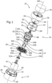
- a portable dispenser 10 comprises a dispenser body 12, a pumping assembly 14 comprising three parallel pumps 16A, 16B, 16C, a dispensing head 22 covering the pumping assembly 14, movable in rotation relative to the distributor body 12 around an axis of revolution 100 which is also a reference axis of the distributor 10, a kinematic connection 24 between the distribution head 22 and the pumping assembly 14, and an external cover 26 optional.
- the body 12 of the distributor of cylindrical external shape with a circular, oval or elliptical base centered on the reference axis 100 of the distributor, comprises a base 28, a hoop 30 attached to the base 28, a barrel 32 housed in an enclosure formed by a cylindrical outer wall 36 of the base, and a plate of support 38 pinched between the hoop 30 and the base 28.
- the plate 38 is supported against an upper annular rim of the base 28 and against an upper annular rim of the barrel 32 with the interposition of one or more seals 39, so as to delimit two separate, non-communicating volumes 40, 42 .
- the plate 38 is pierced with one or more openings 48 to bring the volume 40 to atmospheric pressure, inside the barrel 32 ( figure 4 ).
- the plate 38 is provided with three housing wells 50A, 50B, 50C, each for housing one of the pumps 16A, 16B, 16C of the pumping assembly 14.
- Each pump 16A, 16B, 16C comprises a pump body 52A, 52B, 52C snapped into the associated well 50A, 50B, 50C, an internal mechanism of known type, and a tubular nozzle 54A, 54B, 54C movable in translation relative to the pump body 52A, 52B, 52C between a rest position and a depressed position, to both activate the mechanism of the associated pump 16A, 16B, 16C and deliver through its outlet orifice a dose of the pumped fluid product.
- each nozzle 200A, 200B, 200C is parallel to the reference axis 100 of the distributor 10.
- a first pump 16A opens into the barrel 32, the other two 16B , 16C opening into the tank 42 located outside the barrel 32.
- seals can be placed in each well 50A, 50B, 50C to ensure or reinforce the seal around the pump body 52A, 52B, 52C partner.
- the barrel 32 constitutes a housing for a flexible waterproof pocket 156 into which the pump body 52A immerses.
- the 16A pump is a pump without air return.
- the ejection axes 200A, 200B, 200C are not coplanar, although other configurations are possible.
- the plate 38 is also provided with two guide tubes 58 and indexing lugs 62.
- the dispensing head 22 is made in two parts, namely an upper part 64 and a lower part 65, to which the upper part 64 is fixed by snap-fastening.
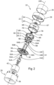
- the upper part 64 has an upper face 164 in the form of a bowl, pierced with a distribution orifice 66 centered on the reference axis 100, which opens into a well 67.
- An annular seal 102 is fixed by snap-fastening to the upper part 64 of the distribution head 22, inside the well 67.
- the distribution orifice 66 is closed by an elastomeric membrane 104 having at least one notch 106 to form a non-return valve.
- the membrane 104 is pinched between the annular seal 102 and the upper part 64 of the distribution head 22.
- the lower part 65 forms a cylindrical outer wall 68 provided at its free end with a guide flange 70, which is inserted into a reserved annular space, delimited axially by the plate 38 and by a plane annular shoulder 72 formed at the the free end of the hoop 30, the cylindrical outer wall 68 being positioned opposite a cylindrical guiding surface formed by the inner wall 130 of the hoop 30, so as to provide rotational guidance without translation of the dispensing head 22 relative to the body 12 of the distributor 10 around the reference axis 100.
- the collar 70 has two notches, each serving as a housing for an indexing tab 76.
- the lower part 65 of the dispensing head 22 has an inner face facing the plate 38, provided with a cylindrical inner skirt 78 projecting towards the plate 38 ( Figure 6 ).
- This skirt 78 has an end rim, located at a constant distance from the reference axis of the distributor, which forms an annular guide track 80 and has one or more undulations, in this case two in number, in one direction. axial parallel to the reference axis 100 of the distributor 10.
- a pusher 82 which constitutes, with the annular guide track 80, the kinematic connection making it possible to transform the rotational movement of the dispensing head 22 into a translational movement of the nozzles 54A, 54B, 54C.
- Pusher 82 illustrated in detail on the figures 9 to 12 , comprises an upper part 82.1, a lower part 82.2, and a collar 184, the three parts being fixed by gluing or any other appropriate means, for example by snap-fastening, where appropriate with the interposition of an elastomeric seal or a rod overmolded in the same material 82.3 as the upper parts 82.1 and lower parts 82.2, which allows controlled welding and perfect sealing.
- the pusher 82 is positioned inside the outer wall 68 of the dispensing head 22, and has a circular outer periphery in sliding contact with the inner face of the outer wall 68.
- the collar 184 comprises, on its upper face facing the dispensing head 22, a track 88 which has undulations located axially facing the annular guide track 80. In a reference angular position of the dispensing head 22 relative to at the pusher 82, these undulations are complementary to the undulations of the annular guide track 80.
- the flange 184 is constituted in such a way as to allow the inner skirt 78 of the distribution head 22 to come axially into sliding contact with the track 88.
- the upper part 82.1 of the pusher 82 forms a sealing sleeve 110, centered on the reference axis 100, projecting towards the distribution head and, inside this sealing sleeve 110, a tube 112 with two lumens 114A, 114B parallel to the reference axis 100.
- the two ports 114A, 114B are separated from each other by a partition 116, and each have an outlet orifice positioned opposite the membrane 104.
- the seal d The seal 102 comes into sliding elastic support against the cylindrical interior face of the sealing sleeve 110.
- a variable volume chamber 118 is thus formed directly downstream of the outlet orifices of the two ports 114A, 114B and upstream of the non-return valve formed by the membrane 104, delimited by the tube 112, the sealing sleeve 110, the seal 102 and the membrane 104.
- the pusher 82 comprises, on its lower face facing the plate 38, two guide rods 98 which are inserted into the guide tubes 58 of the plate 38 to constitute a telescopic connection for guiding in translation of the pusher 82 relative to the plate 38 parallel to the reference axis 100 of the distributor 10, as illustrated in the figure 5 .
- tubular sleeves 94A, 94B, 94C into which the nozzles 54A, 54B, 54C are inserted, preferably with a tight fit.
- a distribution conduit is provided in the pusher to connect the nozzle 54A to the outlet port of the light 114A.
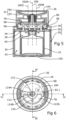
- This conduit comprises a hole 120A aligned with the nozzle 54A, passing through the wall of the lower part 82.2 of the pusher 82 and opening into an intermediate timing chamber 122A in the shape of a half-moon formed between the lower part 82.1 and the upper part 82.1 of the pusher 82.
- Light 114A of tube 112 also opens into timing chamber 122A.
- a U-shaped deflection wall 124 visible more particularly on the figures 9 to 12 , forces the fluid leaving the hole 120A to fill the timing chamber 122 before exiting through the port 114A.
- Each of the two nozzles 54B, 54C is aligned with a hole 120B, respectively 120C.
- the two holes 120B, 120C open into a common T-shaped conduit 122B formed between the lower part 82.1 and the upper part 82.1 of the pusher 82.
- the opening 114B of the tube 112 also opens into the common T-shaped conduit 122B.
- a static elastomer seal 126 ensures the sealing of the timing chamber 122A and the T-shaped conduit 122B.
- Distributor 10 operates as follows:
- the contact between the corrugated guide track 80 of the dispensing head and the corrugated guide track 88 of the pusher 82 is surface and the distance between the upper face of the pusher 82 and the plate 38 is maximum, as illustrated in the Figure 7 .
- the nozzles 54A, 54B, 54C of the pumps are at their top dead center and the springs (not shown) integrated into each of the pumps 16A, 16B, 16C push back the nozzles 54A, 54B, 54C and, through them, the pusher 82, parallel to the reference axis 100, so that the flange 70 of the dispensing head 22 bears axially against the shoulder 72 formed by the hoop 30 of the body 12 of the distributor 10. This position is therefore a position stable equilibrium.
- the indexing tabs 76 are each retained by the lugs 62, so that this position is an indexed position.
- the user After removing the cover 26, turns the dispensing head 22 relative to the body 12 of the dispenser 10 around the reference axis 100, from the indexed position of departure to the next indexed position defined by the indexing tabs 76 and the pairs of indexing lugs 62, on a half-turn, as illustrated in the figure 8 .
- the elastic snapping of the indexing tabs 76 between the lugs 62 upon arrival in the new indexed position can be perceived by the user by touch or by ear.
- the rotation of the dispensing head 22 relative to the pusher 82 imposes a relative sliding movement between the guide tracks 80 and 88. Over approximately the first half of the angular travel, therefore over a quarter of a turn, the relative movement of the tracks guide 80 and 88 generates, by a cam effect, an axial movement of the pusher 82 towards the plate 38, pushing the nozzles 54A, 54B, 54C against the force of the springs integrated into the mechanisms of the pumps 16A, 16B, 16C.
- the amplitude of this movement is such that the nozzles 54A, 54B, 54C cover at least part of their useful translation stroke, sufficient to trigger a pumping cycle.
- the pump without air intake 16A does not require priming and delivers the product contained in the deformable bag 156 from the first cycle of use.
- Air return pumps require the reservoir 42 to be pressurized during the first cycle of use.
- the descent of the pusher 82 and the nozzles 54A, 54B, 54C jointly triggers the distribution of the products contained in the deformable bag 156 and in the reservoir 42 by the pumps 16A, 16B, 16C.
- the product whose timing chamber 122A was filled in the previous cycle(s) is pushed back by the product coming from the pump 16A and travels to the outlet orifice of the light 114A.
- the product from pumps 16B and 16C travels through conduits 122B and port 114B to the outlet port of port 114B.
- the descent of the pusher 82 is accompanied by an enlargement of the volume of the chamber 118, which fills with the products ejected through the outlet orifices of the lights 114A, 114B.
- the rise of the pusher in the residual part of the rotation to the final indexed position is accompanied by a reduction in the volume of the chamber 118 and an ejection of the mixture of products contained in the chamber 118 by the anti-valve. -return 104.
- the user can then collect the dose of the two mixed products at the level of the cup 64.
- the volume VA of the timing chamber 122A and the volume VB of the common conduit 122B should be dimensioned in such a way that the difference in volume VA-VB between these two volumes is equal to the volume delivered by a 16A pump pumping cycle.
- variable volume chamber 118 it is advantageous for the maximum volume of the variable volume chamber 118 to be greater than or equal to the sum of the volumes delivered by the three pumps 16A, 16B, 16C during a pumping cycle. This ensures that the ejection of the contents of the chamber 118 by the non-return valve 104 only begins in the second part of the pumping cycle, when the pusher 82 rises.
- a pumping cycle over a half-turn is preferably independent of the direction of rotation of the distribution head 22, which can be either direct or retrograde.
- appropriate symmetries are provided for the guide tracks 80 and 88.
- nothing prevents the user to turn the dispensing head 22 always in the same direction, therefore over more than one turn, each half-turn corresponding to a pumping cycle.
- the number of pumps and tanks may vary. For example, there may be only one air return pump and one pump without air return. We can also consider three pumps immersed in three different tanks, including at least one air intake pump and one pump without air intake. We can also consider embodiments with three pumps whose axes 200A, 200B, 200C are coplanar. Providing more than one pump for a given reservoir makes it possible on the one hand to increase the dose delivered for a given translation stroke of the pusher 82, and on the other hand to balance the forces on the pusher 82.
- the useful strokes of the pumps can be identical, or different.
- the pusher it is possible, for example, for the pusher to be integral with the nozzle having the greatest useful stroke, and for the nozzles of the other pumps to be mounted sliding in the tubular sleeves 94A, 94B, 94C of the pusher.
- the fixing of the pump(s ) 16A, 16B, 16C to the body 12 of the distributor 10 can be carried out by any appropriate means.
- the general shape of the body 12 of the distributor may vary.
- the dispensing head 22 is preferably cylindrical, but other choices can be made, in particular a dispensing head having a revolution symmetry of order N around the reference axis 100, N a number integer for example equal to the number of pumping cycles obtained on one revolution of the distribution head 22.
- the deformable pocket 156 can be replaced by a piston sliding on the walls of the barrel 32 and separating a variable volume into which the pump 16A immerses from an environment outside atmospheric pressure, as illustrated for example in the application
Landscapes
- Containers And Packaging Bodies Having A Special Means To Remove Contents (AREA)
- Reciprocating Pumps (AREA)
Claims (15)
- Tragbarer Spender (10) für ein oder mehrere flüssige oder pastöse Produkte, insbesondere ein oder mehrere Kosmetik-, Körperpflege-, insbesondere Gesichtspflege-, Schmink- oder Parfümerieprodukte, umfassend:- eine Pumpanordnung (14), umfassend mindestens eine erste Pumpe (16A) und mindestens eine zweite Pumpe (16B, 16C), die erste Pumpe (16A) umfassend eine röhrenförmige Düse (54A), die zweite Pumpe (16b, 16C) umfassend eine röhrenförmige Düse (54B, 54C),- einen Drücker (82), wobei der Drücker (82) geeignet ist, um an der Düse (54A) der ersten Pumpe (16A) und an der Düse (54B, 54C) der zweiten Pumpe (16B, 16C) anzuliegen,- eine erste Spenderleitung zum Leiten einer ersten Flüssigkeit, die aus der Düse (54A) der ersten Pumpe (16A) austritt, in Richtung mindestens einer ersten Spenderöffnung (66), die eine Außenwand (164) des Spenders durchquert, und eine zweite Spenderleitung zum Leiten einer zweiten Flüssigkeit, die aus der Düse (54B, 54C) der zweiten Pumpe (16B, 16C) austritt, in Richtung mindestens einer Spenderöffnung (66), die die Außenwand des Spenders durchquert, die die erste Spenderöffnung (66) oder eine zweite Spenderöffnung sein kann;
dadurch gekennzeichnet, dass die erste Pumpe (16A) eine Pumpe ohne Luftaufnahme ist, die zweite Pumpe (16B, 16C) eine Pumpe mit Luftaufnahme ist, und die erste Spenderleitung ein größeres Volumen als die zweite Spenderleitung besitzt, wobei ein Volumenunterschied größer als das Zweifache des Volumens ist, das durch einen Pumpzyklus der Düse der ersten Pumpe abgegeben wird. - Spender nach Anspruch 1, dadurch gekennzeichnet, dass die erste Leitung eine Verzögerungszwischenkammer (122A) umfasst, die mit der Spenderöffnung durch einen Abschnitt (114A) der zweiten Leitung verbunden ist, der mindestens lokal einen Querschnitt besitzt, der kleiner als 4 mm2, vorzugsweise kleiner als 2 mm2 ist.
- Spender (10) nach einem der vorstehenden Ansprüche,
dadurch gekennzeichnet, dass der Drücker (82) mindestens einen Teil (120A, 122A, 114A) der ersten Spenderleitung zum Leiten einer ersten Flüssigkeit, die aus der ersten Düse (54A) der ersten Pumpe (16A) austritt, in Richtung der Spenderöffnung (66), und mindestens einen Teil (120B, 122B, 114B) der zweiten Spenderleitung zum Leiten einer Flüssigkeit, die aus der Düse (54B, 54C) der zweiten Pumpe (16B, 16C) austritt, in Richtung der Spenderöffnung (66) beinhaltet. - Spender nach Anspruch 3, dadurch gekennzeichnet, dass der Teil (120A, 122A, 114A) der ersten Spenderleitung, der in dem Drücker (82) beinhaltet ist, ein größeres Volumen als der Teil (120B, 122B, 114B) der zweiten Spenderleitung besitzt, der in dem Drücker (82) beinhaltet ist, wobei ein Volumenunterschied größer als oder gleich dem Volumen, das durch einen Pumpzyklus der Düse (54A) der ersten Pumpe (16A) abgegeben wird, vorzugsweise größer als das Zweifache des Volumens ist, das durch einen Pumpzyklus der Düse der ersten Pumpe abgegeben wird.
- Spender (10) nach einem der vorstehenden Ansprüche,
dadurch gekennzeichnet, dass die erste Spenderöffnung (66) mit einem Rückschlagventil (104) vorgesehen ist. - Spender (10) nach einem der vorstehenden Ansprüche,
dadurch gekennzeichnet, dass die zweite Spenderleitung geeignet ist, um die zweite Flüssigkeit, die aus der Düse (54B, 54C) der zweiten Pumpe (16B, 16C) austritt, in Richtung der ersten Spenderöffnung (66) zu leiten. - Spender (10) nach einem der vorstehenden Ansprüche, umfassend ferner einen Spenderkörper (12), in dem die Pumpanordnung (14) untergebracht ist, wobei die Düse (54A) der ersten Pumpe (16A) und die Düse (54B, 54C) der zweiten Pumpe (16B, 16C) in Bezug auf den Spenderkörper (12) parallel zu der Bezugsachse (100) translatorisch bewegbar sind, wobei der Drücker in Bezug auf den Spenderkörper (12) geführt wird.
- Spender (10) nach Anspruch 7, dadurch gekennzeichnet, dass der Drücker (82) mit dem Spenderkörper (12) durch eine Gleitverbindung (58, 98) verbunden ist, die geeignet ist, um eine translatorische Bewegung ohne Rotation des Drückers (82) in Bezug auf den Spenderkörper (12) parallel zu der Bezugsachse (100) des Spenders (10) zu führen.
- Spender (10) nach Anspruch 8, umfassend ferner einen Spenderkopf (22), der in Bezug auf den Spenderkörper (12) bewegbar ist, und eine kinematische Verbindung (24) zwischen dem Spenderkopf (22) und dem Drücker (82) zum Umwandeln einer Bewegung des Spenderkopfs (22) in Bezug auf den Spenderkörper (12) in eine translatorische Bewegung des Drückers (82) in Bezug auf den Spenderkörper (12) parallel zu der Bezugsachse (100) des Spenders.
- Spender (10) nach Anspruch 9, dadurch gekennzeichnet, dass der Spenderkopf (22) um die Bezugsachse (100) des Spenders herum rotatorisch bewegbar und in Bezug auf den Spenderkörper (12) translatorisch fest ist.
- Spender (10) nach einem der Ansprüche 9 bis 10,
dadurch gekennzeichnet, dass die Außenwand (164) des Spenders, die durch die Spenderöffnung (66) durchquert wird, eine Wand des Spenderkopfs (22) ist. - Spender (10) nach den Ansprüchen 10 und 11, in Kombination,
dadurch gekennzeichnet, dass die erste Spenderleitung und die zweite Spenderleitung eine gemeinsame Kammer (118) mit variabler Höhe umfassen, die parallel zu der Bezugsachse gemessen wird, die sich zwischen dem Drücker (82) und der ersten Spenderöffnung (66) erstreckt. - Spender (10) nach Anspruch 12, dadurch gekennzeichnet, dass die gemeinsame Kammer (118) durch zwei zylindrische Teilstücke (67, 110) begrenzt ist, die geeignet sind, um parallel zu der Bezugsachse (100) des Spenders ineinander verschoben zu werden und sich in Bezug aufeinander um die Bezugsachse (100) des Spenders herum zu drehen, wobei das eine (67) der zwei zylindrischen Teilstücke in Bezug auf den Spenderkopf (22) fest ist, während das andere (110) der zwei zylindrischen Teilstücke in Bezug auf den Drücker (82) fest ist.
- Spender (10) nach Anspruch 12, dadurch gekennzeichnet, dass die gemeinsame Kammer (118) durch eine verformbare Wand begrenzt ist, zum Beispiel eine Faltwand, die ein erstes Ende, das in Bezug auf den Spenderkopf (22) translatorisch fest ist, und ein zweites Ende aufweist, das in Bezug auf den Drücker (82) translatorisch fest ist.
- Spender nach einem der Ansprüche 11 bis 14,
dadurch gekennzeichnet, dass die gemeinsame Kammer (118) durch einen ringförmigen Dichtungsring (102) abgedichtet ist, der an einem Dichtungssitz (110) anliegt und geeignet ist, um sich in Bezug auf den Dichtungssitz (110) zu drehen, wenn sich der Spenderkopf (22) in Bezug auf den Spenderkörper (12) um die Bezugsachse (100) herum dreht.
Applications Claiming Priority (2)
| Application Number | Priority Date | Filing Date | Title |
|---|---|---|---|
| FR1907414A FR3098098B1 (fr) | 2019-07-03 | 2019-07-03 | distributeur portatif à une pompe sans reprise d’air et une pompe à reprise d’air |
| PCT/EP2020/068904 WO2021001562A1 (fr) | 2019-07-03 | 2020-07-03 | Distributeur portatif à une pompe sans reprise d'air et une pompe à reprise d'air |
Publications (2)
| Publication Number | Publication Date |
|---|---|
| EP3993910A1 EP3993910A1 (de) | 2022-05-11 |
| EP3993910B1 true EP3993910B1 (de) | 2024-03-20 |
Family
ID=68501729
Family Applications (1)
| Application Number | Title | Priority Date | Filing Date |
|---|---|---|---|
| EP20735011.7A Active EP3993910B1 (de) | 2019-07-03 | 2020-07-03 | Tragbares spendergerät mit einer airless-pumpe und einer entlüftungspumpe |
Country Status (3)
| Country | Link |
|---|---|
| EP (1) | EP3993910B1 (de) |
| FR (1) | FR3098098B1 (de) |
| WO (1) | WO2021001562A1 (de) |
Families Citing this family (1)
| Publication number | Priority date | Publication date | Assignee | Title |
|---|---|---|---|---|
| FR3148893B1 (fr) * | 2023-05-23 | 2025-10-24 | Texen | Distributeur cosmétique d’un produit fluide |
Family Cites Families (3)
| Publication number | Priority date | Publication date | Assignee | Title |
|---|---|---|---|---|
| WO2010003091A1 (en) * | 2008-07-03 | 2010-01-07 | Meadwestvaco Calmar, Inc. | Variable volume pump |
| KR101565857B1 (ko) | 2014-12-31 | 2015-11-05 | (주)연우 | 회전 토출식 염색제 용기 |
| US10919064B2 (en) * | 2018-03-16 | 2021-02-16 | Thomas Ortiz | Dispenser system |
-
2019
- 2019-07-03 FR FR1907414A patent/FR3098098B1/fr active Active
-
2020
- 2020-07-03 EP EP20735011.7A patent/EP3993910B1/de active Active
- 2020-07-03 WO PCT/EP2020/068904 patent/WO2021001562A1/fr not_active Ceased
Also Published As
| Publication number | Publication date |
|---|---|
| EP3993910A1 (de) | 2022-05-11 |
| WO2021001562A1 (fr) | 2021-01-07 |
| FR3098098A1 (fr) | 2021-01-08 |
| FR3098098B1 (fr) | 2024-01-19 |
Similar Documents
| Publication | Publication Date | Title |
|---|---|---|
| EP3762152B1 (de) | Tragbarer spender mit einer vielzahl von pumpen und rotierendem spenderkopf | |
| EP0954485B1 (de) | Vorrichtung zur abgabe vom fliessfähigen produkt mit verschlussvorrichtung | |
| EP0721573B1 (de) | Dosiergerät zur abgabe von konstanten einheitlichen dosen | |
| CA2245988C (fr) | Ensemble de conditionnement et de distribution bi-produits | |
| CA2159682C (fr) | Pompe a fluide sans volume mort | |
| CA2286377C (fr) | Embout doseur et recipient equipe d'un embout doseur selon l'invention | |
| EP0509179A1 (de) | Verfahren zum Vakuumverpacken von Produkten, insbesondere kosmetische oder pharmazeutische Produkte, in Behältern mit veränderbaren Grössen, verschlossen durch ein Verteilungsorgan ohne Abluft | |
| EP2906484B1 (de) | Dosierventil zur abgabe eines aerosols | |
| EP0466544A1 (de) | Dosierpumpe für Druckspritzen mit intrinsischer Sicherheit | |
| EP0397578B1 (de) | Vorrichtung zum Abgeben abgemessener Mengen von mindestens einem pastösen und/oder flüssigen Stoff | |
| WO1999029433A1 (fr) | Dispositif de conditionnement et distribution d'un produit, avec pompe manuelle et filtre d'entree d'air | |
| FR2705590A1 (fr) | Dispositif de distribution de liquide utilisable en position droite et ne comportant pas de tube-plongeur. | |
| FR2631564A1 (fr) | Pompe-doseuse perfectionnee pour pulverisateurs | |
| EP3993910B1 (de) | Tragbares spendergerät mit einer airless-pumpe und einer entlüftungspumpe | |
| EP1628883B1 (de) | Fluidproduktspender | |
| EP0477083B1 (de) | Vordruck-Handpumpe | |
| EP3426410B1 (de) | Fluidspender mit mitteln zur druckbeaufschlagung einer ausgabepumpe | |
| FR2634825A1 (fr) | Pompe a precompression pour la diffusion d'un liquide | |
| EP1103490B1 (de) | Zerstäuber mit Treibgas | |
| EP2906483A1 (de) | Dosierventil zur abgabe eines aerosols | |
| WO2025012558A1 (fr) | Dispositif de distribution de produit fluide | |
| WO2023208890A1 (fr) | Dispositif de distribution d'un produit fluide | |
| FR2719084A1 (fr) | Dispositif de réglage du volume d'une chambre de pompe d'une pompe à précompression. | |
| FR2757786A1 (fr) | Ensemble de conditionnement de liquide, notamment d'un produit cosmetique ou d'un medicament |
Legal Events
| Date | Code | Title | Description |
|---|---|---|---|
| STAA | Information on the status of an ep patent application or granted ep patent |
Free format text: STATUS: UNKNOWN |
|
| STAA | Information on the status of an ep patent application or granted ep patent |
Free format text: STATUS: THE INTERNATIONAL PUBLICATION HAS BEEN MADE |
|
| PUAI | Public reference made under article 153(3) epc to a published international application that has entered the european phase |
Free format text: ORIGINAL CODE: 0009012 |
|
| STAA | Information on the status of an ep patent application or granted ep patent |
Free format text: STATUS: REQUEST FOR EXAMINATION WAS MADE |
|
| 17P | Request for examination filed |
Effective date: 20211223 |
|
| AK | Designated contracting states |
Kind code of ref document: A1 Designated state(s): AL AT BE BG CH CY CZ DE DK EE ES FI FR GB GR HR HU IE IS IT LI LT LU LV MC MK MT NL NO PL PT RO RS SE SI SK SM TR |
|
| DAV | Request for validation of the european patent (deleted) | ||
| DAX | Request for extension of the european patent (deleted) | ||
| GRAP | Despatch of communication of intention to grant a patent |
Free format text: ORIGINAL CODE: EPIDOSNIGR1 |
|
| STAA | Information on the status of an ep patent application or granted ep patent |
Free format text: STATUS: GRANT OF PATENT IS INTENDED |
|
| INTG | Intention to grant announced |
Effective date: 20231013 |
|
| GRAS | Grant fee paid |
Free format text: ORIGINAL CODE: EPIDOSNIGR3 |
|
| GRAA | (expected) grant |
Free format text: ORIGINAL CODE: 0009210 |
|
| STAA | Information on the status of an ep patent application or granted ep patent |
Free format text: STATUS: THE PATENT HAS BEEN GRANTED |
|
| AK | Designated contracting states |
Kind code of ref document: B1 Designated state(s): AL AT BE BG CH CY CZ DE DK EE ES FI FR GB GR HR HU IE IS IT LI LT LU LV MC MK MT NL NO PL PT RO RS SE SI SK SM TR |
|
| REG | Reference to a national code |
Ref country code: GB Ref legal event code: FG4D Free format text: NOT ENGLISH |
|
| REG | Reference to a national code |
Ref country code: CH Ref legal event code: EP |
|
| REG | Reference to a national code |
Ref country code: IE Ref legal event code: FG4D Free format text: LANGUAGE OF EP DOCUMENT: FRENCH |
|
| REG | Reference to a national code |
Ref country code: DE Ref legal event code: R096 Ref document number: 602020027526 Country of ref document: DE |
|
| PG25 | Lapsed in a contracting state [announced via postgrant information from national office to epo] |
Ref country code: LT Free format text: LAPSE BECAUSE OF FAILURE TO SUBMIT A TRANSLATION OF THE DESCRIPTION OR TO PAY THE FEE WITHIN THE PRESCRIBED TIME-LIMIT Effective date: 20240320 |
|
| REG | Reference to a national code |
Ref country code: LT Ref legal event code: MG9D |
|
| PG25 | Lapsed in a contracting state [announced via postgrant information from national office to epo] |
Ref country code: GR Free format text: LAPSE BECAUSE OF FAILURE TO SUBMIT A TRANSLATION OF THE DESCRIPTION OR TO PAY THE FEE WITHIN THE PRESCRIBED TIME-LIMIT Effective date: 20240621 |
|
| PG25 | Lapsed in a contracting state [announced via postgrant information from national office to epo] |
Ref country code: RS Free format text: LAPSE BECAUSE OF FAILURE TO SUBMIT A TRANSLATION OF THE DESCRIPTION OR TO PAY THE FEE WITHIN THE PRESCRIBED TIME-LIMIT Effective date: 20240620 Ref country code: HR Free format text: LAPSE BECAUSE OF FAILURE TO SUBMIT A TRANSLATION OF THE DESCRIPTION OR TO PAY THE FEE WITHIN THE PRESCRIBED TIME-LIMIT Effective date: 20240320 |
|
| REG | Reference to a national code |
Ref country code: NL Ref legal event code: MP Effective date: 20240320 |
|
| PG25 | Lapsed in a contracting state [announced via postgrant information from national office to epo] |
Ref country code: RS Free format text: LAPSE BECAUSE OF FAILURE TO SUBMIT A TRANSLATION OF THE DESCRIPTION OR TO PAY THE FEE WITHIN THE PRESCRIBED TIME-LIMIT Effective date: 20240620 Ref country code: NO Free format text: LAPSE BECAUSE OF FAILURE TO SUBMIT A TRANSLATION OF THE DESCRIPTION OR TO PAY THE FEE WITHIN THE PRESCRIBED TIME-LIMIT Effective date: 20240620 Ref country code: LT Free format text: LAPSE BECAUSE OF FAILURE TO SUBMIT A TRANSLATION OF THE DESCRIPTION OR TO PAY THE FEE WITHIN THE PRESCRIBED TIME-LIMIT Effective date: 20240320 Ref country code: HR Free format text: LAPSE BECAUSE OF FAILURE TO SUBMIT A TRANSLATION OF THE DESCRIPTION OR TO PAY THE FEE WITHIN THE PRESCRIBED TIME-LIMIT Effective date: 20240320 Ref country code: GR Free format text: LAPSE BECAUSE OF FAILURE TO SUBMIT A TRANSLATION OF THE DESCRIPTION OR TO PAY THE FEE WITHIN THE PRESCRIBED TIME-LIMIT Effective date: 20240621 Ref country code: FI Free format text: LAPSE BECAUSE OF FAILURE TO SUBMIT A TRANSLATION OF THE DESCRIPTION OR TO PAY THE FEE WITHIN THE PRESCRIBED TIME-LIMIT Effective date: 20240320 Ref country code: BG Free format text: LAPSE BECAUSE OF FAILURE TO SUBMIT A TRANSLATION OF THE DESCRIPTION OR TO PAY THE FEE WITHIN THE PRESCRIBED TIME-LIMIT Effective date: 20240320 |
|
| REG | Reference to a national code |
Ref country code: AT Ref legal event code: MK05 Ref document number: 1667380 Country of ref document: AT Kind code of ref document: T Effective date: 20240320 |
|
| PG25 | Lapsed in a contracting state [announced via postgrant information from national office to epo] |
Ref country code: SE Free format text: LAPSE BECAUSE OF FAILURE TO SUBMIT A TRANSLATION OF THE DESCRIPTION OR TO PAY THE FEE WITHIN THE PRESCRIBED TIME-LIMIT Effective date: 20240320 Ref country code: LV Free format text: LAPSE BECAUSE OF FAILURE TO SUBMIT A TRANSLATION OF THE DESCRIPTION OR TO PAY THE FEE WITHIN THE PRESCRIBED TIME-LIMIT Effective date: 20240320 |
|
| PG25 | Lapsed in a contracting state [announced via postgrant information from national office to epo] |
Ref country code: NL Free format text: LAPSE BECAUSE OF FAILURE TO SUBMIT A TRANSLATION OF THE DESCRIPTION OR TO PAY THE FEE WITHIN THE PRESCRIBED TIME-LIMIT Effective date: 20240320 |
|
| PG25 | Lapsed in a contracting state [announced via postgrant information from national office to epo] |
Ref country code: NL Free format text: LAPSE BECAUSE OF FAILURE TO SUBMIT A TRANSLATION OF THE DESCRIPTION OR TO PAY THE FEE WITHIN THE PRESCRIBED TIME-LIMIT Effective date: 20240320 |
|
| PG25 | Lapsed in a contracting state [announced via postgrant information from national office to epo] |
Ref country code: IS Free format text: LAPSE BECAUSE OF FAILURE TO SUBMIT A TRANSLATION OF THE DESCRIPTION OR TO PAY THE FEE WITHIN THE PRESCRIBED TIME-LIMIT Effective date: 20240720 |
|
| PG25 | Lapsed in a contracting state [announced via postgrant information from national office to epo] |
Ref country code: PT Free format text: LAPSE BECAUSE OF FAILURE TO SUBMIT A TRANSLATION OF THE DESCRIPTION OR TO PAY THE FEE WITHIN THE PRESCRIBED TIME-LIMIT Effective date: 20240722 Ref country code: SM Free format text: LAPSE BECAUSE OF FAILURE TO SUBMIT A TRANSLATION OF THE DESCRIPTION OR TO PAY THE FEE WITHIN THE PRESCRIBED TIME-LIMIT Effective date: 20240320 |
|
| PG25 | Lapsed in a contracting state [announced via postgrant information from national office to epo] |
Ref country code: ES Free format text: LAPSE BECAUSE OF FAILURE TO SUBMIT A TRANSLATION OF THE DESCRIPTION OR TO PAY THE FEE WITHIN THE PRESCRIBED TIME-LIMIT Effective date: 20240320 |
|
| PG25 | Lapsed in a contracting state [announced via postgrant information from national office to epo] |
Ref country code: CZ Free format text: LAPSE BECAUSE OF FAILURE TO SUBMIT A TRANSLATION OF THE DESCRIPTION OR TO PAY THE FEE WITHIN THE PRESCRIBED TIME-LIMIT Effective date: 20240320 Ref country code: EE Free format text: LAPSE BECAUSE OF FAILURE TO SUBMIT A TRANSLATION OF THE DESCRIPTION OR TO PAY THE FEE WITHIN THE PRESCRIBED TIME-LIMIT Effective date: 20240320 |
|
| PG25 | Lapsed in a contracting state [announced via postgrant information from national office to epo] |
Ref country code: AT Free format text: LAPSE BECAUSE OF FAILURE TO SUBMIT A TRANSLATION OF THE DESCRIPTION OR TO PAY THE FEE WITHIN THE PRESCRIBED TIME-LIMIT Effective date: 20240320 |
|
| PG25 | Lapsed in a contracting state [announced via postgrant information from national office to epo] |
Ref country code: PL Free format text: LAPSE BECAUSE OF FAILURE TO SUBMIT A TRANSLATION OF THE DESCRIPTION OR TO PAY THE FEE WITHIN THE PRESCRIBED TIME-LIMIT Effective date: 20240320 |
|
| PG25 | Lapsed in a contracting state [announced via postgrant information from national office to epo] |
Ref country code: SK Free format text: LAPSE BECAUSE OF FAILURE TO SUBMIT A TRANSLATION OF THE DESCRIPTION OR TO PAY THE FEE WITHIN THE PRESCRIBED TIME-LIMIT Effective date: 20240320 |
|
| PG25 | Lapsed in a contracting state [announced via postgrant information from national office to epo] |
Ref country code: SM Free format text: LAPSE BECAUSE OF FAILURE TO SUBMIT A TRANSLATION OF THE DESCRIPTION OR TO PAY THE FEE WITHIN THE PRESCRIBED TIME-LIMIT Effective date: 20240320 Ref country code: SK Free format text: LAPSE BECAUSE OF FAILURE TO SUBMIT A TRANSLATION OF THE DESCRIPTION OR TO PAY THE FEE WITHIN THE PRESCRIBED TIME-LIMIT Effective date: 20240320 Ref country code: RO Free format text: LAPSE BECAUSE OF FAILURE TO SUBMIT A TRANSLATION OF THE DESCRIPTION OR TO PAY THE FEE WITHIN THE PRESCRIBED TIME-LIMIT Effective date: 20240320 Ref country code: PT Free format text: LAPSE BECAUSE OF FAILURE TO SUBMIT A TRANSLATION OF THE DESCRIPTION OR TO PAY THE FEE WITHIN THE PRESCRIBED TIME-LIMIT Effective date: 20240722 Ref country code: PL Free format text: LAPSE BECAUSE OF FAILURE TO SUBMIT A TRANSLATION OF THE DESCRIPTION OR TO PAY THE FEE WITHIN THE PRESCRIBED TIME-LIMIT Effective date: 20240320 Ref country code: IS Free format text: LAPSE BECAUSE OF FAILURE TO SUBMIT A TRANSLATION OF THE DESCRIPTION OR TO PAY THE FEE WITHIN THE PRESCRIBED TIME-LIMIT Effective date: 20240720 Ref country code: ES Free format text: LAPSE BECAUSE OF FAILURE TO SUBMIT A TRANSLATION OF THE DESCRIPTION OR TO PAY THE FEE WITHIN THE PRESCRIBED TIME-LIMIT Effective date: 20240320 Ref country code: EE Free format text: LAPSE BECAUSE OF FAILURE TO SUBMIT A TRANSLATION OF THE DESCRIPTION OR TO PAY THE FEE WITHIN THE PRESCRIBED TIME-LIMIT Effective date: 20240320 Ref country code: CZ Free format text: LAPSE BECAUSE OF FAILURE TO SUBMIT A TRANSLATION OF THE DESCRIPTION OR TO PAY THE FEE WITHIN THE PRESCRIBED TIME-LIMIT Effective date: 20240320 Ref country code: AT Free format text: LAPSE BECAUSE OF FAILURE TO SUBMIT A TRANSLATION OF THE DESCRIPTION OR TO PAY THE FEE WITHIN THE PRESCRIBED TIME-LIMIT Effective date: 20240320 |
|
| PG25 | Lapsed in a contracting state [announced via postgrant information from national office to epo] |
Ref country code: IT Free format text: LAPSE BECAUSE OF FAILURE TO SUBMIT A TRANSLATION OF THE DESCRIPTION OR TO PAY THE FEE WITHIN THE PRESCRIBED TIME-LIMIT Effective date: 20240320 |
|
| REG | Reference to a national code |
Ref country code: DE Ref legal event code: R097 Ref document number: 602020027526 Country of ref document: DE |
|
| PG25 | Lapsed in a contracting state [announced via postgrant information from national office to epo] |
Ref country code: IT Free format text: LAPSE BECAUSE OF FAILURE TO SUBMIT A TRANSLATION OF THE DESCRIPTION OR TO PAY THE FEE WITHIN THE PRESCRIBED TIME-LIMIT Effective date: 20240320 |
|
| PG25 | Lapsed in a contracting state [announced via postgrant information from national office to epo] |
Ref country code: DK Free format text: LAPSE BECAUSE OF FAILURE TO SUBMIT A TRANSLATION OF THE DESCRIPTION OR TO PAY THE FEE WITHIN THE PRESCRIBED TIME-LIMIT Effective date: 20240320 |
|
| PLBE | No opposition filed within time limit |
Free format text: ORIGINAL CODE: 0009261 |
|
| STAA | Information on the status of an ep patent application or granted ep patent |
Free format text: STATUS: NO OPPOSITION FILED WITHIN TIME LIMIT |
|
| PG25 | Lapsed in a contracting state [announced via postgrant information from national office to epo] |
Ref country code: DK Free format text: LAPSE BECAUSE OF FAILURE TO SUBMIT A TRANSLATION OF THE DESCRIPTION OR TO PAY THE FEE WITHIN THE PRESCRIBED TIME-LIMIT Effective date: 20240320 |
|
| PG25 | Lapsed in a contracting state [announced via postgrant information from national office to epo] |
Ref country code: MC Free format text: LAPSE BECAUSE OF FAILURE TO SUBMIT A TRANSLATION OF THE DESCRIPTION OR TO PAY THE FEE WITHIN THE PRESCRIBED TIME-LIMIT Effective date: 20240320 |
|
| 26N | No opposition filed |
Effective date: 20241223 |
|
| REG | Reference to a national code |
Ref country code: CH Ref legal event code: PL |
|
| PG25 | Lapsed in a contracting state [announced via postgrant information from national office to epo] |
Ref country code: LU Free format text: LAPSE BECAUSE OF NON-PAYMENT OF DUE FEES Effective date: 20240703 |
|
| GBPC | Gb: european patent ceased through non-payment of renewal fee |
Effective date: 20240703 |
|
| PG25 | Lapsed in a contracting state [announced via postgrant information from national office to epo] |
Ref country code: LU Free format text: LAPSE BECAUSE OF NON-PAYMENT OF DUE FEES Effective date: 20240703 |
|
| PG25 | Lapsed in a contracting state [announced via postgrant information from national office to epo] |
Ref country code: SI Free format text: LAPSE BECAUSE OF FAILURE TO SUBMIT A TRANSLATION OF THE DESCRIPTION OR TO PAY THE FEE WITHIN THE PRESCRIBED TIME-LIMIT Effective date: 20240320 Ref country code: BE Free format text: LAPSE BECAUSE OF NON-PAYMENT OF DUE FEES Effective date: 20240731 Ref country code: CH Free format text: LAPSE BECAUSE OF NON-PAYMENT OF DUE FEES Effective date: 20240731 |
|
| PGFP | Annual fee paid to national office [announced via postgrant information from national office to epo] |
Ref country code: FR Payment date: 20250325 Year of fee payment: 6 |
|
| PG25 | Lapsed in a contracting state [announced via postgrant information from national office to epo] |
Ref country code: GB Free format text: LAPSE BECAUSE OF NON-PAYMENT OF DUE FEES Effective date: 20240703 |
|
| REG | Reference to a national code |
Ref country code: BE Ref legal event code: MM Effective date: 20240731 |
|
| PG25 | Lapsed in a contracting state [announced via postgrant information from national office to epo] |
Ref country code: IE Free format text: LAPSE BECAUSE OF NON-PAYMENT OF DUE FEES Effective date: 20240703 |
|
| PGFP | Annual fee paid to national office [announced via postgrant information from national office to epo] |
Ref country code: DE Payment date: 20250722 Year of fee payment: 6 |
|
| PG25 | Lapsed in a contracting state [announced via postgrant information from national office to epo] |
Ref country code: CY Free format text: LAPSE BECAUSE OF FAILURE TO SUBMIT A TRANSLATION OF THE DESCRIPTION OR TO PAY THE FEE WITHIN THE PRESCRIBED TIME-LIMIT; INVALID AB INITIO Effective date: 20200703 |
|
| PG25 | Lapsed in a contracting state [announced via postgrant information from national office to epo] |
Ref country code: HU Free format text: LAPSE BECAUSE OF FAILURE TO SUBMIT A TRANSLATION OF THE DESCRIPTION OR TO PAY THE FEE WITHIN THE PRESCRIBED TIME-LIMIT; INVALID AB INITIO Effective date: 20200703 |