EP3218602B1 - Manuelle pumpe - Google Patents
Manuelle pumpe Download PDFInfo
- Publication number
- EP3218602B1 EP3218602B1 EP15817440.9A EP15817440A EP3218602B1 EP 3218602 B1 EP3218602 B1 EP 3218602B1 EP 15817440 A EP15817440 A EP 15817440A EP 3218602 B1 EP3218602 B1 EP 3218602B1
- Authority
- EP
- European Patent Office
- Prior art keywords
- pump
- return passage
- fluid
- manual
- pump chamber
- Prior art date
- Legal status (The legal status is an assumption and is not a legal conclusion. Google has not performed a legal analysis and makes no representation as to the accuracy of the status listed.)
- Active
Links
- 239000012530 fluid Substances 0.000 claims description 66
- 238000007789 sealing Methods 0.000 claims description 6
- 230000007547 defect Effects 0.000 description 4
- 239000008188 pellet Substances 0.000 description 3
- 239000002537 cosmetic Substances 0.000 description 2
- 230000000284 resting effect Effects 0.000 description 2
- 239000011324 bead Substances 0.000 description 1
- 239000006071 cream Substances 0.000 description 1
- 230000001186 cumulative effect Effects 0.000 description 1
- 230000000994 depressogenic effect Effects 0.000 description 1
- 238000006073 displacement reaction Methods 0.000 description 1
- 230000005484 gravity Effects 0.000 description 1
- 239000006210 lotion Substances 0.000 description 1
- 239000000463 material Substances 0.000 description 1
- 239000002304 perfume Substances 0.000 description 1
- 230000002093 peripheral effect Effects 0.000 description 1
- 239000000825 pharmaceutical preparation Substances 0.000 description 1
- 229940127557 pharmaceutical product Drugs 0.000 description 1
- 238000011144 upstream manufacturing Methods 0.000 description 1
- XLYOFNOQVPJJNP-UHFFFAOYSA-N water Substances O XLYOFNOQVPJJNP-UHFFFAOYSA-N 0.000 description 1
Images


Classifications
-
- F—MECHANICAL ENGINEERING; LIGHTING; HEATING; WEAPONS; BLASTING
- F04—POSITIVE - DISPLACEMENT MACHINES FOR LIQUIDS; PUMPS FOR LIQUIDS OR ELASTIC FLUIDS
- F04B—POSITIVE-DISPLACEMENT MACHINES FOR LIQUIDS; PUMPS
- F04B49/00—Control, e.g. of pump delivery, or pump pressure of, or safety measures for, machines, pumps, or pumping installations, not otherwise provided for, or of interest apart from, groups F04B1/00 - F04B47/00
- F04B49/22—Control, e.g. of pump delivery, or pump pressure of, or safety measures for, machines, pumps, or pumping installations, not otherwise provided for, or of interest apart from, groups F04B1/00 - F04B47/00 by means of valves
- F04B49/24—Bypassing
-
- B—PERFORMING OPERATIONS; TRANSPORTING
- B05—SPRAYING OR ATOMISING IN GENERAL; APPLYING FLUENT MATERIALS TO SURFACES, IN GENERAL
- B05B—SPRAYING APPARATUS; ATOMISING APPARATUS; NOZZLES
- B05B11/00—Single-unit hand-held apparatus in which flow of contents is produced by the muscular force of the operator at the moment of use
- B05B11/01—Single-unit hand-held apparatus in which flow of contents is produced by the muscular force of the operator at the moment of use characterised by the means producing the flow
- B05B11/10—Pump arrangements for transferring the contents from the container to a pump chamber by a sucking effect and forcing the contents out through the dispensing nozzle
- B05B11/1001—Piston pumps
- B05B11/1023—Piston pumps having an outlet valve opened by deformation or displacement of the piston relative to its actuating stem
- B05B11/1025—Piston pumps having an outlet valve opened by deformation or displacement of the piston relative to its actuating stem a spring urging the outlet valve in its closed position
-
- B—PERFORMING OPERATIONS; TRANSPORTING
- B05—SPRAYING OR ATOMISING IN GENERAL; APPLYING FLUENT MATERIALS TO SURFACES, IN GENERAL
- B05B—SPRAYING APPARATUS; ATOMISING APPARATUS; NOZZLES
- B05B11/00—Single-unit hand-held apparatus in which flow of contents is produced by the muscular force of the operator at the moment of use
- B05B11/01—Single-unit hand-held apparatus in which flow of contents is produced by the muscular force of the operator at the moment of use characterised by the means producing the flow
- B05B11/10—Pump arrangements for transferring the contents from the container to a pump chamber by a sucking effect and forcing the contents out through the dispensing nozzle
- B05B11/1042—Components or details
- B05B11/1043—Sealing or attachment arrangements between pump and container
- B05B11/1046—Sealing or attachment arrangements between pump and container the pump chamber being arranged substantially coaxially to the neck of the container
-
- B—PERFORMING OPERATIONS; TRANSPORTING
- B05—SPRAYING OR ATOMISING IN GENERAL; APPLYING FLUENT MATERIALS TO SURFACES, IN GENERAL
- B05B—SPRAYING APPARATUS; ATOMISING APPARATUS; NOZZLES
- B05B11/00—Single-unit hand-held apparatus in which flow of contents is produced by the muscular force of the operator at the moment of use
- B05B11/01—Single-unit hand-held apparatus in which flow of contents is produced by the muscular force of the operator at the moment of use characterised by the means producing the flow
- B05B11/10—Pump arrangements for transferring the contents from the container to a pump chamber by a sucking effect and forcing the contents out through the dispensing nozzle
- B05B11/1042—Components or details
- B05B11/105—Sealing arrangements around pump actuating stem
-
- B—PERFORMING OPERATIONS; TRANSPORTING
- B05—SPRAYING OR ATOMISING IN GENERAL; APPLYING FLUENT MATERIALS TO SURFACES, IN GENERAL
- B05B—SPRAYING APPARATUS; ATOMISING APPARATUS; NOZZLES
- B05B11/00—Single-unit hand-held apparatus in which flow of contents is produced by the muscular force of the operator at the moment of use
- B05B11/01—Single-unit hand-held apparatus in which flow of contents is produced by the muscular force of the operator at the moment of use characterised by the means producing the flow
- B05B11/10—Pump arrangements for transferring the contents from the container to a pump chamber by a sucking effect and forcing the contents out through the dispensing nozzle
- B05B11/1042—Components or details
- B05B11/1066—Pump inlet valves
- B05B11/1067—Pump inlet valves actuated by pressure
-
- F—MECHANICAL ENGINEERING; LIGHTING; HEATING; WEAPONS; BLASTING
- F04—POSITIVE - DISPLACEMENT MACHINES FOR LIQUIDS; PUMPS FOR LIQUIDS OR ELASTIC FLUIDS
- F04B—POSITIVE-DISPLACEMENT MACHINES FOR LIQUIDS; PUMPS
- F04B23/00—Pumping installations or systems
- F04B23/02—Pumping installations or systems having reservoirs
- F04B23/025—Pumping installations or systems having reservoirs the pump being located directly adjacent the reservoir
- F04B23/028—Pumping installations or systems having reservoirs the pump being located directly adjacent the reservoir the pump being mounted on top of the reservoir
-
- F—MECHANICAL ENGINEERING; LIGHTING; HEATING; WEAPONS; BLASTING
- F04—POSITIVE - DISPLACEMENT MACHINES FOR LIQUIDS; PUMPS FOR LIQUIDS OR ELASTIC FLUIDS
- F04B—POSITIVE-DISPLACEMENT MACHINES FOR LIQUIDS; PUMPS
- F04B49/00—Control, e.g. of pump delivery, or pump pressure of, or safety measures for, machines, pumps, or pumping installations, not otherwise provided for, or of interest apart from, groups F04B1/00 - F04B47/00
- F04B49/02—Stopping, starting, unloading or idling control
- F04B49/03—Stopping, starting, unloading or idling control by means of valves
- F04B49/035—Bypassing
-
- F—MECHANICAL ENGINEERING; LIGHTING; HEATING; WEAPONS; BLASTING
- F04—POSITIVE - DISPLACEMENT MACHINES FOR LIQUIDS; PUMPS FOR LIQUIDS OR ELASTIC FLUIDS
- F04B—POSITIVE-DISPLACEMENT MACHINES FOR LIQUIDS; PUMPS
- F04B9/00—Piston machines or pumps characterised by the driving or driven means to or from their working members
- F04B9/14—Pumps characterised by muscle-power operation
-
- B—PERFORMING OPERATIONS; TRANSPORTING
- B05—SPRAYING OR ATOMISING IN GENERAL; APPLYING FLUENT MATERIALS TO SURFACES, IN GENERAL
- B05B—SPRAYING APPARATUS; ATOMISING APPARATUS; NOZZLES
- B05B11/00—Single-unit hand-held apparatus in which flow of contents is produced by the muscular force of the operator at the moment of use
- B05B11/01—Single-unit hand-held apparatus in which flow of contents is produced by the muscular force of the operator at the moment of use characterised by the means producing the flow
- B05B11/10—Pump arrangements for transferring the contents from the container to a pump chamber by a sucking effect and forcing the contents out through the dispensing nozzle
- B05B11/1042—Components or details
- B05B11/1043—Sealing or attachment arrangements between pump and container
- B05B11/1049—Attachment arrangements comprising a deformable or resilient ferrule clamped or locked onto the neck of the container by displacing, e.g. sliding, a sleeve surrounding the ferrule
-
- F—MECHANICAL ENGINEERING; LIGHTING; HEATING; WEAPONS; BLASTING
- F04—POSITIVE - DISPLACEMENT MACHINES FOR LIQUIDS; PUMPS FOR LIQUIDS OR ELASTIC FLUIDS
- F04B—POSITIVE-DISPLACEMENT MACHINES FOR LIQUIDS; PUMPS
- F04B53/00—Component parts, details or accessories not provided for in, or of interest apart from, groups F04B1/00 - F04B23/00 or F04B39/00 - F04B47/00
- F04B53/10—Valves; Arrangement of valves
- F04B53/1087—Valve seats
-
- F—MECHANICAL ENGINEERING; LIGHTING; HEATING; WEAPONS; BLASTING
- F04—POSITIVE - DISPLACEMENT MACHINES FOR LIQUIDS; PUMPS FOR LIQUIDS OR ELASTIC FLUIDS
- F04B—POSITIVE-DISPLACEMENT MACHINES FOR LIQUIDS; PUMPS
- F04B53/00—Component parts, details or accessories not provided for in, or of interest apart from, groups F04B1/00 - F04B23/00 or F04B39/00 - F04B47/00
- F04B53/14—Pistons, piston-rods or piston-rod connections
-
- F—MECHANICAL ENGINEERING; LIGHTING; HEATING; WEAPONS; BLASTING
- F04—POSITIVE - DISPLACEMENT MACHINES FOR LIQUIDS; PUMPS FOR LIQUIDS OR ELASTIC FLUIDS
- F04B—POSITIVE-DISPLACEMENT MACHINES FOR LIQUIDS; PUMPS
- F04B53/00—Component parts, details or accessories not provided for in, or of interest apart from, groups F04B1/00 - F04B23/00 or F04B39/00 - F04B47/00
- F04B53/16—Casings; Cylinders; Cylinder liners or heads; Fluid connections
Definitions
- the present invention relates to a manual pump for dispensing a fluid product, this pump being intended to be associated with a fluid reservoir to thereby form a fluid dispenser.
- the pump comprises a pump body defining a sliding shaft for a piston integral with an actuating rod, the pump comprising a pump chamber in which a dose of fluid is pressurized at each actuation.
- the pump also includes an outlet valve disposed between the pump chamber and a dispensing orifice to discharge fluid from the pump chamber, the pump comprising an inlet valve disposed between the pump chamber and an inlet of the pump chamber. pump for introducing fluid into the pump chamber from the reservoir, the inlet valve comprising a movable member which selectively rests on a valve seat. This is a quite conventional and conventional design for a pump in the field of perfumery, cosmetics or pharmacy.
- the volume of the pump chamber is determined and frozen for a particular pump model. In other words, it is generally not possible to change the volume of the pump chamber. It is however possible to adjust the volume of the pump chamber by acting on the top dead center corresponding to the rest position of the actuating rod and piston, as proposed for example in the document FR2719084 . It is intended in this document to drive more or less the collar in the pump body to adjust the volume of the pump chamber. One then acts on the stroke height of the piston. Therefore, the pusher mounted on the pump is movable to a reduced height, which may hinder the user who feels unable to push the button fully.
- the present invention aims to overcome the aforementioned drawbacks of the prior art by defining a manual pump of standard capacity but which is capable of delivering a dose of fluid that is less than the volume of the pump chamber, without reducing the stroke piston and actuator rod and without reducing the volume of the pump chamber.
- an object of the present invention is to dispense a partial dose of fluid product with respect to the capacity of the pump chamber.
- the present invention proposes that the pump is provided with a return passage allowing a portion of the fluid product pressurized in the pump chamber to escape without passing through the outlet valve.
- the entire fluid dose stored in the pump chamber is not discharged through the outlet valve towards the dispensing orifice: a portion being diverted through the return passage, so that the fluid dispensed only corresponds to a partial dose of the pump.
- the return passage communicates directly or indirectly with the fluid reservoir, so that the fluid that passes through the return passage is reinjected into the fluid reservoir.
- the fluid product passing through the return passage is stored, at least for a moment, in a buffer tank which may or may not communicate with the fluid reservoir.
- the return passage creates a sealing defect at the inlet valve.
- the inlet flap is leaking.
- the return passage may be formed by the movable member.
- the return passage comprises at least one groove formed at the level where the movable member comes into contact with its valve seat.
- the return passage comprises a hole which passes through the movable member which is advantageously in the form of a disc. It is also possible to provide that the return passage is formed by the valve seat, in particular in the form of at least one groove.
- the return passage can be formed by the movable member and / or its valve seat.
- an additional return passage may be formed by the pump body.
- the additional return passage comprises a direct bore which passes through the wall thickness of the pump body and directly connects the pump chamber to the reservoir.
- the pump body comprises a plunger tube connected to the inlet of the pump, the additional return passage comprising a bypass path which connects the pump chamber to the plunger tube without passing through the flap valve. Entrance.
- the bypass path makes it possible to bypass the inlet valve.
- the pump comprises an outer sleeve which surrounds the pump body, the bypass path extending in part between the pump body and the outer sleeve and advantageously comprising at least one internal bore which passes through the wall thickness of the pump body. pump body.
- the additional return passage can be formed in the sliding shaft.
- the invention also defines a fluid dispenser comprising a fluid reservoir on which is mounted a manual pump as defined above, the return passage, and optionally the additional return passage, allowing a portion of the fluid product. pressurized in the pump chamber to be returned directly or indirectly to the fluid reservoir.
- the spirit of the invention lies in providing a kind of leakage at the pump chamber, so that the entire dose stored in the pump chamber is not discharged through the outlet valve and the dispensing orifice, a greater or lesser portion of this dose being redirected to another outlet which preferably communicates with the fluid reservoir.
- the leak can be achieved at the inlet valve, and directly at the wall of the pump chamber which communicates directly with the fluid reservoir, and again so as to shunt the inlet valve by connecting the chamber pump directly to the dip tube.
- additional return passages can be implemented independently of the return passages at the inlet valve in certain embodiments. Separate protection could be sought for these additional return passages.
- the fluid dispenser comprises a fluid reservoir R for containing a fluid product, which may for example be a perfume, a toilet water, a lotion, a cream, a gel, a pharmaceutical product, etc.
- a fluid product which may for example be a perfume, a toilet water, a lotion, a cream, a gel, a pharmaceutical product, etc.
- the fluid reservoir R may be made of any suitable material and have any configuration, since the reservoir itself is not critical to the present invention.
- the tank R may for example be provided with an N-neck which defines a narrowed opening in which is housed the manual pump P.
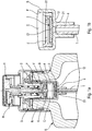
- the pump P comprises in a quite conventional manner a pump body B defining a fluid product inlet I which can be provided with a dip tube T which extends into the reservoir R to near or in contact with its bottom. .
- the body B also defines a sliding shaft F which has a cylindrical shape, preferably circular.
- Body B is also provided upstream of its input I of an inlet valve which comprises a movable member 2 for selectively coming into sealing contact with a valve seat 12. This inlet valve will be described in greater detail below.
- the pump P also comprises an actuating rod S which is capped with a pusher H defining a dispensing orifice O.
- the actuating rod S serves as a support for a piston K and an outlet valve V.
- the piston K The pump P thus defines a pump chamber C intended to be filled with fluid from the tank R through the dip tube T and the inlet flap.
- the user can press the pusher H to push the actuating rod S inside the pump body D.
- the piston K is slidably mounted on the actuating rod S against a precompression spring, so that the outlet valve V will open as soon as the pressure inside the pump chamber C has reached a predetermined threshold. Specifically, the piston K resting against the outlet valve V sealingly.
- the inlet valve comprises a movable member 2 which is in the form of a disk, a pellet or a washer which rests in a sealed manner on a valve seat 12.
- the disc has an annular shape with a lower face 21 and an upper face 22 which extend substantially parallel.
- the peripheral portion of the movable member 2 may for example be circular cylindrical.
- the lower face 21 is in contact with the valve seat 12, which may for example be in the form of a bead or an annular rib.
- a stroke limiter J which is fixed inside the pump body B. The stroke limiter J, however, allows the passage of fluid product.
- the movable member 2 is formed with a through hole 23 which connects the lower face 21 to the upper face 22.
- the through hole 23 has a reduced passage section with respect to the diameter of the sliding shaft F, and even to the internal diameter of the dip tube T.
- the passage section of the through hole 23 may be of the order of 0.1 mm 2 .
- the figure 1b represents only one through hole 23, but it can provide several through holes, without departing from the scope of the invention.
- the outlet valve V will open to let a portion of the fluid product from the pump chamber, but another part of the fluid product of the pump chamber will be returned to the dip tube T through the through hole 23 of the movable member 2.
- This through hole 23 forms a return passage which allows a portion of the fluid product stored and pressurized in the pump chamber C to be returned to the reservoir R through the fluid product inlet I and the dip tube T.
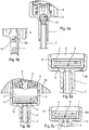
- FIGS. 2a and 2b show a second embodiment of the invention, wherein the movable member 3 is also in the form of a disk, a pellet or a washer, which is however not perforated, but grooved.
- the two faces 31 and 32 are provided with grooves 33 and 34, here in the form of a cross.
- the crosses formed by the grooves are shifted from one side to the other, so as not to weaken the disc.
- the disk rests on its seat 12 in a sealed manner, except at the level of the grooves 33 which extend at the level of the valve seat 12.
- the grooves 33 or 34 create a sealing defect at the level of the valve seat 12.
- these grooves 33, 34 constitute a return passage allowing a portion of the fluid product stored and pressurized in the pump chamber C to be returned to the reservoir through the inlet I and the dip tube T.
- a third embodiment of the invention implementing a movable member 4 in the form of a ball provided with grooves 43.
- the grooves 43 create a defect sealing the inlet valve, as the grooves 33 or 34 of the previous embodiment.
- the grooves 43 constitute a return passage allowing a portion of the fluid product stored and pressurized in the pump chamber C to be returned to the fluid reservoir.
- the movable member 5 is a perfectly spherical ball that is conventional based on a frustoconical valve seat 15 provided with at least one groove 151, which creates a defect of sealing, and thus constitutes a return passage for a portion of the fluid product stored and pressurized in the pump chamber C.
- FIGS. 5a, 5b, 5c , 6a and 6b show embodiments in which there are provided return passages which can be described as "additional”, in that they can be implemented cumulatively with the return passages of the figures 1a , 1b1 2a , 2b, 3a, 3b , 4a, 4b formed at the inlet flap.
- FIG. 5a a fifth embodiment of the invention can be seen in which the pump body B is pierced by a direct bore B1 which directly communicates the pump chamber C with the interior of the tank R.
- the direct bore B1 here is located in close proximity to the movable member 6 of the inlet valve which is in the form of a conventional disc.
- the pump body B is also pierced with a direct bore B2 which is formed at the sliding shaft F.
- the piston K will pass over the bore direct B2 and isolate it from the pump chamber C.
- the direct bore B3 is made at the lower end of the sliding shaft F at the height of the travel limiter J.
- the pump body B is wrapped by an outer sleeve E which surrounds even the fluid product inlet I, preferably from waterproof way.
- the fluid product stored and pressurized in the pump chamber C can escape to regain the dip tube T through a bypass path which comprises a first internal bore B41 made near the movable member 6 of the valve d the inlet, an annular space B43 formed between the pump body B and the sleeve E and another internal bore B42 made in the fluid product inlet I and which communicates directly with the outlet of the dip tube T.
- This return passage allows thus bypassing or shunting the inlet valve by directly connecting the pump chamber C to the dip tube T.
- the figure 6b shows an alternative embodiment of the figure 6a which also uses an outer sleeve E 'which surrounds the pump body B.
- the latter is pierced with a first internal bore B51 and a second internal bore B52 at the inlet I. These two internal bores are connected by an intermediate space B53 so that the pump chamber C directly connects the plunger tube T bypassing or shunting the inlet valve formed by a ball 5 resting on a frustoconical valve 15.
- the doses of fluid dispensed at each actuation of the pump are generally of the order of 50 microliters to 150 microliters.
- the present invention can reduce the volume of fluid dispensed to about 50 microliters, or even about 10 microliters, a reduction of about 50% to 90%, while maintaining of course the total stroke of the pump.
- the return passage which can be in the form of one (or more) channel, hole, groove, bleed, path, etc. may have a single or cumulative cross section of the order of 0.03 mm 2 (0.1 mm diameter) to 0.5 mm 2 (0.8 mm diameter), with a preferred section of about 0.1 mm 2 .
Claims (15)
- Manuelle Pumpe (P) zum Ausgeben eines fluiden Produkts, wobei diese Pumpe dazu ausgelegt ist, mit einem Behälter für ein fluides Produkt (R) verbunden zu werden, um so einen Spender für fluides Produkt zu bilden, wobei die Pumpe (P) ein Pumpengehäuse (B) umfasst, welches einen Gleitzylinder (F) für einen Kolben (K) in einem Stück mit einer Betätigungsstange (S) definiert, wobei die Pumpe (P) eine Pumpenkammer (C) umfasst, in der bei jeder Betätigung eine Dosis von fluidem Produkt unter Druck gesetzt wird, wobei die Pumpe (P) eine Auslassklappe (V) umfasst, die zwischen der Pumpenkammer (C) und einer Ausgabeöffnung (O) zum Austreiben des fluiden Produkts aus der Pumpenkammer (C) angeordnet ist, wobei die Pumpe (P) eine Einlassklappe (2, 12; 3, 12; 4, 14; 5, 15; 6, 12) umfasst, die zwischen der Pumpenkammer (C) und einem Einlass (I) der Pumpe (P) angeordnet ist, um fluides Produkt aus dem Behälter (R) in die Pumpenkammer (C) einzulassen, wobei die Einlassklappe ein bewegliches Bauteil (2; 3; 4; 5; 6) umfasst, welches wahlweise auf einem Klappensitz (12; 14; 15), einem Rückflussdurchgang (23; 33, 34; 43; 151) ruht, wodurch es einem Teil des fluiden Produkts, das in der Pumpenkammer (C) unter Druck gesetzt ist, ermöglicht wird, zu entweichen, ohne die Auslassklappe (V) zu passieren, wobei der Rückflussdurchgang (23; 33, 34; 43; 151) eine Dichtigkeitsunterbrechung an der Einlassklappe (2, 12; 3, 12; 4, 14; 5, 15; 6, 12) bildet,
dadurch gekennzeichnet, dass der Rückflussdurchgang (23; 33, 34; 43) derart durch die Einlassklappe (2, 12; 3, 12; 4, 14; 5, 15; 6, 12) gebildet ist, dass die Einlassklappe somit spitz zulaufend ist. - Manuelle Pumpe (P) nach Anspruch 1, wobei der Rückflussdurchgang (23; 33, 34; 43) durch das bewegliche Bauteil (2; 3; 4) gebildet ist.
- Manuelle Pumpe (P) nach Anspruch 1 oder 2, wobei der Rückflussdurchgang mindestens eine Nut (33, 34; 43) umfasst, die an dem beweglichen Bauteil (3; 4) gebildet ist, die mit seinem Klappensitz (12; 14) in Kontakt kommt.
- Manuelle Pumpe (P) nach Anspruch 1, 2 oder 3, wobei der Rückflussdurchgang ein Loch (23) umfasst, welches das bewegliche Bauteil (2) quert, das vorteilhafterweise in Form einer Scheibe vorliegt.
- Manuelle Pumpe (P) nach einem der vorhergehenden Ansprüche, wobei der Rückflussdurchgang durch den Klappensitz (15) insbesondere in Form mindestens eines Einschnitts (151) gebildet ist.
- Manuelle Pumpe (P) nach einem der vorhergehenden Ansprüche, wobei ein zusätzlicher Rückflussdurchgang (B1; B2; B3; B41, B42, B43; B51, B52, B53) durch das Pumpengehäuse (B) gebildet ist.
- Manuelle Pumpe (P) nach Anspruch 6, wobei der zusätzliche Rückflussdurchgang eine direkte Ausbohrung (B1; B2; B3) umfasst, die die Dicke der Wand des Pumpengehäuses (B) quert und die Pumpenkammer (C) direkt mit dem Behälter (R) verbindet.
- Manuelle Pumpe (P) nach Anspruch 6, wobei das Pumpengehäuse (B) ein Tauchrohr (T) umfasst, das mit dem Einlass (I) der Pumpe (P) verbunden ist, wobei der zusätzliche Rückflussdurchgang einen Ablenkweg (B41, B42, B43; B51, B52, B53) umfasst, der die Pumpenkammer (C) mit dem Tauchrohr (T) verbindet, ohne die Einlassklappe zu passieren.
- Manuelle Pumpe (P) nach Anspruch 8, wobei die Pumpe (P) ein externes Futteral (E) umfasst, welches das Pumpengehäuse (B) umgibt, wobei sich der Ablenkweg (B41, B42, B43; B51, B52, B53) teilweise zwischen dem Pumpengehäuse (B) und dem externen Futteral (E; E') erstreckt und vorteilhafterweise mindestens eine interne Ausbohrung (B41, B42; B51, B52) umfasst, die die Dicke der Wand des Pumpengehäuses (B) quert.
- Manuelle Pumpe (P) nach Anspruch 6, 7 oder 8, wobei der zusätzliche Rückflussdurchgang (B2; B51) in dem Gleitzylinder (F) gebildet ist.
- Manuelle Pumpe (P) nach einem der vorhergehenden Ansprüche, wobei etwa 50 % bis 90 % der Dosis des in der Pumpenkammer (C) unter Druck gesetzten fluiden Produkts über den Rückflussdurchgang (23; 33, 34; 43; 151) entweicht.
- Manuelle Pumpe (P) nach einem der Ansprüche 6 bis 10, wobei etwa 50 % bis 90 % der Dosis des in der Pumpenkammer (C) unter Druck gesetzten fluiden Produkts durch den Rückflussdurchgang (23; 33, 34; 43; 151) und gegebenenfalls den zusätzlichen Rückflussdurchgang (B1; B2; B3; B41, B42, B43; B51, B52, B53) entweichen.
- Manuelle Pumpe (P) nach einem der vorhergehenden Ansprüche, wobei der Rückflussdurchgang (23; 33, 34; 43; 151) einen alleinigen oder kumulierten Querschnitt im Bereich von 0,03 mm2 bis 0,5 mm2 mit einem bevorzugten Querschnitt von etwa 0,1 mm2 aufweist.
- Manuelle Pumpe (P) nach einem der Ansprüche 6 bis 10, wobei der Rückflussdurchgang (23; 33, 34; 43; 151) und gegebenenfalls der zusätzliche Rückflussdurchgang (B1; B2; B3; B41, B42, B43; B51, B52, B53) einen alleinigen oder kumulierten Querschnitt im Bereich von 0,03 mm2 bis 0,5 mm2, mit einem bevorzugten Querschnitt von etwa 0,1 mm2 aufweisen.
- Spender für ein fluides Produkt, umfassend einen Behälter für ein fluides Produkt (R), auf dem eine manuelle Pumpe (P) nach einem der vorhergehenden Ansprüche montiert ist, wobei es der Rückflussdurchgang (23; 33, 34; 43; 151) einem Teil des in der Pumpenkammer (C) unter Druck gesetzten fluiden Produkts ermöglicht, direkt oder indirekt in den Behälter für ein fluides Produkt (R) zurückgeführt zu werden.
Applications Claiming Priority (2)
| Application Number | Priority Date | Filing Date | Title |
|---|---|---|---|
| FR1461018A FR3028571B1 (fr) | 2014-11-14 | 2014-11-14 | Pompe manuelle |
| PCT/FR2015/053066 WO2016075417A1 (fr) | 2014-11-14 | 2015-11-13 | Pompe manuelle |
Publications (2)
| Publication Number | Publication Date |
|---|---|
| EP3218602A1 EP3218602A1 (de) | 2017-09-20 |
| EP3218602B1 true EP3218602B1 (de) | 2019-04-10 |
Family
ID=53269535
Family Applications (1)
| Application Number | Title | Priority Date | Filing Date |
|---|---|---|---|
| EP15817440.9A Active EP3218602B1 (de) | 2014-11-14 | 2015-11-13 | Manuelle pumpe |
Country Status (6)
| Country | Link |
|---|---|
| US (1) | US10385843B2 (de) |
| EP (1) | EP3218602B1 (de) |
| BR (1) | BR112017008398B1 (de) |
| ES (1) | ES2725433T3 (de) |
| FR (1) | FR3028571B1 (de) |
| WO (1) | WO2016075417A1 (de) |
Families Citing this family (2)
| Publication number | Priority date | Publication date | Assignee | Title |
|---|---|---|---|---|
| FR3033844B1 (fr) * | 2015-03-20 | 2018-08-10 | Aptar France Sas | Pompe manuelle. |
| DE102016114456A1 (de) * | 2016-08-04 | 2018-02-08 | Rpc Bramlage Gmbh | Fingerspraypumpe sowie Düsenkopf für eine Sprühpumpe |
Family Cites Families (19)
| Publication number | Priority date | Publication date | Assignee | Title |
|---|---|---|---|---|
| FR2719084B1 (fr) | 1994-04-22 | 1996-07-12 | Valois Sa | Dispositif de réglage du volume d'une chambre de pompe d'une pompe à précompression. |
| JP3693411B2 (ja) * | 1995-08-21 | 2005-09-07 | 花王株式会社 | 容器 |
| GB9724223D0 (en) * | 1997-11-18 | 1998-01-14 | Pa Consulting Services | Drug delivery device |
| FR2796050B1 (fr) * | 1999-07-09 | 2002-01-25 | Sofab | Distributeur de produits liquides a corps en deux parties |
| KR200233932Y1 (ko) * | 2001-01-22 | 2001-09-25 | 강성일 | 배출 장치 및 그를 이용한 화장품 용기 |
| JP3942020B2 (ja) * | 2002-05-23 | 2007-07-11 | 株式会社吉野工業所 | 蓄圧式ポンプおよびそのモジュール |
| US6685062B1 (en) * | 2002-09-16 | 2004-02-03 | Yon Woo Corporation | Dispenser pump |
| FR2862107B1 (fr) * | 2003-11-07 | 2006-02-10 | Valois Sas | Pompe de distribution de produit fluide. |
| US7654418B2 (en) * | 2004-08-30 | 2010-02-02 | Rieke Corporation | Airless dispensing pump |
| TWM291409U (en) * | 2005-11-25 | 2006-06-01 | Yih Tai Galss Ind Co Ltd | Piston device and liquid/gas suction device using the piston device and foam generation device |
| FR2898818B1 (fr) * | 2006-03-22 | 2008-08-22 | Valois Sas | Pompe de distribution de produit fluide |
| CN100494008C (zh) * | 2006-06-15 | 2009-06-03 | 丁要武 | 弹簧外置式乳液泵 |
| FR2910449B1 (fr) * | 2006-12-22 | 2009-03-06 | Rexam Dispensing Systems Sas | Pompe compacte a capacite de rotulage du gicleur par rapport au piston. |
| WO2010082771A2 (ko) * | 2009-01-14 | 2010-07-22 | Kang Sungil | 내용물 배출펌프 |
| KR101233080B1 (ko) * | 2011-09-20 | 2013-02-14 | (주)연우 | 스프레이 펌프 |
| KR101364450B1 (ko) * | 2012-03-22 | 2014-02-20 | (주)연우 | 진공펌프가 구비된 크림타입 화장품용기 |
| US10641260B2 (en) * | 2012-10-31 | 2020-05-05 | Parker-Hannifin Corporation | Pump/compressor valve seat |
| US9114416B2 (en) * | 2013-05-23 | 2015-08-25 | Jae Sam BYEON | Nozzle opening/shutting device for airless type cosmetic vessel |
| FR3033844B1 (fr) * | 2015-03-20 | 2018-08-10 | Aptar France Sas | Pompe manuelle. |
-
2014
- 2014-11-14 FR FR1461018A patent/FR3028571B1/fr active Active
-
2015
- 2015-11-13 US US15/525,363 patent/US10385843B2/en active Active
- 2015-11-13 ES ES15817440T patent/ES2725433T3/es active Active
- 2015-11-13 EP EP15817440.9A patent/EP3218602B1/de active Active
- 2015-11-13 BR BR112017008398-1A patent/BR112017008398B1/pt active IP Right Grant
- 2015-11-13 WO PCT/FR2015/053066 patent/WO2016075417A1/fr active Application Filing
Non-Patent Citations (1)
| Title |
|---|
| None * |
Also Published As
| Publication number | Publication date |
|---|---|
| BR112017008398B1 (pt) | 2022-09-06 |
| BR112017008398A2 (pt) | 2018-06-19 |
| FR3028571B1 (fr) | 2019-09-13 |
| WO2016075417A1 (fr) | 2016-05-19 |
| US20180017051A1 (en) | 2018-01-18 |
| EP3218602A1 (de) | 2017-09-20 |
| US10385843B2 (en) | 2019-08-20 |
| ES2725433T3 (es) | 2019-09-24 |
| FR3028571A1 (fr) | 2016-05-20 |
Similar Documents
| Publication | Publication Date | Title |
|---|---|---|
| EP0757592B1 (de) | Pumpe mit vordruckaufbau | |
| EP2906484B1 (de) | Dosierventil zur abgabe eines aerosols | |
| FR2999960A1 (fr) | Distributeur de produit fluide rechargeable. | |
| EP2922638B1 (de) | Ausgabeelement für ein flüssigprodukt | |
| FR3000944A1 (fr) | Distributeur de produit fluide. | |
| EP3592470B1 (de) | Vorrichtung zur abgabe eines produkts mit verbesserter auslösung | |
| EP1914006A2 (de) | Pumpe mit Entlüftungsmitteln | |
| EP3218602B1 (de) | Manuelle pumpe | |
| EP1194247B1 (de) | Pumpe mit druckaufbau | |
| EP1497039B1 (de) | Abgabepumpe für medien | |
| FR3033844A1 (fr) | Pompe manuelle. | |
| EP3609623B1 (de) | Nachfüllbarer flüssigproduktspender | |
| EP3303177B1 (de) | Dosierventilbaugruppe und gussform zur herstellung solch einer ventilbaugruppe | |
| EP4031288B1 (de) | Hochdruck-vorverdichtungspumpe | |
| FR3005431A1 (fr) | Distributeur de produit fluide. | |
| EP3969751B1 (de) | Verfahren zur montage einer hochdruckvorverdichtungspumpe | |
| EP1590097A1 (de) | Fluidabgabevorrichtung und spender mit einer solchen vorrichtung | |
| WO2020229758A1 (fr) | Pompe a precompression haute pression | |
| FR2857340A1 (fr) | Organe de distribution de produit fluide et distributeur comprenant un tel organe |
Legal Events
| Date | Code | Title | Description |
|---|---|---|---|
| STAA | Information on the status of an ep patent application or granted ep patent |
Free format text: STATUS: THE INTERNATIONAL PUBLICATION HAS BEEN MADE |
|
| PUAI | Public reference made under article 153(3) epc to a published international application that has entered the european phase |
Free format text: ORIGINAL CODE: 0009012 |
|
| STAA | Information on the status of an ep patent application or granted ep patent |
Free format text: STATUS: REQUEST FOR EXAMINATION WAS MADE |
|
| 17P | Request for examination filed |
Effective date: 20170612 |
|
| AK | Designated contracting states |
Kind code of ref document: A1 Designated state(s): AL AT BE BG CH CY CZ DE DK EE ES FI FR GB GR HR HU IE IS IT LI LT LU LV MC MK MT NL NO PL PT RO RS SE SI SK SM TR |
|
| AX | Request for extension of the european patent |
Extension state: BA ME |
|
| DAV | Request for validation of the european patent (deleted) | ||
| DAX | Request for extension of the european patent (deleted) | ||
| STAA | Information on the status of an ep patent application or granted ep patent |
Free format text: STATUS: EXAMINATION IS IN PROGRESS |
|
| 17Q | First examination report despatched |
Effective date: 20180411 |
|
| REG | Reference to a national code |
Ref country code: DE Ref legal event code: R079 Ref document number: 602015028204 Country of ref document: DE Free format text: PREVIOUS MAIN CLASS: F04B0009140000 Ipc: F04B0023020000 |
|
| GRAP | Despatch of communication of intention to grant a patent |
Free format text: ORIGINAL CODE: EPIDOSNIGR1 |
|
| STAA | Information on the status of an ep patent application or granted ep patent |
Free format text: STATUS: GRANT OF PATENT IS INTENDED |
|
| RIC1 | Information provided on ipc code assigned before grant |
Ipc: F04B 53/16 20060101ALI20181002BHEP Ipc: F04B 23/02 20060101AFI20181002BHEP Ipc: F04B 9/14 20060101ALI20181002BHEP Ipc: F04B 53/14 20060101ALI20181002BHEP Ipc: B05B 11/00 20060101ALI20181002BHEP Ipc: F04B 49/24 20060101ALI20181002BHEP Ipc: F04B 49/035 20060101ALI20181002BHEP Ipc: F04B 53/10 20060101ALI20181002BHEP |
|
| INTG | Intention to grant announced |
Effective date: 20181105 |
|
| GRAS | Grant fee paid |
Free format text: ORIGINAL CODE: EPIDOSNIGR3 |
|
| GRAA | (expected) grant |
Free format text: ORIGINAL CODE: 0009210 |
|
| STAA | Information on the status of an ep patent application or granted ep patent |
Free format text: STATUS: THE PATENT HAS BEEN GRANTED |
|
| AK | Designated contracting states |
Kind code of ref document: B1 Designated state(s): AL AT BE BG CH CY CZ DE DK EE ES FI FR GB GR HR HU IE IS IT LI LT LU LV MC MK MT NL NO PL PT RO RS SE SI SK SM TR |
|
| REG | Reference to a national code |
Ref country code: GB Ref legal event code: FG4D Free format text: NOT ENGLISH |
|
| REG | Reference to a national code |
Ref country code: CH Ref legal event code: EP Ref country code: AT Ref legal event code: REF Ref document number: 1119022 Country of ref document: AT Kind code of ref document: T Effective date: 20190415 |
|
| REG | Reference to a national code |
Ref country code: IE Ref legal event code: FG4D Free format text: LANGUAGE OF EP DOCUMENT: FRENCH |
|
| REG | Reference to a national code |
Ref country code: DE Ref legal event code: R096 Ref document number: 602015028204 Country of ref document: DE |
|
| REG | Reference to a national code |
Ref country code: NL Ref legal event code: MP Effective date: 20190410 |
|
| REG | Reference to a national code |
Ref country code: LT Ref legal event code: MG4D |
|
| REG | Reference to a national code |
Ref country code: AT Ref legal event code: MK05 Ref document number: 1119022 Country of ref document: AT Kind code of ref document: T Effective date: 20190410 |
|
| REG | Reference to a national code |
Ref country code: ES Ref legal event code: FG2A Ref document number: 2725433 Country of ref document: ES Kind code of ref document: T3 Effective date: 20190924 |
|
| PG25 | Lapsed in a contracting state [announced via postgrant information from national office to epo] |
Ref country code: NL Free format text: LAPSE BECAUSE OF FAILURE TO SUBMIT A TRANSLATION OF THE DESCRIPTION OR TO PAY THE FEE WITHIN THE PRESCRIBED TIME-LIMIT Effective date: 20190410 |
|
| PG25 | Lapsed in a contracting state [announced via postgrant information from national office to epo] |
Ref country code: AL Free format text: LAPSE BECAUSE OF FAILURE TO SUBMIT A TRANSLATION OF THE DESCRIPTION OR TO PAY THE FEE WITHIN THE PRESCRIBED TIME-LIMIT Effective date: 20190410 Ref country code: NO Free format text: LAPSE BECAUSE OF FAILURE TO SUBMIT A TRANSLATION OF THE DESCRIPTION OR TO PAY THE FEE WITHIN THE PRESCRIBED TIME-LIMIT Effective date: 20190710 Ref country code: FI Free format text: LAPSE BECAUSE OF FAILURE TO SUBMIT A TRANSLATION OF THE DESCRIPTION OR TO PAY THE FEE WITHIN THE PRESCRIBED TIME-LIMIT Effective date: 20190410 Ref country code: SE Free format text: LAPSE BECAUSE OF FAILURE TO SUBMIT A TRANSLATION OF THE DESCRIPTION OR TO PAY THE FEE WITHIN THE PRESCRIBED TIME-LIMIT Effective date: 20190410 Ref country code: PT Free format text: LAPSE BECAUSE OF FAILURE TO SUBMIT A TRANSLATION OF THE DESCRIPTION OR TO PAY THE FEE WITHIN THE PRESCRIBED TIME-LIMIT Effective date: 20190910 Ref country code: HR Free format text: LAPSE BECAUSE OF FAILURE TO SUBMIT A TRANSLATION OF THE DESCRIPTION OR TO PAY THE FEE WITHIN THE PRESCRIBED TIME-LIMIT Effective date: 20190410 Ref country code: LT Free format text: LAPSE BECAUSE OF FAILURE TO SUBMIT A TRANSLATION OF THE DESCRIPTION OR TO PAY THE FEE WITHIN THE PRESCRIBED TIME-LIMIT Effective date: 20190410 |
|
| PG25 | Lapsed in a contracting state [announced via postgrant information from national office to epo] |
Ref country code: RS Free format text: LAPSE BECAUSE OF FAILURE TO SUBMIT A TRANSLATION OF THE DESCRIPTION OR TO PAY THE FEE WITHIN THE PRESCRIBED TIME-LIMIT Effective date: 20190410 Ref country code: BG Free format text: LAPSE BECAUSE OF FAILURE TO SUBMIT A TRANSLATION OF THE DESCRIPTION OR TO PAY THE FEE WITHIN THE PRESCRIBED TIME-LIMIT Effective date: 20190710 Ref country code: PL Free format text: LAPSE BECAUSE OF FAILURE TO SUBMIT A TRANSLATION OF THE DESCRIPTION OR TO PAY THE FEE WITHIN THE PRESCRIBED TIME-LIMIT Effective date: 20190410 Ref country code: LV Free format text: LAPSE BECAUSE OF FAILURE TO SUBMIT A TRANSLATION OF THE DESCRIPTION OR TO PAY THE FEE WITHIN THE PRESCRIBED TIME-LIMIT Effective date: 20190410 Ref country code: GR Free format text: LAPSE BECAUSE OF FAILURE TO SUBMIT A TRANSLATION OF THE DESCRIPTION OR TO PAY THE FEE WITHIN THE PRESCRIBED TIME-LIMIT Effective date: 20190711 |
|
| PG25 | Lapsed in a contracting state [announced via postgrant information from national office to epo] |
Ref country code: IS Free format text: LAPSE BECAUSE OF FAILURE TO SUBMIT A TRANSLATION OF THE DESCRIPTION OR TO PAY THE FEE WITHIN THE PRESCRIBED TIME-LIMIT Effective date: 20190810 Ref country code: AT Free format text: LAPSE BECAUSE OF FAILURE TO SUBMIT A TRANSLATION OF THE DESCRIPTION OR TO PAY THE FEE WITHIN THE PRESCRIBED TIME-LIMIT Effective date: 20190410 |
|
| REG | Reference to a national code |
Ref country code: DE Ref legal event code: R097 Ref document number: 602015028204 Country of ref document: DE |
|
| PG25 | Lapsed in a contracting state [announced via postgrant information from national office to epo] |
Ref country code: CZ Free format text: LAPSE BECAUSE OF FAILURE TO SUBMIT A TRANSLATION OF THE DESCRIPTION OR TO PAY THE FEE WITHIN THE PRESCRIBED TIME-LIMIT Effective date: 20190410 Ref country code: RO Free format text: LAPSE BECAUSE OF FAILURE TO SUBMIT A TRANSLATION OF THE DESCRIPTION OR TO PAY THE FEE WITHIN THE PRESCRIBED TIME-LIMIT Effective date: 20190410 Ref country code: EE Free format text: LAPSE BECAUSE OF FAILURE TO SUBMIT A TRANSLATION OF THE DESCRIPTION OR TO PAY THE FEE WITHIN THE PRESCRIBED TIME-LIMIT Effective date: 20190410 Ref country code: DK Free format text: LAPSE BECAUSE OF FAILURE TO SUBMIT A TRANSLATION OF THE DESCRIPTION OR TO PAY THE FEE WITHIN THE PRESCRIBED TIME-LIMIT Effective date: 20190410 Ref country code: SK Free format text: LAPSE BECAUSE OF FAILURE TO SUBMIT A TRANSLATION OF THE DESCRIPTION OR TO PAY THE FEE WITHIN THE PRESCRIBED TIME-LIMIT Effective date: 20190410 |
|
| PLBE | No opposition filed within time limit |
Free format text: ORIGINAL CODE: 0009261 |
|
| STAA | Information on the status of an ep patent application or granted ep patent |
Free format text: STATUS: NO OPPOSITION FILED WITHIN TIME LIMIT |
|
| PG25 | Lapsed in a contracting state [announced via postgrant information from national office to epo] |
Ref country code: IT Free format text: LAPSE BECAUSE OF FAILURE TO SUBMIT A TRANSLATION OF THE DESCRIPTION OR TO PAY THE FEE WITHIN THE PRESCRIBED TIME-LIMIT Effective date: 20190410 Ref country code: SM Free format text: LAPSE BECAUSE OF FAILURE TO SUBMIT A TRANSLATION OF THE DESCRIPTION OR TO PAY THE FEE WITHIN THE PRESCRIBED TIME-LIMIT Effective date: 20190410 |
|
| 26N | No opposition filed |
Effective date: 20200113 |
|
| PG25 | Lapsed in a contracting state [announced via postgrant information from national office to epo] |
Ref country code: TR Free format text: LAPSE BECAUSE OF FAILURE TO SUBMIT A TRANSLATION OF THE DESCRIPTION OR TO PAY THE FEE WITHIN THE PRESCRIBED TIME-LIMIT Effective date: 20190410 |
|
| PG25 | Lapsed in a contracting state [announced via postgrant information from national office to epo] |
Ref country code: SI Free format text: LAPSE BECAUSE OF FAILURE TO SUBMIT A TRANSLATION OF THE DESCRIPTION OR TO PAY THE FEE WITHIN THE PRESCRIBED TIME-LIMIT Effective date: 20190410 |
|
| REG | Reference to a national code |
Ref country code: DE Ref legal event code: R119 Ref document number: 602015028204 Country of ref document: DE |
|
| REG | Reference to a national code |
Ref country code: CH Ref legal event code: PL |
|
| PG25 | Lapsed in a contracting state [announced via postgrant information from national office to epo] |
Ref country code: LU Free format text: LAPSE BECAUSE OF NON-PAYMENT OF DUE FEES Effective date: 20191113 Ref country code: LI Free format text: LAPSE BECAUSE OF NON-PAYMENT OF DUE FEES Effective date: 20191130 Ref country code: CH Free format text: LAPSE BECAUSE OF NON-PAYMENT OF DUE FEES Effective date: 20191130 Ref country code: MC Free format text: LAPSE BECAUSE OF FAILURE TO SUBMIT A TRANSLATION OF THE DESCRIPTION OR TO PAY THE FEE WITHIN THE PRESCRIBED TIME-LIMIT Effective date: 20190410 |
|
| REG | Reference to a national code |
Ref country code: BE Ref legal event code: MM Effective date: 20191130 |
|
| GBPC | Gb: european patent ceased through non-payment of renewal fee |
Effective date: 20191113 |
|
| PG25 | Lapsed in a contracting state [announced via postgrant information from national office to epo] |
Ref country code: DE Free format text: LAPSE BECAUSE OF NON-PAYMENT OF DUE FEES Effective date: 20200603 Ref country code: GB Free format text: LAPSE BECAUSE OF NON-PAYMENT OF DUE FEES Effective date: 20191113 Ref country code: IE Free format text: LAPSE BECAUSE OF NON-PAYMENT OF DUE FEES Effective date: 20191113 |
|
| PG25 | Lapsed in a contracting state [announced via postgrant information from national office to epo] |
Ref country code: BE Free format text: LAPSE BECAUSE OF NON-PAYMENT OF DUE FEES Effective date: 20191130 |
|
| PG25 | Lapsed in a contracting state [announced via postgrant information from national office to epo] |
Ref country code: CY Free format text: LAPSE BECAUSE OF FAILURE TO SUBMIT A TRANSLATION OF THE DESCRIPTION OR TO PAY THE FEE WITHIN THE PRESCRIBED TIME-LIMIT Effective date: 20190410 |
|
| PG25 | Lapsed in a contracting state [announced via postgrant information from national office to epo] |
Ref country code: MT Free format text: LAPSE BECAUSE OF FAILURE TO SUBMIT A TRANSLATION OF THE DESCRIPTION OR TO PAY THE FEE WITHIN THE PRESCRIBED TIME-LIMIT Effective date: 20190410 Ref country code: HU Free format text: LAPSE BECAUSE OF FAILURE TO SUBMIT A TRANSLATION OF THE DESCRIPTION OR TO PAY THE FEE WITHIN THE PRESCRIBED TIME-LIMIT; INVALID AB INITIO Effective date: 20151113 |
|
| PG25 | Lapsed in a contracting state [announced via postgrant information from national office to epo] |
Ref country code: MK Free format text: LAPSE BECAUSE OF FAILURE TO SUBMIT A TRANSLATION OF THE DESCRIPTION OR TO PAY THE FEE WITHIN THE PRESCRIBED TIME-LIMIT Effective date: 20190410 |
|
| P01 | Opt-out of the competence of the unified patent court (upc) registered |
Effective date: 20230526 |
|
| PGFP | Annual fee paid to national office [announced via postgrant information from national office to epo] |
Ref country code: ES Payment date: 20231218 Year of fee payment: 9 |
|
| PGFP | Annual fee paid to national office [announced via postgrant information from national office to epo] |
Ref country code: FR Payment date: 20231127 Year of fee payment: 9 |