EP1865571A1 - Fensterscheibe mit Aufbau aus leitfähiger Sinterkeramik und Herstellungsverfahren dafür - Google Patents
Fensterscheibe mit Aufbau aus leitfähiger Sinterkeramik und Herstellungsverfahren dafür Download PDFInfo
- Publication number
- EP1865571A1 EP1865571A1 EP07007392A EP07007392A EP1865571A1 EP 1865571 A1 EP1865571 A1 EP 1865571A1 EP 07007392 A EP07007392 A EP 07007392A EP 07007392 A EP07007392 A EP 07007392A EP 1865571 A1 EP1865571 A1 EP 1865571A1
- Authority
- EP
- European Patent Office
- Prior art keywords
- sintered body
- conductive ceramics
- window glass
- silver
- conductive
- Prior art date
- Legal status (The legal status is an assumption and is not a legal conclusion. Google has not performed a legal analysis and makes no representation as to the accuracy of the status listed.)
- Withdrawn
Links
- 239000005357 flat glass Substances 0.000 title claims abstract description 62
- 238000000034 method Methods 0.000 title claims description 9
- 238000004519 manufacturing process Methods 0.000 title claims description 7
- 239000011521 glass Substances 0.000 claims abstract description 45
- 229910052709 silver Inorganic materials 0.000 claims abstract description 35
- 239000004332 silver Substances 0.000 claims abstract description 35
- 229940100890 silver compound Drugs 0.000 claims abstract description 18
- 150000003379 silver compounds Chemical class 0.000 claims abstract description 18
- BQCADISMDOOEFD-UHFFFAOYSA-N Silver Chemical compound [Ag] BQCADISMDOOEFD-UHFFFAOYSA-N 0.000 claims description 27
- 239000002344 surface layer Substances 0.000 claims description 24
- 238000005498 polishing Methods 0.000 claims description 14
- 229910021607 Silver chloride Inorganic materials 0.000 claims description 13
- HKZLPVFGJNLROG-UHFFFAOYSA-M silver monochloride Chemical compound [Cl-].[Ag+] HKZLPVFGJNLROG-UHFFFAOYSA-M 0.000 claims description 13
- 239000000126 substance Substances 0.000 claims description 13
- 239000010410 layer Substances 0.000 claims description 11
- 238000005245 sintering Methods 0.000 claims description 8
- -1 silver halide Chemical class 0.000 claims description 7
- NDVLTYZPCACLMA-UHFFFAOYSA-N silver oxide Chemical compound [O-2].[Ag+].[Ag+] NDVLTYZPCACLMA-UHFFFAOYSA-N 0.000 claims description 6
- 238000007639 printing Methods 0.000 claims description 4
- XNGYKPINNDWGGF-UHFFFAOYSA-L silver oxalate Chemical compound [Ag+].[Ag+].[O-]C(=O)C([O-])=O XNGYKPINNDWGGF-UHFFFAOYSA-L 0.000 claims description 3
- 229910001923 silver oxide Inorganic materials 0.000 claims description 3
- 229910052946 acanthite Inorganic materials 0.000 claims description 2
- XUARKZBEFFVFRG-UHFFFAOYSA-N silver sulfide Chemical compound [S-2].[Ag+].[Ag+] XUARKZBEFFVFRG-UHFFFAOYSA-N 0.000 claims description 2
- 229940056910 silver sulfide Drugs 0.000 claims description 2
- 239000011347 resin Substances 0.000 description 5
- 229920005989 resin Polymers 0.000 description 5
- 230000008859 change Effects 0.000 description 4
- 238000007654 immersion Methods 0.000 description 4
- 239000002245 particle Substances 0.000 description 4
- XLYOFNOQVPJJNP-UHFFFAOYSA-N water Substances O XLYOFNOQVPJJNP-UHFFFAOYSA-N 0.000 description 4
- 239000000654 additive Substances 0.000 description 3
- 230000000996 additive effect Effects 0.000 description 3
- 239000011230 binding agent Substances 0.000 description 3
- 239000003086 colorant Substances 0.000 description 3
- 239000003960 organic solvent Substances 0.000 description 3
- KZVBBTZJMSWGTK-UHFFFAOYSA-N 1-[2-(2-butoxyethoxy)ethoxy]butane Chemical compound CCCCOCCOCCOCCCC KZVBBTZJMSWGTK-UHFFFAOYSA-N 0.000 description 2
- RSWGJHLUYNHPMX-UHFFFAOYSA-N Abietic-Saeure Natural products C12CCC(C(C)C)=CC2=CCC2C1(C)CCCC2(C)C(O)=O RSWGJHLUYNHPMX-UHFFFAOYSA-N 0.000 description 2
- 239000001856 Ethyl cellulose Substances 0.000 description 2
- ZZSNKZQZMQGXPY-UHFFFAOYSA-N Ethyl cellulose Chemical compound CCOCC1OC(OC)C(OCC)C(OCC)C1OC1C(O)C(O)C(OC)C(CO)O1 ZZSNKZQZMQGXPY-UHFFFAOYSA-N 0.000 description 2
- XEEYBQQBJWHFJM-UHFFFAOYSA-N Iron Chemical compound [Fe] XEEYBQQBJWHFJM-UHFFFAOYSA-N 0.000 description 2
- KHPCPRHQVVSZAH-HUOMCSJISA-N Rosin Natural products O(C/C=C/c1ccccc1)[C@H]1[C@H](O)[C@@H](O)[C@@H](O)[C@@H](CO)O1 KHPCPRHQVVSZAH-HUOMCSJISA-N 0.000 description 2
- 239000005708 Sodium hypochlorite Substances 0.000 description 2
- WUOACPNHFRMFPN-UHFFFAOYSA-N alpha-terpineol Chemical compound CC1=CCC(C(C)(C)O)CC1 WUOACPNHFRMFPN-UHFFFAOYSA-N 0.000 description 2
- 229910052797 bismuth Inorganic materials 0.000 description 2
- JCXGWMGPZLAOME-UHFFFAOYSA-N bismuth atom Chemical compound [Bi] JCXGWMGPZLAOME-UHFFFAOYSA-N 0.000 description 2
- SQIFACVGCPWBQZ-UHFFFAOYSA-N delta-terpineol Natural products CC(C)(O)C1CCC(=C)CC1 SQIFACVGCPWBQZ-UHFFFAOYSA-N 0.000 description 2
- 235000019325 ethyl cellulose Nutrition 0.000 description 2
- 229920001249 ethyl cellulose Polymers 0.000 description 2
- 238000011156 evaluation Methods 0.000 description 2
- 238000000445 field-emission scanning electron microscopy Methods 0.000 description 2
- 229910052736 halogen Inorganic materials 0.000 description 2
- 230000002140 halogenating effect Effects 0.000 description 2
- 150000002367 halogens Chemical class 0.000 description 2
- 238000010438 heat treatment Methods 0.000 description 2
- 239000000463 material Substances 0.000 description 2
- 229910001507 metal halide Inorganic materials 0.000 description 2
- 150000005309 metal halides Chemical class 0.000 description 2
- 239000000049 pigment Substances 0.000 description 2
- 229920000728 polyester Polymers 0.000 description 2
- SUKJFIGYRHOWBL-UHFFFAOYSA-N sodium hypochlorite Chemical compound [Na+].Cl[O-] SUKJFIGYRHOWBL-UHFFFAOYSA-N 0.000 description 2
- 229940116411 terpineol Drugs 0.000 description 2
- KHPCPRHQVVSZAH-UHFFFAOYSA-N trans-cinnamyl beta-D-glucopyranoside Natural products OC1C(O)C(O)C(CO)OC1OCC=CC1=CC=CC=C1 KHPCPRHQVVSZAH-UHFFFAOYSA-N 0.000 description 2
- 229910000314 transition metal oxide Inorganic materials 0.000 description 2
- ZCYVEMRRCGMTRW-UHFFFAOYSA-N 7553-56-2 Chemical compound [I] ZCYVEMRRCGMTRW-UHFFFAOYSA-N 0.000 description 1
- WKBOTKDWSSQWDR-UHFFFAOYSA-N Bromine atom Chemical compound [Br] WKBOTKDWSSQWDR-UHFFFAOYSA-N 0.000 description 1
- 101100150496 Mesoplasma florum (strain ATCC 33453 / NBRC 100688 / NCTC 11704 / L1) smpB gene Proteins 0.000 description 1
- UCKMPCXJQFINFW-UHFFFAOYSA-N Sulphide Chemical compound [S-2] UCKMPCXJQFINFW-UHFFFAOYSA-N 0.000 description 1
- 238000005452 bending Methods 0.000 description 1
- 230000008901 benefit Effects 0.000 description 1
- GDTBXPJZTBHREO-UHFFFAOYSA-N bromine Substances BrBr GDTBXPJZTBHREO-UHFFFAOYSA-N 0.000 description 1
- 229910052794 bromium Inorganic materials 0.000 description 1
- 229910017052 cobalt Inorganic materials 0.000 description 1
- 239000010941 cobalt Substances 0.000 description 1
- GUTLYIVDDKVIGB-UHFFFAOYSA-N cobalt atom Chemical compound [Co] GUTLYIVDDKVIGB-UHFFFAOYSA-N 0.000 description 1
- 238000007865 diluting Methods 0.000 description 1
- 229910052740 iodine Inorganic materials 0.000 description 1
- 239000011630 iodine Substances 0.000 description 1
- 229910052742 iron Inorganic materials 0.000 description 1
- 230000001678 irradiating effect Effects 0.000 description 1
- WPBNNNQJVZRUHP-UHFFFAOYSA-L manganese(2+);methyl n-[[2-(methoxycarbonylcarbamothioylamino)phenyl]carbamothioyl]carbamate;n-[2-(sulfidocarbothioylamino)ethyl]carbamodithioate Chemical compound [Mn+2].[S-]C(=S)NCCNC([S-])=S.COC(=O)NC(=S)NC1=CC=CC=C1NC(=S)NC(=O)OC WPBNNNQJVZRUHP-UHFFFAOYSA-L 0.000 description 1
- 229910044991 metal oxide Inorganic materials 0.000 description 1
- 150000004706 metal oxides Chemical class 0.000 description 1
- 238000012986 modification Methods 0.000 description 1
- 230000004048 modification Effects 0.000 description 1
- 230000008569 process Effects 0.000 description 1
- 230000003014 reinforcing effect Effects 0.000 description 1
- 238000007650 screen-printing Methods 0.000 description 1
- 229910052720 vanadium Inorganic materials 0.000 description 1
- LEONUFNNVUYDNQ-UHFFFAOYSA-N vanadium atom Chemical compound [V] LEONUFNNVUYDNQ-UHFFFAOYSA-N 0.000 description 1
Images



Classifications
-
- H—ELECTRICITY
- H01—ELECTRIC ELEMENTS
- H01Q—ANTENNAS, i.e. RADIO AERIALS
- H01Q1/00—Details of, or arrangements associated with, antennas
- H01Q1/12—Supports; Mounting means
- H01Q1/1271—Supports; Mounting means for mounting on windscreens
-
- C—CHEMISTRY; METALLURGY
- C03—GLASS; MINERAL OR SLAG WOOL
- C03C—CHEMICAL COMPOSITION OF GLASSES, GLAZES OR VITREOUS ENAMELS; SURFACE TREATMENT OF GLASS; SURFACE TREATMENT OF FIBRES OR FILAMENTS MADE FROM GLASS, MINERALS OR SLAGS; JOINING GLASS TO GLASS OR OTHER MATERIALS
- C03C17/00—Surface treatment of glass, not in the form of fibres or filaments, by coating
-
- C—CHEMISTRY; METALLURGY
- C03—GLASS; MINERAL OR SLAG WOOL
- C03C—CHEMICAL COMPOSITION OF GLASSES, GLAZES OR VITREOUS ENAMELS; SURFACE TREATMENT OF GLASS; SURFACE TREATMENT OF FIBRES OR FILAMENTS MADE FROM GLASS, MINERALS OR SLAGS; JOINING GLASS TO GLASS OR OTHER MATERIALS
- C03C17/00—Surface treatment of glass, not in the form of fibres or filaments, by coating
- C03C17/06—Surface treatment of glass, not in the form of fibres or filaments, by coating with metals
Definitions
- the present invention relates to a window glass with a conductive ceramics-sintered body and a method for manufacturing the window glass with the conductive ceramics-sintered body.
- a window glass for use in vehicles or the like which has a conductive ceramics-sintered body such as an antenna wire, a defogger, or the like formed on at least one principal surface (hereinafter referred to as "the print surface") thereof.
- the conductive ceramics-sintered body is formed on the print surface of the window glass by screen-printing a conductive paste-containing silver and a glass binder on the print surface of the window glass in a predetermined pattern and heating the window glass to sinter the conductive paste.
- the conductive ceramic-sintered body appears white as viewed from the print surface side and brownish red as viewed from the surface opposite to the print surface. Deep-colored window glasses are often used in vehicles. Consequently, particularly as viewed from the print surface side, the conductive ceramics-sintered body appears noticeably white and may be unpleasant to the eye.
- a vehicle window glass has been proposed in which a pigment or a coloring agent is added to a conductive paste so that the color of a portion of the window glass in which the conductive ceramics-sintered body is formed exhibits a CIE 1976 psychometric lightness L* value of 50 to 70 as viewed from the print surface side (from the interior) (see, for example, Japanese Laid-Open Patent Publication (Kokai) No. 2001-206056 ) .
- the color of a portion of the window glass in which the conductive ceramics-sintered body is formed exhibits a CIE 1976 psychometric lightness L* value of 50 to 70 as viewed from the print surface side. This is not a sufficiently low lightness. Consequently, the conductive ceramics-sintered body appears noticeably white as viewed from the print surface side.
- the pigment or coloring agent is added to and dispersed in the conductive paste, thereby reducing the content by percentage of silver in the conductive paste, which increases the resistance value of the conductive ceramics-sintered body.
- the present invention provides a window glass with a conductive ceramics-sintered body which has an improved appearance while allowing the conductive ceramics-sintered body to be kept conductive, and a method for manufacturing the window glass with the conductive ceramics-sintered body.
- a window glass with a conductive ceramics-sintered body provides a window glass with a conductive ceramics-sintered body comprising a glass plate and the conductive ceramics-sintered body formed on at least one principal surface of the glass plate and containing silver, characterized in that the conductive ceramics-sintered body contains a silver compound on a surface of the sintered body.
- the conductive ceramics-sintered body can have a surface layer mainly comprising a silver compound on a surface thereof and internally has an internal layer mainly comprising silver.
- the internal layer can contain a silver compound, and the content by percentage of the silver compound in the internal layer is lower than that in the surface layer.
- the surface layer can have a denser structure than the internal layer.
- the conductive ceramics-sintered body can contain silver on at least a part of a surface of the surface layer.
- a portion of the window glass in which the conductive ceramics-sintered body is formed can exhibit a CIE 1976 lightness L* value of at most 50 in a CIE 1976 L*a*b* color system as viewed from a side of the window glass on which the conductive ceramics-sintered body is formed.
- the color of the portion in which the conductive ceramics-sintered body is formed can be made darker and thus unnoticeable. This enables the appearance of the window glass to be improved.
- the portion of the window glass in which the conductive ceramics-sintered body is formed can exhibit a color coordinate a* value of -12 to 12 and a color coordinate b* value of -12 to 12 in the CIE 1976 L*a*b color system as viewed from the side of the window glass on which the conductive ceramics-sintered body is formed.
- the silver compound can contain at least one of silver halide, silver sulfide, silver oxalate, and silver oxide.
- the silver compound can comprise at least one type of silver halide.
- the silver compound can mainly comprise silver chloride.
- the conductive ceramics-sintered body can have a resistivity value of 3 to 70 ⁇ cm.
- a method for manufacturing a window glass with a conductive ceramics-sintered body characterized by comprising a printing step of printing a conductive paste containing silver on at least one principal surface thereof; a sintering step of sintering the printed conductive paste to form a conductive ceramics-sintered body; and a chemically treating step of performing a chemical treatment on the silver on a surface of the conductive ceramics-sintered body formed to convert the silver into a silver compound.
- the window glass manufacturing method can further comprise a polishing step of polishing the surface of the conductive ceramics-sintered body formed.
- FIG. 1 is a view showing the arrangement of a window glass with a conductive ceramics-sintered body according to an embodiment of the present invention
- FIG. 2 is a sectional view of the glass plate shown in FIG . 1 and having an antenna wire formed on its interior surface;
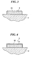
- FIG. 3 is a view which is useful in explaining that silver on a surface of the antenna wire in FIG. 2 has been converted into silver chloride;
- FIG. 4 is a view which is useful in explaining that a surface layer having much silver chloride has been formed on the surface of the antenna wire in FIG. 3;
- FIG. 5 is a view which is useful in explaining that the silver chloride on the surface layer of the antenna wire in FIG. 4 has been partly reduced to sliver;
- FIG. 6 is a view which is useful in explaining a test pattern used in an example of the present invention.
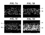
- FIGS. 7A and 7D are views showing the condition of a cross section of a conductive wire in the example of the present invention, FIGS. 7A to 7D showing samples 0 to 3, respectively; and
- FIG. 8A and 8D are views showing the condition of a surface of a conductive wire 13 in the example of the present invention
- FIGS. 8A to 8D shows samples 0 to 3, respectively.
- the present inventors have found the following.
- the conductive ceramics-sintered body comprising a glass plate and the conductive ceramics-sintered body formed on at least one principal surface of the glass plate and containing silver
- the conductive ceramics-sintered body contains a silver compound on a surface of the sintered body
- the appearance of a window glass can be improved with the conductivity of a conductive ceramics-sintered body kept.
- the present invention has been made on the basis of the examination results.
- FIG. 1 is a front view showing the arrangement of a window glass with a conductive ceramics-sintered body according to an embodiment of the present invention.
- a vehicle window glass 1 as a window glass with a conductive ceramics-sintered body comprises a glass plate 2, an antenna wire 3 (conductive ceramics-sintered body) formed on a principal surface which faces the interior of the vehicle (hereinafter referred to as "the interior surface") of the glass plate 2, and a feeding terminal 4 soldered to the antenna wire 3.
- the line width and thickness of the antenna wire 3 are appropriately determined as required.
- the antenna wire 3 is formed on the interior surface of the glass plate 2 as described below.
- a conductive paste is screen-printed on the interior surface of the glass plate 2 in a predetermined pattern using a 200-mesh polyester screen.
- This conductive paste contains silver particles of average particle size 0.1 to 15.0 ⁇ m, a glass binder (crystallized glass and amorphous glass) such as bismuth and having a softening point of 300 to 620 °C, a transition metal oxide containing an oxide of at least one of vanadium, manganese, iron, and cobalt, a resin such as ethylcellulose and a rosin-containing resin, and an additive.
- These components are dispersed in an organic solvent such as terpineol and dibutylcarbitol.
- the amounts of these components based on the conductive paste are 70 to 80 wt% for the silver particles, 1 to 10 wt% for the glass binder and transition metal oxide, 1 to 10 wt% for the resin, 1 to 10 wt% for the additive, and 10 to 20 wt% for the organic solvent.
- the glass plate 2 on which the conductive paste is screen-printed is heated at 600 to 900 °C and thus the conductive paste is sintered to form an antenna wire 3 on the interior surface of the glass plate 2 as shown in FIG. 2.
- This sintering is normally carried out simultaneously with a process for bending and reinforcing the glass plate 2.
- the color of the portion of the window glass in which the antenna wire 3 is formed exhibits a CIE 1976 psychometric lightness L* value of about 70 or more as viewed from the interior surface side. That is, the portion in which the antenna wire 3 is formed appears white as viewed from the interior surface side.
- the surface of the antenna wire 3 is polished and thus smoothed with a polishing material (for example, Steel Wool #0000 manufactured by Nippon Steel Wool Co., Ltd.).
- a polishing material for example, Steel Wool #0000 manufactured by Nippon Steel Wool Co., Ltd.
- the silver on the surface of the antenna wire 3 is then chemically treated. That is, a treatment solution (for example, a 10% water solution of sodium hypochlorite (manufactured by Sigma-Aldrich Japan K. K.) diluted twice) is repeatedly applied to the antenna wire 3 until the antenna wire 3 exhibits a predetermined lightness as viewed from the interior surface side. Application of the treatment solution causes the silver on the surface of the antenna wire 3 to be converted into silver chloride 20 as shown in FIG. 3.
- a treatment solution for example, a 10% water solution of sodium hypochlorite (manufactured by Sigma-Aldrich Japan K. K.) diluted twice
- Application of the treatment solution causes the silver on the surface of the antenna wire 3 to be
- the silver chloride in the surface layer 30 of the antenna wire 3 is partly reduced to sliver 40.
- the interior surface of the glass plate 2 may be irradiated with ultraviolet rays from a metal halide lamp, for example, for 4 minutes.
- the color of the portion of the window glass in which the antenna wire 3 is formed exhibits a CIE 1976 psychometric lightness L* value of at most 50, preferably at most 45, more preferably at most 40 as viewed from the interior surface side. That is, the portion of the window glass in which the antenna wire 3 is formed exhibits a darker color (brownish red to black) than before the chemical treatment as viewed from the interior surface side.
- the antenna wire 3 appears noticeably white.
- the portion of the window glass in which the antenna wire 3 is formed exhibits a color coordinate a* value of -12 to 12, preferably -5 to 5, more preferably 0 to 5 as viewed from the interior surface side.
- the portion of the window glass in which the antenna wire 3 is formed exhibits a color coordinate b* value of -12 to 12, preferably -3 to 3, more preferably -2 to 3 as viewed from the interior surface side.
- the antenna wire 3 has a resistivity value of 3 to 70 ⁇ cm.
- the resistivity value of the antenna wire 3 after the chemical treatment is at most 10 times, preferably at most 3 times, more preferably at most twice as large as that before the chemical treatment.
- the L* value, a* value, and b* value are specified in the method for displaying colors in JIS Z8729-2004 andmeasuredwith a spectrophotometer (CM-3500d manufactured by KONICA MINOLTA HOLDINGS, INC.).
- the resistivity value ⁇ (unit: ⁇ cm) is obtained as follows.
- the film sectional area S (unit: cm2) of the antenna wire 3 is measured with a contact shape measuring instrument (P-10 manufactured by KLA-Tencor Corporation).
- a treatment solution is repeatedly applied to the antenna wire 3 until the antenna wire 3 exhibits a predetermined lightness as viewed from the interior surface. This enables the color of the antenna wire 3 to be made darker and unnoticeable to improve the appearance of the vehicle window glass 1 while keeping the antenna wire 3 conductive.
- the treatment solution is repeatedly applied to the antenna wire 3 to form a surface layer 30 containing much silver chloride on the surface thereof.
- the silver on the surface of the antenna wire 3 may be chemically treated with another halogen such as bromine and iodine to form another surface layer containing much silver halide on the surface of the antenna wire. Chemically treating the silver with the halogen enables the strength of the antenna wire 3 to be maintained. Further, reducing the silver halide enables the tint of the antenna wire 3 as viewed from the interior surface to be adjusted.
- the silver on the surface of the antenna wire 3 may be sulfurized, oxalated, or oxidized to form a surface layer containing much sliver sulfide, silver oxalate, or silver oxide on the surface of the antenna wire 3.
- the conductive ceramics-sintered body is the antenna wire 3.
- the conductive ceramics-sintered body may be a defogger (heating wire) formed on the window glass and the like.
- a conductive paste was screen-printed on one principal surface (hereinafter referred to as "the print surface") of a 200 mm ⁇ 500 mm glass plate 12 (MFL210) using a 200-mesh polyester screen, to arrange ten 100 mm ⁇ 100 mm test patterns shown in FIG. 6, on the principal surface.
- a conductive wire 13 has resistance measured points 13a and 13b (length: 1,000 mm) at which the resistance value is measured.
- the conductive wire 13 has measured portions 14a and 14b of length 40 mm and width 20 mm in which color and lightness are measured.
- the conductive paste contains 70 to 80 wt% of silver particles, 1 to 10 wt% of glass such as bismuth and a metal oxide, 1 to 10 wt% of resin comprising ethylcellulose and a rosin-based resin, 1 to 10 wt% of additive, and 10 to 20 wt% of organic solvent comprising terpineol and dibutylcarbitol.
- the glass plate 12 on which the conductive paste was screen-printed was heated in a sintering furnace for 5 minutes so that the maximum temperature was 620 °C.
- the conductive paste was thus sintered to form a conductive wire 13 on the print surface of the glass plate 12.
- the conductive wire 13 was 0.6 mm in line width and 12.98 ⁇ m in thickness.
- the glass plate 12 was cut into ten 100 mm ⁇ 100 mm samples.
- the surface of the conductive wire 13 was polished and thus smoothed with a polishing material (Steel Wool #0000 manufactured by Nippon Steel Wool Co. , Ltd.).
- the silver on the surface of the conductive wire 13 was then chemically treated. That is, the glass plate 12 on which the conductive wire 13 was formed was immersed in a treatment solution obtained by diluting a 10% water solution of sodium hypochlorite (manufactured by Sigma-Aldrich Japan K. K.) twice. The glass plate 12 was left in the treatment solution for 0.5, 6, or 60 minutes.
- the treatment solution adhering to the glass plate 12 was flushed with flowing water (running water) for 30 seconds. The moisture was then wiped off from the glass plate 12.
- the print surface of the glass plate 12 was then irradiated with ultraviolet rays of wavelength 380 to 420 ⁇ m from a metal halide lamp (UNILEC URM-300 (GL-30301BF-B) manufactured by USHIO INC.) for 4 minutes. The distance between the light source and the print surface was about 2 m.
- Samples 1, 2, and 3 were prepared which had been immersed in the treatment solution for 0.5, 6, and 60 minutes, respectively.
- Sample 0 was also prepared which had been sintered (but not subjected to surface polishing).
- the cross section of the conductive wire 13 was observed with FE-SEM (S4700) manufactured by Hitachi, Ltd. The results are shown in FIG. 7.
- FIGS. 7A to 7D are views showing the condition of a cross section of the conductive wire 13 in the example of the present invention, FIGS. 7A to 7D showing samples 0 to 3, respectively.
- FIGS. 7A to 7D show that when the glass plate 12 on which the conductive wire 13 is formed is immersed in the treatment solution (samples 1 to 3), a surface layer 71 is formed which contains much silver chloride on the surface of the conductive wire 13.
- FIG. 7A shows that the surface layer 71 is not formed on the sintered (not surface-polished) glass plate (sample 0).
- the thickness of the surface layer 71 increases consistently with the time for which the sample is immersed in the treatment solution.
- the surface layer 71 also has a lower porosity than an internal layer 72 and thus has a dense structure.
- Table 1 shows the thickness of the entire conductive wire 13 and the thickness of the surface layer 71 in samples 0 to 3.
- FIG. 8A to 8D are views showing the condition of a surface of the conductive wire 13 in the example of the present invention.
- FIGS. 8A to 8D show samples 0 to 3, respectively.
- FIG. 8A shows that in the sintered (not surface-polished) glass plate (sample 0), recesses and protrusions are present on the surface of the conductive wire 13.
- FIGS. 8B to 8D show that when the glass plate 12 on which the conductive wire 13 is formed is immersed in the treatment solution (samples 1 to 3), the surface is smoothed. Further, the size of silver chloride formed increases consistently with the time for which the sample is immersed in the treatment solution. The surface of the conductive wire 13 thus has a dense structure.
- the resistance value of the conductive wire 13 was measured at the resistance measured points 13a and 13b (length: 1,000 mm) on the conductive wire 13 after sintering, after surface polishing, after chemical treatment, and after ultraviolet irradiation. Calculations were then made of the rate of change in resistance value from the end of surface polishing to the end of chemical treatment and the rate of change in resistance value from the end of chemical treatment to the end of ultraviolet irradiation. The results are shown in Table 2. Before measuring the resistance value, the silver chloride was removed from the surface layer at the resistance measured points 13a and 13b by polishing.
- the resistivity value of the conductive wire 13 was calculated from the lengths of the resistance measured points 13a and 13b and the resistance value of the conductive wire 13 obtained after ultraviolet irradiation. The results are shown in Table 3.
- the resistivity value of the conductive wire 13 was within the range of 3 to 70 ⁇ cm.
- the print surface of the glass plate 12 that had been immersed in the treatment solution for 6 minutes was then irradiated with ultraviolet rays from an ultraviolet irradiation apparatus (UVA-801/1HOLX0-AA01 manufactured by USHIO INC.) for 2 or 6 minutes.
- UVA-801/1HOLX0-AA01 manufactured by USHIO INC. The distance between the light source and the print surface was 100 mm. Samples 4 and 5 were thus prepared which had been irradiated with ultraviolet rays from the ultraviolet irradiation apparatus for 2 and 6 minutes, respectively.
- a spectrophotometer was used to measure the following values for the measured portion 14a or 14b as viewed from the print surface side: a value for the CIE 1931 standard colorimetric system in JIS Z8701-1999, a value for the Hunter's Lab color system, and a value for the CIE 1976 L*a*b* color system in JIS Z8729-2004. Evaluations were also made to determine whether or not the conductive wire 13 was noticeable as viewed from the print surface side. The results are shown in Table 4. In Table 4, “No Good” indicates that the conductive wire 13 is noticeable as viewed from the print surface side, and “Inferior” indicates that the conductive wire 13 is slightly noticeable. “Good” indicates that the conductive wire 13 is almost unnoticeable, and “Excellent” indicates that the conductive wire 13 is unnoticeable.
- the measured portions 14a and 14b exhibited a gray color with a CIE 1976 psychometric lightness L* value of at most 50, that is, a low lightness, as viewed from the print surface side.
- the conductive wire 13 was almost unnoticeable as viewed from the print surface side.
- the measured portions 14a and 14b exhibited a dark color with a CIE 1976 psychometric lightness L* value of at most 40 as viewed from the print surface side.
- the conductive wire 13 was unnoticeable as viewed from the print surface side.
- the CIE 1976 psychometric lightness L* value of color of the measured portions 14a and 14b as viewed from the print surface side was higher than when the glass plate was not irradiated with ultraviolet rays (sample 2).
- the tint of the measured portions 14a and 14b as viewed from the print surface side changed. That is, it has been found that the CIE 1976 psychometric lightness L* value can be adjusted not only by varying the time for which the glass plate is immersed in the treatment solution but also by irradiating the glass plate with ultraviolet rays after immersion in the treatment solution.
- the surface of the conductive ceramics-sintered body thus produced can be glossed by polishing so that this gloss is compatible with the gloss of the surface of the glass plate.
Landscapes
- Chemical & Material Sciences (AREA)
- Life Sciences & Earth Sciences (AREA)
- Engineering & Computer Science (AREA)
- Chemical Kinetics & Catalysis (AREA)
- General Chemical & Material Sciences (AREA)
- Geochemistry & Mineralogy (AREA)
- Materials Engineering (AREA)
- Organic Chemistry (AREA)
- Surface Treatment Of Glass (AREA)
Applications Claiming Priority (1)
| Application Number | Priority Date | Filing Date | Title |
|---|---|---|---|
| JP2006111938A JP2007284276A (ja) | 2006-04-14 | 2006-04-14 | 導電性セラミックス焼結体付き窓ガラス及びその製造方法 |
Publications (1)
| Publication Number | Publication Date |
|---|---|
| EP1865571A1 true EP1865571A1 (de) | 2007-12-12 |
Family
ID=38325198
Family Applications (1)
| Application Number | Title | Priority Date | Filing Date |
|---|---|---|---|
| EP07007392A Withdrawn EP1865571A1 (de) | 2006-04-14 | 2007-04-11 | Fensterscheibe mit Aufbau aus leitfähiger Sinterkeramik und Herstellungsverfahren dafür |
Country Status (4)
| Country | Link |
|---|---|
| US (1) | US20070243392A1 (de) |
| EP (1) | EP1865571A1 (de) |
| JP (1) | JP2007284276A (de) |
| KR (1) | KR20070102409A (de) |
Families Citing this family (3)
| Publication number | Priority date | Publication date | Assignee | Title |
|---|---|---|---|---|
| CA2619997C (en) * | 2005-08-24 | 2013-08-13 | A.M. Ramp & Co. Gmbh | Process for producing articles having an electrically conductive coating |
| JP5087384B2 (ja) * | 2007-12-14 | 2012-12-05 | 三菱製紙株式会社 | 導電性部材の製造方法および導電性部材 |
| EP2246313B1 (de) * | 2008-02-13 | 2018-10-10 | Nippon Sheet Glass Company Limited | Fensterglas mit leitender sinterkeramik |
Citations (6)
| Publication number | Priority date | Publication date | Assignee | Title |
|---|---|---|---|---|
| JPH0786275A (ja) * | 1993-06-30 | 1995-03-31 | Nec Corp | Ag配線形成方法およびAg配線形成装置 |
| EP0761617A1 (de) * | 1995-09-05 | 1997-03-12 | Cookson Matthey Ceramics Plc | Verfahren und Zusammensetzung zur Herstellung von elektrischen Leiterbahnen auf Glas |
| JPH10253573A (ja) * | 1997-03-11 | 1998-09-25 | Fuji Elelctrochem Co Ltd | 銀・塩化銀参照電極およびその製造方法 |
| US5999136A (en) * | 1998-08-07 | 1999-12-07 | Ppg Industries Ohio, Inc. | Use of electrically conductive ceramic paints in antenna systems |
| JP2001206056A (ja) * | 2000-01-20 | 2001-07-31 | Asahi Glass Co Ltd | 車両用窓ガラス |
| EP1551076A1 (de) * | 2003-12-12 | 2005-07-06 | Asahi Glass Company Ltd. | Mit einem Leiter versehener Fahrzeugfensterscheibe und Verfahren zu seiner Herstellung |
Family Cites Families (4)
| Publication number | Priority date | Publication date | Assignee | Title |
|---|---|---|---|---|
| ZA703869B (en) * | 1969-06-16 | 1971-01-27 | Libbey Owens Ford Co | Antenna type windshields and methods of producing them |
| US3779878A (en) * | 1969-06-16 | 1973-12-18 | Libbey Owens Ford Co | Method of producing antenna type windshields |
| DE3716860A1 (de) * | 1987-03-13 | 1988-09-22 | Flachglas Ag | Verfahren zum herstellen einer vorgespannten und/oder gebogenen glasscheibe mit silberschicht, danach hergestellte glasscheibe sowie deren verwendung |
| GB0026276D0 (en) * | 2000-10-27 | 2000-12-13 | Univ Ulster | Method for chlorine plasma modification of silver electrodes |
-
2006
- 2006-04-14 JP JP2006111938A patent/JP2007284276A/ja active Pending
-
2007
- 2007-04-11 KR KR1020070035601A patent/KR20070102409A/ko not_active Withdrawn
- 2007-04-11 EP EP07007392A patent/EP1865571A1/de not_active Withdrawn
- 2007-04-12 US US11/786,648 patent/US20070243392A1/en not_active Abandoned
Patent Citations (6)
| Publication number | Priority date | Publication date | Assignee | Title |
|---|---|---|---|---|
| JPH0786275A (ja) * | 1993-06-30 | 1995-03-31 | Nec Corp | Ag配線形成方法およびAg配線形成装置 |
| EP0761617A1 (de) * | 1995-09-05 | 1997-03-12 | Cookson Matthey Ceramics Plc | Verfahren und Zusammensetzung zur Herstellung von elektrischen Leiterbahnen auf Glas |
| JPH10253573A (ja) * | 1997-03-11 | 1998-09-25 | Fuji Elelctrochem Co Ltd | 銀・塩化銀参照電極およびその製造方法 |
| US5999136A (en) * | 1998-08-07 | 1999-12-07 | Ppg Industries Ohio, Inc. | Use of electrically conductive ceramic paints in antenna systems |
| JP2001206056A (ja) * | 2000-01-20 | 2001-07-31 | Asahi Glass Co Ltd | 車両用窓ガラス |
| EP1551076A1 (de) * | 2003-12-12 | 2005-07-06 | Asahi Glass Company Ltd. | Mit einem Leiter versehener Fahrzeugfensterscheibe und Verfahren zu seiner Herstellung |
Also Published As
| Publication number | Publication date |
|---|---|
| KR20070102409A (ko) | 2007-10-18 |
| US20070243392A1 (en) | 2007-10-18 |
| JP2007284276A (ja) | 2007-11-01 |
Similar Documents
| Publication | Publication Date | Title |
|---|---|---|
| KR102591977B1 (ko) | 귀금속이 코팅된 실버 나노와이어, 이 코팅의 제조방법 및 안정화된 투명 전도성 필름 | |
| EP0545166B1 (de) | Leitfähige Dickfilmpaste für Kraftfahrzeugfenster | |
| JP4976508B2 (ja) | 導電性セラミックス焼結体付き窓ガラス | |
| TWI624357B (zh) | 熔合金屬奈米結構網絡、具有還原劑之熔合溶液及形成金屬網絡的方法 | |
| EP2314552A1 (de) | Heizelement und herstellungsverfahren dafür | |
| EP1506944B1 (de) | Leitfähige Dickfilmpaste für Kraftfahrzeugfenster | |
| EP1865571A1 (de) | Fensterscheibe mit Aufbau aus leitfähiger Sinterkeramik und Herstellungsverfahren dafür | |
| EP2580807A2 (de) | Antennenanordnung und antennenaufbau mit verbessertem signal/rauschverhältnis | |
| US6994806B2 (en) | Conductive paste | |
| JP2015133317A (ja) | 導電性ペーストおよびそれを用いた導電膜の製造方法 | |
| US20150314757A1 (en) | Busbar for an electrical device and a window pane including the same | |
| JP3063549B2 (ja) | 導電性ペースト | |
| WO2006098160A1 (ja) | 導電性ペーストおよびガラス構造体 | |
| SK287628B6 (sk) | Spôsob výroby elektricky vodivých prúžkov na priehľadnom substráte, priehľadný substrát vyrobiteľný týmto spôsobom a jeho použitie ako automobilové zasklenie | |
| JP3888446B2 (ja) | セラミック電子部品、及びセラミック電子部品の製造方法 | |
| CN102160474A (zh) | 制造导电图形的方法和由此制造的导电图形 | |
| KR20170104557A (ko) | 도전성 페이스트 및 그것을 사용한 도전막의 제조 방법 | |
| JP3498893B2 (ja) | 導電体ペースト | |
| JP4971716B2 (ja) | 導電性セラミックス焼結体付き車両用窓ガラス及びその製造方法 | |
| KR20080099827A (ko) | 흑화처리된 전자파 차폐 유리 및 그 제조방법 | |
| JP2003338218A (ja) | 導電性ペースト | |
| WO2008024625A1 (en) | Conductive paste with enhanced color properties | |
| KR101729758B1 (ko) | 저온 소결용 구리 나노 잉크를 이용한 적층형 디지타이저 및 이의 제조방법 | |
| JPH01258303A (ja) | 導電性ペースト | |
| KR20140024878A (ko) | 투명 컴포넌트 개선 및 투명 컴포넌트 관련 개선 |
Legal Events
| Date | Code | Title | Description |
|---|---|---|---|
| PUAI | Public reference made under article 153(3) epc to a published international application that has entered the european phase |
Free format text: ORIGINAL CODE: 0009012 |
|
| AK | Designated contracting states |
Kind code of ref document: A1 Designated state(s): AT BE BG CH CY CZ DE DK EE ES FI FR GB GR HU IE IS IT LI LT LU LV MC MT NL PL PT RO SE SI SK TR |
|
| AX | Request for extension of the european patent |
Extension state: AL BA HR MK YU |
|
| AKX | Designation fees paid | ||
| STAA | Information on the status of an ep patent application or granted ep patent |
Free format text: STATUS: THE APPLICATION IS DEEMED TO BE WITHDRAWN |
|
| 18D | Application deemed to be withdrawn |
Effective date: 20080613 |
|
| REG | Reference to a national code |
Ref country code: DE Ref legal event code: 8566 |