EP1865121A2 - Verbindungsstück für ein Siphon-System - Google Patents
Verbindungsstück für ein Siphon-System Download PDFInfo
- Publication number
- EP1865121A2 EP1865121A2 EP07445022A EP07445022A EP1865121A2 EP 1865121 A2 EP1865121 A2 EP 1865121A2 EP 07445022 A EP07445022 A EP 07445022A EP 07445022 A EP07445022 A EP 07445022A EP 1865121 A2 EP1865121 A2 EP 1865121A2
- Authority
- EP
- European Patent Office
- Prior art keywords
- interface portion
- siphonic
- outlet
- interface
- discharge end
- Prior art date
- Legal status (The legal status is an assumption and is not a legal conclusion. Google has not performed a legal analysis and makes no representation as to the accuracy of the status listed.)
- Granted
Links
Images




Classifications
-
- E—FIXED CONSTRUCTIONS
- E04—BUILDING
- E04D—ROOF COVERINGS; SKY-LIGHTS; GUTTERS; ROOF-WORKING TOOLS
- E04D13/00—Special arrangements or devices in connection with roof coverings; Protection against birds; Roof drainage ; Sky-lights
- E04D13/04—Roof drainage; Drainage fittings in flat roofs, balconies or the like
- E04D13/0404—Drainage on the roof surface
- E04D13/0409—Drainage outlets, e.g. gullies
-
- E—FIXED CONSTRUCTIONS
- E04—BUILDING
- E04D—ROOF COVERINGS; SKY-LIGHTS; GUTTERS; ROOF-WORKING TOOLS
- E04D13/00—Special arrangements or devices in connection with roof coverings; Protection against birds; Roof drainage ; Sky-lights
- E04D13/04—Roof drainage; Drainage fittings in flat roofs, balconies or the like
- E04D13/0404—Drainage on the roof surface
- E04D13/0409—Drainage outlets, e.g. gullies
- E04D2013/0427—Drainage outlets, e.g. gullies with means for controlling the flow in the outlet
-
- E—FIXED CONSTRUCTIONS
- E04—BUILDING
- E04D—ROOF COVERINGS; SKY-LIGHTS; GUTTERS; ROOF-WORKING TOOLS
- E04D13/00—Special arrangements or devices in connection with roof coverings; Protection against birds; Roof drainage ; Sky-lights
- E04D13/04—Roof drainage; Drainage fittings in flat roofs, balconies or the like
- E04D13/0404—Drainage on the roof surface
- E04D13/0409—Drainage outlets, e.g. gullies
- E04D2013/0436—Drainage outlets, e.g. gullies with sealing means
Definitions
- the present invention concerns siphonic systems and in particular it concerns an interface portion according to the preamble of claim 1.
- siphonic drainage systems full bore flow pipe systems
- siphonic action commences immediately at the point in time when dimensional rainfalls occur.
- priming starts, subatmospheric pressures appear in the pipe system and the drainage capacity increases dramatically.
- Such systems are useful for instance for the drainage of roofs of buildings.
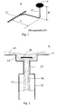
- Figure 1 shows schematically a known part of a siphonic drainage system. It includes a roof outlet 4 and pipes 23 connected to a horizontal collecting pipe 12, these pipes 23 are described as tailpipes 23.
- tailpipes 23 In the initial drainage process, correctly designed tailpipes 23 and their connected roof outlets 4 serve as small siphonic systems, capable of quickly filling up the collecting pipe 12 and downpipe (not shown) with rainwater. Hence, the total siphonic system will prime fast.
- a main object is consequently to solve the problem of reliably and more quickly prime a siphonic system.
- the invention stems from the insight that transitions in a siphonic system, such as vertical pipe work of different diameters or vertical pipe work with constrictions, may act as traps of a gas, such as air.
- a gas such as air.
- the entrapment of gas prevents siphonic action and prolongs the process of filling the system with liquid (priming).
- the invention provides an interface portion with an inner cross section area that increases continuously from the inlet end to the discharge end for a length of the interface portion that is at least 0.3 times the inner diameter of the discharge end. Due to this continuous increase during the specified length, gas is effectively prevented from being trapped downstream of the upstream portion. Thus, the interface portion of the invention promotes a faster priming of the siphonic system.
- a transition between the inlet end and the upstream portion is essentially in the form of a curve with a radius of at least 0.15 times the inner diameter of the discharge end.
- the liquid passing the transition can be made to more efficiently follow, at least partly, the interface portion.
- the patent US 5 522 197 describes a throttling device for a roof outlet of a siphonic drainage system, said system comprising multiple roof outlets joined to the same tube system. It solves the problem of providing separate roof outlet branches with correct flow resistances.
- the device consists of a deformable annular element that is arranged in an outlet passage and that can be deformed to a varying degree, in order to throttle the passage to a corresponding degree.
- a part of the throttling device may accidentally resemble the interface portion of the present application to the extent of having a portion with an inner cross section area that increases continuously.
- the length of the portion of the throttling device that has this increase is too short in order to attain the priming action of the interface portion of the present application and the transition radiuses are non-existent.
- the patent US 5 522 197 only address the problem of flow resistances and does not in any way, implicitly or explicitly, discuss the present problem of priming a siphonic system and there are no pointers to this problem or the solution according to the present invention at all.
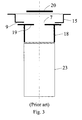
- Fig. 2 illustrates a cause to the problem of slow priming of certain siphonic systems.
- a siphonic drainage system 6 is shown.
- the system 6 includes a roof outlet 4, having an outlet spigot 13, and a tailpipe 23 of larger diameter than the outlet spigot 13.
- rainwater 14 is collected in the outlet bowl 15 of the roof outlet 4. The water flows down through the outlet spigot 13 and in to the tailpipe 23.
- the tailpipe 23 in this case has a larger diameter than the outlet spigot 13 and the connector connecting them has an abrupt change in diameter, the water forms a jet 16 that has a smaller diameter than the tailpipe 23. This leads to air 17 being trapped inside the tailpipe 23. Because of this air, the system will not work siphonically. Instead, the system works purely by gravity and therefore has a considerably lower water transport capacity. In order for the siphonic action to start, the tailpipe 23 must (gravitationally) be filled up with water up to the outlet spigot 13, evacuating all air. This filling will be slow and sometimes does not take place at all, even after a substantial time.
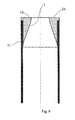
- a constricted connector 18 of prior art is shown in fig. 3. Its function is to connect a tailpipe 23 directly to an outlet bottom 9 of the drainage system, with no spigot in between.
- the constriction 19 is in this case necessary in order to adapt the opening 7 in the outlet bowl 15 to the air baffle 20. If the opening 7 becomes too large in respect of the size of the air baffle 20 above, the function of the baffle 20, to only allow water into the drainage system, may be compromised. This is due to that air may constantly be drawn into the pipe system at the side of the air baffle 20, and full bore flow will never be obtained at tolerable water depths on the roof.
- the tailpipes 23 in figures 6 and 8 if connected directly to the outlet bowl 15 or baseplate, would possibly create this situation.
- the constriction 19 in fig. 3 remedies this, but unfortunately, because of the abrupt transition from a small cross section area to a large cross section area, the problem described in the previous paragraph may occur.
- a new transition interface portion 1 design is suggested.
- a siphonic drainage system 6 is depicted in Figure 4.
- This siphonic drainage system includes a roof outlet 4, having an outlet spigot 13.
- the spigot 13 is connected to a connector 5, which in turn is connected to a tailpipe 23.
- the direction of water flowing is downwards in the figure; from the roof outlet 4 through the spigot 13, then through the connector 5 and in to the tailpipe 23.
- the inventive interface portion 1 is in this figure, as an example, contained in the connector 5.
- the siphonic system is said to have an upstream portion 2 and a downstream portion 3.
- the upstream portion 2 corresponds to the outlet spigot 13 and the downstream portion 3 corresponds to the lower part of the connector 5.
- the interface portion 1 extends between an inlet end 10 and a discharge end 11.
- the inlet end 10 is to be in connection with the upstream portion 2
- the discharge end 11 is to be in connection with the downstream portion 3.
- the interface portion 1 is arranged to bring, in use, the upstream portion 2 in liquid connection with the downstream portion 3.
- the inner cross section area of the interface portion 1 increases continuously from the inlet end 10 to the discharge end 11 for a length L of the interface portion 1 that is at least 0.3 times the inner diameter D of the discharge end 11 (see fig. 5).
- the interface portion counteracts an accumulation of a gas downstream of the upstream portion 2, that is in the interface portion 1 and downstream of the interface portion 1.
- the water instead of forming a jet as in fig. 2, at least partly follows the wall of the interface portion 1.
- the water may form a kind of a lid that traps the air in the interface portion 1 and/or the downstream portion 3 and pushes the air out of the system 6, thus facilitating priming of the system 6.
- the idea of the interface portion is to replace abrupt transition portions in siphonic systems.
- the interface portion enables at least some of the liquid in the siphonic system to follow the wall of the interface portion.
- abrupt portions which could be replaced by the interface portion, are a change from a small to a large diameter pipe or a constriction in a pipe, as exemplified above.
- a transition from the interface portion 1 to the upstream portion 2 and/or the downstream portion 3 of the siphonic system should preferably be smooth and could advantageously be essentially in the form of a curve with a radius R of at least 0.15 times the inner diameter D of the discharge end 11, see for instance fig. 5.
- the interface portion can be provided in several ways. For instance it can be provided as an integral part of a building block of a siphonic system, such as an integral part of a roof outlet, a pipe or a connector. In fig. 10, the interface portion 1 is provided as an integral part of a roof outlet 4. Examples of connectors are given in figs. 4 through 8. It could also be provided as a sleeve insert 24 for a building block of a siphonic system, such as a pipe. An example of such a sleeve insert 24, inserted into a pipe, is depicted in fig. 9. An example of an interface portion 1 integral with a pipe is given in fig. 11.
- connection to connect the building block, including the interface portion, to other building blocks of the siphonic system include threads 25, flanges 8 and other conventional connection means. Examples of threads 25 and flanges 8 can for instance be found in figs. 5 and 6. Connection by welding would of course also be possible.
- the upstream portion of the siphonic drainage system could be a part of a roof outlet, such as an outlet spigot 13 or an outlet bottom 9.
- a part could be studied in for example figs. 4 and 6.
- For an outlet bottom it is possible to adapt the inlet end either to be connected to the outside or to the inside of the outlet bottom.
- Such outlet bottoms 9 and inlet ends 10 are depicted in figs. 6 and 8.
- Figs. 7a and 7b are close-ups in different views of fig. 6.
- the discharge end 11 is similarly adapted to be connected to a downstream portion 3 being part of a tailpipe of a siphonic drainage system.
- the length L of the interface portion 1 should, as has been mentioned, be at least 0.3 times the inner diameter D of the discharge end 11 for a beneficial priming effect beginning to occur.
- An increase of said length L from between 0.3 to 0.5 times said inner diameter D yields an increased priming effect.
- an even stronger priming effect can be observed, if the length L of the interface portion 1 is at least 0.5 times the inner diameter D of the discharge end 11.
- the material in the building blocks containing the interface portions are chosen to match the material of other building blocks to which the interface portion building block is to be connected. For example, welding or solvent welding of plastic materials, mechanical couplings, or welding of steel and other metals may be used for achieving a connection.
- the wall of the interface portion 1 can be designed to be more or less smooth, the main requirement being that the water should be led to at least partly follow the same.
- cross sections of the pipe work of the siphonic systems are circular.
- Other cross sections such as for instance quadratic, rectangular or elliptic are also applicable.
- interface portion of the invention is particularly useful in siphonic roof drainage pipe systems, it may of course also be utilised in any siphonic pipe system where transitions between different diameters have to be performed.
Landscapes
- Engineering & Computer Science (AREA)
- Architecture (AREA)
- Civil Engineering (AREA)
- Structural Engineering (AREA)
- Jet Pumps And Other Pumps (AREA)
Priority Applications (1)
| Application Number | Priority Date | Filing Date | Title |
|---|---|---|---|
| PL07445022T PL1865121T3 (pl) | 2006-05-31 | 2007-05-11 | Syfonowy system odwadniający |
Applications Claiming Priority (1)
| Application Number | Priority Date | Filing Date | Title |
|---|---|---|---|
| SE0601202A SE529951C2 (sv) | 2006-05-31 | 2006-05-31 | Gränssnittsparti för ett sifoniskt system |
Publications (3)
| Publication Number | Publication Date |
|---|---|
| EP1865121A2 true EP1865121A2 (de) | 2007-12-12 |
| EP1865121A3 EP1865121A3 (de) | 2011-03-02 |
| EP1865121B1 EP1865121B1 (de) | 2013-10-02 |
Family
ID=38370388
Family Applications (1)
| Application Number | Title | Priority Date | Filing Date |
|---|---|---|---|
| EP07445022.2A Active EP1865121B1 (de) | 2006-05-31 | 2007-05-11 | Entwässerungsanlage mit Druckströmung |
Country Status (4)
| Country | Link |
|---|---|
| US (1) | US20070277447A1 (de) |
| EP (1) | EP1865121B1 (de) |
| PL (1) | PL1865121T3 (de) |
| SE (1) | SE529951C2 (de) |
Cited By (1)
| Publication number | Priority date | Publication date | Assignee | Title |
|---|---|---|---|---|
| BE1019528A5 (nl) * | 2010-10-05 | 2012-08-07 | Aquadraat Engineering Bvba | Dal en werkwijze voor het vervaardigen van een dal en hemelwaterafvoersysteem voorzien van zulke dal. |
Families Citing this family (4)
| Publication number | Priority date | Publication date | Assignee | Title |
|---|---|---|---|---|
| JP5828066B2 (ja) * | 2010-12-21 | 2015-12-02 | パナソニックIpマネジメント株式会社 | 雨樋構造 |
| FR3121461B1 (fr) * | 2021-04-06 | 2023-08-04 | Rikksen | Dispositif de drainage équipé d’un manchon de fixation pour construction, notamment un toit de bâtiment ou une terrasse |
| JP2023096781A (ja) * | 2021-12-27 | 2023-07-07 | パナソニックIpマネジメント株式会社 | 配管部材、及び、雨樋システム |
| JP2023109014A (ja) * | 2022-01-26 | 2023-08-07 | パナソニックIpマネジメント株式会社 | 配管部材、及び、雨樋システム |
Family Cites Families (19)
| Publication number | Priority date | Publication date | Assignee | Title |
|---|---|---|---|---|
| US925946A (en) * | 1909-06-22 | Soil-pipe flashing | ||
| US1756045A (en) * | 1926-12-04 | 1930-04-29 | Wilhelmi Valentin | Boiler connection |
| US2347044A (en) * | 1941-10-10 | 1944-04-18 | Joseph E Frances | Pipe bell hub and sealing means |
| US2322587A (en) * | 1942-07-21 | 1943-06-22 | Thomas F Payne | Pipe joint |
| US3727953A (en) * | 1969-02-05 | 1973-04-17 | Advanced Drainage Syst Inc | Tube coupling |
| DE2226508B2 (de) * | 1972-05-31 | 1978-08-03 | Karl 6460 Gelnhausen Kuhn | Schnellverbinder aus Elastomere, insbesondere zum Anschluß von Spülrohren von WC-Becken |
| US3909045A (en) * | 1974-10-10 | 1975-09-30 | Gen Electric | Tubing joint for adhesive bonding |
| US4120083A (en) * | 1976-12-06 | 1978-10-17 | Zap-Lok Systems International, Inc. | Method of pipe joining |
| EP0141675B1 (de) * | 1983-11-08 | 1988-05-04 | Raychem Limited | Vorrichtung und Verfahren zum Verbinden langgestreckter Gegenstände |
| DE4203329A1 (de) * | 1991-06-15 | 1993-08-12 | Krupp Vdm Gmbh | Gasdichte verbindung zwischen rohren kleinen durchmessers |
| SE469089B (sv) * | 1991-06-24 | 1993-05-10 | Stacke Metallarmatur Ab | Foerminskningsanordning foer roerkopplingar |
| FI88328C (fi) * | 1991-10-14 | 1993-04-26 | Megsent Insinoeoeritoimisto | Foerfarande vid en avvattningsanordning foer tak och en avvattningsanordning |
| US5211221A (en) * | 1991-11-26 | 1993-05-18 | Mccord Heat Transfer | Method and apparatus for joining coolant tubes of a heat exchanger |
| US5511831A (en) * | 1993-01-04 | 1996-04-30 | Modine Manufacturing Company | Self-centering, self-seating, double-sealing, interference fit tube joint |
| US6318397B1 (en) * | 1999-08-04 | 2001-11-20 | Donald G. Huber | Side port floor drain |
| US6548760B1 (en) * | 2000-12-11 | 2003-04-15 | Eastern Sheet Metal, Inc. | One-piece seamless reducer |
| EP1247910B1 (de) * | 2001-04-06 | 2009-04-08 | Geberit Technik Ag | Geruchsverschluss für ein wasserloses Urinal |
| CN2668972Y (zh) * | 2003-09-02 | 2005-01-05 | 上海中英阀门管件有限公司 | 异径接头 |
| TWM271973U (en) * | 2004-12-24 | 2005-08-01 | Ching-Wen Chen | Improved connection structure of a metal connector |
-
2006
- 2006-05-31 SE SE0601202A patent/SE529951C2/sv not_active IP Right Cessation
-
2007
- 2007-05-11 PL PL07445022T patent/PL1865121T3/pl unknown
- 2007-05-11 EP EP07445022.2A patent/EP1865121B1/de active Active
- 2007-05-30 US US11/806,220 patent/US20070277447A1/en not_active Abandoned
Cited By (1)
| Publication number | Priority date | Publication date | Assignee | Title |
|---|---|---|---|---|
| BE1019528A5 (nl) * | 2010-10-05 | 2012-08-07 | Aquadraat Engineering Bvba | Dal en werkwijze voor het vervaardigen van een dal en hemelwaterafvoersysteem voorzien van zulke dal. |
Also Published As
| Publication number | Publication date |
|---|---|
| EP1865121A3 (de) | 2011-03-02 |
| EP1865121B1 (de) | 2013-10-02 |
| PL1865121T3 (pl) | 2014-03-31 |
| US20070277447A1 (en) | 2007-12-06 |
| SE529951C2 (sv) | 2008-01-15 |
| SE0601202L (sv) | 2007-12-01 |
Similar Documents
| Publication | Publication Date | Title |
|---|---|---|
| EP1865121B1 (de) | Entwässerungsanlage mit Druckströmung | |
| DE60034462T2 (de) | Vorrichtung zur trennung eines fluids insbesondere in eine gas- und eine flüssigphase | |
| US8459698B2 (en) | Riser cap and irrigation piping system using same | |
| US20100244438A1 (en) | Barbed fitting for hose connection | |
| JP6835995B1 (ja) | 雨樋システム | |
| US8881803B1 (en) | Desander system | |
| CN111278525A (zh) | 过滤器组件的排水机构 | |
| CN209494001U (zh) | 排放物处理装置及用于处理排放物的系统 | |
| US8104496B1 (en) | Reverse flow back pressure pump | |
| CN210483671U (zh) | 多流道旁通筛管 | |
| JP6377895B2 (ja) | 配管ユニット及び配管施工方法 | |
| US20170356175A1 (en) | Drain unclogging system | |
| US2263588A (en) | Precast monolithic concrete culvert terminal | |
| US20130315668A1 (en) | Building drainage system pipes with improved performance at low flow | |
| CN114080328B (zh) | 用于不同密度的流体的分开排放的排放接头 | |
| US1596199A (en) | Down spout | |
| CN220978578U (zh) | 一种预制件钢筋连接装置 | |
| EP4628662A1 (de) | Fallrohr | |
| CN107906280A (zh) | 偏心补偿接头 | |
| CN208197144U (zh) | 一种预埋槽道可分离堵头 | |
| CN215803276U (zh) | 一种可封堵的装配式灌浆转接头 | |
| RU2163701C1 (ru) | Устройство для дозировки реагента в трубопровод | |
| JP2023012990A (ja) | 雨樋の接続構造 | |
| US8100176B2 (en) | Device for removing liquids from the well-bore of a gas producing well | |
| CN205676998U (zh) | 一种如厕洁具疏通器 |
Legal Events
| Date | Code | Title | Description |
|---|---|---|---|
| PUAI | Public reference made under article 153(3) epc to a published international application that has entered the european phase |
Free format text: ORIGINAL CODE: 0009012 |
|
| AK | Designated contracting states |
Kind code of ref document: A2 Designated state(s): AT BE BG CH CY CZ DE DK EE ES FI FR GB GR HU IE IS IT LI LT LU LV MC MT NL PL PT RO SE SI SK TR |
|
| AX | Request for extension of the european patent |
Extension state: AL BA HR MK YU |
|
| PUAL | Search report despatched |
Free format text: ORIGINAL CODE: 0009013 |
|
| AK | Designated contracting states |
Kind code of ref document: A3 Designated state(s): AT BE BG CH CY CZ DE DK EE ES FI FR GB GR HU IE IS IT LI LT LU LV MC MT NL PL PT RO SE SI SK TR |
|
| AX | Request for extension of the european patent |
Extension state: AL BA HR MK RS |
|
| 17P | Request for examination filed |
Effective date: 20110831 |
|
| AKX | Designation fees paid |
Designated state(s): AT BE BG CH CY CZ DE DK EE ES FI FR GB GR HU IE IS IT LI LT LU LV MC MT NL PL PT RO SE SI SK TR |
|
| 17Q | First examination report despatched |
Effective date: 20111109 |
|
| GRAP | Despatch of communication of intention to grant a patent |
Free format text: ORIGINAL CODE: EPIDOSNIGR1 |
|
| INTG | Intention to grant announced |
Effective date: 20130415 |
|
| GRAS | Grant fee paid |
Free format text: ORIGINAL CODE: EPIDOSNIGR3 |
|
| GRAA | (expected) grant |
Free format text: ORIGINAL CODE: 0009210 |
|
| AK | Designated contracting states |
Kind code of ref document: B1 Designated state(s): AT BE BG CH CY CZ DE DK EE ES FI FR GB GR HU IE IS IT LI LT LU LV MC MT NL PL PT RO SE SI SK TR |
|
| REG | Reference to a national code |
Ref country code: GB Ref legal event code: FG4D |
|
| REG | Reference to a national code |
Ref country code: CH Ref legal event code: EP Ref country code: AT Ref legal event code: REF Ref document number: 634710 Country of ref document: AT Kind code of ref document: T Effective date: 20131015 |
|
| 111L | Licence recorded |
Designated state(s): AT BE BG CH CY CZ DE DK EE ES FI FR GB GR HU IE IS IT LT LU LV MC MT NL PL PT RO SE SI SK TR Name of requester: UV-SYSTEM NORDIC AB, SE Effective date: 20130812 |
|
| REG | Reference to a national code |
Ref country code: IE Ref legal event code: FG4D |
|
| REG | Reference to a national code |
Ref country code: DE Ref legal event code: R096 Ref document number: 602007033109 Country of ref document: DE Effective date: 20131128 |
|
| REG | Reference to a national code |
Ref country code: NL Ref legal event code: T3 |
|
| REG | Reference to a national code |
Ref country code: SE Ref legal event code: TRGR |
|
| REG | Reference to a national code |
Ref country code: AT Ref legal event code: MK05 Ref document number: 634710 Country of ref document: AT Kind code of ref document: T Effective date: 20131002 |
|
| PG25 | Lapsed in a contracting state [announced via postgrant information from national office to epo] |
Ref country code: SI Free format text: LAPSE BECAUSE OF FAILURE TO SUBMIT A TRANSLATION OF THE DESCRIPTION OR TO PAY THE FEE WITHIN THE PRESCRIBED TIME-LIMIT Effective date: 20131002 |
|
| REG | Reference to a national code |
Ref country code: LT Ref legal event code: MG4D |
|
| PG25 | Lapsed in a contracting state [announced via postgrant information from national office to epo] |
Ref country code: IS Free format text: LAPSE BECAUSE OF FAILURE TO SUBMIT A TRANSLATION OF THE DESCRIPTION OR TO PAY THE FEE WITHIN THE PRESCRIBED TIME-LIMIT Effective date: 20140202 Ref country code: LT Free format text: LAPSE BECAUSE OF FAILURE TO SUBMIT A TRANSLATION OF THE DESCRIPTION OR TO PAY THE FEE WITHIN THE PRESCRIBED TIME-LIMIT Effective date: 20131002 Ref country code: FI Free format text: LAPSE BECAUSE OF FAILURE TO SUBMIT A TRANSLATION OF THE DESCRIPTION OR TO PAY THE FEE WITHIN THE PRESCRIBED TIME-LIMIT Effective date: 20131002 Ref country code: CZ Free format text: LAPSE BECAUSE OF FAILURE TO SUBMIT A TRANSLATION OF THE DESCRIPTION OR TO PAY THE FEE WITHIN THE PRESCRIBED TIME-LIMIT Effective date: 20131002 |
|
| PG25 | Lapsed in a contracting state [announced via postgrant information from national office to epo] |
Ref country code: LV Free format text: LAPSE BECAUSE OF FAILURE TO SUBMIT A TRANSLATION OF THE DESCRIPTION OR TO PAY THE FEE WITHIN THE PRESCRIBED TIME-LIMIT Effective date: 20131002 Ref country code: ES Free format text: LAPSE BECAUSE OF FAILURE TO SUBMIT A TRANSLATION OF THE DESCRIPTION OR TO PAY THE FEE WITHIN THE PRESCRIBED TIME-LIMIT Effective date: 20131002 Ref country code: AT Free format text: LAPSE BECAUSE OF FAILURE TO SUBMIT A TRANSLATION OF THE DESCRIPTION OR TO PAY THE FEE WITHIN THE PRESCRIBED TIME-LIMIT Effective date: 20131002 Ref country code: CY Free format text: LAPSE BECAUSE OF FAILURE TO SUBMIT A TRANSLATION OF THE DESCRIPTION OR TO PAY THE FEE WITHIN THE PRESCRIBED TIME-LIMIT Effective date: 20131002 |
|
| PG25 | Lapsed in a contracting state [announced via postgrant information from national office to epo] |
Ref country code: PT Free format text: LAPSE BECAUSE OF FAILURE TO SUBMIT A TRANSLATION OF THE DESCRIPTION OR TO PAY THE FEE WITHIN THE PRESCRIBED TIME-LIMIT Effective date: 20140203 |
|
| REG | Reference to a national code |
Ref country code: DE Ref legal event code: R097 Ref document number: 602007033109 Country of ref document: DE |
|
| PG25 | Lapsed in a contracting state [announced via postgrant information from national office to epo] |
Ref country code: EE Free format text: LAPSE BECAUSE OF FAILURE TO SUBMIT A TRANSLATION OF THE DESCRIPTION OR TO PAY THE FEE WITHIN THE PRESCRIBED TIME-LIMIT Effective date: 20131002 |
|
| PLBE | No opposition filed within time limit |
Free format text: ORIGINAL CODE: 0009261 |
|
| STAA | Information on the status of an ep patent application or granted ep patent |
Free format text: STATUS: NO OPPOSITION FILED WITHIN TIME LIMIT |
|
| PG25 | Lapsed in a contracting state [announced via postgrant information from national office to epo] |
Ref country code: IT Free format text: LAPSE BECAUSE OF FAILURE TO SUBMIT A TRANSLATION OF THE DESCRIPTION OR TO PAY THE FEE WITHIN THE PRESCRIBED TIME-LIMIT Effective date: 20131002 Ref country code: RO Free format text: LAPSE BECAUSE OF FAILURE TO SUBMIT A TRANSLATION OF THE DESCRIPTION OR TO PAY THE FEE WITHIN THE PRESCRIBED TIME-LIMIT Effective date: 20131002 Ref country code: SK Free format text: LAPSE BECAUSE OF FAILURE TO SUBMIT A TRANSLATION OF THE DESCRIPTION OR TO PAY THE FEE WITHIN THE PRESCRIBED TIME-LIMIT Effective date: 20131002 |
|
| 26N | No opposition filed |
Effective date: 20140703 |
|
| PG25 | Lapsed in a contracting state [announced via postgrant information from national office to epo] |
Ref country code: DK Free format text: LAPSE BECAUSE OF FAILURE TO SUBMIT A TRANSLATION OF THE DESCRIPTION OR TO PAY THE FEE WITHIN THE PRESCRIBED TIME-LIMIT Effective date: 20131002 |
|
| REG | Reference to a national code |
Ref country code: DE Ref legal event code: R097 Ref document number: 602007033109 Country of ref document: DE Effective date: 20140703 |
|
| PG25 | Lapsed in a contracting state [announced via postgrant information from national office to epo] |
Ref country code: LU Free format text: LAPSE BECAUSE OF FAILURE TO SUBMIT A TRANSLATION OF THE DESCRIPTION OR TO PAY THE FEE WITHIN THE PRESCRIBED TIME-LIMIT Effective date: 20140511 |
|
| REG | Reference to a national code |
Ref country code: CH Ref legal event code: PL |
|
| PG25 | Lapsed in a contracting state [announced via postgrant information from national office to epo] |
Ref country code: MC Free format text: LAPSE BECAUSE OF FAILURE TO SUBMIT A TRANSLATION OF THE DESCRIPTION OR TO PAY THE FEE WITHIN THE PRESCRIBED TIME-LIMIT Effective date: 20131002 Ref country code: LI Free format text: LAPSE BECAUSE OF NON-PAYMENT OF DUE FEES Effective date: 20140531 Ref country code: CH Free format text: LAPSE BECAUSE OF NON-PAYMENT OF DUE FEES Effective date: 20140531 |
|
| REG | Reference to a national code |
Ref country code: IE Ref legal event code: MM4A |
|
| PG25 | Lapsed in a contracting state [announced via postgrant information from national office to epo] |
Ref country code: IE Free format text: LAPSE BECAUSE OF NON-PAYMENT OF DUE FEES Effective date: 20140511 |
|
| PG25 | Lapsed in a contracting state [announced via postgrant information from national office to epo] |
Ref country code: MT Free format text: LAPSE BECAUSE OF FAILURE TO SUBMIT A TRANSLATION OF THE DESCRIPTION OR TO PAY THE FEE WITHIN THE PRESCRIBED TIME-LIMIT Effective date: 20131002 |
|
| REG | Reference to a national code |
Ref country code: FR Ref legal event code: PLFP Year of fee payment: 10 |
|
| PG25 | Lapsed in a contracting state [announced via postgrant information from national office to epo] |
Ref country code: BG Free format text: LAPSE BECAUSE OF FAILURE TO SUBMIT A TRANSLATION OF THE DESCRIPTION OR TO PAY THE FEE WITHIN THE PRESCRIBED TIME-LIMIT Effective date: 20131002 |
|
| PG25 | Lapsed in a contracting state [announced via postgrant information from national office to epo] |
Ref country code: GR Free format text: LAPSE BECAUSE OF FAILURE TO SUBMIT A TRANSLATION OF THE DESCRIPTION OR TO PAY THE FEE WITHIN THE PRESCRIBED TIME-LIMIT Effective date: 20140103 |
|
| PG25 | Lapsed in a contracting state [announced via postgrant information from national office to epo] |
Ref country code: TR Free format text: LAPSE BECAUSE OF FAILURE TO SUBMIT A TRANSLATION OF THE DESCRIPTION OR TO PAY THE FEE WITHIN THE PRESCRIBED TIME-LIMIT Effective date: 20131002 Ref country code: HU Free format text: LAPSE BECAUSE OF FAILURE TO SUBMIT A TRANSLATION OF THE DESCRIPTION OR TO PAY THE FEE WITHIN THE PRESCRIBED TIME-LIMIT; INVALID AB INITIO Effective date: 20070511 |
|
| REG | Reference to a national code |
Ref country code: FR Ref legal event code: PLFP Year of fee payment: 11 |
|
| REG | Reference to a national code |
Ref country code: FR Ref legal event code: PLFP Year of fee payment: 12 |
|
| PGFP | Annual fee paid to national office [announced via postgrant information from national office to epo] |
Ref country code: DE Payment date: 20220531 Year of fee payment: 16 |
|
| P01 | Opt-out of the competence of the unified patent court (upc) registered |
Effective date: 20230519 |
|
| REG | Reference to a national code |
Ref country code: DE Ref legal event code: R119 Ref document number: 602007033109 Country of ref document: DE |
|
| PG25 | Lapsed in a contracting state [announced via postgrant information from national office to epo] |
Ref country code: DE Free format text: LAPSE BECAUSE OF NON-PAYMENT OF DUE FEES Effective date: 20231201 |
|
| PGFP | Annual fee paid to national office [announced via postgrant information from national office to epo] |
Ref country code: PL Payment date: 20250429 Year of fee payment: 19 |
|
| PGFP | Annual fee paid to national office [announced via postgrant information from national office to epo] |
Ref country code: GB Payment date: 20250527 Year of fee payment: 19 |
|
| PGFP | Annual fee paid to national office [announced via postgrant information from national office to epo] |
Ref country code: NL Payment date: 20250528 Year of fee payment: 19 Ref country code: BE Payment date: 20250528 Year of fee payment: 19 |
|
| PGFP | Annual fee paid to national office [announced via postgrant information from national office to epo] |
Ref country code: FR Payment date: 20250527 Year of fee payment: 19 |
|
| PGFP | Annual fee paid to national office [announced via postgrant information from national office to epo] |
Ref country code: SE Payment date: 20250527 Year of fee payment: 19 |