EP1862684A1 - Spline connector - Google Patents
Spline connector Download PDFInfo
- Publication number
- EP1862684A1 EP1862684A1 EP07010573A EP07010573A EP1862684A1 EP 1862684 A1 EP1862684 A1 EP 1862684A1 EP 07010573 A EP07010573 A EP 07010573A EP 07010573 A EP07010573 A EP 07010573A EP 1862684 A1 EP1862684 A1 EP 1862684A1
- Authority
- EP
- European Patent Office
- Prior art keywords
- connector
- spring
- spline
- members
- teeth
- Prior art date
- Legal status (The legal status is an assumption and is not a legal conclusion. Google has not performed a legal analysis and makes no representation as to the accuracy of the status listed.)
- Granted
Links
- 230000013011 mating Effects 0.000 claims description 4
- 238000000926 separation method Methods 0.000 abstract 1
- 230000005540 biological transmission Effects 0.000 description 12
- 230000010355 oscillation Effects 0.000 description 5
- 230000001133 acceleration Effects 0.000 description 1
- 238000006243 chemical reaction Methods 0.000 description 1
- 230000008878 coupling Effects 0.000 description 1
- 238000010168 coupling process Methods 0.000 description 1
- 238000005859 coupling reaction Methods 0.000 description 1
- 230000000694 effects Effects 0.000 description 1
- 238000000034 method Methods 0.000 description 1
- 230000036316 preload Effects 0.000 description 1
- 238000010561 standard procedure Methods 0.000 description 1
Images





Classifications
-
- F—MECHANICAL ENGINEERING; LIGHTING; HEATING; WEAPONS; BLASTING
- F16—ENGINEERING ELEMENTS AND UNITS; GENERAL MEASURES FOR PRODUCING AND MAINTAINING EFFECTIVE FUNCTIONING OF MACHINES OR INSTALLATIONS; THERMAL INSULATION IN GENERAL
- F16D—COUPLINGS FOR TRANSMITTING ROTATION; CLUTCHES; BRAKES
- F16D3/00—Yielding couplings, i.e. with means permitting movement between the connected parts during the drive
- F16D3/50—Yielding couplings, i.e. with means permitting movement between the connected parts during the drive with the coupling parts connected by one or more intermediate members
- F16D3/64—Yielding couplings, i.e. with means permitting movement between the connected parts during the drive with the coupling parts connected by one or more intermediate members comprising elastic elements arranged between substantially-radial walls of both coupling parts
- F16D3/66—Yielding couplings, i.e. with means permitting movement between the connected parts during the drive with the coupling parts connected by one or more intermediate members comprising elastic elements arranged between substantially-radial walls of both coupling parts the elements being metallic, e.g. in the form of coils
-
- F—MECHANICAL ENGINEERING; LIGHTING; HEATING; WEAPONS; BLASTING
- F16—ENGINEERING ELEMENTS AND UNITS; GENERAL MEASURES FOR PRODUCING AND MAINTAINING EFFECTIVE FUNCTIONING OF MACHINES OR INSTALLATIONS; THERMAL INSULATION IN GENERAL
- F16D—COUPLINGS FOR TRANSMITTING ROTATION; CLUTCHES; BRAKES
- F16D1/00—Couplings for rigidly connecting two coaxial shafts or other movable machine elements
- F16D1/10—Quick-acting couplings in which the parts are connected by simply bringing them together axially
- F16D2001/103—Quick-acting couplings in which the parts are connected by simply bringing them together axially the torque is transmitted via splined connections
Definitions
- the present invention relates to spline type torsional connectors between driving and driven members.
- Spline connectors are typically used to transmit torque from a driving member to a concentric driven member.
- a spline connector typically will have small torsional force exchange members referred to as teeth or larger torsional force exchange members referred to as lugs. It is common to refer to both types of torsional force exchange members as "spline teeth”.
- Automotive vehicles typically have a spline connector between an output shaft of an engine and an input shaft to a transmission. During startup and shutdown of the engine, torsional vibrations of the engine can cause the spline connector to oscillate, contacting the front and back of the spline teeth in an alternating fashion. In effect, the torque from the engine output becomes negative for a brief instant.
- the present invention provides a spline connector for a torsionally connected driving and driven machine.
- the spline connector includes driving and driven members.
- Backlash exists between teeth of the spline connector driving and driven members.
- a spring biases the teeth of the spline connector driving and driven members to engage with one another in a direction of contact to counteract negative torque of the driving member.
- the present invention can be used with or without a conventional damper.
- Figure 1 A is a schematic view of a spline connector
- Figure 1B is a schematic view of a spline connector, according to the present invention.
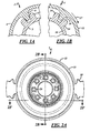
- Figure 2A is a front plan view of a spline connector, according to the present invention.
- Figure 2B is a sectional view taken along line 2B-2B of Figure 2A;
- Figure 2C is a front plan view of a female portion of the spline connector shown in Figure 2A;
- Figure 2D is a sectional view taken along line 2D-2D of Figure 2C;
- Figure 2E is a perspective view of the female portion of the spline connector shown in Figure 2C;
- Figure 2F is a sectional view taken along lines 2F-2F of Figure 2A;
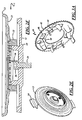
- Figure 2G is an enlarged view of a portion of the spline connector shown in Figure 2B additionally illustrating portions of the operating environment of the connector;
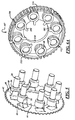
- Figure 3A is a perspective view of the spring plate utilized in the spline connector shown in Figure 2A;
- Figure 3B is a top plan view of the spring plate shown in Figure 3A;
- Figure 3C is a side elevational view of the spring plate shown in Figure 3A;
- Figure 4 is a perspective view of portions of the spline connector shown in Figure 2A looking towards a male member engine side of the connector with major portions of the female member (transmission side) of the connector being removed for clarity of illustration;
- Figure 5 is a perspective view illustrating placement of the spring plate upon the bolt heads of the male member of the connector with other portions of the male and female members being removed for clarity of illustration;
- Figure 6A is a partial perspective view of an alternative embodiment spline connector of the present invention with portions of the male and female members of the connector being removed for clarity of illustration;
- Figure 6B is a rear plan view of the connector of Figure 6a;
- Figure 6C is a sectional view of the connector shown in Figure 6B with portions of the connector being removed for clarity of illustration;
- Figure 7 is a view similar to that of Figure 6 with portions of the spline connector being removed for clarity of illustration, illustrating placement of an adapter plate upon the male member of the coupler;
- Figure 8A is a schematic sectional view of yet another embodiment of a spline connector according to the present invention.
- Figure 8B is a schematic sectional view of a portion of the spline connector shown in Figure 8A with the connector members being mated;
- Figure 8C is a schematic operational view of a portion of the spline connector shown in Figure 8A in a position subsequent to that of Figure 8B;
- Figure 8D is a schematic operational view of a portion of the spline connector shown in Figure 8A wherein the engine and transmission are fully mated;
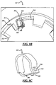
- Figure 9A is a front plan view of yet another spline connector embodiment of the present invention.
- Figure 9B is an enlargement of a portion of Figure 9A.
- Figure 9C is an enlargement of a spring utilized in the spline connector shown in Figure 9A.
- Figure 1 A illustrates a spline type coupling or connector 2 having a male spline connector member 3 as a driving member and a female spline connector member 4 as a driven member.
- the male member can be the driven member.
- the male member 3 can be integral with a fly wheel.
- the male member 3 has torsional force transmission members provided by spline teeth 5 (only two teeth shown) and the female spline connector member 4 has spline teeth 6 (only one tooth shown). Between the teeth 5, 6 there exists a slight clearance or gap commonly referred to as backlash 9 to ease assembly. Negative torque oscillations due to the reciprocal nature of the engine can cause the teeth 5, 6 to move back and forth with respect to each other contacting and causing noise.
- Figure 1 B illustrates the spline connector 7 of the present invention with a spring (not shown in Figure 1B) providing a biasing force forcing engagement between a male tooth 14 with a female tooth 16 under momentary negative torque conditions.
- the spring preloads the tooth 14 to contact the tooth 16 in the direction of rotation 17.
- male member 10 is integrated with a fly wheel 11.
- the male member 10 is connected by a series of bolts 24 having heads 26 with a power source machine such as a motor or engine having an output shaft 28.
- a female member 12 is formed as a cylindrical drum with the spline teeth 16 being along its inner surface.
- the female member cylindrical drum 12 is welded to a plate 23 of a damper 13.
- the plate 23 is torsionally connected with a clutch housing (not shown) by tabs 30.
- the clutch housing is torsionally connected with inner and outer input shafts (not shown) of a transmission by splined hubs 20 and 22 ( Figure 2G).
- the spline connector 7 also includes a spring plate 40.
- the spring plate 40 on its outer diameter has a plurality of spline teeth 42.
- the spline teeth 42 provide for the torsional connection of the spring plate 40 with the female member 12.
- the spring plate 40 also has a central opening 44. Central opening 44 is fitted over a central hub 46 that is connected with the female member 12.
- the spring plate 40 has a plurality of cut-outs 48. Formed from the cut-outs 48 are a plurality of spring fingers or tabs 50.
- the spring tabs 50 have a contour 52 to allow the tabs to partially encircle the bolt heads 26.
- the spring tabs 50 are also in a circumferential direction having a tapered surface 54.
- the male and female members 10, 12 are not axially connected together.
- the locations of the male and female members 10, 12 are established by the axial location of the engine and transmission which is further established by the connection of the engine and transmission casings together.
- the mating of the transmission to the engine will cause the bolt heads 26 to engage the spring tabs 50 along the tapered surface 54 and thereby bias the bolt heads 26 in the direction 17 of rotation of the spline connector 7.
- the spring plate 40 further has a locating tab 56.
- the locating tab 56 extends along a flattened slot 58 provided between an interface of the male member 10 and female member 12. The locating tab 56 ensures that the spring tabs 50 are in the proper position upon assembly or mating of the transmission with the engine.
- the spring tab 50 pushes against the bolt heads 26 causing the female member 12 to react in a direction opposite of that of rotation 17.
- the above noted reaction causes the teeth 16 to be brought into engagement with the teeth 14.
- the biasing force of the spring tabs 50 urge the teeth 16 in a direction of contact to counteract possible negative torque.
- FIG. 6A a radially inner portion of the male connector 110 is partially shown with the fly wheel removed for clarity of the illustration.
- the male connector 110 is connected to the engine output shaft by a series of bolts having bolt heads 26 as previously explained.
- the male connector 110 has a series of slots 112 in the cylinder which provides the male teeth 116.
- a plurality of coil springs 102 are mounted on the bolt heads 26.
- the springs 102 have legs 104, 106.
- the coil springs encircle the bolt heads 26 and are carried by the male member 110.
- the legs 106 are axially closest to the engine output shaft end extend through the slots 112.
- Figure 7 illustrates a portion of an adapter plate 108.
- the adapter plate 108 is joined to the female member (not shown) by fasteners or a spline connection in a manner as previously explained regarding spring plate 40.
- the adapter plate 108 has a series of ramps 120 for engagement with the legs 106 of the spring 102. As the transmission and engine are mated, the ramps 120 push against the spring legs 104, torquing the springs 102 and causing the spring leg 106 to present a biasing force against the teeth 116 male member 110.
- Figures 8A-8D ( Figure 8A being a partially sectioned view) provide a connector 207 having a U shaped flat plate spring 202 captured between two axially extending spline lugs 204,206 of the driving and driven members 208,210.
- a pin 212 holds the spring 202 in a retracted or precompressed condition until the engine and transmission mate the connector 207.
- Upon mating the lug 204 knocks the pin 212 into an aperture 214 partially releasing the spring 202.
- the lug 204 has an extension 216 that radially retains the spring 202 in location.
- Figures 9A-9C provide a spline connector 307 with a self-releasing looped U shaped spring 302.
- the spring is fitted over a special lug 304.
- the spring 302 has an end with a clip 306 having a hook 308.
- the hook is fitted within a window 310 of a leg 312 of the spring.
- Assembly of the driving and driven members 312,314 together causes the hook 308 to be knocked out of the window 310 thereby releasing the biasing force of the spring 302 which is captured between the lugs 316,318 of the driving and driven members.
Landscapes
- Engineering & Computer Science (AREA)
- General Engineering & Computer Science (AREA)
- Mechanical Engineering (AREA)
- Mechanical Operated Clutches (AREA)
Abstract
Description
- The present invention relates to spline type torsional connectors between driving and driven members.
- Spline connectors are typically used to transmit torque from a driving member to a concentric driven member. A spline connector typically will have small torsional force exchange members referred to as teeth or larger torsional force exchange members referred to as lugs. It is common to refer to both types of torsional force exchange members as "spline teeth". Automotive vehicles typically have a spline connector between an output shaft of an engine and an input shaft to a transmission. During startup and shutdown of the engine, torsional vibrations of the engine can cause the spline connector to oscillate, contacting the front and back of the spline teeth in an alternating fashion. In effect, the torque from the engine output becomes negative for a brief instant. This speed and acceleration as to which the oscillation occurs causes impact on the back and front side of the spline teeth causing noise. The reason the impact happens is due to the backlash in the spline teeth design. The spline teeth can be made with no backlash, however it would mean great difficulty in assembling and disassembling the connection. The standard method to fix the oscillation problem is to put a damper between the engine output and the spline input to the transmission. The damper then reduces the amplitude of the negative torque on the spline connector. It is desirable to provide a method and apparatus to further minimize oscillations resulting from negative torque on a spline connector.
- To meet the above noted desire of further minimizing oscillations resulting from negative torque in conjunction with a spline connector, the present invention is brought forth. The present invention provides a spline connector for a torsionally connected driving and driven machine. The spline connector includes driving and driven members. Backlash exists between teeth of the spline connector driving and driven members. A spring biases the teeth of the spline connector driving and driven members to engage with one another in a direction of contact to counteract negative torque of the driving member. The present invention can be used with or without a conventional damper.
- Further areas of applicability of the present invention will become apparent from the detailed description provided hereinafter. It should be understood that the detailed description and specific examples, while indicating the preferred embodiment of the invention, are intended for purposes of illustration only and are not intended to limit the scope of the invention.
- The present invention will become more fully understood from the detailed description and the accompanying drawings, wherein:
- Figure 1 A is a schematic view of a spline connector;
- Figure 1B is a schematic view of a spline connector, according to the present invention;
- Figure 2A is a front plan view of a spline connector, according to the present invention;
- Figure 2B is a sectional view taken along
line 2B-2B of Figure 2A; - Figure 2C is a front plan view of a female portion of the spline connector shown in Figure 2A;
- Figure 2D is a sectional view taken along
line 2D-2D of Figure 2C; - Figure 2E is a perspective view of the female portion of the spline connector shown in Figure 2C;
- Figure 2F is a sectional view taken along
lines 2F-2F of Figure 2A; - Figure 2G is an enlarged view of a portion of the spline connector shown in Figure 2B additionally illustrating portions of the operating environment of the connector;
- Figure 3A is a perspective view of the spring plate utilized in the spline connector shown in Figure 2A;
- Figure 3B is a top plan view of the spring plate shown in Figure 3A;
- Figure 3C is a side elevational view of the spring plate shown in Figure 3A;
- Figure 4 is a perspective view of portions of the spline connector shown in Figure 2A looking towards a male member engine side of the connector with major portions of the female member (transmission side) of the connector being removed for clarity of illustration;
- Figure 5 is a perspective view illustrating placement of the spring plate upon the bolt heads of the male member of the connector with other portions of the male and female members being removed for clarity of illustration;
- Figure 6A is a partial perspective view of an alternative embodiment spline connector of the present invention with portions of the male and female members of the connector being removed for clarity of illustration;
- Figure 6B is a rear plan view of the connector of Figure 6a;
- Figure 6C is a sectional view of the connector shown in Figure 6B with portions of the connector being removed for clarity of illustration;
- Figure 7 is a view similar to that of Figure 6 with portions of the spline connector being removed for clarity of illustration, illustrating placement of an adapter plate upon the male member of the coupler;
- Figure 8A is a schematic sectional view of yet another embodiment of a spline connector according to the present invention;
- Figure 8B is a schematic sectional view of a portion of the spline connector shown in Figure 8A with the connector members being mated;
- Figure 8C is a schematic operational view of a portion of the spline connector shown in Figure 8A in a position subsequent to that of Figure 8B;
- Figure 8D is a schematic operational view of a portion of the spline connector shown in Figure 8A wherein the engine and transmission are fully mated;
- Figure 9A is a front plan view of yet another spline connector embodiment of the present invention;
- Figure 9B is an enlargement of a portion of Figure 9A; and
- Figure 9C is an enlargement of a spring utilized in the spline connector shown in Figure 9A.
- The following description of the preferred embodiment(s) is merely exemplary in nature and is in no way intended to limit the invention, its application, or uses.
- Figure 1 A illustrates a spline type coupling or connector 2 having a male
spline connector member 3 as a driving member and a female spline connector member 4 as a driven member. In an alternate spline connector application (not shown), the male member can be the driven member. In many applications themale member 3 can be integral with a fly wheel. Themale member 3 has torsional force transmission members provided by spline teeth 5 (only two teeth shown) and the female spline connector member 4 has spline teeth 6 (only one tooth shown). Between theteeth 5, 6 there exists a slight clearance or gap commonly referred to as backlash 9 to ease assembly. Negative torque oscillations due to the reciprocal nature of the engine can cause theteeth 5, 6 to move back and forth with respect to each other contacting and causing noise. - Figure 1 B illustrates the spline connector 7 of the present invention with a spring (not shown in Figure 1B) providing a biasing force forcing engagement between a
male tooth 14 with afemale tooth 16 under momentary negative torque conditions. The spring preloads thetooth 14 to contact thetooth 16 in the direction of rotation 17. Referring additionally to Figures 2A-5,male member 10 is integrated with afly wheel 11. Themale member 10 is connected by a series ofbolts 24 havingheads 26 with a power source machine such as a motor or engine having anoutput shaft 28. Afemale member 12 is formed as a cylindrical drum with thespline teeth 16 being along its inner surface. The female membercylindrical drum 12 is welded to aplate 23 of adamper 13. In the example shown, theplate 23 is torsionally connected with a clutch housing (not shown) bytabs 30. The clutch housing is torsionally connected with inner and outer input shafts (not shown) of a transmission bysplined hubs 20 and 22 (Figure 2G). - The spline connector 7 also includes a
spring plate 40. Thespring plate 40 on its outer diameter has a plurality ofspline teeth 42. Thespline teeth 42 provide for the torsional connection of thespring plate 40 with thefemale member 12. Thespring plate 40 also has acentral opening 44.Central opening 44 is fitted over acentral hub 46 that is connected with thefemale member 12. Thespring plate 40 has a plurality of cut-outs 48. Formed from the cut-outs 48 are a plurality of spring fingers ortabs 50. Thespring tabs 50 have acontour 52 to allow the tabs to partially encircle the bolt heads 26. Thespring tabs 50 are also in a circumferential direction having a taperedsurface 54. Typically, the male andfemale members female members spring tabs 50 along the taperedsurface 54 and thereby bias the bolt heads 26 in the direction 17 of rotation of the spline connector 7. Thespring plate 40 further has a locatingtab 56. The locatingtab 56 extends along a flattenedslot 58 provided between an interface of themale member 10 andfemale member 12. The locatingtab 56 ensures that thespring tabs 50 are in the proper position upon assembly or mating of the transmission with the engine. In operation thespring tab 50 pushes against the bolt heads 26 causing thefemale member 12 to react in a direction opposite of that of rotation 17. The above noted reaction causes theteeth 16 to be brought into engagement with theteeth 14. The biasing force of thespring tabs 50 urge theteeth 16 in a direction of contact to counteract possible negative torque. - Referring additionally to Figures 6A-7, an alternate embodiment spline
torsional connector 107 of the present invention is provided. In Figure 6A a radially inner portion of themale connector 110 is partially shown with the fly wheel removed for clarity of the illustration. Themale connector 110 is connected to the engine output shaft by a series of bolts having bolt heads 26 as previously explained. Themale connector 110 has a series ofslots 112 in the cylinder which provides themale teeth 116. A plurality ofcoil springs 102 are mounted on the bolt heads 26. Thesprings 102 havelegs male member 110. Thelegs 106 are axially closest to the engine output shaft end extend through theslots 112. - Figure 7 illustrates a portion of an
adapter plate 108. Theadapter plate 108 is joined to the female member (not shown) by fasteners or a spline connection in a manner as previously explained regardingspring plate 40. Theadapter plate 108 has a series oframps 120 for engagement with thelegs 106 of thespring 102. As the transmission and engine are mated, theramps 120 push against thespring legs 104, torquing thesprings 102 and causing thespring leg 106 to present a biasing force against theteeth 116male member 110. - Figures 8A-8D (Figure 8A being a partially sectioned view) provide a
connector 207 having a U shapedflat plate spring 202 captured between two axially extending spline lugs 204,206 of the driving and driven members 208,210. Apin 212 holds thespring 202 in a retracted or precompressed condition until the engine and transmission mate theconnector 207. Upon mating thelug 204 knocks thepin 212 into anaperture 214 partially releasing thespring 202. Thelug 204 has anextension 216 that radially retains thespring 202 in location. - Figures 9A-9C provide a
spline connector 307 with a self-releasing looped U shapedspring 302. The spring is fitted over aspecial lug 304. Thespring 302 has an end with aclip 306 having ahook 308. Before assembly of theconnection 307 the hook is fitted within awindow 310 of aleg 312 of the spring. Assembly of the driving and driven members 312,314 together causes thehook 308 to be knocked out of thewindow 310 thereby releasing the biasing force of thespring 302 which is captured between the lugs 316,318 of the driving and driven members. - The description of the invention is merely exemplary in nature and, thus, variations that do not depart from the gist of the invention are intended to be within the scope of the invention. Such variations are not to be regarded as a departure from the spirit and scope of the invention.
Claims (16)
- A torsional force connector (7, 107, 207, 307) to torsionally connect a power source machine and power driven machine comprising:a driving connector member (10);a driven connector member (12) having backlash between teeth (14, 16) of said connector members; anda spring (50, 102, 202, 302) biasing said teeth (14, 16) of said connector members to engage with one another in a direction of contact to counteract negative torque of said driven connector member 10.
- A connector (7, 107, 207) as described in claim 1 wherein there are a plurality of springs (50, 102, 202, 302),
- A connector (7) as described in claim 1 wherein there is no axial connection between said connection members (10, 12).
- A connector (7) as described in claim 1 wherein at least one of said connection members (10) is torsionally held to one of said machines with bolts (24) and said spring (50) engages at least one of said bolts (24).
- A connector (7) as described in claim 4 wherein said spring (50) is connected with a plate (40).
- A connector (7) as described in claim 4 wherein said spring (50) is formed by a cut out (48) of said plate (40).
- A connector (7) as described in claim 1 wherein said spring (50) is connected with a plate (40) and said plate is connected by a spline connection with one of said connection members.
- A connector (207, 307) as described in claim 1 wherein said spring is captured between axially extending teeth of said connection members.
- A connector (107) as described in claim 1 wherein said spring (202) is a coil spring.
- A connector (107) as described in claim 1 wherein said spring (102) is a coil spring with a leg (104) engaged against a ramp (120) connected on one of said connection members.
- A connector (107) as described in claim 10 wherein said ramp (120) is provided by an adapter plate (108).
- A connector (207, 307) as described in claim 1 wherein said spring (202, 302) is compressed before assembly of said connector and mating of said spline connector members (2, 10, 208) (3, 4, 312) together causes said spring (202, 302) to be at least partially released.
- A connector (207) as described in claim 12 wherein said spring (202) is released by movement of a pin (212).
- A connector (207, 307) as described in claim 12 having a spring (302, 202) that self releases upon assembly of said spline connector.
- A connector (307) as described in claim 14 wherein said spring has hook (308) and window (310) ends.
- A connector (7, 107, 207, 307) as described in claim 1 wherein said driven member is fixably connected with a damper.
Applications Claiming Priority (2)
| Application Number | Priority Date | Filing Date | Title |
|---|---|---|---|
| US80978106P | 2006-05-30 | 2006-05-30 | |
| US11/805,730 US7534171B2 (en) | 2006-05-30 | 2007-05-24 | Spline connector |
Publications (2)
| Publication Number | Publication Date |
|---|---|
| EP1862684A1 true EP1862684A1 (en) | 2007-12-05 |
| EP1862684B1 EP1862684B1 (en) | 2010-06-23 |
Family
ID=38476153
Family Applications (1)
| Application Number | Title | Priority Date | Filing Date |
|---|---|---|---|
| EP07010573A Ceased EP1862684B1 (en) | 2006-05-30 | 2007-05-29 | Spline connector |
Country Status (3)
| Country | Link |
|---|---|
| US (1) | US7534171B2 (en) |
| EP (1) | EP1862684B1 (en) |
| DE (1) | DE602007007258D1 (en) |
Cited By (1)
| Publication number | Priority date | Publication date | Assignee | Title |
|---|---|---|---|---|
| WO2013023636A1 (en) * | 2011-08-17 | 2013-02-21 | Schaeffler Technologies AG & Co. KG | Dog clutch |
Families Citing this family (4)
| Publication number | Priority date | Publication date | Assignee | Title |
|---|---|---|---|---|
| US8376649B2 (en) * | 2005-10-17 | 2013-02-19 | Borgwarner Inc. | Coupling device for transmitting a torque |
| GB2490114B (en) * | 2011-04-18 | 2013-06-12 | Rolls Royce Plc | Rotational assembly |
| US11009119B2 (en) * | 2019-02-13 | 2021-05-18 | Ford Global Technologies, Llc | Electric machine and method for manufacture of an electric machine |
| DE102020105255B4 (en) * | 2020-02-28 | 2022-01-05 | Schaeffler Technologies AG & Co. KG | Rotary damper device |
Citations (8)
| Publication number | Priority date | Publication date | Assignee | Title |
|---|---|---|---|---|
| BE535319A (en) | ||||
| GB159580A (en) * | 1919-11-27 | 1921-02-28 | Henry Lewis Guy | Improvements in or relating to geared turbine installations |
| GB307921A (en) * | 1928-03-17 | 1929-10-31 | Tacke Maschinenfabrik Komm Ges | Improvements in or relating to resilient gear wheels |
| FR878126A (en) * | 1940-03-13 | 1943-01-12 | Automobili Isotta Fraschini Fa | Variable reduced length elastic seal for combustion engines |
| DE869139C (en) | 1944-03-31 | 1953-03-02 | Schweizerische Lokomotiv | Elastic shaft coupling, especially for toothed wheels with individual drives in rail vehicles |
| DE1267480B (en) * | 1962-03-26 | 1968-05-02 | Theo Burdelski | Elastic tooth coupling |
| US5564981A (en) * | 1994-02-10 | 1996-10-15 | Fukoku Co., Ltd. | Rotation transmission buffer apparatus |
| US20050192103A1 (en) * | 2002-03-26 | 2005-09-01 | Hauck Anthony L. | Flexible couplings |
Family Cites Families (13)
| Publication number | Priority date | Publication date | Assignee | Title |
|---|---|---|---|---|
| GB276000A (en) | 1926-08-12 | 1928-05-31 | Hans Hoffmann | Process and shaft for the reception and securing of driving mechanism |
| US1803995A (en) | 1930-05-15 | 1931-05-05 | Wright Aeronautical Corp | Splined connection |
| US2413810A (en) * | 1941-02-14 | 1947-01-07 | Borg Warner | Friction clutch |
| US2625415A (en) | 1950-04-29 | 1953-01-13 | Maytag Co | Flexible splined connection |
| US4875796A (en) | 1987-11-23 | 1989-10-24 | Eaton Corporation | Press-fit splined connection |
| JP3341961B2 (en) | 1994-02-28 | 2002-11-05 | 株式会社ユニシアジェックス | Shaft coupling structure |
| US5810668A (en) * | 1996-04-12 | 1998-09-22 | Simpson International (Uk) Ltd. | Torsional shock isolated fuel pump drive gear assembly |
| JP4040753B2 (en) * | 1998-06-03 | 2008-01-30 | アスモ株式会社 | Motor and opening / closing member driving device |
| US6257798B1 (en) | 1999-05-07 | 2001-07-10 | Gkn Automotive, Inc. | Universal joint coupling |
| US6425837B1 (en) * | 2000-03-13 | 2002-07-30 | Sanden Corporation | Power transmission |
| US6620050B2 (en) | 2001-10-30 | 2003-09-16 | Mando Corporation | Universal joint |
| JP3984465B2 (en) * | 2001-12-04 | 2007-10-03 | サンデン株式会社 | Power transmission mechanism |
| JP4236460B2 (en) * | 2002-12-25 | 2009-03-11 | サンデン株式会社 | Power transmission mechanism |
-
2007
- 2007-05-24 US US11/805,730 patent/US7534171B2/en not_active Expired - Fee Related
- 2007-05-29 EP EP07010573A patent/EP1862684B1/en not_active Ceased
- 2007-05-29 DE DE602007007258T patent/DE602007007258D1/en active Active
Patent Citations (8)
| Publication number | Priority date | Publication date | Assignee | Title |
|---|---|---|---|---|
| BE535319A (en) | ||||
| GB159580A (en) * | 1919-11-27 | 1921-02-28 | Henry Lewis Guy | Improvements in or relating to geared turbine installations |
| GB307921A (en) * | 1928-03-17 | 1929-10-31 | Tacke Maschinenfabrik Komm Ges | Improvements in or relating to resilient gear wheels |
| FR878126A (en) * | 1940-03-13 | 1943-01-12 | Automobili Isotta Fraschini Fa | Variable reduced length elastic seal for combustion engines |
| DE869139C (en) | 1944-03-31 | 1953-03-02 | Schweizerische Lokomotiv | Elastic shaft coupling, especially for toothed wheels with individual drives in rail vehicles |
| DE1267480B (en) * | 1962-03-26 | 1968-05-02 | Theo Burdelski | Elastic tooth coupling |
| US5564981A (en) * | 1994-02-10 | 1996-10-15 | Fukoku Co., Ltd. | Rotation transmission buffer apparatus |
| US20050192103A1 (en) * | 2002-03-26 | 2005-09-01 | Hauck Anthony L. | Flexible couplings |
Cited By (1)
| Publication number | Priority date | Publication date | Assignee | Title |
|---|---|---|---|---|
| WO2013023636A1 (en) * | 2011-08-17 | 2013-02-21 | Schaeffler Technologies AG & Co. KG | Dog clutch |
Also Published As
| Publication number | Publication date |
|---|---|
| US7534171B2 (en) | 2009-05-19 |
| US20070281518A1 (en) | 2007-12-06 |
| DE602007007258D1 (en) | 2010-08-05 |
| EP1862684B1 (en) | 2010-06-23 |
Similar Documents
| Publication | Publication Date | Title |
|---|---|---|
| US8974140B2 (en) | Rotational assembly | |
| US6582151B2 (en) | Driving axle assembly | |
| CN102893044B (en) | Face coupling | |
| US7534171B2 (en) | Spline connector | |
| EP0945636A2 (en) | Wet multi-plate clutch | |
| US6528918B2 (en) | Drive system | |
| US5342242A (en) | Engine/transmission rotary connection | |
| JP2003013992A (en) | Damper device with torque limiter | |
| US7235904B2 (en) | Device for coupling a housing arrangement of a coupling device to a rotor arrangement of an electric machine | |
| EP1630436A2 (en) | Driveshaft assembly with torque ring coupling | |
| CN111795113B (en) | Vibration damper with torque limiter | |
| CN101067436B (en) | Improved friction clutch, in particular for an automobile, drive washer for a damped friction clutch, and method of assembling a friction clutch | |
| EP0102065A2 (en) | Shaft coupling | |
| US7093701B2 (en) | Bridging clutch for a clutch apparatus which has a hydrodynamic circuit in a clutch housing | |
| CN113661334B (en) | Pulley decoupler with axial toothing on both sides and auxiliary unit drive | |
| JP2015516549A (en) | Transmission pulley for automotive equipment and methods for manufacturing and disassembling such pulleys | |
| JP3620389B2 (en) | Automatic transmission mounting structure for hybrid vehicle | |
| US5465804A (en) | Combination of a power steering pump and air conditioning compressor in an automotive vehicle | |
| CN114151460A (en) | Double-spring power coupling device of transmission | |
| KR101237003B1 (en) | Apparatus for blocking the power | |
| JP2023547640A (en) | Sliding ring seal assembly secured against disengagement | |
| JPH0637568U (en) | Automatic transmission power transmission device | |
| JP3515667B2 (en) | Clutch cover assembly | |
| US20250224028A1 (en) | Variable stiffness device to absorb backlash in splined components | |
| CN107850130A (en) | Power transmission |
Legal Events
| Date | Code | Title | Description |
|---|---|---|---|
| PUAI | Public reference made under article 153(3) epc to a published international application that has entered the european phase |
Free format text: ORIGINAL CODE: 0009012 |
|
| 17P | Request for examination filed |
Effective date: 20070605 |
|
| AK | Designated contracting states |
Kind code of ref document: A1 Designated state(s): AT BE BG CH CY CZ DE DK EE ES FI FR GB GR HU IE IS IT LI LT LU LV MC MT NL PL PT RO SE SI SK TR |
|
| AX | Request for extension of the european patent |
Extension state: AL BA HR MK YU |
|
| 17Q | First examination report despatched |
Effective date: 20080410 |
|
| AKX | Designation fees paid |
Designated state(s): DE FR GB IT |
|
| GRAP | Despatch of communication of intention to grant a patent |
Free format text: ORIGINAL CODE: EPIDOSNIGR1 |
|
| GRAS | Grant fee paid |
Free format text: ORIGINAL CODE: EPIDOSNIGR3 |
|
| GRAA | (expected) grant |
Free format text: ORIGINAL CODE: 0009210 |
|
| RBV | Designated contracting states (corrected) |
Designated state(s): DE FR GB IT |
|
| AK | Designated contracting states |
Kind code of ref document: B1 Designated state(s): DE |
|
| REF | Corresponds to: |
Ref document number: 602007007258 Country of ref document: DE Date of ref document: 20100805 Kind code of ref document: P |
|
| PLBE | No opposition filed within time limit |
Free format text: ORIGINAL CODE: 0009261 |
|
| STAA | Information on the status of an ep patent application or granted ep patent |
Free format text: STATUS: NO OPPOSITION FILED WITHIN TIME LIMIT |
|
| 26N | No opposition filed |
Effective date: 20110324 |
|
| REG | Reference to a national code |
Ref country code: DE Ref legal event code: R097 Ref document number: 602007007258 Country of ref document: DE Effective date: 20110323 |
|
| PGFP | Annual fee paid to national office [announced via postgrant information from national office to epo] |
Ref country code: DE Payment date: 20190412 Year of fee payment: 13 |
|
| REG | Reference to a national code |
Ref country code: DE Ref legal event code: R119 Ref document number: 602007007258 Country of ref document: DE |
|
| PG25 | Lapsed in a contracting state [announced via postgrant information from national office to epo] |
Ref country code: DE Free format text: LAPSE BECAUSE OF NON-PAYMENT OF DUE FEES Effective date: 20201201 |