EP1862057B1 - Attachment device for harvesting stalk crops - Google Patents
Attachment device for harvesting stalk crops Download PDFInfo
- Publication number
- EP1862057B1 EP1862057B1 EP07008714A EP07008714A EP1862057B1 EP 1862057 B1 EP1862057 B1 EP 1862057B1 EP 07008714 A EP07008714 A EP 07008714A EP 07008714 A EP07008714 A EP 07008714A EP 1862057 B1 EP1862057 B1 EP 1862057B1
- Authority
- EP
- European Patent Office
- Prior art keywords
- mounted implement
- drive
- hydraulic
- carrier vehicle
- implement
- Prior art date
- Legal status (The legal status is an assumption and is not a legal conclusion. Google has not performed a legal analysis and makes no representation as to the accuracy of the status listed.)
- Active
Links
Images


Classifications
-
- A—HUMAN NECESSITIES
- A01—AGRICULTURE; FORESTRY; ANIMAL HUSBANDRY; HUNTING; TRAPPING; FISHING
- A01D—HARVESTING; MOWING
- A01D43/00—Mowers combined with apparatus performing additional operations while mowing
- A01D43/08—Mowers combined with apparatus performing additional operations while mowing with means for cutting up the mown crop, e.g. forage harvesters
- A01D43/081—Mowers combined with apparatus performing additional operations while mowing with means for cutting up the mown crop, e.g. forage harvesters specially adapted for ensilage of maize
- A01D43/082—Gathering units
Definitions
- the invention relates to an attachment for agricultural harvesting machines, in particular for forage harvesters for mowing, picking up and continuing a stalk-like Erntegutstroms, for example, for corn plants in the intake nip of the feed housing according to the preamble of the independent claim. 1
- attachments are also known in particular under the term maize bits. These are known to the expert in various designs.
- the task of these attachments for forage harvesters is to mow off the standing corn plants during forward travel and to transport the mowed plants so that they reach the catchment area or into the intake gap of the feeder housing of the forage harvester.
- Attachments are known with several transverse to the direction of travel and working adjacent rotating driven mowing and conveyor drums with superimposed equipped with conveyor pockets disc-shaped retraction elements, which are additionally assigned in the rear region Quer acute- and deflection.
- the mowing and conveyor drums or mowing and conveying elements are driven by the internal combustion engine of the carrier vehicle, starting via a mechanically driven drive train, wherein the mowing and conveying elements is a transversely extending to the direction of drive train upstream, where the required drive torques for the mowing and conveying elements are tapped by means of angle gears.
- a drive is for example from the DE19544182 known. If clogging occurs during the current mowing harvesting process, the harvesting process must be interrupted by stopping the traveling motion of the carrier vehicle and the clogging must be eliminated by reversing the drive. From the DE 19653367 is such a reversing known.
- the drive of the feed rollers of the feed housing of the chopper and the attachment is reversed in its direction of rotation and decoupled from the drive of the cutterhead.
- the disadvantage here is that while all mowing and conveying elements are driven during reversing, while the whole crop, which is located in the attachment and in the feeder housing and thus before the chopper drum, is promoted back and remains as a bunch on the field , The larger the working width, the larger the remaining debris.
- the object of the invention is to propose an attachment of the aforementioned type, which counteracts the risk of clogging, and if a clogging process nevertheless proposes to recognize this as quickly as possible in order to counteract the extent of the disturbance as quickly as possible so that the aforementioned heap formation as much as possible avoid or at least minimize the losses caused by Reversiervortician crop losses.
- the invention provides that the drive of each mower and conveying element independent of the others. Mowing and conveying elements from the cab from the cabin or can be switched off or reversed.
- the mowing and conveying elements can be assigned either separate clutches that produce or interrupt the drive for the respective mowing and conveying elements with the main drive train or cause the direction of rotation reversal, or it can also be assigned to each conveyor element its own drive motor, which is so controlled can be, which also drives the respective mowing and conveying elements, can be put out of action or reversed.
- the switching operations can also take place from a central control unit of the carrier vehicle according to one or more preselected and stored algorithms or manually triggered by the driver of the carrier vehicle individually and selectively.
- the drive of the pre-compression rollers can be included in the reversing, or if this proves unnecessary, also omit, in which the drive of the intake and pressing rollers then remains switched off during reversing.
- the clutches are an integral part of the respective branch gear of a mowing and conveying element and they are, for example, as an auxiliary power actuated clutches, for example as a multi-plate clutch formed.
- auxiliary power actuated clutches for example as a multi-plate clutch formed.
- other coupling designs, such as positively engaging and disengageable jaw clutches are quite intended for this application.
- the auxiliary energy can be electrical, hydraulic or pneumatic nature.
- the clutches can also be designed as overload clutches at the same time, for example, stop the drive of the host vehicle in case of overload.
- the invention further provides that the attachment has its own self-contained hydraulic system for driving the mowing and conveying discs, which e.g. is in operative connection with a PTO shaft of the carrier vehicle on the drive side.
- the design of the hydraulic system as a load-dependent controlled load-sensing system in a closed circuit with pressure cut, which includes a cost-effective and functionally reliable overload protection. It is also possible that emanate from a hydraulic pump several self-contained working cycles, which reduces the cost.
- the hydraulic drive system can advantageously be a pressure-controlled and / or flow regulated load-sensing system, which can be used especially for energy saving.
- the metrological detection and evaluation takes place from the interaction of speed and direction of rotation sensors, which are advantageously in operative connection with the corresponding drive elements or part of this.
- the thus detected input variables thus represent important input variables of a job computer, which according to the invention is part of the attachment and which Advantageously, integrated into a bus system, for example in an ISO bus
- the further embodiment of the invention provides to connect this job computer via a bus connection with the central control of the host vehicle and also to couple to the actuation and monitoring device, so that the process flow can also be visualized.
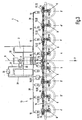
- FIG. 1 is shown an attachment 1 according to the invention and in Fig.2 an enlarged section of the attachment according to Fig.1 with a mechanical main drive train 15, wherein each mowing and conveying element 4,4 ', 4 "or 5,5', 5" is assigned a separate drive element 11 as a manual transmission 12, each with two clutches 13,13 '.
- Fig. 2a for the sake of clarity, an enlarged section Fig.2
- Fig. 2b is powertrain according to Fig. 2 presented in a reversing situation. It shows Fig. 2c he clarity of an enlarged section 2b ,
- FIG. 3 takes also reference back to the Fig.1
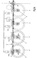
- each mowing and conveying element 4,4 ', 4 "or 5,5', 5" is assigned a separate drive element 11 as a transmission 12, each with a clutches 13,13 '
- Fig. 3a for the sake of clarity, an enlarged section Figure 3
- Fig. 3b is powertrain according to Fig. 3 shown in a reversing situation. It shows Fig. 3c he clarity of an enlarged section 3b ,
- Attachments of this type are known in the art as interchangeable devices and corn heaves and they are received by a connection device of the carrier vehicle 2 and are in driving connection with this.
- the illustrated attachment 1 comprises as an embodiment eight mowing and conveying elements 4, 4 ', 4 ", 5,5', 5", which are supported on a machine frame 3 rotatable about vertical axes 6,6 'and mounted in a bevel gear housing and which differ essentially only by their directions of rotation 14,14 '(14 in the clockwise direction, 14' counterclockwise).
- the mowing and conveying elements 4, 4 ', 4 ", 5,5', 5" driven by vertical axes mow the maize stalks near the ground, trap them in conveying pockets of the mowing and infeed elements and do not transfer them to them illustrated in detail but known in the art transverse conveyor, which then merge them in delivery channels and led out of these fed to the nip 7.
- each of the mowing and conveying elements 4, 4 ', 4 ", 5, 5', 5" individually with regard to their drive, ie to drive them separately or to put them out of operation or to reverse them.
- the control is carried out from the control station 33 or driver's seat from the cab 33 out.
- this is the example of the reversing of the two right in the direction of travel outer mowing and conveying elements 4 ', 5 "in the 2b respectively.
- 3b represented, which is represented symbolically by the thicker lines of these two mowing and conveying elements.
- each of the mowing and conveying elements 4, 4 ', 4 “, 5, 5', 5" can be controlled selectively in the aforementioned sense. It is provided that the mowing and conveying elements 4, 4 ', 4 "5, 5 'drive elements 11 are assigned, by the actuation of which the directions of rotation 14, 14' can be changed from the driver's seat of the carrier vehicle 2.
- Each mowing and conveying element 4, 4", 4 ", 5, 5 ', 5 " is associated with at least one speed sensor (16) and a direction of rotation sensor (17)
- An embodiment of the invention provides that in the mechanical drive train 15, which is arranged in the rear region 10 of the attachment 1, drive elements are arranged as a manual transmission (12) in series and from this the required drive torque for the mowing and conveying elements. 4 ; 4 ', 4 ", 5,5', 5". As switching elements acting as the drive element 11 clutches 13,13 'are exemplified.
- the transmission 12 are traversed by the transverse to the travel and working direction F main drive train 1, - which is drivingly connected to the drive motor of the carrier vehicle 2, and the mowing and conveying elements 4, 4 ', 4 ", 5.5', 5 “are thus coupled on the drive side with this.
- each shift gear contain only a clutch 13, this embodiment makes it necessary that reversing the direction of rotation of the main drive train vice versa, ie also reversed, as this is already the case in known embodiments of the main drive train 15.
- each individual drive connection to the respective mowing and conveyor discs can then be made or interrupted, which thus makes it possible to selectively connect or disconnect the individual mowing and conveying elements, and this both in normal operation and in reversing.
- the clutch 13,13 ' is an integral part of the gearbox (12) and it is advantageously designed as a switchable multi-plate clutch.
- the gears themselves are in the embodiments as bevel gear shown, which is to be regarded as exemplary only. Likewise, these may be other embodiments of manual transmissions, as these are widely known in drive technology.
- FIG. 4 also showed a header 1 according to the invention, however, with a hydraulic drive of the mowing and conveying elements and in Figure 5 an enlarged section of the attachment according to Figure 4 shown.
- Fig. 6 shows the complete hydraulic drive system in a simplified representation according to the rules of hydraulic circuit diagrams.
- the main drive train according to the invention may also consist of a hydraulic shaft as a hydraulic drive system 23, so that the drive element 11 is a hydraulic motor 18, which is in drive connection with the drive motor of the carrier vehicle 2 via a hydraulic pump 19,19 '.
- a load-sensing controlled double pump 37 which consists of two individual hydraulic pumps 19 ', 19 "with pressure cut 25 as overload protection 21, and by the PTO of the carrier vehicle 2 via the drive pin 34 of a central gear 34, as executed
- both hydraulic pumps 19, 19 ' can be actuated separately, preferably swash plate type variable displacement pumps for closed loop mobile applications, but in principle they can also be used in an open circuit the hydraulic pumps 19,19 'designed as variable displacement pumps with zero position, so that they deliver no displacement in the zero stroke and in both directions can be swung through, so that the flow reverses its flow direction.
- each mowing and conveying element 4,4 ', 4', 5,5 ', 5 "still a separate switching element is assigned as an actuator (20) as 4-3- directional control valve with blocking position
- the left and the right half of the attachment not only in groups can be controlled via the pump control with zero stroke, ie either mowing, or out of service or set in reversing, but it is also possible individual mowing and conveying element 4.4 ', 4', 5,5 ', 5 "selectively with the aforementioned operating condition to control. In this case, adjacent mowing and conveying elements can be put out of operation when reversing.
- the directional control valves and the overload protection are designed as pressure limiting valves (24) designed so that they are integrated into the data bus and thus applied to the inputs and outputs of the job computer.
- a hydraulic tank (28) for example, a hollow profile of the machine frame 3 serve.
- each drive element (11) of the mowing and conveying disks is assigned at least one rotational speed sensor 16 and one rotational direction sensor 14, 14 'so that its generated measured values can be visualized on an actuating and monitoring device 32.
- each drive element (11) of a mowing and conveying disc is assigned a slip measuring device (22) which, when a threshold value that is related to a predetermined rated speed is exceeded, can trigger or trigger a stop function.
- the instantaneous driving speed of the carrier vehicle (2) is fed back with the load-sensing control in the sense of power consumption control and / or limitation, whereby the driving speed automatically adapts to the load behavior.
- the job computer is located on the attachment 1 and it is connected by means of a data bus 31, in particular via an ISO bus, with the central controller 30 of the host vehicle and thus can communicate with this.
- the driver of the carrier vehicle (2) has the possibility of the drive elements (11) via the central control device (30) either individually or in groups to control from its driver's seat.
Abstract
Description
Die Erfindung betrifft ein Vorsatzgerät für landwirtschaftliche Erntemaschinen, insbesondere für Feldhäcksler zum Mähen, Aufnehmen und Weiterführen eines stängelartigen Erntegutstroms, beispielsweise für Maispflanzen in den Einzugsspalt des Einzugsgehäuses gemäß dem Oberbegriff des unabhängigen Anspruchs 1.The invention relates to an attachment for agricultural harvesting machines, in particular for forage harvesters for mowing, picking up and continuing a stalk-like Erntegutstroms, for example, for corn plants in the intake nip of the feed housing according to the preamble of the independent claim. 1
Bekannt sind diese Vorsatzgeräte insbesondere auch unter dem Begriff Maisgebisse. Diese sind dem Fachmann in verschiedenen Ausführungen bekannt. Die Aufgabe dieser Vorsatzgeräte für Feldhäcksler besteht darin, die stehenden Maispflanzen während der Vorwärtsfahrt abzumähen und die abgemähten Pflanzen dabei so weiter zu transportieren, dass sie in den Einzugsbereich bzw. in den Einzugsspalt des Einzugsgehäuses des Feldhäckslers gelangen. Bekannt sind Vorsatzgeräte mit mehreren quer zur Fahrt- und Arbeitsrichtung nebeneinander liegenden umlaufend angetriebenen Mäh- und Fördertrommeln mit übereinander liegenden mit Fördertaschen ausgestatteten scheibenförmigen Einzugselementen, denen im rückwärtigen Bereich zusätzlich Querförder- und Umlenkelemente zugeordnet sind.These attachments are also known in particular under the term maize bits. These are known to the expert in various designs. The task of these attachments for forage harvesters is to mow off the standing corn plants during forward travel and to transport the mowed plants so that they reach the catchment area or into the intake gap of the feeder housing of the forage harvester. Attachments are known with several transverse to the direction of travel and working adjacent rotating driven mowing and conveyor drums with superimposed equipped with conveyor pockets disc-shaped retraction elements, which are additionally assigned in the rear region Querförder- and deflection.
Angetrieben werden die Mäh- und Fördertrommeln bzw. Mäh und Förderelemente vom Verbrennungsmotor des Trägerfahrzeugs ausgehend über einen mechanisch angetriebenen Antriebsstrang, wobei den Mäh- und Förderelementen ein sich quer zur Fahrtrichtung erstreckender Antriebsstrang vorgelagert ist, an dem die erforderlichen Antriebsmomente für die Mäh- und Förderelementen mittels Winkelgetrieben abgegriffen werden. Ein derartiger Antrieb ist beispielsweise aus der
Die Aufgabe der Erfindung ist es, ein Vorsatzgerät der zuvor genannten Art vorzuschlagen, welches der Verstopfungsgefahr entgegenwirkt, und falls sich dennoch ein Verstopfungsvorgang anbahnt, diesen schnellstmöglich zu erkennen, um damit dem Ausmaß der Störung schnellstmöglich entgegen zu wirken um damit die vorgenannte Haufwerksbildung weitestgehend zu vermeiden oder zumindest die durch Reversiervorgänge hervorgerufenen Ernteverluste zu minimieren.The object of the invention is to propose an attachment of the aforementioned type, which counteracts the risk of clogging, and if a clogging process nevertheless proposes to recognize this as quickly as possible in order to counteract the extent of the disturbance as quickly as possible so that the aforementioned heap formation as much as possible avoid or at least minimize the losses caused by Reversiervorgänge crop losses.
Gelöst wird die Aufgabe der Erfindung mit den kennzeichnenden Merkmalen des unabhängigen Anspruchs 1. Weitere vorteilhafte Ausgestaltungen der Erfindung sind den abhängigen Ansprüchen, der Beschreibung und den Figurendarstellungen zu entnehmen.The object of the invention is achieved with the characterizing features of independent claim 1. Further advantageous embodiments of the invention are described in the dependent claims, the description and the figure representations.
Die Erfindung sieht dabei vor, dass der Antrieb jedes einzelnen Mäh- und Förderelements unabhängig von den übrigen. Mäh- und Förderelementen vom Führerstand aus der Kabine zu- oder abschaltbar oder reversierbar ist. Dabei können den Mäh- und Förderelementen entweder separate Schaltkupplungen zugeordnet sein, die den Antrieb für das jeweilige Mäh- und Förderelemente mit dem Hauptantriebsstrang herstellen oder unterbrechen oder die Drehrichtungsumkehr herbeiführen, oder aber es kann auch jedem Förderelement ein eigener Antriebsmotor zugeordnet sein, der so angesteuert werden kann, das ebenfalls das jeweilige Mäh- und Förderelemente angetrieben, außer Betrieb gesetzt oder reversiert werden kann.The invention provides that the drive of each mower and conveying element independent of the others. Mowing and conveying elements from the cab from the cabin or can be switched off or reversed. In this case, the mowing and conveying elements can be assigned either separate clutches that produce or interrupt the drive for the respective mowing and conveying elements with the main drive train or cause the direction of rotation reversal, or it can also be assigned to each conveyor element its own drive motor, which is so controlled can be, which also drives the respective mowing and conveying elements, can be put out of action or reversed.
Dabei können die Schaltvorgänge auch von einer zentralen Steuereinheit des Trägerfahrzeugs aus nach einem oder mehreren vorwählbaren und hinterlegten Algorithmen erfolgen oder auch manuell vom Fahrer des Trägerfahrzeugs individuell und selektiv ausgelöst werden.The switching operations can also take place from a central control unit of the carrier vehicle according to one or more preselected and stored algorithms or manually triggered by the driver of the carrier vehicle individually and selectively.
Dabei können beispielsweise gerade beim Reversieren auch gezielt nur die Mäh- und Förderscheiben angesteuert werden, die von der Verstopfung tatsächlich betroffen sind, so dass auch nur das Erntegut rückwärts gefördert wird, welches die Verstopfung verursacht hat. In dem Programmspeicher eines Mikroprozessors können dabei auch verschiedene Algorithmen vor Reversiervorgängen hinterlegt werden, beispielsweise die, dass einzelne Mäh- und Förderscheiben für sich allein genommen unabhängig voneinander ansteuerbar sind oder auch durch Gruppenbildung zwei benachbarte Mäh- und Förderscheiben ansteuerbar sind.In this case, for example, just when reversing targeted only the mowing and conveying discs are controlled by the blockage actually are concerned, so that only the crop is promoted backwards, which has caused the constipation. In the program memory of a microprocessor different algorithms can be deposited before Reversiervorgängen, for example, that individual mowing and conveyor discs taken independently are controlled independently or by grouping two adjacent mowing and conveyor discs are controlled.
Diese Algorithmen können dann auch beispielsweise für die Hochlaufphase der Mäh- und Förderscheiben genutzt werden. Wahlweise kann dabei auch der Antrieb der Vorpresswalzen beim Reversieren mit einbezogen werden, oder wenn sich dieses als unnötig erweist, auch unterbleiben, in dem der Antrieb der Einzugs- und Presswalzen dann während des Reversierens abgeschaltet bleibt.These algorithms can then also be used, for example, for the startup phase of the mowing and conveying discs. Optionally, the drive of the pre-compression rollers can be included in the reversing, or if this proves unnecessary, also omit, in which the drive of the intake and pressing rollers then remains switched off during reversing.
Vorteilhafterweise sind die Schaltkupplungen integraler Bestandteil des jeweiligen Abzweiggetriebes eines Mäh- und Förderelements und sie sind beispielsweise als mit Hilfsenergie betätigbare Schaltkupplungen, beispielsweise als Lamellenkupplung, ausgebildet. Aber auch andere Kupplungsausführungen, wie beispielsweise formschlüssig eingreifende und ausrückbare Klauenkupplungen sind durchaus für diesen Anwendungsfall vorgesehen.Advantageously, the clutches are an integral part of the respective branch gear of a mowing and conveying element and they are, for example, as an auxiliary power actuated clutches, for example as a multi-plate clutch formed. But other coupling designs, such as positively engaging and disengageable jaw clutches are quite intended for this application.
Die Hilfsenergien können dabei elektrischer, hydraulischer oder auch pneumatischer Natur sein. Dabei können die Schaltkupplungen auch gleichzeitig als Überlastkupplungen ausgelegt sein, die bei Überlast beispielsweise den Fahrantrieb des Trägerfahrzeugs anhalten.The auxiliary energy can be electrical, hydraulic or pneumatic nature. The clutches can also be designed as overload clutches at the same time, for example, stop the drive of the host vehicle in case of overload.
Sollte hingegen die Drehzahl eines Antriebselements der zugehörigen Mäh- und Förderscheiben bei Überlast auf einen vorgegebenen Schwellwert absinken, welcher messtechnisch erfasst wird, so wird dadurch ein Signal zum abschalten des betreffenden Antriebs der Mäh- und Förderscheiben erzeugt.If, on the other hand, the rotational speed of a drive element of the associated mowing and conveying disks falls below a predetermined threshold value during overload, which is detected by measurement, a signal for switching off the respective drive of the mowing and conveying disks is thereby generated.
Die Erfindung sieht weiterhin vor, dass das Vorsatzgerät ein eigenes in sich geschlossenes Hydrauliksystem zum Antrieb der Mäh- und Förderscheiben aufweist, welches z.B. mit einer Zapfwelle des Trägerfahrzeugs antriebsseitig in Wirkverbindung steht. Besonders vorteilhaft ist dabei die Auslegung des Hydrauliksystems als lastabhängig geregeltes load-sensing - System im geschlossenen Kreislauf mit Druckabschneidung, welches in sich eine kostengünstige und funktionssichere Überlastsicherung beinhaltet. Auch ist dabei möglich, dass von einer Hydraulikpumpe mehrere in sich geschlossene Arbeitskreisläufe ausgehen, welches den Kostenaufwand reduziert. Das Hydraulische Antriebssystem kann dabei vorteilhafterweise ein druckgeregeltes und/oder Förderstrom geregeltes load-sensing System sein, welches besonders zum Energiesparen eingesetzt werden kann.The invention further provides that the attachment has its own self-contained hydraulic system for driving the mowing and conveying discs, which e.g. is in operative connection with a PTO shaft of the carrier vehicle on the drive side. Particularly advantageous is the design of the hydraulic system as a load-dependent controlled load-sensing system in a closed circuit with pressure cut, which includes a cost-effective and functionally reliable overload protection. It is also possible that emanate from a hydraulic pump several self-contained working cycles, which reduces the cost. The hydraulic drive system can advantageously be a pressure-controlled and / or flow regulated load-sensing system, which can be used especially for energy saving.
Die messtechnische Erfassung und Auswertung erfolgt aus dem Zusammenwirken von Drehzahl und Drehrichtungssensoren, die vorteilhafterweise mit den entsprechenden Antriebselementen direkt in Wirkverbindung stehen oder Teil dieser sind.The metrological detection and evaluation takes place from the interaction of speed and direction of rotation sensors, which are advantageously in operative connection with the corresponding drive elements or part of this.
Die so detektierten Eingangsgrößen stellen somit wichtige Eingangsgrößen eines Jobrechners dar, der erfindungsgemäß Teil des Vorsatzgerätes ist und der vorteilhafter Weise in ein Bus-System, beispielsweise in einen ISO-Bus eingebunden ist Die weitere Ausgestaltung der Erfindung sieht vor, diesen Jobrechner über eine BUS-Verbindung auch mit der zentralen Steuerung des Trägerfahrzeugs zu verbinden und auch an dessen Betätigungs- und Überwachungseinrichtung anzukoppeln, so dass der Prozessablauf auch visualisiert werden kann.The thus detected input variables thus represent important input variables of a job computer, which according to the invention is part of the attachment and which Advantageously, integrated into a bus system, for example in an ISO bus The further embodiment of the invention provides to connect this job computer via a bus connection with the central control of the host vehicle and also to couple to the actuation and monitoring device, so that the process flow can also be visualized.
Die Erfindung ist exemplarisch an dem nachfolgenden Ausführungsbeispiel dargestellt und beschrieben.The invention is illustrated and described by way of example in the following exemplary embodiment.
Nähere Einzelheiten der Erfindung sind den nachfolgenden Figurendarstellungen und deren Beschreibungen zu entnehmen.Further details of the invention are given in the following figure representations and their descriptions.
Es zeigen:
- Fig. 1
- zeigt ein Vorsatzgerät nach der Erfindung in vereinfachten Darstellung in einer Draufsicht in Betriebsstellung
- Fig. 2
- zeigt das Vorsatzgerät gemäß
Fig.1 mit einem mechanischen Antriebsstrang nach der Erfindung - Fig. 2a
- zeigt einen vergrößerten Ausschnitt aus
Fig.2 - Fig. 2b
- zeigt den Antriebsstrang gemäß
Fig. 2 in einer Reversiersituation - Fig. 2c
- zeigt einen vergrößerten Ausschnitt aus
Fig.2b - Fig. 3
- zeigt das Vorsatzgerät gemäß
Fig.1 mit einem weiteren mechanischen Antriebsstrang nach der Erfindung - Fig. 3a
- zeigt einen vergrößerten Ausschnitt aus
Fig.3 - Fig. 3b
- zeigt den Antriebsstrang gemäß
Fig. 3 in einer Reversiersituation - Fig. 3c
- zeigt einen vergrößerten Ausschnitt aus
Fig.3b - Fig. 4
- zeigt das Vorsatzgerät gemäß
Fig.1 mit einem hydraulischen Antriebsstrang nach der Erfindung - Fig. 5
- zeigt einen vergrößerten Ausschnitt aus
Fig.4 - Fig. 4
- zeigt einen vereinfachten Hydraulikschaltplan für den hydraulischen Antriebsstrang nach der Erfindung
- Fig. 6
- zeigt das komplette hydraulische Antriebssystem in einer vereinfachten Darstellung,
- Fig. 1
- shows a header according to the invention in a simplified representation in a plan view in the operating position
- Fig. 2
- shows the attachment according to
Fig.1 with a mechanical drive train according to the invention - Fig. 2a
- shows an enlarged section
Fig.2 - Fig. 2b
- shows the drive train according to
Fig. 2 in a reversing situation - Fig. 2c
- shows an enlarged section
2b - Fig. 3
- shows the attachment according to
Fig.1 with another mechanical drive train according to the invention - Fig. 3a
- shows an enlarged section
Figure 3 - Fig. 3b
- shows the drive train according to
Fig. 3 in a reversing situation - Fig. 3c
- shows an enlarged section
3b - Fig. 4
- shows the attachment according to
Fig.1 with a hydraulic drive train according to the invention - Fig. 5
- shows an enlarged section
Figure 4 - Fig. 4
- shows a simplified hydraulic circuit diagram for the hydraulic drive train according to the invention
- Fig. 6
- shows the complete hydraulic drive system in a simplified representation,
In
Es handelt sich dabei um ein Maisgebisse in vereinfachter Darstellung in einer Draufsicht. Die Drehrichtungspfeile 14,14' zeigen die Drehrichtungen der Förderscheiben der Mäh- und Förderelemente 4,4',4" bzw. 5,5',5" im Mähbetrieb. Das Vorsatzgerät ist in bekannter Weise an ein Trägerfahrzeug 2, welches als selbstfahrender Feldhäcksler ausgebildet ist, vor dessen Einzugsgehäuse 8 mit seinem Einzugsspalt 7 angebaut.It is a corn in a simplified representation in a plan view. The direction of
Vorsatzgeräte dieser Art sind dem Fachmann als auswechselbare Einrichtungen und Maisgebisse bekannt und sie werden von einer Anschlusseinrichtung des Trägerfahrzeugs 2 aufgenommen und stehen mit diesem in Antriebsverbindung.Attachments of this type are known in the art as interchangeable devices and corn heaves and they are received by a connection device of the
Das dargestellte Vorsatzgerät 1 umfasst als Ausführungsbeispiel acht Mäh- und Förderelemente 4;4',4",5,5',5", die sich an einem Maschinengestell 3 drehbar um Hochachsen 6,6' und gelagert in einem Winkelgetriebegehäuse abstützen und die sich im wesentlichen lediglich durch ihre Drehrichtungen 14,14' (14 im Urzeigersinn , 14' entgegen dem Urzeigersinn) unterscheiden. Die von den um Hochachsen angetriebenen Mäh- und Förderelemente 4;4',4",5,5',5" mähen die Maisstängel in der Nähe des Bodens ab, fangen sie in Fördertaschen der Mäh- und Einzugselemente ein und übergeben sie an nicht näher dargestellte aber dem Fachmann bekannte Querförderer, die sie dann in Förderkanälen zusammenführen und von diesen geführt dem Einzugsspalt 7 zuführen. Die Mäh- und Förderelemente 4;4',4",5,5',5" und ihre Drehrichtungen 14,14' sind lediglich beispielhaft dargestellt und es können je nach Ausführung und Arbeitsbreite A mehr oder weniger Mäh- und Förderelemente sein.The illustrated attachment 1 comprises as an embodiment eight mowing and conveying
Erfindungsgemäß ist es nun möglich, jedes der Mäh- und Förderelemente 4;4',4",5,5',5" hinsichtlich seines Antriebs einzeln anzusteuern, d.h. diese separat umlaufend anzutreiben oder diese außer Betrieb zu setzen oder zu reversieren. Die Ansteuerung erfolgt vom Steuerstand 33 bzw. Fahrersitz aus der Fahrerkabine 33 heraus. Exemplarisch ist diese am Beispiel der Reversierung der beiden in Fahrtrichtung rechten äußeren Mäh- und Förderelemente 4',5" in den
Alle übrigen Mäh- und Förderelemente 4',5" stehen dabei still, welches bedeutet, dass sie außer Betrieb gesetzt sind, wie auch die fehlenden Drehrichtungspfeile an diesen außer Betrieb gesetzten Mäh- und Förderelementen dieses symbolisch darstellen.
Hingegen haben sich die Drehrichtungen der beiden äußeren im Reversierzustand befindlichen Mäh- und Förderelemente im Vergleich zur
All other mowing and conveying
By contrast, the directions of rotation of the two outer mowing and conveying elements in reversing state have compared to
Ermöglicht wird dieses dadurch, dass die Drehrichtung 14 oder 14' wenigstens eines Mäh- und Förderelements 4;4',4",5,5',5" unabhängig von den übrigen Mäh- und Förderelementen 4;4',4",5,5',5" des Vorsatzgerätes 1 veränderbar ist und somit auch, dass wenigstens ein Mäh- und Förderelement 4;4',4",5,5',5" unabhängig von den übrigen. Mäh- und Förderelementen 4;4',4",5,5',5" des Vorsatzgerätes (1) reversierbar und/oder außer Betrieb setzbar ist. Erfindungsgemäß ist aber auch vorgesehen, dass jedes der Mäh- und Förderelemente 4;4',4",5,5',5" selektiv im vorgenannten Sinne ansteuerbar ist Dabei ist vorgesehen, dass den Mäh- und Förderelementen 4;4',4",5,5',5' Antriebselemente 11 zugeordnet sind, durch deren Ansteuerung die Drehrichtungen 14,14' vom Fahrersitz des Trägerfahrzeugs 2 aus veränderbar sind. Jedem Mäh- und Förderelement 4;4',4",5,5',5" ist wenigstens ein Drehzahlsensor (16) und ein Drehrichtungssensor (17) zugeordnetThis is made possible by the fact that the direction of
Eine Ausführungsform der Erfindung sieht dabei vor, dass in dem mechanischen Antriebsstrang 15, der im rückwärtigen Bereich 10 des Vorsatzgerätes 1 angeordnet ist, Antriebselemente als Schaltgetriebe (12) in Reihe angeordnet sind und die von diesem das erforderliche Antriebsdrehmoment für die Mäh- und Förderelemente 4;4',4",5,5',5" abgreifen. Als Schaltelemente sind beispielhaft die als Antriebselement 11 fungierenden Schaltkupplungen 13,13' dargestellt.An embodiment of the invention provides that in the
Somit werden die Schaltgetriebe 12 von dem quer zur Fahrt- und Arbeitsrichtung F verlaufender Hauptantriebsstrang 1, - welcher mit dem Antriebsmotor des Trägerfahrzeugs 2 in Antriebsverbindung steht, durchsetzt und die Mäh- und Förderelemente 4;4',4",5,5',5" sind damit antriebsseitig mit diesem gekoppelt.Thus, the transmission 12 are traversed by the transverse to the travel and working direction F main drive train 1, - which is drivingly connected to the drive motor of the
Dadurch, dass die Schaltkupplungen 13,13' eines Schaltgetriebes 12 derart in Wechselwirkung zueinander stehen, dass sie durch die Art ihrer Beschaltung die Antriebsverbindung zu den Mäh- und Förderelementen 4;4',4",5,5',5" entweder schließen oder öffnen. Im Ausführungsbeispiel gemäß
Im Ausführungsbeispiel
Somit ist für jedes einzelne Mäh- und Förderelement 4;4',4",5,5',5" der Betriebszustand Normalbetrieb, Stillstand oder Reversierbetrieb ansteuerbar. Die Schaltkupplung 13,13' ist dabei integraler Bestandteil des Schaltgetriebes (12) und sie ist vorteilhafterweise als schaltbare Lamellenkupplung ausgebildet. Die Getriebe selber sind in den Ausführungsbeispielen als Kegelradgetriebe dargestellt, welches nur als beispielhaft anzusehen ist. Genauso kann es sich dabei um andere Ausführungsformen von Schaltgetrieben handeln, wie diese in der Antriebstechnik vielfältig bekannt sind.Thus, for each individual mowing and conveying
In
Wie in
Dabei ist jedem Antriebselement 11 als Hydraulikmotor 18 eine Überlastsicherung (21) zugeordnet, welche bei Überschreitung eines vorgegebenen Schwellwertes, der in Beziehung zu einem maximal vorgegebenen Antriebsdrehmoment steht, anspricht, und auch eine Stop-Funktion auslösen kann. Vorteilhafterweise sind die Wegeventile und die Überlastsicherung ausgebildet als Druckbegrenzungsventile (24) so ausgestaltet, dass sie in den Datenbus eingebunden sind und damit an den Ein- und Ausgängen des Jobrechners anliegen. Als Hydrauliktank (28) kann beispielsweise auch ein Hohlprofil des Maschinengestells 3 dienen.In this case, each drive element 11 as a
Erfindungsgemäß ist jedem Antriebselement (11) der Mäh- und Förderscheiben wenigstens ein Drehzahlsensor 16 und ein Drehrichtungssensor 14,14' zugeordnet, so dass dessen generierte Messwerte auf einer Betätigungs- und Überwachungseinrichtung 32 visualisiert werden können.According to the invention, each drive element (11) of the mowing and conveying disks is assigned at least one
Erfindungsgemäß ist jedem Antriebselement (11) einer Mäh- und Förderscheibe eine Schlupfmesseinrichtung (22) zugeordnet, welche bei Überschreitung eines Schwellwertes, der in Beziehung zu einer vorgegebenen Nenndrehzahl steht, eine Stop-Funktion auslöst oder auslösen kann.According to the invention, each drive element (11) of a mowing and conveying disc is assigned a slip measuring device (22) which, when a threshold value that is related to a predetermined rated speed is exceeded, can trigger or trigger a stop function.
Möglich ist auch, dass dabei die momentane Fahrgeschwindigkeit des Trägerfahrzeugs (2) mit der load-sensing Regelung im Sinne einer Leistungsaufnahmeregelung und/oder -begrenzung rückgekoppelt ist, wodurch die Fahrgeschwindigkeit sich dem Lastverhalten automatisch anpasst.It is also possible that in this case the instantaneous driving speed of the carrier vehicle (2) is fed back with the load-sensing control in the sense of power consumption control and / or limitation, whereby the driving speed automatically adapts to the load behavior.
Der Jobrechner befindet sich dabei auf dem Vorsatzgerät 1 und er ist mittels eines Datenbusses 31, insbesondere über einen ISO-Bus, mit der zentralen Steuerung 30 des Trägerfahrzeugs verbunden und kann somit mit dieser kommunizieren.The job computer is located on the attachment 1 and it is connected by means of a
Dadurch hat der Fahrer des Trägerfahrzeugs (2) die Möglichkeit, die Antriebselemente (11) über die zentrale Steuereinrichtung (30) wahlweise einzeln oder gruppenweise von seinem Fahrersitz aus anzusteuern.As a result, the driver of the carrier vehicle (2) has the possibility of the drive elements (11) via the central control device (30) either individually or in groups to control from its driver's seat.
- 11
- Vorsatzgerätheader
- 22
- Trägerfahrzeug (Erntemaschine, Feldhäcksler)Carrier vehicle (harvester, forage harvester)
- 33
- Maschinengestellmachine frame
- 4,4',4"4,4 ', 4 "
- Mäh- und Förderelement (Mäh- und Fördertrommel)Mowing and conveying element (mowing and conveying drum)
- 5,5',5"5,5 ', 5 "
- Mäh- und Förderelement (Mäh- und Fördertrommel)Mowing and conveying element (mowing and conveying drum)
- 6,6'6.6 '
- Hochachsenvertical axes
- 77
- Einzugsspaltnip
- 88th
- Einzugsgehäusefeeder housing
- 99
- vertikale Längsmittelebenevertical longitudinal center plane
- 1010
- rückwärtiger Bereichbackward area
- 1111
- Antriebselementdriving element
- 1212
- Schaltgetriebemanual transmission
- 13,13'13.13 '
- Schaltkupplungclutch
- 1414
- Drehrichtung im Urzeigersinn (rechtsdrehend)Direction of rotation in the clockwise direction (clockwise)
- 14'14 '
- Drehrichtung gegen Urzeigersinn (linksdrehend)Counterclockwise rotation (counterclockwise)
- 1515
- HauptantriebsstrangMain drive train
- 1616
- DrehzahlsensorSpeed sensor
- 1717
- DrehrichtungssensorDirection of rotation sensor
- 1818
- Hydraulikmotorhydraulic motor
- 19,19'19.19 '
- Hydraulikpumpehydraulic pump
- 2020
- Betätigungseinrichtungactuator
- 2121
- ÜberlastsicherungOverload protection
- 2222
- SchlupfmesseinrichtungSlip measuring device
- 2323
- hydraulisches Antriebssystemhydraulic drive system
- 2424
- DruckbegrenzungseinrichtungPressure limiting device
- 2525
- Druckabschneidungpressure cut
- 2626
- Steuerventil, WegeventilControl valve, directional control valve
- 2727
- Steuereinrichtungcontrol device
- 2828
- Hydrauliktankhydraulic tank
- 2929
- Mikroprozessormicroprocessor
- 3030
- zentrale Steuereinrichtung des Trägerfahrzeugscentral control device of the carrier vehicle
- 3131
- Datenbusbus
- 3232
- Betätigungs- und ÜberwachungseinrichtungActuation and monitoring device
- 3333
- Führerstandcab
- 3434
- Mittelgetriebemeans gear
- 3535
- Antriebszapfendrive journal
- 3636
- KegelstirnradgetriebeBevel
- 3737
- Doppelpumpedouble pump
- 3838
- Mengenteilerflow divider
- 3939
- ZahnradvorgelegeGear train
- AA
- Arbeitsbreiteworking width
- FF
- Fahrt- und ArbeitsrichtungDriving and working direction
Claims (31)
- A front-mounted implement (1) for agricultural harvesters for cutting, picking up and further conveying a stalk-like crop material flow into the intake gap (7) of the intake housing (8) of the harvester (2) for further processing, comprising at least two respective cutting and conveyor elements (4, 5), (4', 5') which are spaced on both sides of the vertical longitudinal central plane (9, 9') and which are driven in rotation about upright axes (6, 6'), characterised in that the drive of each individual cutting and conveyor element can be cut in or out or reversed independently of the other cutting and conveyor elements from the driving position of the cab.
- A front-mounted implement (1) according to claim 1 characterised in that the shift operations are effected by a central control unit of the carrier vehicle in accordance with one or more preselectable and stored algorithms or can be individually and selectively triggered manually by the driver of the carrier vehicle.
- A front-mounted implement (1) according to claim 1 and claim 2 characterised in that associated with the cutting and conveyor elements (4; 4', 4", 5, 5', 5") are drive elements (11, 12), by the actuation of which the directions of rotation (14, 14') can be changed.
- A front-mounted implement (1) according to claim 3 characterised in that a drive element (11) is a shift transmission (12).
- A front-mounted implement (1) according to claim 3 characterised in that the drive element (11) is a shift clutch (13, 13').
- A front-mounted implement (1) according to claim 3 characterised in that the drive element (11, 12, 13, 13') can be coupled to a main drive train (15) drivingly connected to the drive engine of the carrier vehicle (2).
- A front-mounted implement (1) according to claim 3 characterised in that the drive element (11) is a hydraulic motor (18) drivingly connected to the drive engine of the carrier vehicle (2).
- A front-mounted implement (1) according to claim 3 characterised in that associated with each drive element (11) is a shift element as an actuating device (20) for cutting in, cutting out and/or reversing the direction of rotation.
- A front-mounted implement (1) according to claim 3 characterised in that associated with each drive element (11) is an overload safeguard means (21) which responds when a predetermined threshold value related to a maximum predetermined drive torque is exceeded, and triggers a stop function.
- A front-mounted implement (1) according to claim 3 characterised in that at least one rotary speed sensor (16) is associated with each drive element (11).
- A front-mounted implement (1) according to claim 3 characterised in that at least one rotary direction sensor (17) is associated with each drive element (11).
- A front-mounted implement (1) according to claim 3 characterised in that associated with each drive element (11) is a slip measuring device (22) which triggers a stop function when a threshold value related to a predetermined nominal rotary speed is exceeded.
- A front-mounted implement (1) according to claim 4 characterised in that the shift transmission (12) has at least one shift clutch (13 or 13').
- A front-mounted implement (1) according to claim 4 characterised in that the shift transmission (12) has two shift clutches (13, 13').
- A front-mounted implement (1) according to claim 5 characterised in that the shift clutches (13, 13') of a shift transmission (12) are in mutually interacting relationship in such a way that they either close, open or reverse the drive connection to the cutting and conveyor elements (4; 4', 4", 5, 5', 5") by virtue of the nature of their connection to the main drive train (15).
- A front-mounted implement (1) according to claim 5 characterised in that the shift clutch or clutches (13, 13') is or are an integral component of the shift transmission (12).
- A front-mounted implement (1) according to claim 5 characterised in that a shift clutch (13, 13') is in the form of a multi-plate clutch.
- A front-mounted implement (1) according to claim 1 or claim 2 characterised in that the front-mounted implement (2) has a hydraulic drive system (23) which is closed in itself for driving the cutting and conveyor elements (4; 4', 4", 5, 5', 5 ").
- A front-mounted implement (1) according to claim 18 characterised in that the closed hydraulic drive system (23) substantially comprises a pump station (19), hydraulic motors (18) with the associated control valves (26), a pressure limiting device (26) and a hydraulic tank (28), the drive of the hydraulic pump (19) being drivingly connected to the drive engine of the carrier vehicle (2).
- A front-mounted implement (1) according to claim 18 characterised in that the hydraulic drive system (23) is a load-sensing system regulated in load-dependent relationship.
- A front-mounted implement (1) according to claim 18 characterised in that the hydraulic drive system (23) is a pressure-regulated and/or conveyor flow-regulated load-sensing system.
- A front-mounted implement (1) according to claim 18 characterised in that the hydraulic drive system (23) has a closed hydraulic circuit.
- A front-mounted implement (1) according to claim 18 characterised in that a pressure cut-off means (25) is associated as an overload safeguard means (21) with each hydraulic motor (18).
- A front-mounted implement (1) according to claims 1 to 23 characterised in that the front-mounted implement is controllable by a central control device of the carrier vehicle.
- A front-mounted implement (1) according to one of claims 1 to 24 characterised in that the front-mounted implement (1) accommodates a job computer (29).
- A front-mounted implement (1) according to claims 24 and 25 characterised in that the job computer (29) and the actuating and monitoring device (32) of the carrier vehicle (2) communicate by way of a data bus connection, in particular by way of an ISO bus.
- A front-mounted implement (1) according to claims 24 to 26 characterised in that the control device (27) and the central control device (30) of the carrier vehicle (2) communicate by way of a data bus connection (31).
- A front-mounted implement (1) according to claims 24 to 27 characterised in that the driver of the carrier vehicle (2) can actuate the drive elements (11) selectively individually or group-wise by way of the central control device (30).
- A front-mounted implement (1) according to claims 1 to 30 characterised in that selective actuation permits all or individual drive elements (10) or groups thereof to be brought into or out of operation or reversed.
- A front-mounted implement (1) according to claim 18 characterised in that the instantaneous speed of travel of the carrier vehicle (2) is fed back to the load-sensing regulation to provide a power consumption limitation.
- A front-mounted implement (1) according to claims 1 to 30 characterised in that the front-mounted implement is a corn cutter tooth arrangement.
Applications Claiming Priority (1)
| Application Number | Priority Date | Filing Date | Title |
|---|---|---|---|
| DE102006025455A DE102006025455A1 (en) | 2006-05-30 | 2006-05-30 | Attachment for harvesting stemmed crops |
Publications (2)
| Publication Number | Publication Date |
|---|---|
| EP1862057A1 EP1862057A1 (en) | 2007-12-05 |
| EP1862057B1 true EP1862057B1 (en) | 2009-12-02 |
Family
ID=38197876
Family Applications (1)
| Application Number | Title | Priority Date | Filing Date |
|---|---|---|---|
| EP07008714A Active EP1862057B1 (en) | 2006-05-30 | 2007-04-27 | Attachment device for harvesting stalk crops |
Country Status (4)
| Country | Link |
|---|---|
| US (1) | US7640718B2 (en) |
| EP (1) | EP1862057B1 (en) |
| AT (1) | ATE450136T1 (en) |
| DE (2) | DE102006025455A1 (en) |
Cited By (2)
| Publication number | Priority date | Publication date | Assignee | Title |
|---|---|---|---|---|
| DE102016118353A1 (en) | 2016-09-28 | 2018-03-29 | Claas Selbstfahrende Erntemaschinen Gmbh | Forage harvester with a Erntegutbearbeitungskanal and a measuring bar for detecting a transverse distribution of the crop in the Erntegutbearbeitungskanal |
| EP4115722A1 (en) * | 2021-07-08 | 2023-01-11 | Deere & Company | A disc mower having independently controllable cutter assemblies |
Families Citing this family (17)
| Publication number | Priority date | Publication date | Assignee | Title |
|---|---|---|---|---|
| DE102007002659A1 (en) | 2007-01-18 | 2008-08-07 | Maschinenfabrik Kemper Gmbh & Co. Kg | Machine for mowing stalk-like crops |
| US7669393B2 (en) * | 2008-05-08 | 2010-03-02 | Deere & Company | Stall detection system for mower blade clutch engagement |
| NL1035973C (en) * | 2008-09-24 | 2010-03-25 | Lely Patent Nv | AGRICULTURAL MACHINE. |
| US7730701B1 (en) * | 2009-04-01 | 2010-06-08 | Cnh America Llc | Variable speed hydraulic conditioner drive |
| DE102010031363A1 (en) * | 2010-07-15 | 2012-01-19 | Maschinenfabrik Kemper Gmbh & Co. Kg | Machine for harvesting stalk-like plants with an electric motor driven cutting device |
| US8490371B2 (en) * | 2011-12-20 | 2013-07-23 | Cnh Canada, Ltd. | Modular electric disc cutterbar and controller |
| DE102012106603A1 (en) * | 2012-07-20 | 2014-05-15 | Claas Hungaria Kft. | Series independent attachment for harvesting stemmed crops |
| US9072221B2 (en) | 2013-03-21 | 2015-07-07 | Deere & Company | Sectional driveshaft arrangement for a corn head |
| US9668415B2 (en) | 2013-12-30 | 2017-06-06 | Cnh Industrial America Llc | Basecutter blade control for a cane harvester |
| US9578804B2 (en) * | 2014-04-23 | 2017-02-28 | Cnh Industrial America Llc | Header for an agricultural harvester with independent sub-system drives |
| DE102014109688B4 (en) * | 2014-07-10 | 2024-05-02 | Claas Saulgau Gmbh | Method and control device for operating a harvesting machine |
| DE102014110572A1 (en) * | 2014-07-25 | 2016-01-28 | Claas Saulgau Gmbh | Method and control device for operating a harvester |
| DE102014118781A1 (en) * | 2014-12-16 | 2016-06-16 | Claas Saulgau Gmbh | Method and control device for operating a harvester |
| US10694671B2 (en) * | 2018-04-19 | 2020-06-30 | Cnh Industrial America Llc | Header with multiple row elements |
| DE102021114960A1 (en) | 2020-06-30 | 2021-12-30 | Deere & Company | Harvesting attachment for harvesting stem-like plants with a variable-speed driven mulching device |
| DE102021120326A1 (en) | 2021-08-04 | 2023-02-09 | Deere & Company | Drive system for a harvesting machine |
| DE102022119419A1 (en) | 2022-08-02 | 2024-02-08 | Claas Saulgau Gmbh | Attachment of an agricultural harvester |
Family Cites Families (8)
| Publication number | Priority date | Publication date | Assignee | Title |
|---|---|---|---|---|
| FR2566992B1 (en) * | 1984-07-06 | 1988-10-14 | Kuhn Sa | ROTARY MOWER. |
| GB2289201A (en) * | 1994-05-07 | 1995-11-15 | Ford New Holland Nv | Drive reversal for agricultural harvester |
| US5784866A (en) * | 1996-06-25 | 1998-07-28 | New Holland North America, Inc. | Disc cutterbar for agricultural implements |
| DE59601548D1 (en) * | 1995-09-30 | 1999-05-06 | Kemper Gmbh Maschf | Mowing device |
| DE19544182B4 (en) | 1995-11-27 | 2006-05-04 | Claas Saulgau Gmbh | Agricultural device for harvesting stemmed stalks |
| DE19615882C2 (en) * | 1996-04-22 | 1998-11-19 | Claas Saulgau Gmbh | Cutting and conveying device for stalked stalks |
| DE29702902U1 (en) * | 1997-02-19 | 1998-06-18 | Kemper Gmbh Maschf | Machine for row-independent mowing of maize and the like stem-like crop |
| DE19951644A1 (en) * | 1999-10-27 | 2001-05-17 | Kemper Gmbh Maschf | Agricultural machine, in particular mower |
-
2006
- 2006-05-30 DE DE102006025455A patent/DE102006025455A1/en not_active Withdrawn
-
2007
- 2007-04-27 AT AT07008714T patent/ATE450136T1/en active
- 2007-04-27 EP EP07008714A patent/EP1862057B1/en active Active
- 2007-04-27 DE DE502007002146T patent/DE502007002146D1/en active Active
- 2007-05-30 US US11/755,214 patent/US7640718B2/en active Active
Cited By (3)
| Publication number | Priority date | Publication date | Assignee | Title |
|---|---|---|---|---|
| DE102016118353A1 (en) | 2016-09-28 | 2018-03-29 | Claas Selbstfahrende Erntemaschinen Gmbh | Forage harvester with a Erntegutbearbeitungskanal and a measuring bar for detecting a transverse distribution of the crop in the Erntegutbearbeitungskanal |
| EP3300581A1 (en) | 2016-09-28 | 2018-04-04 | CLAAS Selbstfahrende Erntemaschinen GmbH | Field harvester comprising a crop processing channel and a measuring block for detecting a transverse distribution of crops in the crop processing channel |
| EP4115722A1 (en) * | 2021-07-08 | 2023-01-11 | Deere & Company | A disc mower having independently controllable cutter assemblies |
Also Published As
| Publication number | Publication date |
|---|---|
| DE502007002146D1 (en) | 2010-01-14 |
| DE102006025455A1 (en) | 2007-12-20 |
| US20070289281A1 (en) | 2007-12-20 |
| ATE450136T1 (en) | 2009-12-15 |
| EP1862057A1 (en) | 2007-12-05 |
| US7640718B2 (en) | 2010-01-05 |
Similar Documents
| Publication | Publication Date | Title |
|---|---|---|
| EP1862057B1 (en) | Attachment device for harvesting stalk crops | |
| EP1609351B1 (en) | Harvester head drive | |
| DE69532870T2 (en) | Power drive series for agricultural harvesters | |
| EP1570724B1 (en) | Driving assembly to drive a harvester head of a harvester | |
| BE1023763B1 (en) | DRIVE SYSTEM FOR A MINING MACHINE | |
| EP2952087B1 (en) | Drive system for a self-propelled harvesting machine | |
| DE60101215T2 (en) | FEED CONTROL FOR FIELD CHOPPER | |
| EP2407022B1 (en) | Machine for harvesting stalk-like plants with a cutting device powered by an electric motor | |
| EP2329981B1 (en) | Drive assembly and method for a work machine with two combustion engines | |
| EP3326446B1 (en) | Speed control of a harvesting machine | |
| BE1021620B1 (en) | DRIVE SYSTEM FOR A MINING MACHINE | |
| BE1023764B1 (en) | FELDHÄCKSLER WITH REVERSIBLE CONDITIONING DEVICE | |
| EP1864567B1 (en) | Pick-up | |
| DE102013214986B4 (en) | Drive system for a feed conveyor or header of a harvesting machine with direction-dependent maximum torque | |
| EP2132975B1 (en) | Drive system for an agricultural harvester | |
| DE102009028094B4 (en) | Self-propelled harvester | |
| EP2168420B1 (en) | Agricultural harvester | |
| DE102009028056A1 (en) | Self-propelled agricultural harvester i.e. field chopper, has driving belt drivable by belt pulley, and combustion engines comprising crank shafts in drive connection with belt pulley by belt drive and drive shaft, respectively | |
| BE1022788B1 (en) | MACHINE FOR MOWERING PEGATIVE HARVEST WITH SUCCESSIVE INCREASING CRANE SPEED | |
| EP3348135B1 (en) | Drive system for a harvesting attachment of a harvesting machine with automatic shut-off in the case of overload | |
| EP1566090A1 (en) | Machine for cutting standing crops | |
| DE102017214097A1 (en) | Drive system for a header of a harvester with automatic shutdown in case of overload | |
| DE102010048876A1 (en) | Agricultural working machine | |
| BE1027694B1 (en) | Drive arrangement for an agricultural implement with mechanical overload clutch and automatic adjustment of the switch-off torque | |
| EP1932417B1 (en) | Device for collecting crops lying on the ground |
Legal Events
| Date | Code | Title | Description |
|---|---|---|---|
| PUAI | Public reference made under article 153(3) epc to a published international application that has entered the european phase |
Free format text: ORIGINAL CODE: 0009012 |
|
| AK | Designated contracting states |
Kind code of ref document: A1 Designated state(s): AT BE BG CH CY CZ DE DK EE ES FI FR GB GR HU IE IS IT LI LT LU LV MC MT NL PL PT RO SE SI SK TR |
|
| AX | Request for extension of the european patent |
Extension state: AL BA HR MK YU |
|
| 17P | Request for examination filed |
Effective date: 20080605 |
|
| 17Q | First examination report despatched |
Effective date: 20080708 |
|
| AKX | Designation fees paid |
Designated state(s): AT BE BG CH CY CZ DE DK EE ES FI FR GB GR HU IE IS IT LI LT LU LV MC MT NL PL PT RO SE SI SK TR |
|
| GRAP | Despatch of communication of intention to grant a patent |
Free format text: ORIGINAL CODE: EPIDOSNIGR1 |
|
| GRAS | Grant fee paid |
Free format text: ORIGINAL CODE: EPIDOSNIGR3 |
|
| GRAA | (expected) grant |
Free format text: ORIGINAL CODE: 0009210 |
|
| AK | Designated contracting states |
Kind code of ref document: B1 Designated state(s): AT BE BG CH CY CZ DE DK EE ES FI FR GB GR HU IE IS IT LI LT LU LV MC MT NL PL PT RO SE SI SK TR |
|
| REG | Reference to a national code |
Ref country code: GB Ref legal event code: FG4D Free format text: NOT ENGLISH |
|
| REG | Reference to a national code |
Ref country code: CH Ref legal event code: EP |
|
| REG | Reference to a national code |
Ref country code: IE Ref legal event code: FG4D |
|
| REF | Corresponds to: |
Ref document number: 502007002146 Country of ref document: DE Date of ref document: 20100114 Kind code of ref document: P |
|
| REG | Reference to a national code |
Ref country code: NL Ref legal event code: VDEP Effective date: 20091202 |
|
| PG25 | Lapsed in a contracting state [announced via postgrant information from national office to epo] |
Ref country code: FI Free format text: LAPSE BECAUSE OF FAILURE TO SUBMIT A TRANSLATION OF THE DESCRIPTION OR TO PAY THE FEE WITHIN THE PRESCRIBED TIME-LIMIT Effective date: 20091202 Ref country code: LT Free format text: LAPSE BECAUSE OF FAILURE TO SUBMIT A TRANSLATION OF THE DESCRIPTION OR TO PAY THE FEE WITHIN THE PRESCRIBED TIME-LIMIT Effective date: 20091202 Ref country code: SE Free format text: LAPSE BECAUSE OF FAILURE TO SUBMIT A TRANSLATION OF THE DESCRIPTION OR TO PAY THE FEE WITHIN THE PRESCRIBED TIME-LIMIT Effective date: 20091202 |
|
| LTIE | Lt: invalidation of european patent or patent extension |
Effective date: 20091202 |
|
| PG25 | Lapsed in a contracting state [announced via postgrant information from national office to epo] |
Ref country code: CY Free format text: LAPSE BECAUSE OF FAILURE TO SUBMIT A TRANSLATION OF THE DESCRIPTION OR TO PAY THE FEE WITHIN THE PRESCRIBED TIME-LIMIT Effective date: 20091202 Ref country code: LV Free format text: LAPSE BECAUSE OF FAILURE TO SUBMIT A TRANSLATION OF THE DESCRIPTION OR TO PAY THE FEE WITHIN THE PRESCRIBED TIME-LIMIT Effective date: 20091202 Ref country code: PL Free format text: LAPSE BECAUSE OF FAILURE TO SUBMIT A TRANSLATION OF THE DESCRIPTION OR TO PAY THE FEE WITHIN THE PRESCRIBED TIME-LIMIT Effective date: 20091202 Ref country code: SI Free format text: LAPSE BECAUSE OF FAILURE TO SUBMIT A TRANSLATION OF THE DESCRIPTION OR TO PAY THE FEE WITHIN THE PRESCRIBED TIME-LIMIT Effective date: 20091202 |
|
| REG | Reference to a national code |
Ref country code: IE Ref legal event code: FD4D |
|
| PG25 | Lapsed in a contracting state [announced via postgrant information from national office to epo] |
Ref country code: PT Free format text: LAPSE BECAUSE OF FAILURE TO SUBMIT A TRANSLATION OF THE DESCRIPTION OR TO PAY THE FEE WITHIN THE PRESCRIBED TIME-LIMIT Effective date: 20100402 Ref country code: NL Free format text: LAPSE BECAUSE OF FAILURE TO SUBMIT A TRANSLATION OF THE DESCRIPTION OR TO PAY THE FEE WITHIN THE PRESCRIBED TIME-LIMIT Effective date: 20091202 Ref country code: ES Free format text: LAPSE BECAUSE OF FAILURE TO SUBMIT A TRANSLATION OF THE DESCRIPTION OR TO PAY THE FEE WITHIN THE PRESCRIBED TIME-LIMIT Effective date: 20100313 Ref country code: EE Free format text: LAPSE BECAUSE OF FAILURE TO SUBMIT A TRANSLATION OF THE DESCRIPTION OR TO PAY THE FEE WITHIN THE PRESCRIBED TIME-LIMIT Effective date: 20091202 Ref country code: IE Free format text: LAPSE BECAUSE OF FAILURE TO SUBMIT A TRANSLATION OF THE DESCRIPTION OR TO PAY THE FEE WITHIN THE PRESCRIBED TIME-LIMIT Effective date: 20091202 Ref country code: BG Free format text: LAPSE BECAUSE OF FAILURE TO SUBMIT A TRANSLATION OF THE DESCRIPTION OR TO PAY THE FEE WITHIN THE PRESCRIBED TIME-LIMIT Effective date: 20100302 Ref country code: IS Free format text: LAPSE BECAUSE OF FAILURE TO SUBMIT A TRANSLATION OF THE DESCRIPTION OR TO PAY THE FEE WITHIN THE PRESCRIBED TIME-LIMIT Effective date: 20100402 Ref country code: RO Free format text: LAPSE BECAUSE OF FAILURE TO SUBMIT A TRANSLATION OF THE DESCRIPTION OR TO PAY THE FEE WITHIN THE PRESCRIBED TIME-LIMIT Effective date: 20091202 |
|
| PG25 | Lapsed in a contracting state [announced via postgrant information from national office to epo] |
Ref country code: CZ Free format text: LAPSE BECAUSE OF FAILURE TO SUBMIT A TRANSLATION OF THE DESCRIPTION OR TO PAY THE FEE WITHIN THE PRESCRIBED TIME-LIMIT Effective date: 20091202 Ref country code: SK Free format text: LAPSE BECAUSE OF FAILURE TO SUBMIT A TRANSLATION OF THE DESCRIPTION OR TO PAY THE FEE WITHIN THE PRESCRIBED TIME-LIMIT Effective date: 20091202 |
|
| PLBE | No opposition filed within time limit |
Free format text: ORIGINAL CODE: 0009261 |
|
| STAA | Information on the status of an ep patent application or granted ep patent |
Free format text: STATUS: NO OPPOSITION FILED WITHIN TIME LIMIT |
|
| PG25 | Lapsed in a contracting state [announced via postgrant information from national office to epo] |
Ref country code: GR Free format text: LAPSE BECAUSE OF FAILURE TO SUBMIT A TRANSLATION OF THE DESCRIPTION OR TO PAY THE FEE WITHIN THE PRESCRIBED TIME-LIMIT Effective date: 20100303 |
|
| 26N | No opposition filed |
Effective date: 20100903 |
|
| PG25 | Lapsed in a contracting state [announced via postgrant information from national office to epo] |
Ref country code: MC Free format text: LAPSE BECAUSE OF NON-PAYMENT OF DUE FEES Effective date: 20100430 |
|
| PG25 | Lapsed in a contracting state [announced via postgrant information from national office to epo] |
Ref country code: DK Free format text: LAPSE BECAUSE OF FAILURE TO SUBMIT A TRANSLATION OF THE DESCRIPTION OR TO PAY THE FEE WITHIN THE PRESCRIBED TIME-LIMIT Effective date: 20091202 |
|
| PG25 | Lapsed in a contracting state [announced via postgrant information from national office to epo] |
Ref country code: IT Free format text: LAPSE BECAUSE OF NON-PAYMENT OF DUE FEES Effective date: 20100427 |
|
| PG25 | Lapsed in a contracting state [announced via postgrant information from national office to epo] |
Ref country code: MT Free format text: LAPSE BECAUSE OF FAILURE TO SUBMIT A TRANSLATION OF THE DESCRIPTION OR TO PAY THE FEE WITHIN THE PRESCRIBED TIME-LIMIT Effective date: 20091202 |
|
| REG | Reference to a national code |
Ref country code: CH Ref legal event code: PL |
|
| GBPC | Gb: european patent ceased through non-payment of renewal fee |
Effective date: 20110427 |
|
| PG25 | Lapsed in a contracting state [announced via postgrant information from national office to epo] |
Ref country code: LI Free format text: LAPSE BECAUSE OF NON-PAYMENT OF DUE FEES Effective date: 20110430 Ref country code: CH Free format text: LAPSE BECAUSE OF NON-PAYMENT OF DUE FEES Effective date: 20110430 |
|
| PG25 | Lapsed in a contracting state [announced via postgrant information from national office to epo] |
Ref country code: GB Free format text: LAPSE BECAUSE OF NON-PAYMENT OF DUE FEES Effective date: 20110427 |
|
| PG25 | Lapsed in a contracting state [announced via postgrant information from national office to epo] |
Ref country code: HU Free format text: LAPSE BECAUSE OF FAILURE TO SUBMIT A TRANSLATION OF THE DESCRIPTION OR TO PAY THE FEE WITHIN THE PRESCRIBED TIME-LIMIT Effective date: 20100603 Ref country code: LU Free format text: LAPSE BECAUSE OF NON-PAYMENT OF DUE FEES Effective date: 20100427 |
|
| PG25 | Lapsed in a contracting state [announced via postgrant information from national office to epo] |
Ref country code: TR Free format text: LAPSE BECAUSE OF FAILURE TO SUBMIT A TRANSLATION OF THE DESCRIPTION OR TO PAY THE FEE WITHIN THE PRESCRIBED TIME-LIMIT Effective date: 20091202 |
|
| REG | Reference to a national code |
Ref country code: AT Ref legal event code: MM01 Ref document number: 450136 Country of ref document: AT Kind code of ref document: T Effective date: 20120427 |
|
| PG25 | Lapsed in a contracting state [announced via postgrant information from national office to epo] |
Ref country code: AT Free format text: LAPSE BECAUSE OF NON-PAYMENT OF DUE FEES Effective date: 20120427 |
|
| REG | Reference to a national code |
Ref country code: FR Ref legal event code: PLFP Year of fee payment: 10 |
|
| REG | Reference to a national code |
Ref country code: FR Ref legal event code: PLFP Year of fee payment: 11 |
|
| REG | Reference to a national code |
Ref country code: FR Ref legal event code: PLFP Year of fee payment: 12 |
|
| P01 | Opt-out of the competence of the unified patent court (upc) registered |
Effective date: 20230511 |
|
| PGFP | Annual fee paid to national office [announced via postgrant information from national office to epo] |
Ref country code: IT Payment date: 20230426 Year of fee payment: 17 Ref country code: FR Payment date: 20230420 Year of fee payment: 17 Ref country code: DE Payment date: 20220603 Year of fee payment: 17 |
|
| PGFP | Annual fee paid to national office [announced via postgrant information from national office to epo] |
Ref country code: BE Payment date: 20230419 Year of fee payment: 17 |