US7730701B1 - Variable speed hydraulic conditioner drive - Google Patents

Variable speed hydraulic conditioner drive Download PDF

Info

Publication number
US7730701B1
US7730701B1 US12/416,510 US41651009A US7730701B1 US 7730701 B1 US7730701 B1 US 7730701B1 US 41651009 A US41651009 A US 41651009A US 7730701 B1 US7730701 B1 US 7730701B1
Authority
US
United States
Prior art keywords
driver
conditioner
cutterbar
hydraulic fluid
fluid circuit
Prior art date
Legal status (The legal status is an assumption and is not a legal conclusion. Google has not performed a legal analysis and makes no representation as to the accuracy of the status listed.)
Expired - Fee Related
Application number
US12/416,510
Inventor
Philip J. Ehrhart
D. Russell Whitenight
Luke J. Harris
Current Assignee (The listed assignees may be inaccurate. Google has not performed a legal analysis and makes no representation or warranty as to the accuracy of the list.)
Blue Leaf IP Inc
Original Assignee
CNH Amercia LLC
Priority date (The priority date is an assumption and is not a legal conclusion. Google has not performed a legal analysis and makes no representation as to the accuracy of the date listed.)
Filing date
Publication date
Application filed by CNH Amercia LLC filed Critical CNH Amercia LLC
Priority to US12/416,510 priority Critical patent/US7730701B1/en
Assigned to CNH AMERICA, LLC reassignment CNH AMERICA, LLC ASSIGNMENT OF ASSIGNORS INTEREST (SEE DOCUMENT FOR DETAILS). Assignors: EHRHART, PHILIP J., HARRIS, LUKE J., WHITENIGHT, D. RUSSELL
Application granted granted Critical
Publication of US7730701B1 publication Critical patent/US7730701B1/en
Assigned to BLUE LEAF I.P., INC. reassignment BLUE LEAF I.P., INC. ASSIGNMENT OF ASSIGNORS INTEREST (SEE DOCUMENT FOR DETAILS). Assignors: CNH AMERICA LLC
Expired - Fee Related legal-status Critical Current
Anticipated expiration legal-status Critical

Links

Images

Classifications

    • AHUMAN NECESSITIES
    • A01AGRICULTURE; FORESTRY; ANIMAL HUSBANDRY; HUNTING; TRAPPING; FISHING
    • A01DHARVESTING; MOWING
    • A01D43/00Mowers combined with apparatus performing additional operations while mowing
    • A01D43/10Mowers combined with apparatus performing additional operations while mowing with means for crushing or bruising the mown crop
    • A01D43/105Driving mechanisms
    • AHUMAN NECESSITIES
    • A01AGRICULTURE; FORESTRY; ANIMAL HUSBANDRY; HUNTING; TRAPPING; FISHING
    • A01DHARVESTING; MOWING
    • A01D34/00Mowers; Mowing apparatus of harvesters
    • A01D34/01Mowers; Mowing apparatus of harvesters characterised by features relating to the type of cutting apparatus
    • A01D34/412Mowers; Mowing apparatus of harvesters characterised by features relating to the type of cutting apparatus having rotating cutters
    • A01D34/63Mowers; Mowing apparatus of harvesters characterised by features relating to the type of cutting apparatus having rotating cutters having cutters rotating about a vertical axis
    • A01D34/76Driving mechanisms for the cutters
    • A01D34/80Driving mechanisms for the cutters fluid

Definitions

  • the present invention relates generally to agricultural mower-conditioner drive components, and more particularly relates to a variable-speed hydraulic drive apparatus for the conditioner rolls in an agricultural mower-conditioner.
  • Windrower mower-conditioner combinations are well known and typically comprise a cutting mechanism, a conditioning unit, and one or more deflectors to arrange the cut and conditioned crop material into a windrow.
  • the windrower mower-conditioner combination is generally a self-propelled unit, but may also be configured to be propelled by a separate tractor.
  • a standing crop is cut by a sickle bar or a rotating disc cutting mechanism disposed along a leading edge of the combination.
  • the severed crop material is then directed to a conditioner unit that processes the crop for faster drying.
  • the conditioner unit may comprise a pair of intermeshing rolls that crush the crop material passing therebetween, or a flail that breaks and scratches the crop through impact.
  • Disc mower-conditioners normally include one or more hydraulic motors to drive the cutting mechanism.
  • the hydraulic motors operate at the same speed as the discs eliminating the need for reduction gearboxes between the hydraulic motors and the cutting discs. It is typical to provide an additional output driven by the hydraulic motor, but which includes a reduction gearbox for driving the conditioner rolls.
  • This approach requires a driveline between the hydraulic drive gearbox output shaft and the conditioner rolls. Furthermore, this approach fixes the relative rotational speeds of the disc cutters and the conditioner rolls through the reduction gearbox and does not allow for independent variations in conditioner roll speed.
  • the present invention in any of the embodiments described herein, may provide one or more of the following advantages:
  • a hydraulic driver for powering the conditioner mechanism on an agricultural mower-conditioner, the hydraulic driver being powered by the same hydraulic power circuit that powers the cutting mechanism, but which includes controls for varying the speed and/or direction of rotation of the conditioner mechanism independent from the speed of the cutting mechanism.
  • FIG. 1 is a forward perspective view of a mower-conditioner header of the type on which the present invention is useful;
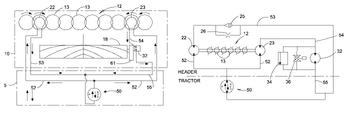
  • FIG. 2 is a plan diagram of one embodiment of a hydraulic circuit used in the present invention.
  • FIG. 3 is a schematic diagram of an alternate embodiment of the hydraulic circuit of the present invention.
  • any reference herein to the terms “left” or “right” are used as a matter of mere convenience, and are determined by standing at the rear of the machine facing in its normal direction of travel. Likewise, “forward” and “rearward” are determined by the normal direction of travel. “Upward” and “downward” orientations are relative to the ground or operating surface as are any references to “horizontal” or “vertical” planes.
  • a typical mower-conditioner header 10 is presented.
  • the header 10 is provided with a crop cutting mechanism 12 , also referred to as a cutterbar, having a plurality of transversely spaced disc cutter members 13 operable to sever standing crop material by an impact action.
  • the individual disc cutter members are interconnected by a driveline to coordinate the rotational position of each cutter mechanism thereby preventing contact between the knives of adjacent cutting members.
  • a conditioning mechanism 14 is mounted in the header 10 rearwardly of the cutterbar 12 to receive and condition crop material severed by the cutterbar.
  • Header 10 may be connected to and propelled by a tractor 5 specifically adapted for use with such headers, commonly referred to as a self-propelled windrower, or the elements of header 10 may be incorporated into a mower-conditioner implement for propulsion by a general purpose agricultural tractor.
  • the description herein is based upon a mower-conditioner header typical of an agricultural windrower. Those skilled in the art will recognize the usefulness of the instant invention on other mower-conditioner platforms.
  • U.S. Pat. No. 5,778,647 issued to McLean et al., the descriptive portions thereof being incorporated herein by reference.
  • the conditioning mechanism 14 includes a pair of cooperable, generally vertically spaced apart transverse conditioner rolls 18 operable to condition severed crop material passing therebetween.
  • Each roll 18 is rotatably supported adjacent opposing sides of the header 10 . Rotation of the rolls 18 is coordinated for counter-rotational movement by a conditioner gearbox 61 , usually connected at one end of the rolls.
  • the preferred embodiment of the conditioner roll construction shown in FIG. 1 includes an intermeshing lug design on the roll surfaces.
  • FIG. 2 wherein a diagram of header 10 shows the cutterbar 12 comprising a plurality of disc cutter members 13 .
  • the individual cutting members are linked to coordinate the rotational position of the cutting knives of adjacent members and prevent contact between knives.
  • the cutterbar 12 is powered by a pair of drivers 22 , 23 , each connected by a drive shaft 21 or similar torque transfer mechanism to an individual disc cutter member.
  • the first and second cutterbar drivers 22 , 23 are typically directly coupled to the disc cutters; no reduction gearboxes are usually employed in order to reduce complexity of the cutterbar drive.
  • the first and second cutterbar drivers 22 , 23 are typically positioned proximate to the outboard ends of the header to equalize the torque distribution along the length of the cutterbar.
  • cutterbar drivers 22 , 23 are hydraulic motors powered by a hydraulic power system 50 on the tractor 5 conveying a flow of pressurized hydraulic fluid through hydraulic supply 52 and return 53 , 54 , 55 lines. It is typical for the two cutterbar drivers 22 , 23 to be hydraulically connected to the hydraulic power system 50 using parallel hydraulic circuits.
  • Cutterbar hydraulic drive systems, including hydraulic drivers (motors) on agricultural harvesters are well known and not discussed in further detail herein.
  • Known conditioner drive mechanisms generally connect mechanical drive to one of the cutterbar hydraulic drivers to convey power to a conditioner gearbox 61 .
  • a separate conditioner hydraulic driver 32 is provided to power the conditioner gearbox 61 and connected conditioner rolls 18 and replacing the comparatively bulky mechanical drivetrain extending from the cutterbar driver to the conditioner gearbox, yet still requiring a single hydraulic circuit to provide motive power to the header components.
  • Conditioner driver 32 is hydraulically connected to the hydraulic circuit for one of the hydraulic cutterbar drivers so that the conditioner driver 32 operates when hydraulic flow is provided to the cutterbar driver.
  • the speed relationship between the disc cutter members 13 and the conditioner rolls 18 is established and managed using the conditioner gearbox 61 ratio and the hydraulic driver displacements.
  • the hydraulic circuit is shown to further comprise a check valve 25 with an orifice 26 connected in parallel positioned in the return flow circuit 53 for one of the cutterbar drivers and a relief valve 34 connected in parallel with the conditioner driver 32 .
  • the check valve 25 and orifice 26 are connected in the return circuit 53 for the first cutterbar driver 22 , the driver hydraulic circuit not directed through the conditioner driver 32 . This configuration prevents damage to the hydraulic circuit in the event the conditioner mechanism becomes clogged with crop material. As the conditioner mechanism jams, the conditioner driver 32 stops and blocks hydraulic fluid flow through return leg 54 .
  • first cutterbar driver 22 drives second cutterbar driver 23 through the disc cutter members, effectively operating second cutterbar driver 23 as a pump.
  • the hydraulic return line 54 between second cutterbar driver 23 and the conditioner driver 32 becomes quickly overpressurized.
  • Relief valve 34 prevents damage by allowing the highly pressurized hydraulic fluid to bypass the jammed conditioner driver 32 and be returned to the tractor hydraulic system 50 .
  • Check valve 25 and bypass orifice 26 restrict the flow of hydraulic fluid through first cutterbar driver 22 when the flow direction is reversed (by reversing flow from the tractor hydraulic system 50 ) to move the conditioner mechanism in reverse and clear the jam.
  • variable flow diverter valve 36 which allows the flow of fluid through conditioner driver 32 to be adjusted.
  • the diverter valve may be used to adjust the bypass flow around the driver 32 .
  • the relative speed between the curretbar drivers 22 , 23 and the conditioner driver 32 may be adjusted thereby enabling an optimum conditioner speed for the crop conditions to be easily obtained.
  • Such adjustment may be performed during operation of the harvester instead of requiring changes to driveline components, such as pulleys.
  • Similar conditioner mechanism speed adjustment may be obtained by selecting a variable displacement hydraulic motor for use as conditioner driver 32 .

Abstract

A hydraulic driver for powering the conditioner mechanism on an agricultural mower-conditioner, the hydraulic driver being powered by the same hydraulic power circuit that powers the cutting mechanism, but which includes controls for varying the speed and/or direction of rotation of the conditioner mechanism independent from the speed of the cutting mechanism.

Description

BACKGROUND OF THE INVENTION
The present invention relates generally to agricultural mower-conditioner drive components, and more particularly relates to a variable-speed hydraulic drive apparatus for the conditioner rolls in an agricultural mower-conditioner.
Windrower mower-conditioner combinations are well known and typically comprise a cutting mechanism, a conditioning unit, and one or more deflectors to arrange the cut and conditioned crop material into a windrow. The windrower mower-conditioner combination is generally a self-propelled unit, but may also be configured to be propelled by a separate tractor. Typically, a standing crop is cut by a sickle bar or a rotating disc cutting mechanism disposed along a leading edge of the combination. The severed crop material is then directed to a conditioner unit that processes the crop for faster drying. The conditioner unit may comprise a pair of intermeshing rolls that crush the crop material passing therebetween, or a flail that breaks and scratches the crop through impact. For background information on the structure and operation of some typical disc mower-conditioners, reference is made to U.S. Pat. No. 5,778,647, issued to McLean et al., the descriptive portions thereof being incorporated herein by reference.
Disc mower-conditioners normally include one or more hydraulic motors to drive the cutting mechanism. In a disc cutter, the hydraulic motors operate at the same speed as the discs eliminating the need for reduction gearboxes between the hydraulic motors and the cutting discs. It is typical to provide an additional output driven by the hydraulic motor, but which includes a reduction gearbox for driving the conditioner rolls. This approach requires a driveline between the hydraulic drive gearbox output shaft and the conditioner rolls. Furthermore, this approach fixes the relative rotational speeds of the disc cutters and the conditioner rolls through the reduction gearbox and does not allow for independent variations in conditioner roll speed.
Obtaining the most efficient crop conditioning performance requires proper matching of the conditioner mechanism speed to the specific crop conditions. Improper conditioner mechanism speed can have an adverse affect on the way in which crop is fed into the conditioner rolls, the configuration of the resultant windrows, fuel economy, and even the condition of the crop, wherein excessive conditioner roll speed tends to excessively damage the crop material. Varying the conditioner mechanism speed in typical mower-conditioner drives requires changing drive pulleys to alter the drive ratio between the hydraulically-driven gearbox output and the conditioner rolls, an adjustment that cannot easily be performed during operation.
It would be advantageous to have a hydraulic drive for the conditioner mechanism in an agricultural mower-conditioner to reduce the cutting mechanism and conditioner mechanism drivetrain complexity. Further advantages would be realized by providing separate hydraulic drives for the cutting and conditioner mechanism that would allow variation in the relative speed of the two mechanisms thereby enabling each to be individually optimized.
SUMMARY OF THE INVENTION
Accordingly, the present invention, in any of the embodiments described herein, may provide one or more of the following advantages:
It is an object of the present invention to provide a hydraulic motor for driving the conditioner mechanism on an agricultural mower-conditioner in addition to the hydraulic motor used to drive the cutting mechanism.
It is a further object of the present invention to eliminate the need for a mechanical drive mechanism for delivering power from a cutting mechanism drive apparatus to the conditioner mechanism.
It is a further object of the present invention to provide separate hydraulic drivers for the cutting and the conditioning mechanisms on an agricultural mower conditioner that may utilize existing hydraulic power supplies on the machine.
It is a still further object of the present invention to provide at least one hydraulic drive apparatus for the conditioner mechanism on an agricultural mower-conditioner that utilizes existing hydraulic power supplies on the machine, but provides a means of control that is separate from the control of hydraulic drivers for the cutting mechanism.
It is a still further object of the present invention to provide a hydraulic drive apparatus for the conditioner device of an agricultural mower-conditioner that enables the conditioner mechanism to be operated independently from the cutting mechanism thereby enabling the conditioner mechanism to be stopped and/or reversed to clear jammed materials without affecting operation of the cutting mechanism.
It is a still further object of the present invention to provide a hydraulic drive for a conditioner mechanism that is durable in construction, inexpensive of manufacture, carefree of maintenance, easily assembled, and simple and effective to use.
These and other objects are achieved in accordance with the instant invention by providing a hydraulic driver for powering the conditioner mechanism on an agricultural mower-conditioner, the hydraulic driver being powered by the same hydraulic power circuit that powers the cutting mechanism, but which includes controls for varying the speed and/or direction of rotation of the conditioner mechanism independent from the speed of the cutting mechanism.
BRIEF DESCRIPTION OF THE DRAWINGS
The advantages of this invention will be apparent upon consideration of the following detailed disclosure of the invention, especially when taken in conjunction with the accompanying drawings wherein:
FIG. 1 is a forward perspective view of a mower-conditioner header of the type on which the present invention is useful;
FIG. 2 is a plan diagram of one embodiment of a hydraulic circuit used in the present invention; and
FIG. 3 is a schematic diagram of an alternate embodiment of the hydraulic circuit of the present invention.
DESCRIPTION OF THE PREFERRED EMBODIMENT(S)
Many of the fastening, connection, processes and other means and components utilized in this invention are widely known and used in the field of the invention described, and their exact nature or type is not necessary for an understanding and use of the invention by a person skilled in the art, and they will not therefore be discussed in significant detail. Also, any reference herein to the terms “left” or “right” are used as a matter of mere convenience, and are determined by standing at the rear of the machine facing in its normal direction of travel. Likewise, “forward” and “rearward” are determined by the normal direction of travel. “Upward” and “downward” orientations are relative to the ground or operating surface as are any references to “horizontal” or “vertical” planes. Furthermore, the various components shown or described herein for any specific application of this invention can be varied or altered as anticipated by this invention and the practice of a specific application of any element may already be widely known or used in the art by persons skilled in the art and each will likewise not therefore be discussed in significant detail. When referring to the figures, like parts are numbered the same in all of the figures.
Referring now to FIG. 1, a typical mower-conditioner header 10 is presented. The header 10 is provided with a crop cutting mechanism 12, also referred to as a cutterbar, having a plurality of transversely spaced disc cutter members 13 operable to sever standing crop material by an impact action. The individual disc cutter members are interconnected by a driveline to coordinate the rotational position of each cutter mechanism thereby preventing contact between the knives of adjacent cutting members. A conditioning mechanism 14 is mounted in the header 10 rearwardly of the cutterbar 12 to receive and condition crop material severed by the cutterbar. Header 10 may be connected to and propelled by a tractor 5 specifically adapted for use with such headers, commonly referred to as a self-propelled windrower, or the elements of header 10 may be incorporated into a mower-conditioner implement for propulsion by a general purpose agricultural tractor. The description herein is based upon a mower-conditioner header typical of an agricultural windrower. Those skilled in the art will recognize the usefulness of the instant invention on other mower-conditioner platforms. For background information on the structure and operation of an exemplar rotary disc cutterbar, reference is made to U.S. Pat. No. 5,778,647, issued to McLean et al., the descriptive portions thereof being incorporated herein by reference.
The conditioning mechanism 14 includes a pair of cooperable, generally vertically spaced apart transverse conditioner rolls 18 operable to condition severed crop material passing therebetween. Each roll 18 is rotatably supported adjacent opposing sides of the header 10. Rotation of the rolls 18 is coordinated for counter-rotational movement by a conditioner gearbox 61, usually connected at one end of the rolls. The preferred embodiment of the conditioner roll construction shown in FIG. 1 includes an intermeshing lug design on the roll surfaces.
Now referring to FIG. 2, wherein a diagram of header 10 shows the cutterbar 12 comprising a plurality of disc cutter members 13. The individual cutting members are linked to coordinate the rotational position of the cutting knives of adjacent members and prevent contact between knives. The cutterbar 12 is powered by a pair of drivers 22, 23, each connected by a drive shaft 21 or similar torque transfer mechanism to an individual disc cutter member. The first and second cutterbar drivers 22, 23 are typically directly coupled to the disc cutters; no reduction gearboxes are usually employed in order to reduce complexity of the cutterbar drive. The first and second cutterbar drivers 22, 23 are typically positioned proximate to the outboard ends of the header to equalize the torque distribution along the length of the cutterbar. In the embodiment shown, cutterbar drivers 22, 23 are hydraulic motors powered by a hydraulic power system 50 on the tractor 5 conveying a flow of pressurized hydraulic fluid through hydraulic supply 52 and return 53, 54, 55 lines. It is typical for the two cutterbar drivers 22, 23 to be hydraulically connected to the hydraulic power system 50 using parallel hydraulic circuits. Cutterbar hydraulic drive systems, including hydraulic drivers (motors) on agricultural harvesters are well known and not discussed in further detail herein.
Known conditioner drive mechanisms generally connect mechanical drive to one of the cutterbar hydraulic drivers to convey power to a conditioner gearbox 61. In the present invention, a separate conditioner hydraulic driver 32 is provided to power the conditioner gearbox 61 and connected conditioner rolls 18 and replacing the comparatively bulky mechanical drivetrain extending from the cutterbar driver to the conditioner gearbox, yet still requiring a single hydraulic circuit to provide motive power to the header components. Conditioner driver 32 is hydraulically connected to the hydraulic circuit for one of the hydraulic cutterbar drivers so that the conditioner driver 32 operates when hydraulic flow is provided to the cutterbar driver. The speed relationship between the disc cutter members 13 and the conditioner rolls 18 is established and managed using the conditioner gearbox 61 ratio and the hydraulic driver displacements.
Now referring to FIG. 3 with reference to FIG. 2, the hydraulic circuit is shown to further comprise a check valve 25 with an orifice 26 connected in parallel positioned in the return flow circuit 53 for one of the cutterbar drivers and a relief valve 34 connected in parallel with the conditioner driver 32. In the embodiment shown, the check valve 25 and orifice 26 are connected in the return circuit 53 for the first cutterbar driver 22, the driver hydraulic circuit not directed through the conditioner driver 32. This configuration prevents damage to the hydraulic circuit in the event the conditioner mechanism becomes clogged with crop material. As the conditioner mechanism jams, the conditioner driver 32 stops and blocks hydraulic fluid flow through return leg 54. However, since the individual disc cutter members are mechanically interconnected, first cutterbar driver 22 drives second cutterbar driver 23 through the disc cutter members, effectively operating second cutterbar driver 23 as a pump. With the conditioner driver 32 blocked, the hydraulic return line 54 between second cutterbar driver 23 and the conditioner driver 32 becomes quickly overpressurized. Relief valve 34 prevents damage by allowing the highly pressurized hydraulic fluid to bypass the jammed conditioner driver 32 and be returned to the tractor hydraulic system 50. Check valve 25 and bypass orifice 26 restrict the flow of hydraulic fluid through first cutterbar driver 22 when the flow direction is reversed (by reversing flow from the tractor hydraulic system 50) to move the conditioner mechanism in reverse and clear the jam.
Also shown in FIG. 3 is a variable flow diverter valve 36 which allows the flow of fluid through conditioner driver 32 to be adjusted. As shown in FIG. 3, the diverter valve may be used to adjust the bypass flow around the driver 32. By incorporating this element into the hydraulic circuit, the relative speed between the curretbar drivers 22, 23 and the conditioner driver 32 may be adjusted thereby enabling an optimum conditioner speed for the crop conditions to be easily obtained. Such adjustment may be performed during operation of the harvester instead of requiring changes to driveline components, such as pulleys. Similar conditioner mechanism speed adjustment may be obtained by selecting a variable displacement hydraulic motor for use as conditioner driver 32.
Naturally, the invention is not limited to the foregoing embodiments, but it can also be modified in many ways without departing from the basic concepts. It will be understood that changes in the details, materials, steps and arrangements of parts which have been described and illustrated to explain the nature of the invention will occur to and may be made by those skilled in the art upon a reading of this disclosure within the principles and scope of the invention. The foregoing description illustrates the preferred embodiment of the invention; however, concepts, as based upon the description, may be employed in other embodiments without departing from the scope of the invention.

Claims (19)

1. A drive apparatus for a mower-conditioner mechanism in an agricultural harvester, the harvester having a tractor for propelling the mechanism across a field of standing crop and a hydraulic power supply, the mower conditioner mechanism having a forwardly disposed cutterbar mechanism and a conditioner mechanism having conditioning rolls disposed rearwardly therefrom, the drive apparatus comprising:
a first and second cutterbar driver for providing rotational motive power to the cutterbar mechanism;
a conditioner driver for providing rotational motive power to the conditioning rolls; and
a hydraulic fluid circuit for conveying a flow of pressurized hydraulic fluid from the hydraulic power system through said at least one cutterbar driver and said conditioner driver, said at least one cutterbar driver and said conditioner driver being serially connected in said hydraulic fluid circuit, said first and second cutterbar drivers being connected to said fluid circuit in a parallel arrangement and said conditioner driver is connected in series with said first cutterbar driver.
2. The drive apparatus of claim 1, wherein said first and second cutterbar drivers are mechanically connected through the cutterbar mechanism.
3. The drive apparatus of claim 1, further comprising a pressure relief device for directing said flow of hydraulic fluid to bypass said conditioner driver when said conditioner driver stalls due to a clog of crop material in the conditioning rolls thereby preventing damage to said fluid circuit and the hydraulic power system.
4. The drive apparatus of claim 3, wherein said conditioner driver is configured for operation in a forward direction and an opposing reverse direction, and hydraulic fluid circuit is configured for providing pressurized hydraulic fluid to said conditioner driver in a manner to enable selective rotation of said conditioner driver in said forward direction or said reverse direction.
5. The drive apparatus of claim 4, wherein said hydraulic fluid circuit further comprises a bypass loop and a selectively adjustable control valve for diverting a selectively variable portion of said pressurized hydraulic fluid from said conditioner driver thereby enabling variation in the rotational speed of said conditioner driver independent of variation in the flow of the hydraulic fluid in the fluid circuit.
6. The drive apparatus of claim 4, wherein said conditioner driver is a variable displacement hydraulic motor thereby enabling variation in the rotational speed of said conditioner driver independent of variation in the flow of the hydraulic fluid in the fluid circuit.
7. A method for driving a cutter mechanism and a conditioner mechanism in an agricultural windrower, the windrower having a tractor for supporting and propelling a header across a field of standing crop, a hydraulic power supply, the header having a forwardly disposed cutterbar mechanism and the conditioner mechanism having conditioning rolls disposed rearwardly therefrom, the method comprising the steps:
providing a first cutterbar driver and a second cutterbar driver for providing rotational motive power to the cutterbar mechanism;
providing a conditioner driver for providing rotational motive power to the conditioning rolls;
providing a hydraulic fluid circuit for conveying a flow of pressurized hydraulic fluid from the hydraulic power system through the at least one cutterbar driver and the conditioner driver, the at least one cutterbar driver and the conditioner driver being serially connected in said hydraulic fluid circuit;
connecting the first and second cutterbar drivers to said fluid circuit in a parallel arrangement and connecting the conditioner driver in series with the first cutterbar driver whereby the first and second cutterbar drivers provide motive power to the cutterbar mechanism;
engaging the hydraulic power supply and directing the flow of hydraulic fluid through the fluid circuit in a first direction; and
propelling the windrower across a field of standing crop wherein the cutterbar mechanism severs the standing crop from the ground and the conditioner mechanism conditions the severed crop material prior to depositing on the ground in a windrow.
8. The method of claim 7, further comprising the steps of:
wherein the first and second cutterbar drivers are mechanically connected through the cutterbar mechanism.
9. The method of claim 8, further comprising the step of:
providing a pressure relief device for directing the flow of hydraulic fluid to bypass the conditioner driver when the conditioner driver stalls due to a clog of crop material in the conditioning rolls thereby preventing damage to said fluid circuit and the hydraulic power system.
10. The method of claim 9, further comprising the steps of:
providing a conditioner driver configured for operation in a forward direction and an opposing reverse direction,
configuring the hydraulic fluid circuit to provide pressurized hydraulic fluid to the conditioner driver in a manner to enable selective rotation of the conditioner driver in said forward direction or said reverse direction; and
reversing the direction of the conditioner driver in order to clear the conditioning rolls of clogged crop material.
11. The method of claim 10, further comprising the steps of:
providing a bypass loop having a selectively adjustable control valve in the hydraulic fluid circuit for diverting a selectively variable portion of the pressurized hydraulic fluid from the conditioner driver; and
selectively adjusting the control valve to alter the rotational speed of the conditioner driver with respect to the speed of the cutterbar driver in order to optimize operation of the conditioner mechanism.
12. The method of claim 10, further comprising the steps of:
providing a variable displacement hydraulic motor for the conditioner driver; and
selectively varying the displacement of the hydraulic motor thereby varying the rotational speed of the conditioner driver independent of the flow of the hydraulic fluid in the fluid circuit and the speed of the cutterbar driver.
13. In an agricultural windrower having a tractor for supporting and propelling a header across a field of standing crop, the tractor having a hydraulic power supply for conveying motive power to the header, the header having a forwardly disposed cutting mechanism and a rearwardly disposed conditioner mechanism having conditioning rolls, the improvement in a drive mechanism for the cutting and conditioner mechanisms comprising:
at least one cutterbar driver for providing rotational motive power to the cutterbar mechanism;
a conditioner driver for providing rotational motive power to the conditioning rolls; and
a hydraulic fluid circuit for conveying a flow of pressurized hydraulic fluid from the hydraulic power system through said at least one cutterbar driver and said conditioner driver, said at least one cutterbar driver and said conditioner driver being serially connected in said hydraulic fluid circuit, the hydraulic fluid circuit further having in parallel with the conditioner driver a bypass loop and a selectively adjustable control valve for diverting a selectively variable portion of said pressurized hydraulic fluid from said conditioner driver thereby enabling variation in the rotational speed of said conditioner driver independent of variation in the flow of the hydraulic fluid though the cutterbar driver.
14. The improvement of claim 13, further comprising a first cutterbar driver and a second cutterbar driver, said first and second cutterbar drivers being connected to said fluid circuit in a parallel arrangement and said conditioner driver is connected in series with said first cutterbar driver.
15. The improvement of claim 14, further comprising a pressure relief device for directing said flow of hydraulic fluid to bypass said conditioner driver when said conditioner driver stalls due to a clog of crop material in the conditioning rolls thereby preventing damage to said fluid circuit and the hydraulic power system.
16. The improvement of claim 15, wherein said conditioner driver is configured for operation in a forward direction and an opposing reverse direction, and hydraulic fluid circuit is configured for providing pressurized hydraulic fluid to said conditioner driver in a manner to enable selective rotation of said conditioner driver in said forward direction or said reverse direction.
17. The improvement of claim 16, wherein said conditioner driver is a variable displacement hydraulic motor thereby enabling variation in the rotational speed of said conditioner driver independent of variation in the flow of the hydraulic fluid in the fluid circuit.
18. A drive apparatus for a mower-conditioner mechanism in an agricultural harvester, the mower conditioner mechanism having a forwardly disposed cutterbar mechanism and a conditioner mechanism having conditioner rolls disposed rearwardly therefrom, the drive apparatus comprising:
a cutterbar driver for providing rotational motive power to the cutterbar mechanism;
a conditioner driver for providing rotational motive power to the conditioner rolls; and
a hydraulic fluid circuit for conveying a flow of pressurized hydraulic fluid from a hydraulic power system through said at least one cutterbar driver and said conditioner driver, said at least one cutterbar driver and said conditioner driver being serially connected in said hydraulic fluid circuit; the hydraulic fluid circuit further having a bypass loop and a selectively adjustable control valve for diverting a selectively variable portion of said pressurized hydraulic fluid from said conditioner driver thereby enabling variation in the rotational speed of said conditioner driver independent of variation in the flow of the hydraulic fluid through the cutterbar driver.
19. The drive apparatus of claim 18, wherein said conditioner driver is configured for operation in a forward direction and an opposing reverse direction, and hydraulic fluid circuit is a closed circuit configured for providing pressurized hydraulic fluid to said conditioner driver in a manner to enable selective rotation of said conditioner driver in said forward direction or said reverse direction.
US12/416,510 2009-04-01 2009-04-01 Variable speed hydraulic conditioner drive Expired - Fee Related US7730701B1 (en)

Priority Applications (1)

Application Number Priority Date Filing Date Title
US12/416,510 US7730701B1 (en) 2009-04-01 2009-04-01 Variable speed hydraulic conditioner drive

Applications Claiming Priority (1)

Application Number Priority Date Filing Date Title
US12/416,510 US7730701B1 (en) 2009-04-01 2009-04-01 Variable speed hydraulic conditioner drive

Publications (1)

Publication Number Publication Date
US7730701B1 true US7730701B1 (en) 2010-06-08

Family

ID=42226780

Family Applications (1)

Application Number Title Priority Date Filing Date
US12/416,510 Expired - Fee Related US7730701B1 (en) 2009-04-01 2009-04-01 Variable speed hydraulic conditioner drive

Country Status (1)

Country Link
US (1) US7730701B1 (en)

Cited By (8)

* Cited by examiner, † Cited by third party
Publication number Priority date Publication date Assignee Title
WO2012097114A1 (en) * 2011-01-12 2012-07-19 Agco Corporation Auxiliary drive motor for hay conditioner on a windrower header
US8490371B2 (en) * 2011-12-20 2013-07-23 Cnh Canada, Ltd. Modular electric disc cutterbar and controller
US8833046B2 (en) * 2012-10-15 2014-09-16 Neil Gordon Barnett Rotary disk crop harvesting header with rearwardly shifted top conditioning roll and lower rear deflector
US9179600B2 (en) 2012-11-27 2015-11-10 Deere & Company Mower-conditioner header speed control based on forward travel speed
GB2560998A (en) * 2017-03-31 2018-10-03 Kverneland Group Kerteminde As Continuously variable conditioner speed
US11051453B2 (en) * 2018-11-14 2021-07-06 Cnh Industrial America Llc Reel drive assembly for an agricultural header
US20220232775A1 (en) * 2021-01-22 2022-07-28 Deere & Company Work vehicle having a cutter assembly with a pre-loaded gear train and method of controlling same
US11503764B2 (en) 2019-01-28 2022-11-22 Cnh Industrial America Llc Hydraulic sickle knife drive on a combine header

Citations (17)

* Cited by examiner, † Cited by third party
Publication number Priority date Publication date Assignee Title
US4585042A (en) * 1982-09-30 1986-04-29 Hutson James Henry Log debarker
US5778644A (en) 1996-08-09 1998-07-14 Deere & Company Crop harvesting platform having a reversible drive for the reel, cutterbar center-feed augers and conditioner rolls
US5791128A (en) * 1996-07-05 1998-08-11 Macdon Industries Ltd. Reversible hydraulic drive apparatus
US6247296B1 (en) * 1999-04-23 2001-06-19 Deere & Comapny Drive arrangement for the crop conveying and/or processing mechanism of a harvesting machine
US6425232B1 (en) 1999-12-27 2002-07-30 New Holland North America, Inc. Crop processor roll arrangement for a forage harvester
US6430905B2 (en) 2000-03-14 2002-08-13 Claas Selbstfahrende Erntemaschinen Gmbh Hydraulic drive for a feeder mechanism in a material pick-up device
US6659378B2 (en) 2002-03-13 2003-12-09 Guiseppe Di Anna Field shredder for pruned branches
US20040065070A1 (en) 2002-10-02 2004-04-08 Dunn James Thomas Crop conditioner roller drive
US6718744B2 (en) 2001-06-19 2004-04-13 Deere & Company Drive arrangement for mower-conditioner equipped with a rotary disc cutter bar
US6775966B2 (en) 2001-12-18 2004-08-17 New Holland North America, Inc. Integrated combine reel drive system
US6895734B2 (en) * 2001-01-22 2005-05-24 Cnh America Llc Agricultural harvesting machines and front attachments therefor
US7036296B2 (en) 2004-02-20 2006-05-02 Maschinenfabrik Kemper Gmbh & Co Kg Variable speed drive for oblique feeding drums
US7140169B2 (en) 2000-03-06 2006-11-28 Cnh America Llc Feeder controls for a forage harvester
US20080295478A1 (en) * 2007-06-04 2008-12-04 Crary Industries, Inc. Synchronous drive for split sickle bars on harvester header
US7467505B2 (en) * 2005-10-25 2008-12-23 Macdon Industries Ltd. Crop harvesting header with drive reversal
US7497069B2 (en) * 2006-11-03 2009-03-03 Macdon Industries Ltd. Crop harvesting header with reversible drive to the sickle knife
US7640718B2 (en) * 2006-05-30 2010-01-05 Claas Saulgau Gmbh Attachment for harvesting stalk-like goods where each cutting and conveying element is controlled individually

Patent Citations (17)

* Cited by examiner, † Cited by third party
Publication number Priority date Publication date Assignee Title
US4585042A (en) * 1982-09-30 1986-04-29 Hutson James Henry Log debarker
US5791128A (en) * 1996-07-05 1998-08-11 Macdon Industries Ltd. Reversible hydraulic drive apparatus
US5778644A (en) 1996-08-09 1998-07-14 Deere & Company Crop harvesting platform having a reversible drive for the reel, cutterbar center-feed augers and conditioner rolls
US6247296B1 (en) * 1999-04-23 2001-06-19 Deere & Comapny Drive arrangement for the crop conveying and/or processing mechanism of a harvesting machine
US6425232B1 (en) 1999-12-27 2002-07-30 New Holland North America, Inc. Crop processor roll arrangement for a forage harvester
US7140169B2 (en) 2000-03-06 2006-11-28 Cnh America Llc Feeder controls for a forage harvester
US6430905B2 (en) 2000-03-14 2002-08-13 Claas Selbstfahrende Erntemaschinen Gmbh Hydraulic drive for a feeder mechanism in a material pick-up device
US6895734B2 (en) * 2001-01-22 2005-05-24 Cnh America Llc Agricultural harvesting machines and front attachments therefor
US6718744B2 (en) 2001-06-19 2004-04-13 Deere & Company Drive arrangement for mower-conditioner equipped with a rotary disc cutter bar
US6775966B2 (en) 2001-12-18 2004-08-17 New Holland North America, Inc. Integrated combine reel drive system
US6659378B2 (en) 2002-03-13 2003-12-09 Guiseppe Di Anna Field shredder for pruned branches
US20040065070A1 (en) 2002-10-02 2004-04-08 Dunn James Thomas Crop conditioner roller drive
US7036296B2 (en) 2004-02-20 2006-05-02 Maschinenfabrik Kemper Gmbh & Co Kg Variable speed drive for oblique feeding drums
US7467505B2 (en) * 2005-10-25 2008-12-23 Macdon Industries Ltd. Crop harvesting header with drive reversal
US7640718B2 (en) * 2006-05-30 2010-01-05 Claas Saulgau Gmbh Attachment for harvesting stalk-like goods where each cutting and conveying element is controlled individually
US7497069B2 (en) * 2006-11-03 2009-03-03 Macdon Industries Ltd. Crop harvesting header with reversible drive to the sickle knife
US20080295478A1 (en) * 2007-06-04 2008-12-04 Crary Industries, Inc. Synchronous drive for split sickle bars on harvester header

Cited By (14)

* Cited by examiner, † Cited by third party
Publication number Priority date Publication date Assignee Title
WO2012097114A1 (en) * 2011-01-12 2012-07-19 Agco Corporation Auxiliary drive motor for hay conditioner on a windrower header
US8656694B2 (en) 2011-01-12 2014-02-25 Agco Corporation Auxiliary drive motor for hay conditioner on a windrower header
US8490371B2 (en) * 2011-12-20 2013-07-23 Cnh Canada, Ltd. Modular electric disc cutterbar and controller
US8931245B2 (en) * 2011-12-20 2015-01-13 Cnh Industrial Canada, Ltd. Modular electric disc cutterbar and controller
US8833046B2 (en) * 2012-10-15 2014-09-16 Neil Gordon Barnett Rotary disk crop harvesting header with rearwardly shifted top conditioning roll and lower rear deflector
US10080328B2 (en) 2012-11-27 2018-09-25 Deere & Company Mower-conditioner header speed control based on forward travel speed
US9179600B2 (en) 2012-11-27 2015-11-10 Deere & Company Mower-conditioner header speed control based on forward travel speed
GB2560998A (en) * 2017-03-31 2018-10-03 Kverneland Group Kerteminde As Continuously variable conditioner speed
US11234369B2 (en) 2017-03-31 2022-02-01 Kverneland Group Kerteminde As Mower-conditioner with a variable speed ratio
AU2017406396B2 (en) * 2017-03-31 2022-09-01 Kverneland Group Kerteminde As Mower-conditioner
US11051453B2 (en) * 2018-11-14 2021-07-06 Cnh Industrial America Llc Reel drive assembly for an agricultural header
US11503764B2 (en) 2019-01-28 2022-11-22 Cnh Industrial America Llc Hydraulic sickle knife drive on a combine header
US20220232775A1 (en) * 2021-01-22 2022-07-28 Deere & Company Work vehicle having a cutter assembly with a pre-loaded gear train and method of controlling same
US11882792B2 (en) * 2021-01-22 2024-01-30 Deere & Company Work vehicle having a cutter assembly with a pre-loaded gear train and method of controlling same

Similar Documents

Publication Publication Date Title
US7730701B1 (en) Variable speed hydraulic conditioner drive
US6247296B1 (en) Drive arrangement for the crop conveying and/or processing mechanism of a harvesting machine
US10080328B2 (en) Mower-conditioner header speed control based on forward travel speed
US7497069B2 (en) Crop harvesting header with reversible drive to the sickle knife
EP2995188B1 (en) Power takeoff drive assembly for a corn header of an agricultural harvester
USRE40614E1 (en) Rotary cutter bed harvester with non-auger conveying means for outboard cutters
US8056307B2 (en) Mower cutterbar
US8656694B2 (en) Auxiliary drive motor for hay conditioner on a windrower header
CA2609744C (en) Crop harvesting header with reversible drive to the sickle knife
US4304086A (en) Lawn mower attachment for small tractors
EP1862057A1 (en) Attachment device for harvesting stalk crops
US7140169B2 (en) Feeder controls for a forage harvester
AU6836094A (en) Harvester with hydraulically driven, flow-compensated rotary cutter bed
US10477767B2 (en) Draper platform with removable central roller baffle
CA2323948C (en) Mowing implement
BE1021620B1 (en) DRIVE SYSTEM FOR A MINING MACHINE
CA2935230C (en) Method and apparatus for harvesting crop material
EP3917306A1 (en) Hydraulic sickle knife drive on a combine header
JP3725529B2 (en) Sugar cane harvester hydraulic drive
US3945175A (en) Variable speed feed roll drive mechanism for forage harvesters
US7036296B2 (en) Variable speed drive for oblique feeding drums
US7823372B1 (en) Skewed roller conveyor for double windrow attachment
JP3577738B2 (en) Combine transmission mechanism
EP1183933A1 (en) Turf-care apparatus with hydraulic power transmission
JP2001078542A (en) Combine harvester

Legal Events

Date Code Title Description
AS Assignment

Owner name: CNH AMERICA, LLC,PENNSYLVANIA

Free format text: ASSIGNMENT OF ASSIGNORS INTEREST;ASSIGNORS:EHRHART, PHILIP J.;WHITENIGHT, D. RUSSELL;HARRIS, LUKE J.;SIGNING DATES FROM 20090331 TO 20090401;REEL/FRAME:022485/0555

STCF Information on status: patent grant

Free format text: PATENTED CASE

AS Assignment

Owner name: BLUE LEAF I.P., INC., DELAWARE

Free format text: ASSIGNMENT OF ASSIGNORS INTEREST;ASSIGNOR:CNH AMERICA LLC;REEL/FRAME:025105/0143

Effective date: 20101007

FPAY Fee payment

Year of fee payment: 4

MAFP Maintenance fee payment

Free format text: PAYMENT OF MAINTENANCE FEE, 8TH YEAR, LARGE ENTITY (ORIGINAL EVENT CODE: M1552)

Year of fee payment: 8

FEPP Fee payment procedure

Free format text: MAINTENANCE FEE REMINDER MAILED (ORIGINAL EVENT CODE: REM.); ENTITY STATUS OF PATENT OWNER: LARGE ENTITY

LAPS Lapse for failure to pay maintenance fees

Free format text: PATENT EXPIRED FOR FAILURE TO PAY MAINTENANCE FEES (ORIGINAL EVENT CODE: EXP.); ENTITY STATUS OF PATENT OWNER: LARGE ENTITY

STCH Information on status: patent discontinuation

Free format text: PATENT EXPIRED DUE TO NONPAYMENT OF MAINTENANCE FEES UNDER 37 CFR 1.362

FP Lapsed due to failure to pay maintenance fee

Effective date: 20220608