EP1862020B1 - Konfiguration von fehler- und erfassungstimeouts zur wiederherstellung nach fehlern in hierarchischen mesh-netzwerken - Google Patents
Konfiguration von fehler- und erfassungstimeouts zur wiederherstellung nach fehlern in hierarchischen mesh-netzwerken Download PDFInfo
- Publication number
- EP1862020B1 EP1862020B1 EP06739466.8A EP06739466A EP1862020B1 EP 1862020 B1 EP1862020 B1 EP 1862020B1 EP 06739466 A EP06739466 A EP 06739466A EP 1862020 B1 EP1862020 B1 EP 1862020B1
- Authority
- EP
- European Patent Office
- Prior art keywords
- routing node
- node
- parent
- routing
- child
- Prior art date
- Legal status (The legal status is an assumption and is not a legal conclusion. Google has not performed a legal analysis and makes no representation as to the accuracy of the status listed.)
- Expired - Lifetime
Links
Images





Classifications
-
- H—ELECTRICITY
- H04—ELECTRIC COMMUNICATION TECHNIQUE
- H04W—WIRELESS COMMUNICATION NETWORKS
- H04W56/00—Synchronisation arrangements
- H04W56/001—Synchronization between nodes
- H04W56/0015—Synchronization between nodes one node acting as a reference for the others
-
- H—ELECTRICITY
- H04—ELECTRIC COMMUNICATION TECHNIQUE
- H04L—TRANSMISSION OF DIGITAL INFORMATION, e.g. TELEGRAPHIC COMMUNICATION
- H04L41/00—Arrangements for maintenance, administration or management of data switching networks, e.g. of packet switching networks
- H04L41/06—Management of faults, events, alarms or notifications
- H04L41/0654—Management of faults, events, alarms or notifications using network fault recovery
- H04L41/0663—Performing the actions predefined by failover planning, e.g. switching to standby network elements
-
- H—ELECTRICITY
- H04—ELECTRIC COMMUNICATION TECHNIQUE
- H04L—TRANSMISSION OF DIGITAL INFORMATION, e.g. TELEGRAPHIC COMMUNICATION
- H04L43/00—Arrangements for monitoring or testing data switching networks
-
- H—ELECTRICITY
- H04—ELECTRIC COMMUNICATION TECHNIQUE
- H04L—TRANSMISSION OF DIGITAL INFORMATION, e.g. TELEGRAPHIC COMMUNICATION
- H04L45/00—Routing or path finding of packets in data switching networks
- H04L45/02—Topology update or discovery
- H04L45/04—Interdomain routing, e.g. hierarchical routing
-
- H—ELECTRICITY
- H04—ELECTRIC COMMUNICATION TECHNIQUE
- H04L—TRANSMISSION OF DIGITAL INFORMATION, e.g. TELEGRAPHIC COMMUNICATION
- H04L45/00—Routing or path finding of packets in data switching networks
- H04L45/48—Routing tree calculation
-
- H—ELECTRICITY
- H04—ELECTRIC COMMUNICATION TECHNIQUE
- H04W—WIRELESS COMMUNICATION NETWORKS
- H04W40/00—Communication routing or communication path finding
- H04W40/24—Connectivity information management, e.g. connectivity discovery or connectivity update
-
- H—ELECTRICITY
- H04—ELECTRIC COMMUNICATION TECHNIQUE
- H04W—WIRELESS COMMUNICATION NETWORKS
- H04W8/00—Network data management
- H04W8/02—Processing of mobility data, e.g. registration information at HLR [Home Location Register] or VLR [Visitor Location Register]; Transfer of mobility data, e.g. between HLR, VLR or external networks
- H04W8/04—Registration at HLR or HSS [Home Subscriber Server]
-
- H—ELECTRICITY
- H04—ELECTRIC COMMUNICATION TECHNIQUE
- H04L—TRANSMISSION OF DIGITAL INFORMATION, e.g. TELEGRAPHIC COMMUNICATION
- H04L12/00—Data switching networks
- H04L12/54—Store-and-forward switching systems
- H04L12/56—Packet switching systems
- H04L12/5601—Transfer mode dependent, e.g. ATM
- H04L2012/5678—Traffic aspects, e.g. arbitration, load balancing, smoothing, buffer management
- H04L2012/5679—Arbitration or scheduling
-
- H—ELECTRICITY
- H04—ELECTRIC COMMUNICATION TECHNIQUE
- H04L—TRANSMISSION OF DIGITAL INFORMATION, e.g. TELEGRAPHIC COMMUNICATION
- H04L41/00—Arrangements for maintenance, administration or management of data switching networks, e.g. of packet switching networks
- H04L41/12—Discovery or management of network topologies
-
- H—ELECTRICITY
- H04—ELECTRIC COMMUNICATION TECHNIQUE
- H04L—TRANSMISSION OF DIGITAL INFORMATION, e.g. TELEGRAPHIC COMMUNICATION
- H04L41/00—Arrangements for maintenance, administration or management of data switching networks, e.g. of packet switching networks
- H04L41/22—Arrangements for maintenance, administration or management of data switching networks, e.g. of packet switching networks comprising specially adapted graphical user interfaces [GUI]
-
- H—ELECTRICITY
- H04—ELECTRIC COMMUNICATION TECHNIQUE
- H04L—TRANSMISSION OF DIGITAL INFORMATION, e.g. TELEGRAPHIC COMMUNICATION
- H04L45/00—Routing or path finding of packets in data switching networks
- H04L45/28—Routing or path finding of packets in data switching networks using route fault recovery
-
- H—ELECTRICITY
- H04—ELECTRIC COMMUNICATION TECHNIQUE
- H04L—TRANSMISSION OF DIGITAL INFORMATION, e.g. TELEGRAPHIC COMMUNICATION
- H04L7/00—Arrangements for synchronising receiver with transmitter
- H04L7/0079—Receiver details
- H04L7/0083—Receiver details taking measures against momentary loss of synchronisation, e.g. inhibiting the synchronisation, using idle words or using redundant clocks
-
- H—ELECTRICITY
- H04—ELECTRIC COMMUNICATION TECHNIQUE
- H04W—WIRELESS COMMUNICATION NETWORKS
- H04W24/00—Supervisory, monitoring or testing arrangements
-
- H—ELECTRICITY
- H04—ELECTRIC COMMUNICATION TECHNIQUE
- H04W—WIRELESS COMMUNICATION NETWORKS
- H04W40/00—Communication routing or communication path finding
-
- H—ELECTRICITY
- H04—ELECTRIC COMMUNICATION TECHNIQUE
- H04W—WIRELESS COMMUNICATION NETWORKS
- H04W72/00—Local resource management
- H04W72/20—Control channels or signalling for resource management
-
- H—ELECTRICITY
- H04—ELECTRIC COMMUNICATION TECHNIQUE
- H04W—WIRELESS COMMUNICATION NETWORKS
- H04W84/00—Network topologies
- H04W84/18—Self-organising networks, e.g. ad-hoc networks or sensor networks
Definitions
- the present invention relates to wireless mesh communication networks and, more particularly, to a failure-acquire timeout mechanism that facilitates recovery from routing node failures in a hierarchical wireless mesh network.
- Wireless mesh communication networks typically consist of a plurality of wireless routing nodes that operate in a peer-to-peer fashion to establish communication paths to one another for the purposes of providing network access to wireless clients or mobile stations.
- Some wireless mesh networks are hierarchical in nature with the routing nodes that bridge wireless traffic onto a wired network at the top of the hierarchy.
- the wireless mesh routing nodes can be one-, two-, or multiple radio systems including omni-directional and/or directional antennas, and systems that provide backhaul traffic over the same mesh hierarchy but over multiple channels.
- the radio unit is used for purposes of acting as an access point to its clients, as well as acting as a backhaul to a parent routing node.
- one implementation can use discovery to determine a potential set of parents.
- the discovery process involves scanning channel and antenna pairs to find suitable parents.
- One technique is to probe, by transmitting a networking packet on the broadcast channel, which is then responded to by suitable parents.
- the time to acquire a new parent is typically very small.
- An acquire packet is transmitted and the receiver is always available on the medium on which it is transmitted, be it a local area network, or on a wireless channel, directional antenna pair.
- the acquire time can be much longer.
- Figure 1 is a functional block diagram that illustrates a hierarchical wireless mesh network according to an implementation of the present invention.
- Figure 2 is a schematic diagram illustrating the logical configuration, according to one implementation of the present invention, of a wireless routing node.
- Figure 3B is a chart showing events, procedure descriptions and data structures associated with the state diagram of Figure 3A .
- Figure 5A is a flow chart diagram that shows processing of a neighbor request packet according to one implementation of the present invention.
- FIGS. 6A and 6B together, provide a flow chart diagram illustrating processing of a neighbor response packet according to one implementation of the present invention.
- Figure 6C illustrates a process flow, according to one implementation of the invention, directed to evaluating adjacency entries
- Figure 8 is a diagram illustrating the data slots and contention slots in a cycle interval according to one implementation of a wireless mesh network.
- Figure 10A illustrates the data and contention slot schedule of a parent routing node in the wireless mesh network illustrated in Figure 9 .
- Figure 12 is a diagram illustrating elements of a data slot according to one implementation of the invention.
- the routing nodes in the mesh network generally include one radio, operating in a first frequency band, and associated wireless communication functionality to communicate with other routing nodes to thereby implement the wireless backbone, as discussed more fully below. All or a subset of the routing nodes, in one implementation, also include an additional radio, operating in a second, non-interfering frequency band, and other wireless communication functionality to establish and maintain wireless connections with mobile stations, such as wireless client 40.
- the backbone radios on the wireless routing nodes may transmit wireless packets between each other using the 802.11a protocol on the 5 GHz band, while the second radio on each wireless node may interact with wireless clients on the 2.4 GHz band (802.11b/g).
- this relation can also be reversed with backhaul traffic using the 802.11b/g frequency band, and client traffic using the 802.11a band.
- Figure 1 also illustrates a channel assignment within a given frequency band between routing nodes according to one possible implementation of the present invention.
- the routing nodes for a given tree and a given hop are set to the same channel.
- the operating channel for upstream data transfer in one implementation, is different than the operating channel used for downstream data transfer.
- wireless transmissions between routing node 1 and routing node 3 occur on channel 1, while routing node 3 communicates with routing node 5 and routing node 6 on channel 2.
- the upstream and downstream channels assigned to a given routing node are non-overlapping channels, while in other implementations they are overlapping channels.
- the channel assignments between routing nodes is statically configured.
- operating channels can be dynamically assigned. However, this channel assignment scheme is not required by the present invention.
- all routing nodes in the mesh network operate on the same channel within the backhaul frequency band.
- each routing node in the mesh network is operative to transmit and receive packets from other routing nodes according to a mesh routing hierarchy.
- Each mesh routing node in one implementation, is further operative to establish and maintain wireless connections to one or more wireless client devices 40.
- Mesh network control system 20, in one implementation, is operative monitor to which routing node each wireless client is associated and route packets destined for the wireless clients to the wireless routing node to which the client is associated.
- FIG. 2 is a schematic diagram illustrating the logical and/or operating components according to one implementation of the present invention.
- the routing node illustrated in Figure 2 includes a wireless backbone interface unit 60 operating in a first frequency band, and a WLAN interface unit 80 operating in a second frequency band.
- a mesh routing node generally comprises routing node control processor 70, wireless backbone interface unit 60, and WLAN interface unit 80.
- the routing node control processor 70, wireless backbone interface unit 60, and WLAN interface unit 80 are operably connected to each other via a system bus.
- Routing node control processor 70 generally refers to the hardware modules (e.g., processor, memory), software modules (e.g., drivers etc.) and data structures (e.g., frame buffers, queues, etc.) that control operation of the routing node.
- routing node control processor 70 generally comprises a processor (e.g., a Central Processing Unit (CPU), etc.), a memory (e.g., RAM, EPROMS, etc.), and a system bus interconnecting the memory, the processor and the network interfaces.
- Routing node control processor 70 may further comprise an operating system and one or more software modules and/or drivers for implementing the functions described herein.
- Routing node control processor 70 controls the operation of wireless backbone interface unit 60 and WLAN interface unit 80, both of which may reside on network cards operably connected to the system bus.
- routing node control processor 70 is operative to control the operation of wireless backbone interface unit 60 to synchronize uplink and downlink transmission with other routing nodes in the mesh network (see Section B, below).
- wireless backbone interface unit 60 in the receive direction, provides wireless frames received at first antenna 85 or second antenna 86 to routing node control processor 70.
- Flag detector 72 in one implementation, is operative to inspect wireless frames received from other routing nodes, and to determine whether the wireless frames should be forwarded along the wireless backbone or to a wireless client associated with the instant routing node via WLAN interface unit 80.
- routing node control processor 70 In response to control signals transmitted by flag detector 72, logical switch 74 transmits the wireless packets along a WLAN path to WLAN interface unit 80, or a wireless backbone path to the upstream or downstream queues 77, 78.
- routing node control processor 70 also includes logical switch 76 that switches between upstream transmit and receive queues 77 and downstream transmit and receive queues 78 depending on the current operational phase or mode. For example, wireless frames received from a parent routing node during the parent slot are buffered in the downstream transmit/receive queues 78 for transmission to a child routing node for transmission in the appropriate child slot.
- the wireless routing node can include more than two directional antennas.
- each backbone radio interface may be operably connected to four directional antennas, whose peak gains are each oriented at 90 degrees to each other.
- each routing node further comprises a neighbor state machine operative to discover and maintain data relating to neighboring routing nodes.
- each node in the wireless mesh network implements a neighbor state machine that is directed to transmitting and receiving neighbor messages from other routing nodes in the wireless mesh.
- the neighbor messages are used by each routing node, in one implementation, to automatically configure and maintain the hierarchical routing configuration across the mesh network.
- the processing of neighbor messages allows for dynamic discovery of routing nodes in the mesh network, facilitates determination of preferred antennas for communicating with neighboring routing nodes, and allows for failure detection and other wireless network conditions and events.
- the neighbor and route management functionality implemented on each node is responsible for one or more of the following tasks: 1) discovering neighboring routing nodes; 2) maintaining a list of attractive neighbor routing nodes as tentative parent routing nodes; 3) selecting a neighbor routing node to act as a parent routing node in the routing system hierarchy; 4) advertising route metrics to neighboring routing nodes; 5) maintaining a list of undesirable neighbor routing nodes.
- the data slotting values can include 1) a "slot early time” indicating an amount of time before a data slot by which a child routing node should begin changing its configuration to operate in that slot (e.g., changing channels, antennas, etc.); 2) a "slot dead time” indicating an amount of unused slot space at end of slot); and 3) a slot duration time.
- the mesh routing information can include: 1) the number of routes to one or more root APs; and 2) for each route: a) the number of hops to the root routing node, b) the unadjusted ease of the routing node (see below), and c) a distance vector of MAC addresses representing the hops in the route.
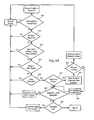
- Figures 3A and 3B set forth the actions, protocol events, and module interfaces associated with a neighbor state machine according to one implementation of the present invention.
- the neighbor state machine implemented on a given routing node can be in one of five states: 1) START, 2) SEEK, 3) SYNC, 4) AUTH, and 5) MAINT.
- the START state occurs when a routing node is powered on or otherwise restarted.
- the adjNull function resets various timers and enters the SEEK state.
- the routing node is a root routing node (e.g., node 30 in Figure 1 )
- the adjNull function sets the neighbor state machine to the MAINT state.
- a routing node attempts to discover its neighbor routing nodes.
- the routing node switching across all available entennas, scans all available operating channels, broadcasting neighbor request packets and listening for neighbor response packets.
- the routing node also populates an adjacency data structure that includes attribute data characterizing the neighbor routing nodes it discovers during the SEEK state.
- Discovered data stored in the adjacency data structure can include the MAC address of the routing node, the signal to noise ratio detected in connection with packets received from the routing node, and the like.
- the routing node in the SEEK state, operates in one frequency channel until adjTimerl2 times out, and then switches to the next operating channel and broadcasts additional neighbor request packets to discover other potential neighbor packets.
- the routing node evaluates the neighbor routing nodes it discovered to identify a potential parent routing node with which to synchronize. If it does not identify a potential parent, the routing node re-enters the START state.
- the transmitting routing node transmits multiple neighbor request packets under the assumption that the neighboring routing nodes will eventually detect some or all the packets and pass the packet(s) up the protocol stack for higher level processing.
- the routing node if the routing node fails to synchronize with the first selected routing node, it adds the routing node to a black list (in one implementation, by setting a flag in the adjacency data structure), deletes the current potential parent from the TP variable, and re-evaluates its discovered neighbors to choose another tentative parent (TP).
- Figure 3A shows, if the routing node fails to identify another tentative parent, it re-enters the START state.
- a successful synchronization causes the routing node to enter the AUTH state.
- the AUTH state is optional.
- the AUTH state is directed to authenticating the security credentials (e.g., a digital signatures, certificates, etc.) of the parent routing node from the child routing node's perspective, as well as the security credentials of the child routing node from the perspective of the child routing node.
- the neighbor state machine sets the tentative parent to the actual parent routing node and enters the MAINT state. If the authentication fails, the routing node selects another tentative parent (if possible) and attempts to synchronize with the selected parent.
- a routing node can choose a potential parent from among the discovered neighbors in a variety of manners.
- a tentative parent routing node is chosen as a matter of policy.
- a tentative parent can be chosen based on one to a combination of the following factors: 1) the number of hops to the root routing node, 2) the signal-to-noise ratio (SNR) across all hops to the root routing node, and the like.
- SNR provides an indication of a possible data rate across each hop, while the number of hops provides an indication of propagation and queuing delay (as well as channel bandwidth consumption).
- each routing node can implement an algorithm that balances these factors to screen out and/or select a tentative parent from the discovered fails, the routing node selects another tentative parent (if possible) and attempts to synchronize with the selected parent.
- a routing node can choose a potential parent from among the discovered neighbors in a variety of manners.
- a tentative parent routing node is chosen as a matter of policy.
- a tentative parent can be chosen based on one to a combination of the following factors: 1) the number of hops to the root routing node, 2) the signal-to-noise ratio (SNR) across all hops to the root routing node, and the like.
- SNR provides an indication of a possible data rate across each hop, while the number of hops provides an indication of propagation and queuing delay (as well as channel bandwidth consumption).
- each routing node can implement an algorithm that balances these factors to screen out and/or select a tentative parent from the discovered neighbors. The exact manner in which a routing node selects a parent, however, is not critical to the present invention.
- Figures 4 , 5A , 5B , 6A and 6B illustrate how a neighbor packet is processed while a routing node is in the MAINT state.
- Figure 4 illustrates, upon receipt of a neighbor packet, the packet is examined for compliance with a set of protocol rules (502). If the neighbor packet deviates from the protocol rules it is discarded and a counter is incremented (508). Following these initial processing steps, processing of the message by the routing node depends on whether the neighbor message is a neighbor request or a neighbor response message (506).
- Section B.2. below provides a description of the format of neighbor request and response messages according to one implementation of the invention.
- the routing node compares the Parent MAC address contained in the neighbor request to its local MAC address. If they are the same, the routing node executes a process directed to adding or maintaining the requesting routing node as a child routing node. As Figure 5B illustrates, the routing node looks up the source MAC address of the neighbor request to determine whether an entry exists in its adjacency data structure (550). If an adjacency entry does not exist for the child neighbor, then the routing node attempts to create one, along with resources necessary to maintain the routing node, using the source MAC address as the key. If the memory allocation fails (554), then the routing node increments a counter (adjInsufficientMemory) and discards the packet (556). Additionally, in some limitations, the routing node can include a configurable parameter limiting the number of child routing nodes that it maintains at any given time. If this threshold is met, the routing node discards the neighbor request message.
- the routing node determines whether an entry exists for the routing node that transmitted the request. If any entry exists, the routing node determines whether the adjChild variable in the entry has been set (534). If so, the routing node clears the adjChild variable from the entry and transmits a child-delete event to the transmission scheduling module (536). As Figure 5A shows the routing node increments the counter adjRxNeighReq (538), and a neighbor response packet is generated and transmitted to the sender (540).
- the routing node compares the number of hops corresponding to each route advertised in the neighbor response packet to an AP_MAXHOPS threshold (575). If any of the number of hops is greater than or equal to the AP_MAXHOPS threshold, the packet is discarded. In one implementation, the routing node then checks to make sure the receive antenna and channel, on which the response packet was received, represent a set serviced by the instant routing node (not shown); if not, the packet is discarded. Additionally, the routing node compares the receive antenna and channel, on which the response packet was received, to the transmit antenna and channel used to transmit the corresponding neighbor request packet (as identified in the response packet) (not shown), and if different the packet is discarded.
- the routing node then scans the distance vector(s) corresponding to the routes advertised in the response packet (576). If the local MAC address of the instant routing node is found in any of the distance vectors corresponding to the routes in the response (loop detection), the packet is discarded to prevent a routing loop.
- the routing node looks up the source MAC address of the neighbor response packet for a corresponding entry in the adjacency data structure (577). If the entry does not exist, then one is allocated along with resources necessary to service the adjacency (578). If the memory allocation fails (579), then the counter adjInsufficientMemory is incremented, and the packet is discarded. If the allocation succeeds, all management variables in the entry are initialized to 0 (580). In one implementation, the routing node them computes a linkSNR variable and compares it to a threshold value (582).
- the routing node also updates the smoothSNR values stored for the entry in the adjacency data structure (590).
- the routing node uses the antenna identifiers in the neighbor response message to determine which value in the smoothSNRs matrix to update.
- the routing node clears all values in the smoothSNRs matrix (588).
- the routing node computes a smoothSNR value for a given entry in the smoothSNRs matrix the following manner:
- Figure 6C illustrates a process flow, according to one implementation of the invention, directed to evaluating adjacency entries.
- the adjacency data structure is scanned and filtered against one to a plurality of criteria (602).
- the routing node in one implementation, considers only the neighboring routing nodes that do not have the adjBlacklist and adjChild variables set. In the MAINT state, any neighbors that have not been updated (as evidenced by having the adjUpdated variable set to zero) are also excluded from consideration.
- the routing node maintains a table of routing nodes in the adjacency data structure, up to adjMaxNeighs, that have the best adjUnadjustedEase values (604, 606).
- the adjUnadjustedEase (ease of an adjacency), in one implementation, is calculated as follows: The highest SNR value in the smoothSNRs matrix for a given entry (see above) is used to calculate the ease of the link between the instant routing node and the routing node associated with the entry in the adjacency data structure.
- the routing node computes the adjUnadjustedEase value for each link corresponding to the qualifying entries in the adjacency data structure.
- the adjUnadjustedEase variable in one implementation, is a quantity, computed from the highest smoothSNR values determined for the links between the routing nodes, that characterizes the effective data rate of a link in a path between a given routing node and the root routing node. For example, a link that exhibits a low SNR could provide a low data rate either by virtue of the poor SNR itself, or by the effective data rate resulting from a high error rate and consequent re-transmissions.
- the adjUnadjustedEase value computed for the link (604) to the routing node transmitting the neighbor response packet is compared to the unadjusted eases, corresponding to each route, reported in the neighbor response packet.
- the adjUnadjustedEase reported by the root access point is set by configuration to a value large enough to ensure that it will be greater than any computed value. In this manner, the adjUnadjustedEase values corresponding to the weakest links in the paths propagate throughout the routing node hierarchy.
- the lesser of the two adjUnadjustedEase values i.e., either the link or reported route value
- the minimum resulting value across all routes in the adjacency entry is stored as adjAdjustedEase in the adjacency entry.
- the corresponding non-hops adjusted value is stored as adjUnadjustedEase in the adjacency entry (614).
- the routing node then ranks the adjMaxNeighs neighbors with by their respective adjAdjustedEase values and also sets them as neighbors.
- TXNext runs in the MAINT state upon receipt of the event adjTimerMP, and the SEEK state upon receipt of the event adjTimerI2.
- the list of neighbors is scanned (note, there are no neighbors in the SEEK state).
- Each adjTimerMP the list of neighbors is scanned to determine from which neighbor to attempt affirmative acknowledgement. Only unacknowledged neighbors are sent a request. Scanning is performed as follows: No, N 1 , No, N 2 , No, N 3 , No, N 4 , No, N 5 , No, N 1 , .., one per adjTimerMP.
- the neighbors are ordered by adjAdjustedEase (see above).
- the following illustrates the format of a neighbor request packet according to one implementation of the present invention.
- version is set to 0
- type is set to 1 (indicating a neighbor request message)
- parent is set to the MAC address of the parent routing node (0 if the routing node has no parent).
- adjDownAnt The antenna pointing downward in the tree towards children adjDownChan
- Antennas currently selected by the adjacency state machine adjPoorNeighSNR Number of neighbor packets received with too poor SNR adjParentChanges Number of parent changes adjBlacklistPackets Number of neighbor packets received from blacklisted neighbors adjNeighTimeout Number of neighbors that have timed out. adjlnsufficientMemory Number of times allocation for an adjacency failed adjRxNeighReq Number of neighbor requests received adjAuthenicationFailures Number of authentication failures
- adjLinkSNR the calculated SNR of the link adjAnt Antenna on which the neighbor packet was received adjChan Channel on which the neighbor packet was received adjVectors routes present in the last neighbor response packet.
- adjUpdate indicates that the adjacency has been updated since the list adjTimerMN event. smoothSnrs Per antenna smooth SNRS adjLastUpdate Time in seconds since 1970 GMT since a neighbor response packet was received.
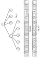
- Figure 9 illustrates for didactic purposes part of a hierarchical wireless mesh comprising, in relevant part, a parent node P at a first level of the hierarchy, intermediate nodes N1, N2, N3 & N4 as child nodes of parent node P, and child nodes C1, C2, C3, C4 & C5 of node N1.
- Each node, and its child node(s) avoid permanent scheduling locks by scheduling child nodes independently of the parent node.
- the number of child nodes scheduled in a given cycle interval is relatively prime to the number of child nodes associated with the parent node to ensure that there are no loops between a parent node and a given child node where the parent node services its parent every time it should service that child node.
- Two numbers are relatively prime if they have no common factors. Thus, four and three are relatively prime, though four is not prime. In one implementation, a node having a parent node advertising four children will schedule five children, even though it has only four, for instance.
- Relatively prime numbers have a property that ensures there are no inner cycles within the larger cycle, which is the multiple of the two prime numbers. This property ensures that scheduling is fair and that no one child will be continually ignored as its parent node loops through the cycle interval.
- Figures 10A and 10B illustrate how parent node P and its child node N1 schedule their respective data and contention slots according to one possible implementation of the present invention.
- a given node determines its schedule for that cycle, and schedules its children and parent slots or antennas accordingly. Contention slots can be used to service missed child slots, schedule off channel neighbor discovery, and/or enhance data transfer for children with excess data.
- a parent node schedules the slots in the cycle interval, and communicates to each child node the slot schedule and the effective number of its child nodes. Each child node, in turn, uses this slot scheduling information to compute its own slot schedule.
- parent node P has 4 child nodes, and no parent node (rather, it is directly connected to wireless mesh control system 20). Accordingly, it allocates the available data slots 1-11 evenly across its child nodes N1-N4. As Figure 10A illustrates, during the next cycle interval, parent node P continues cycling through its child nodes. As discussed in more detail below, parent node P communicates this slot schedule as well as the number of effective child nodes to child node N1 (as well as other child nodes). Child node N1 uses this information to create its own slot schedule.
- child node N1 schedules transmissions with its parent node P during slots 1, 5, 9 in the first cycle of data slots, by overlaying the slot schedule handed to it by its parent node over the data slot schedule that would result by cycling through all child nodes.
- each node re-computes its slot schedule when it receives slot announcement messages.
- each node computes an effective number of children for purposes of computing a slot schedule based on the number of children it actually has and the effective number of children advertised by its parent.
- scheduling fairness is ensured by maintaining a relatively prime relationship between the effective number of children between a parent node and a child node. In other words, this relatively prime relationship prevents a given child routing node of the present node from having its data slots repeatedly taken for communications with the parent node of the present node.
- each routing node consults the following table (or other data structure) to compute the advertised value of effective children based on the effective number of children advertised by its parent and its actual number of children.
- the left-hand column corresponds to the parent node's advertised effective number of children, the top row is the actual number of children a given node has, and each indexed cell is the number the node should advertise as its effective children.
- the effective number of children is greater than the actual number of children.
- the node nevertheless computes the data slot schedule according to the effective number of children to maintain the relatively prime relationship discussed above.
- data slots corresponding to a "phantom" child node are essentially dead slots as there is actually no child node with which to communicate.
- the routing node may perform other operations during phantom data slots, such as scanning its coverage area to potentially acquire additional child nodes, broadcasting neighbor request packets and the like.
- a routing node, by configuration is limited to acquiring no more than N child nodes, where N is a configurable parameter (e.g., 5, 7, etc.).
- a routing node determines its transmission schedule for that cycle interval, and schedules its children and parent slots accordingly.
- a routing node may also recomputed its transmission schedule upon receipt of new information in a slot announcement packet from a parent routing node.
- the following variables are determined at the beginning of each cycle: 1) the number of effective children, and 2) the slots that each child node uses. This information is transmitted to the child node in slot announcement packets or PDUs.
- clock synchronization across routing nodes is accomplished by a parent node transmitting a time stamp to its children in slot announcement packets, as discussed more fully below. The child receives the slot announee packet, and marks the time it received the packet. The over the air time is calculated as the time to transmit the packet and demodulate and receive the packet. The receive time and transmit time are compared, and the two clocks can then be synchronized, as adjusted by the time to transmit and receive the packet.
- the slot announcement packets include: 1) the time of the TSF timer that the packet was transmitted, 2) 16 bits of what the local TSF timer should read for the slot start time, 3) the time (in microseconds the child node is permitted to use for data transfer, 4) the current slot number in the circular slot number sequence space, 5) the effective number of child nodes and the start position of the child node relative to the epic slot number "0"; 6) the actual number of child nodes and the start position of the child node relative to the epic slot number "0”; and 7) the mini-slot number in which the slot announcement packet was transmitted.
- the slot announcement packet may include other information as well, such as the amount of data buffered for the child node; the number of children allocated to the slot (1 for data slots, and equal to or greater than 1 for contention slots); and the number of microseconds of transmission time allocated to the child node in the next slot.
- a routing node when a routing node transmits a slot announcement packet, it queues the slot announcement packet along with the lesser of 1) any data packets destined for the child node and 2) the number of packets the node may transmit without exceeding the amount of time in the data slot accounting for the amount of transmission time allotted to the child node in the previous slot announcement packet.
- the routing node uses the acknowledgment frame transmitted by the child node in response to the slot announcement packet to begin sending any queued data frames.
- Child routing nodes may transmit slot response frames to their respective routing nodes.
- child routing nodes transmit slot response frames to parent nodes periodically as keep-alive messages to the parent node, and whenever a child node has significant amounts of data to transmit to its parent routing node.
- Slot response frames can include the following information: 1) microseconds of queued data, and 2) the slot number.
- At the beginning of a slot in which a child node is meant to communicate with its parent it selects the antenna oriented towards its parent. If the node has data to transfer, it queues a slot response frame along with data that may be transmitted in the slot.
- the mini slots are used to allow contention between other interfering nodes in the same physical sector that are synchronized to the same slot and to ensure that no one routing node always gains access to the data slot.
- the node then awaits a slot announcement from its parent. Upon receipt of the announcement, the node copies the slot announcement information into its parent adjacency, and updates its slot start time. The routing node also marks its parent adjacency as having been serviced.
- FIG 11A illustrates a process flow, according to one implementation of the present invention, directed to the slot scheduling and data transmission process implemented by the routing nodes.
- a node clears all flags in its adjacency data structure (302), and computer the data slot schedule for the current cycle interval (304).
- the node then cycles through each data slot according to the computed schedule (see Figure 11B ) (306).
- each node then proceeds through a contention slot cycle (312).
- each node scans its adjacency data structure to determine whether any child nodes were not serviced during the data slot cycle and schedules the child nodes during the contention slot cycle (308).
- the routing node scans the adjacency data structure to determine whether it was serviced by its parent node during the data slot cycle and schedules data transfer with its parent during the appropriate contention slot cycle (310).
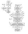
- each routing node determines whether it received a slot announcement message from its parent node (320). If so, the routing node resets a re-sync counter (322). If not, the routing node increments the re-sync counter (324). If the routing node does not receive a slot announcement message within a threshold (th1) number of cycles (326), the routing node enters a re-synchronization phase to re-acquire a parent node (328), see below.
- Figure 11B illustrates the process flow, according to one implementation of the present invention, during the data slot phase of a cycle interval.
- a given node can communicate with a parent node or a child node during any given data slot.
- a routing node selects an antenna associated with the routing node with which it will communicate during the next data slot (352).
- the remainder of the process flow for each data slot depends on whether the node communicates with a parent or a child node (354).
- a parent node transmits a slot announcement message or frame to mark the beginning of the data slot (356).
- the parent node transmits a slot announcement frame (see above) which is a directed or unicast packet to the child node scheduled in the data slot.
- a slot announcement frame is broadcast.
- the slot scheduling information in the slot announcement packet allows the child node to determine during which slots the child should attend to data transfer with the parent node.
- the child node upon receipt of a slot announcement frame (364), the child node transmits a slot acknowledgment to its parent (365). Upon receipt of the slot announcement frame, the child node copies the slot scheduling information in the slot announcement frame into its parent adjacency data structure, and updates its slot start time (366). In one implementation, the node marks its parent adjacency as having been serviced for that cycle interval.
- the slot announcement acknowledgement in one implementation, may include the amount of data the child has to transmit, and by extension a value of 0 indicates that flow control is in effect. In one implementation, the data flow control bit is set when a node has too much data in the aggregate to transmit to its parent and children, and therefore is running out of buffer space. Routing nodes do not transmit data to other nodes that have this bit set in the slot announcement or acknowledgment packets, which they transmit.
- a routing node can determine its next parent data slot, as well as the next data slots for its child routing nodes as follows. Let Sn be the schedule number of the routing node closest to slot zero in the circular slot sequence space. If schduling a parent, this is the slot number in the slot announce packet, otherwise it is the slot number assigned by the node to the child (e.g., slot 0 of effective number of children, slot 1 of effective number of children, etc.). Furthermore, let Cs be the current slot number.
- Cn the cycle number for either the parent routing node or a child routing node.
- Cn is the number of children the parent advertises in the slot announce frame.
- Cn is the number of effective children advertised to them.
- Ns is the next data slot in which to schedule the node (child or parent)
- Ns + Sn is the data slot in the next cycle
- Ns + 2Sn is the data slot for the next, and so on.
- contention slots are not used; this scheduling algorithm should be modified accordingly.
- Figures 12 and 13 illustrate the major components and anatomy of a data slot.
- Each data slot in one implementation, is large enough for a routing node, at the expiration of a previous data slot, to switch antennas to a parent or child node, transmit or receive a slot announcement frame, and transfer data.
- the mini-slots are used to manage interference across routing nodes in a given area or sector.
- mini-slot duration spans the time to transmit a slot announcement frame, plus propagation delay to transmit the frame to the maximum range at which the frame may be received, and the amount of time to process the frame and suspend transmission. In one implementation this time is set to 20 microseconds; however, other mini-slot durations can be configured.
- a routing node determines the mini-slots during which it begins transmission on a random basis.
- the routing node may employ a random number generator to select a mini slot.
- Mini-slots can be used to randomize access into the slot between nodes in the sector that are synchronized to the same slot and, in one implementation, are meant to ensure that no single node always gains access to the data slot.
- the use of mini-slots allows a given routing node to defer to another node that has an earlier mini-slot.
- the number of mini-slots is increased significantly to handle the greater number of potential interferers.
- the delay (in one implementation, a 20 microsecond delay) between parent and child mini-slots is used in some implementations to prevent accidental swapping of start times. Based on experimental results, there appears to be some observed jitter in the slot starting time. Therefore, a 20 microsecond delay makes the swap less likely. The cost of this happening is not great; however, it is undesirable. Mini-slots, however, may be used in connection with other algorithms and processes.
- the slot guard dead time at the end of the slot is to help prevent slot overruns.
- the antenna switch time allows for the radio to be prepared to receive and transmit in the new slot. This step is just dead time in an omni-directional antenna setup; and thus can be set to zero.
- Figure 13 illustrates data transfer within a data slot between a parent and child node, according to one implementation of the present invention.
- Parent and child nodes cover their entire data transfer time by issuing an RTS frame that includes the entire delay for transmitting all packets they are sourcing during the data slot.
- RTS frame that includes the entire delay for transmitting all packets they are sourcing during the data slot.
- data packets are transmitted only requiring an ACK.
- the ACK is used to determine whether or not the packet was successfully transmitted to the destination routing node. Packets that are not acknowledged are re-queued for later transmission.
- the parent routing node need not transmit a slot announcement packet, in each data slot, with the child nodes.
- the routing node protocol discussed is configured such that a parent routing node communicates with each child on the order of once or twice per second. This is usually sufficient to keep the clocks in synchronization.
- Routing nodes may transmit slot announcement packets on a periodic or semi-regular basis to ensure that clock drift does not become significant, and/or to ensure that a child node does not consider the parent node to have been de-activated or lost timing. Routing nodes may also transmit slot announcement packets in response to an indication that the child node has requested a volume of data transfer in an amount greater than a default data volume.
- a parent routing node wishing to communicate during a contention slot cycle awaits the beginning of the slot, and issues a broadcast availability announcement. Child nodes receiving this announcement acknowledge their parent, and transfer available data. Nodes that have no children they feared and no parents with whom they lacked communications, are free to either attempt additional data transfer during the contention phase with either children or parent, or to attempt neighbor discovery and acquisition on other channels.
- a routing node may use its child contention slots according to the following preferences.
- Parent contention slots are scheduled with the following priorities: If the slots have been dedicated to neighbor discovery, the parent slots are used for that purpose. Otherwise, the routing node selects the antenna oriented towards its parent, and listens for slot announcement packets. Upon receipt, if the parent has no data to transmit, and the child has no data to transmit, and the announcement is multicast, the announcement is ignored. Otherwise, the child transmits a directed slot announcement acknowledgement, and data transfer may commence.
- a given routing node may lose synchronization with its parent node for a variety of reasons. For example, the parent routing node may have gained or lost a child node, which causes the parent to re-compute its slot schedule. The new slot schedule may prevent the child node from receiving slot announcement messages from the parent. Other reasons for synchronization loss may be caused by a hardware failure on the parent routing node, or by the parent node being taken out of service. Furthermore, environmental changes, such as a new source of RF interference may cause a child routing node to lose synchronization with its parent node.
- a routing node detects a change (such as a node failure) in its parent routing node, if it does not receive a slot announcement message after eight cycle intervals. During this time, the routing node continues to execute the current slot schedule and communicates with its child nodes, transmitting any queued data and receiving data from the child nodes. At the end of the eight-slot cycle period (see Figure 11A , Ref. No. 326), however, the routing node selects an antenna oriented toward its parent node and re-enters the SYNC state.
- a change such as a node failure
- the routing node transmits neighbor request packets to the parent routing node (702), and waits for a response from the parent routing node, in one implementation, for four cycle intervals (704, 706).
- the routing node blacklists the parent (708) and chooses another tentative parent, if any ⁇ with which to attempt synchronization (710, 712).
- the child nodes of the routing node also detect a change since they cease to obtain slot announcement messages from the routing node. Like the instant routing node, however, the child nodes wait 8 (Th1) cycle intervals before re-entering the SYNC state.
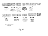
- Figure 16 illustrates the timing of the actions taken by a routing node as it detects a change in its parent routing node and ultimately enters the SYNC state. Specifically, Figure 16 shows a routing node that loses its parent, is unsuccessful in re-acquiring the parent, is unable to acquire a second parent, but ultimately is successful with a third routing node. The lower portion of Figure 16 illustrates the effect of these actions on the child node of the instant routing node.
- the parent failure timeout here, eight cycle intervals
- the acquire timeout here, four cycle intervals
- the effect of synchronization loss on the overall mesh network is reduced or mitigated. For example, if a routing node re-acquires its parent node, the lower portion of the hierarchical mesh will remain in its current state, unless a topology or data slot schedule change occurs. For instance, if it takes 12 cycles to time out a parent node, but only four to acquire a new parent, then a routing node that loses its parent node, but reacquires that parent node or another, will not lose its child node(s).
- mesh network control system 20 includes functionality supporting mesh network routing operations.
- uplink and downlink routing information is dynamically configured according to a route discovery process detailed below.
- routing algorithms described below are intended for didactic purposes to illustrate operation the present invention in one possible mesh network implementation. Accordingly, other routing algorithms and processes can also be used.
- Mesh network control system 20 in one implementation, is configured with all routes that define the hierarchical mesh network configuration.
- Mesh network control system 20 in one implementation, composes and transmits, for each hierarchical tree, route discovery packets, including routing information, to the leaf routing nodes 34 on each branch of a given tree.
- the routing nodes in the path to the leaf routing nodes 34 may also learn the identity of their respective parent and child routing nodes as the route discovery packet traverses the mesh network.
- a route discovery packet includes a Message Routing Header 204 including the route to a leaf routing node 34.
- routing node 1 Upon receipt of a route discovery packet, routing node 1 sends it to the next hop identified in the message routing header.
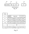
- FIG 14 illustrates some of the headers in a wireless frame transmitted between routing nodes.
- Figure 15 illustrates a Message Routing Header according to one implementation of the present invention.
- the wireless frame in one implementation, is an 802.11 frame including an 802.11 header 202 encapsulating a Mesh Routing Header (MRH) 204.
- MMRH Mesh Routing Header
- Other headers can include 802.3 or other link layer headers for use by the last hop routing node, as discussed more fully below, and IP headers 208.
- the routing nodes in the mesh network learn the MAC addresses of their parent and child routing nodes, as well as the route and hopcount along the path from the root routing node 30 to the leaf routing node 34.
- the information in the MRH of the route discovery packet allows the routing nodes to properly route wireless frames in the uplink direction.
- Use of route discovery packets in this manner obviates the need to manually configure uplink and downlink MAC addresses at each routing node.
- mesh network control system 20 can dynamically reconfigure the routes in the hierarchical mesh network simply by composing MRHs that define the desired routes and transmit them in route discovery packets to the leaf routing nodes 34. In one implementation, the leaf routing node 34 simply discards the route discovery packet.
- the leaf routing node 34 when the route discovery packet reaches a leaf routing node 34, the leaf routing node 34 records the MRH information, clears the MRH, and transmits the route discovery packet uplink to mesh network control system 20.
- the routing nodes at each hop add their MAC address to the MRH and route the packet to an upstream routing node using a least cost or other routing algorithm. In this manner, the mesh network control system 20 can learn new routes and possibly apply them by sending route discovery packets in the downstream direction.
- each packet sent or received at the mesh routing control system 20 to or from a routing node hierarchy is encapsulated with a Message Routing Header (MRH) that contains the path to the destination.
- MGW Message Routing Header
- Figure 15 illustrates a Message Routing Header according to an implementation of the present invention.
- the "D" in the control word indicates whether the route is read from the top or bottom.
- uplink routing from a wireless client to network 50 for example, is static and based on the Message Routing Header information recorded by the routing node during processing of route discovery packets.
- a routing node receiving a wireless frame performs one of the following operations: 1) stripping the 802.11 header and Message Routing Header and passing the packet to the WLAN interface, if the final MAC hop identified in the MRH is the processing routing node; and 2) updating the destination MAC address in the 802.11 header 202 with the next hop MAC address in the MRH, and placing the packet in an appropriate upstream or downstream queue for subsequent transmission.
- Mesh network control system 20 adds and strips off the Message Routing Header for all packets going to or coming from a hierarchical tree in the mesh network.
- Mesh network control system 20 is also operative to bridge wireless traffic from the mesh network onto network 50.
- the mesh network control system 20 includes a graphical user interface (GUI) to assist in mesh organization, statistics gathering and route monitoring.
- GUI graphical user interface
- mesh network control system 20 is operative to monitor to which routing node each wireless client is associated.
- each routing node can be configured to transmit a notification, such as an SNMP trap, to mesh network control system 20 after a wireless client associates with access point functionality of the routing node.
- mesh network control system 20 can detect new wireless client MAC addresses in the data flows that traverse the mesh network control system 20. Further, in one implementation, all wireless client traffic emanating from a wireless client 40 is first transmitted uplink to mesh network control system 20, which may apply policies to the traffic, before the wireless traffic is transmitted back downlink to another wireless client. Lastly, mesh network control system 20 may include interfaces and associated functionality that facilitate management and operation of the WLAN access point functionality at the routing nodes.
Landscapes
- Engineering & Computer Science (AREA)
- Computer Networks & Wireless Communication (AREA)
- Signal Processing (AREA)
- Databases & Information Systems (AREA)
- Mobile Radio Communication Systems (AREA)
Claims (14)
- Verfahren zur Minderung des Synchronisationsverlustes zwischen einem Eltern- und einem Kind-Knoten in einem hierarchischen Mesh-Netzwerk, umfassend:Warten, an einem im Wartungszustand befindlichen Kind-Knoten, auf eine Planungsnachricht von einem Eltern-Routingknoten zur Aufrechterhaltung der Synchronisation mit dem Eltern-Routingknoten;bei Nicht-Empfangen einer Planungsnachricht vom Eltern-Routingknoten innerhalb eines Ausfallzeitintervalls Eintreten des Kind-Knotens in einen Synchronisationszustand für ein Erfassungszeitintervall in dem Versuch, den Eltern-Routingknoten erneut zu erfassen;wobei der Kind-Knoten in den Wartungszustand eintritt, wenn der Eltern-Routingknoten neu erfasst wird; und wobei das Erfassungszeitintervall kleiner als das Ausfallzeitintervall ist;falls der Eltern-Routingknoten nicht neu erfasst wird, Auswahl eines Nachbar-Routingknotens durch den Kind-Knoten als provisorischer Eltern-Routingknoten; undEintreten des Kind-Knotens in den Synchronisationszustand mit dem provisorischen Eltern-Routingknoten für ein Erfassungszeitintervall.
- Verfahren nach Anspruch 1, wobei der Synchronisationszustand umfasst:Übertragen mindestens einer Anfrage an den Eltern-Routingknoten, undWarten auf eine Antwort vom Eltern-Routingknoten auf die Anfrage.
- Verfahren nach Anspruch 1, wobei das Erfassungszeitintervall kleiner als oder gleich der Hälfte des Ausfallzeitintervalls ist.
- Verfahren nach Anspruch 1, wobei der Wartungszustand ferner das Übertragen von Slot-Planungsnachrichten an mindestens einen Kind-Knoten umfasst.
- Verfahren nach Anspruch 1 oder Anspruch 4, wobei der Wartungszustand ferner umfasst:Berechnen eines Daten-Slotplans auf Basis der in den vom Eltern-Routingknoten empfangenen Planungsnachrichten enthaltenen Information; undÜbertragen von Daten an den, und Empfangen von Daten von, dem Eltern-Routingknoten gemäß des Daten-Slotplans.
- Verfahren nach Anspruch 5, wobei der Wartungszustand ferner das Übertragen von Daten an mindestens einen Kind-Knoten, bzw. das Empfangen von Daten von demselben gemäß des Daten-Slotplans umfasst.
- Verfahren nach Anspruch 1, ferner umfassend das Entdecken von Nachbar-Routingknoten.
- Drahtloser Routingknoten zum Einsatz als Kind-Knoten in einem hierarchischen drahtlosen Mesh-Netzwerk, umfassend:eine drahtlose Netzwerkschnittstelle zur Kommunikation mit einem Eltern-Routingknoten;einen oder mehrere Prozessoren;einen Speicher;eine im Speicher gespeicherte Routingknoten-Anwendung mit Anweisungen, die dazu dienen, den oder die Prozessoren und die drahtlose Netzwerkschnittstelle zu veranlassen,einen Wartungszustand, umfassend das Warten auf eine Planungsnachricht von einem Eltern-Routingknoten, auszuführen, um die Synchronisation mit dem Eltern-Rutingknoten aufrechtzuerhalten;bei Nicht-Empfangen einer Planungsnachricht vom Eltern-Routingknoten innerhalb eines Ausfallzeitintervalls für ein Erfassungszeitintervall in einen Synchronisationszustand einzutreten, in dem Versuch den Eltern-Routingknoten neu zu erfassen;in den Wartungszustand einzutreten, wenn der Eltern-Routingknoten neu erfasst wird; wobei das Erfassungszeitintervall kleiner als das Ausfallzeitintervall ist;falls der Eltern-Routingknoten nicht neu erfasst wird, einen Nachbar-Routingknoten als provisorischen Eltern-Routingknoten auszuwählen; undfür ein Erfassungszeitintervall in den mit dem provisorischen Eltern-Routingknoten in den Synchronisationszustand einzutreten.
- Drahtloser Routingknoten nach Anspruch 8, wobei die Routingknoten-Anwendung ferner Anweisungen umfasst, die dazu dienen, den oder die Prozessoren und die drahtlose Netzwerkschnittstelle zu veranlassen, im Synchronisationszustand
mindestens eine Anfrage an den Eltern-Routingknoten zu übertragen;
auf eine Antwort vom Eltern-Routingknoten auf die Anfrage zu warten. - Drahtloser Routingknoten nach Anspruch 8, wobei das Erfassungszeitintervall kleiner als oder gleich der Hälfte des Ausfallzeitintervalls ist.
- Drahtloser Routingknoten nach Anspruch 8, wobei die Routingknoten-Anwendung ferner Anweisungen umfasst, die dazu dienen, den oder die Prozessoren und die drahtlose Netzwerkschnittstelle zu veranlassen, im Wartungszustand
Planungsnachrichten an mindestens einen Kind-Knoten zu übertragen. - Drahtloser Routingknoten nach Anspruch 8 oder Anspruch 11, wobei die Routingknoten-Anwendung ferner Anweisungen umfasst, die dazu dienen, den oder die Prozessoren und die drahtlose Netzwerkschnittstelle zu veranlassen, im Wartungszustand
einen Daten-Slotplan aufgrund der in den vom Eltern-Routingknoten empfangenen Planungsnachrichten enthaltenen Information zu berechnen; und
Daten gemäß des Daten-Slotplans an den Eltern-Routingknoten zu übertragen, bzw. von diesem zu empfangen. - Drahtloser Routingknoten nach Anspruch 12, wobei die Routingknoten-Anwendung ferner Anweisungen umfasst, die dazu dienen, den oder die Prozessoren und die drahtlose Netzwerkschnittstelle zu veranlassen, im Wartungszustand
Daten gemäß des Daten-Slotplans an mindestens einen Kind-Knoten zu übertragen, bzw. von diesem zu empfangen. - Drahtloser Routingknoten nach Anspruch 8, wobei die Routingknoten-Anwendung ferner Anweisungen umfasst, die dazu dienen, den oder die Prozessoren und die drahtlose Netzwerkschnittstelle zu veranlassen, Nachbar-Routingknoten zu entdecken.
Applications Claiming Priority (3)
| Application Number | Priority Date | Filing Date | Title |
|---|---|---|---|
| US66440605P | 2005-03-23 | 2005-03-23 | |
| US11/212,997 US7505450B2 (en) | 2005-03-23 | 2005-08-26 | Configuration of failure and acquire timeouts to facilitate recovery from failures in hierarchical mesh networks |
| PCT/US2006/010677 WO2006102558A2 (en) | 2005-03-23 | 2006-03-22 | Configuration of failure and acquire timeouts to facilitate recovery from failures in hierarchical mesh networks |
Publications (3)
| Publication Number | Publication Date |
|---|---|
| EP1862020A2 EP1862020A2 (de) | 2007-12-05 |
| EP1862020A4 EP1862020A4 (de) | 2010-10-27 |
| EP1862020B1 true EP1862020B1 (de) | 2013-07-31 |
Family
ID=37024660
Family Applications (1)
| Application Number | Title | Priority Date | Filing Date |
|---|---|---|---|
| EP06739466.8A Expired - Lifetime EP1862020B1 (de) | 2005-03-23 | 2006-03-22 | Konfiguration von fehler- und erfassungstimeouts zur wiederherstellung nach fehlern in hierarchischen mesh-netzwerken |
Country Status (4)
| Country | Link |
|---|---|
| US (1) | US7505450B2 (de) |
| EP (1) | EP1862020B1 (de) |
| CN (1) | CN101116352B (de) |
| WO (1) | WO2006102558A2 (de) |
Cited By (1)
| Publication number | Priority date | Publication date | Assignee | Title |
|---|---|---|---|---|
| US10055253B2 (en) | 2014-03-25 | 2018-08-21 | Mellanox Technologies, Ltd. | Reducing processor loading during housekeeping operations |
Families Citing this family (101)
| Publication number | Priority date | Publication date | Assignee | Title |
|---|---|---|---|---|
| US7346135B1 (en) | 2002-02-13 | 2008-03-18 | Marvell International, Ltd. | Compensation for residual frequency offset, phase noise and sampling phase offset in wireless networks |
| JP4390649B2 (ja) * | 2004-07-14 | 2009-12-24 | 富士通株式会社 | ネットワークループ検知装置 |
| US20060285480A1 (en) * | 2005-06-21 | 2006-12-21 | Janofsky Eric B | Wireless local area network communications module and integrated chip package |
| US7580382B1 (en) * | 2005-09-27 | 2009-08-25 | Rockwell Collins, Inc. | System and method for distributed channelized group formation in a mobile wireless communication network |
| US7706320B2 (en) * | 2005-10-28 | 2010-04-27 | Hunt Technologies, Llc | Mesh based/tower based network |
| US8204039B2 (en) * | 2005-11-30 | 2012-06-19 | Symbol Technologies, Inc. | System and method for data communication in a wireless network |
| KR100819042B1 (ko) * | 2005-12-08 | 2008-04-02 | 한국전자통신연구원 | 멀티캐스트 에이전트의 무선 랜 환경을 고려한 1:n오버레이 멀티캐스트 망 구성 방법 및 그 멀티캐스트에이전트 |
| US9686123B2 (en) * | 2015-10-19 | 2017-06-20 | Blackfire Research Corporation | System for media distribution and rendering on spatially extended wireless networks |
| US20070214254A1 (en) * | 2006-03-07 | 2007-09-13 | Anatoly Aguinik | Method and system for topology discovery in an ad hoc network |
| KR101245856B1 (ko) * | 2006-09-29 | 2013-03-20 | 삼성전자주식회사 | 이종 이상의 무선 통신 규격을 지원하는 멀티 무선 메쉬네트워크 시스템 및 그 제어방법 |
| US8102799B2 (en) * | 2006-10-16 | 2012-01-24 | Assa Abloy Hospitality, Inc. | Centralized wireless network for multi-room large properties |
| US8005002B2 (en) * | 2006-11-09 | 2011-08-23 | Palo Alto Research Center Incorporated | Method and apparatus for performing a query-based convergecast scheduling in a wireless sensor network |
| US8125930B2 (en) * | 2006-12-13 | 2012-02-28 | Rockstar Bidco Lp | Protocol for clock distribution and loop resolution |
| US10142013B2 (en) * | 2006-12-20 | 2018-11-27 | The Boeing Company | Method of optimizing an interplanetary communications network |
| US8149818B2 (en) * | 2006-12-30 | 2012-04-03 | Broadcom Corporation | Mesh network within a device |
| US7624309B2 (en) * | 2007-01-16 | 2009-11-24 | Microsoft Corporation | Automated client recovery and service ticketing |
| US8045505B2 (en) * | 2007-01-18 | 2011-10-25 | Science Applications International Corporation | Mechanism for automatic network formation and medium access coordination |
| US8717964B2 (en) * | 2007-03-09 | 2014-05-06 | Motorola Solutions, Inc. | Wireless wide-area communication network multihop relay station management |
| US8248948B2 (en) * | 2007-04-03 | 2012-08-21 | Tropos Networks, Inc. | Monitoring network conditions of a wireless network |
| US8645976B2 (en) * | 2007-05-03 | 2014-02-04 | Qualcomm Incorporated | Application programming interface (API) for restoring a default scan list in a wireless communications receiver |
| WO2009007630A1 (fr) * | 2007-07-03 | 2009-01-15 | France Telecom | Procede de gestion dynamique des ressources radio d'un reseau maille |
| WO2009015202A1 (en) * | 2007-07-23 | 2009-01-29 | Telcordia Technologies, Inc. | Systems and methods for multi-beam optic-wireless vehicle communications |
| US8130663B2 (en) * | 2007-09-14 | 2012-03-06 | At&T Intellectual Property I, L.P. | Methods and apparatus to route emergency communication sessions |
| US8654782B2 (en) * | 2007-11-05 | 2014-02-18 | Cisco Technology, Inc. | Mesh tree formation in wireless networks |
| US7995467B2 (en) * | 2007-12-12 | 2011-08-09 | Synapsense Corporation | Apparatus and method for adapting to failures in gateway devices in mesh networks |
| US8351369B2 (en) * | 2007-12-12 | 2013-01-08 | Synapsense Corporation | Apparatus and method for adaptive data packet scheduling in mesh networks |
| US8885548B2 (en) | 2007-12-28 | 2014-11-11 | Synapsense Corporation | Apparatus and method for admitting new devices in a self-healing, self-organizing mesh network |
| US8331282B2 (en) * | 2007-12-28 | 2012-12-11 | Synapsense Corporation | Apparatus and method for adaptive channel hopping in mesh networks |
| US8040791B2 (en) * | 2008-02-13 | 2011-10-18 | Cisco Technology, Inc. | Coordinated channel change in mesh networks |
| US7793002B2 (en) * | 2008-06-06 | 2010-09-07 | Fisher-Rosemount Systems, Inc. | Methods and apparatus for implementing a sequential synchronization hierarchy among networked devices |
| US8473898B2 (en) | 2008-07-08 | 2013-06-25 | Synapsense Corporation | Apparatus and method for building integrated distributed applications for use with a mesh network |
| US8059563B2 (en) * | 2008-07-31 | 2011-11-15 | Aruba Networks, Inc. | Assigning slots in a mesh network |
| US8532003B2 (en) | 2008-10-03 | 2013-09-10 | Synapsense Corporation | Apparatus and method for managing packet routing through internally-powered network devices in wireless sensor networks |
| US8644186B1 (en) * | 2008-10-03 | 2014-02-04 | Cisco Technology, Inc. | System and method for detecting loops for routing in a network environment |
| US8600560B2 (en) | 2008-12-30 | 2013-12-03 | Synapsense Corporation | Apparatus and method for controlling computer room air conditioning units (CRACs) in data centers |
| US8538584B2 (en) | 2008-12-30 | 2013-09-17 | Synapsense Corporation | Apparatus and method for controlling environmental conditions in a data center using wireless mesh networks |
| US8194592B2 (en) * | 2009-01-15 | 2012-06-05 | Honeywell International Inc. | Wireless monitoring and alarm system |
| US8160838B2 (en) * | 2009-04-30 | 2012-04-17 | Synapsense Corporation | Apparatus and method for visualizing environmental conditions in a data center using wireless sensor networks |
| JP5445593B2 (ja) * | 2009-10-15 | 2014-03-19 | 富士通株式会社 | 無線通信装置および無線通信プログラム |
| US8468160B2 (en) * | 2009-10-30 | 2013-06-18 | International Business Machines Corporation | Semantic-aware record matching |
| US20110106836A1 (en) * | 2009-10-30 | 2011-05-05 | International Business Machines Corporation | Semantic Link Discovery |
| US20110181412A1 (en) * | 2010-01-22 | 2011-07-28 | Assa Abloy Hospitality, Inc. | Energy management and security in multi-unit facilities |
| US20110194630A1 (en) * | 2010-02-10 | 2011-08-11 | Yang Hua-Lung | Systems and methods for reporting radio link failure |
| JP5429024B2 (ja) * | 2010-04-28 | 2014-02-26 | ブラザー工業株式会社 | 情報通信システム、ノード装置、情報通信方法及びプログラム |
| US8811377B1 (en) | 2010-08-30 | 2014-08-19 | Synapsense Corporation | Apparatus and method for instrumenting devices to measure power usage using a multi-tier wireless network |
| CN102014481B (zh) * | 2010-12-13 | 2015-06-03 | 中兴通讯股份有限公司 | 一种对网络链路时钟进行维护的方法及系统 |
| US8595359B2 (en) | 2011-03-08 | 2013-11-26 | Cisco Technology, Inc. | Efficient message distribution for directed acyclic graphs |
| US9210045B2 (en) | 2011-03-08 | 2015-12-08 | Cisco Technology, Inc. | Gravitational parent selection in directed acyclic graphs |
| US9723538B2 (en) * | 2011-06-20 | 2017-08-01 | Cisco Technology, Inc. | Systematic neighbor detection in shared media computer networks |
| US8619789B2 (en) | 2011-07-12 | 2013-12-31 | Cisco Technology, Inc. | Timing re-synchronization with reduced communication energy in frequency hopping communication networks |
| US9338757B2 (en) * | 2011-10-03 | 2016-05-10 | Texas Instruments Incorporated | Clock synchronization and centralized guard time provisioning |
| JP5770602B2 (ja) * | 2011-10-31 | 2015-08-26 | トヨタ自動車株式会社 | 通信システムにおけるメッセージ認証方法および通信システム |
| DE102012101849B4 (de) * | 2012-03-06 | 2021-05-27 | Techem Energy Services Gmbh | Verfahren zur Organisation und/oder Inbetriebnahme eines Netzwerkes zur Kommunikation und Netzwerkknoten |
| WO2014016695A2 (en) | 2012-07-27 | 2014-01-30 | Assa Abloy Ab | Presence-based credential updating |
| ES2872351T3 (es) | 2012-07-27 | 2021-11-02 | Assa Abloy Ab | Controles de ajuste automático basados en la información de presencia fuera de la habitación |
| US20140071885A1 (en) * | 2012-09-10 | 2014-03-13 | Qualcomm Incorporated | Systems, apparatus, and methods for bridge learning in multi-hop networks |
| US9037896B2 (en) | 2012-11-05 | 2015-05-19 | Cisco Technology, Inc. | Root cause analysis in a sensor-actuator fabric of a connected environment |
| US20140160979A1 (en) * | 2012-12-12 | 2014-06-12 | Futurewei Technologies, Inc. | Determination and Visualization of Hierarchical Network Topology |
| US9225589B2 (en) * | 2013-06-19 | 2015-12-29 | Cisco Technology, Inc. | Fast reroute using different frequency-hopping schedules |
| US9225595B2 (en) * | 2013-06-28 | 2015-12-29 | Arista Networks, Inc. | Method and system for zero touch replacement of network infrastructure |
| US9356875B2 (en) * | 2013-07-22 | 2016-05-31 | Cisco Technology, Inc. | Using statistical and historical information of topology metrics in constrained networks |
| US9565575B2 (en) * | 2013-07-25 | 2017-02-07 | Honeywell International Inc. | Interference avoidance technique for wireless networks used in critical applications |
| US9749254B2 (en) * | 2014-05-19 | 2017-08-29 | Cisco Technology, Inc. | Hierarchical scheduler for deterministic networking |
| AU2014403118B2 (en) * | 2014-08-07 | 2018-11-08 | Telefonaktiebolaget Lm Ericsson (Publ) | Methods implemented in access nodes for maintaining synchronization in radio access network and associated access nodes |
| CN105592477A (zh) * | 2014-10-31 | 2016-05-18 | 中兴通讯股份有限公司 | 邻区检测方法、装置及通信设备 |
| JP6079768B2 (ja) * | 2014-12-15 | 2017-02-15 | トヨタ自動車株式会社 | 車載通信システム |
| US10243832B2 (en) | 2014-12-23 | 2019-03-26 | Industrial Technology Research Institute | Routing message delivery method applicable to network node and network node using the same and communication network using the same |
| JP2016201775A (ja) * | 2015-04-14 | 2016-12-01 | 富士通株式会社 | 無線通信システム、無線通信装置、及び無線通信方法 |
| US10051587B2 (en) * | 2015-07-09 | 2018-08-14 | Google Llc | System for network discovery and synchronization |
| PL3326331T3 (pl) * | 2015-07-17 | 2021-10-11 | Vitir As | Centralny system sterowania interakcjami i współpracą urządzeń radiowych pracujących w sieci kratowej z obsługą wielu protokołów komunikacyjnych |
| JP6646248B2 (ja) | 2015-08-19 | 2020-02-14 | ヤマハ株式会社 | オーディオシステム、オーディオ機器およびオーディオシステムの再接続方法 |
| JP2018528686A (ja) * | 2015-08-21 | 2018-09-27 | リニアー テクノロジー エルエルシー | 複数アクセスポイント無線メッシュネットワーク |
| EP3142322B1 (de) * | 2015-09-10 | 2018-04-25 | Alcatel Lucent | Selbstkonfigurationsserver und verfahren |
| US10193742B2 (en) * | 2015-10-29 | 2019-01-29 | Kodacloud Inc. | Selecting a corrective action for a network connection problem based on historical data |
| US10256895B2 (en) * | 2015-11-02 | 2019-04-09 | Cable Television Laboratories, Inc. | System and method for fast relay for bandwidth allocation signaling |
| EP3375113A4 (de) * | 2015-11-09 | 2019-07-17 | Wiser Systems, Inc. | Verfahren zur synchronisation mehrerer vorrichtungen und ortsbestimmung basierend auf den synchronisierten vorrichtungen |
| US10123347B2 (en) | 2015-12-04 | 2018-11-06 | Qualcomm Incorporated | Method and apparatus for decoupling uplink latency using common uplink burst in TDD subframe structure |
| US9713180B1 (en) | 2016-03-15 | 2017-07-18 | Qualcomm Incorporated | Relay centric mobility management in a mesh network |
| US9717110B1 (en) | 2016-03-15 | 2017-07-25 | Qualcomm Incorporated | User equipment centric mobility management in a mesh network |
| CN109076431B (zh) * | 2016-04-19 | 2022-03-11 | 三菱电机株式会社 | 无线通信装置和无线通信方法 |
| US11076370B2 (en) * | 2016-06-07 | 2021-07-27 | Texas Instruments Incorporated | Node synchronization for networks |
| GB2551328B (en) | 2016-06-10 | 2020-02-19 | Bluwireless Tech Ltd | Clock synchronisation in wireless mesh communications networks |
| GB2551327B (en) * | 2016-06-10 | 2020-02-19 | Bluwireless Tech Ltd | Clock synchronisation in wireless mesh communications networks |
| JP6709982B2 (ja) * | 2016-07-19 | 2020-06-17 | パナソニックIpマネジメント株式会社 | 通信システム、通信装置 |
| US10084536B1 (en) | 2016-08-25 | 2018-09-25 | Star Mesh LLC | Radio system using satellites |
| EP3352527A1 (de) | 2017-01-24 | 2018-07-25 | ABB Schweiz AG | Drahtloskommunikationsnetzwerk |
| US10594614B2 (en) * | 2017-05-19 | 2020-03-17 | Bsquare Corp. | Context aware routing |
| CN108055679B (zh) * | 2018-01-26 | 2020-11-13 | 乐鑫信息科技(上海)股份有限公司 | 一种mesh网络流控的方法 |
| CN110392395B (zh) | 2018-04-23 | 2022-03-29 | 华为技术有限公司 | 发送报文的方法和发送报文的装置 |
| US11095728B2 (en) * | 2018-06-21 | 2021-08-17 | Disney Enterprises, Inc. | Techniques for automatically interpreting metric values to evaluate the health of a computer-based service |
| US10911929B2 (en) * | 2018-07-13 | 2021-02-02 | Itron, Inc. | Power-efficient discovery process for nodes within a wireless mesh network |
| US11178530B2 (en) | 2018-07-13 | 2021-11-16 | Itron, Inc. | Power-efficient discovery process for nodes within a wireless mesh network |
| US11082324B2 (en) | 2018-07-27 | 2021-08-03 | goTenna Inc. | Vine: zero-control routing using data packet inspection for wireless mesh networks |
| US10911329B2 (en) * | 2019-05-13 | 2021-02-02 | Cisco Technology, Inc. | Path and cadence optimization for efficient data collection from devices |
| US11064418B2 (en) | 2019-09-09 | 2021-07-13 | Analog Devices International Unlimited Company | Two-hop wireless network communication |
| EP4059312A1 (de) * | 2019-11-11 | 2022-09-21 | Juganu Ltd. | Systeme und verfahren zum betreiben von baumbasierten drahtlosen netzwerken |
| CN110830995B (zh) * | 2019-11-14 | 2022-04-05 | 桂林电子科技大学 | 能使无线传感器网络源位置安全的多分支路由设计方法 |
| WO2021137218A2 (en) * | 2020-01-02 | 2021-07-08 | Lavi Gabriel | Methods and systems for supporting communication a plurality of client communication devices in a wireless local area network |
| US12402061B2 (en) * | 2020-01-10 | 2025-08-26 | Sony Group Corporation | Methods, infrastructure equipment and wireless communications networks |
| US11729092B2 (en) | 2020-07-02 | 2023-08-15 | Northrop Grumman Systems Corporation | System and method for multi-path mesh network communications |
| US11868219B2 (en) | 2022-05-04 | 2024-01-09 | Red Hat, Inc. | Data preservation for node evacuation in unstable nodes within a mesh |
Family Cites Families (19)
| Publication number | Priority date | Publication date | Assignee | Title |
|---|---|---|---|---|
| FI95978C (fi) * | 1994-03-01 | 1996-04-10 | Nokia Telecommunications Oy | Hierarkkinen synkronointimenetelmä |
| US6292508B1 (en) | 1994-03-03 | 2001-09-18 | Proxim, Inc. | Method and apparatus for managing power in a frequency hopping medium access control protocol |
| DE4446511A1 (de) * | 1994-12-24 | 1996-06-27 | Sel Alcatel Ag | Synchrones digitales Nachrichtenübertragungssystem mit hierarchischem Synchronisierungsnetz |
| FI103307B1 (fi) * | 1997-02-11 | 1999-05-31 | Nokia Telecommunications Oy | Tietoliikenneverkon synkronointi |
| US6714563B1 (en) * | 1999-04-26 | 2004-03-30 | Cisco Technology, Inc. | Network clock synchronization scheme |
| US6788702B1 (en) | 1999-10-15 | 2004-09-07 | Nokia Wireless Routers, Inc. | Protocol for neighborhood-established transmission scheduling |
| US6816510B1 (en) * | 2000-02-09 | 2004-11-09 | Koninklijke Philips Electronics N.V. | Method for clock synchronization between nodes in a packet network |
| US7031266B1 (en) | 2000-02-25 | 2006-04-18 | Cisco Technology, Inc. | Method and system for configuring wireless routers and networks |
| US7327683B2 (en) | 2000-03-16 | 2008-02-05 | Sri International | Method and apparatus for disseminating topology information and for discovering new neighboring nodes |
| EP1198085B1 (de) * | 2000-10-10 | 2011-06-08 | Sony Deutschland GmbH | Zyklussynchronisierung zwischen miteinander verbundenen Teilnetzwerken |
| US6965575B2 (en) | 2000-12-29 | 2005-11-15 | Tropos Networks | Selection of routing paths based upon path quality of a wireless mesh network |
| JP3698074B2 (ja) * | 2001-06-15 | 2005-09-21 | 日本電気株式会社 | ネットワーク同期方法、lsi、バスブリッジ、ネットワーク機器、およびプログラム |
| US7580394B2 (en) * | 2002-11-27 | 2009-08-25 | Nokia Corporation | System and method for collision-free transmission scheduling in a network |
| US7174170B2 (en) | 2003-02-12 | 2007-02-06 | Nortel Networks Limited | Self-selection of radio frequency channels to reduce co-channel and adjacent channel interference in a wireless distributed network |
| EP1629677B1 (de) | 2003-06-05 | 2014-12-31 | Meshnetworks, Inc. | Optimales routen in einem ad-hac-drahtloskommunikationsnetz |
| US7701858B2 (en) | 2003-07-17 | 2010-04-20 | Sensicast Systems | Method and apparatus for wireless communication in a mesh network |
| US7269155B2 (en) | 2004-01-13 | 2007-09-11 | Meshnetworks, Inc. | System and method for achieving continuous connectivity to an access point or gateway in a wireless network following an on-demand routing protocol, and to perform smooth handoff of mobile terminals between fixed terminals in the network |
| JP2008519533A (ja) | 2004-11-05 | 2008-06-05 | メッシュネットワークス インコーポレイテッド | 多重ホッピング・ネットワークにおける、ノード間の経路選択用の輻輳があるルーティング・メトリックを提供するためのシステム及び方法 |
| US7664055B2 (en) | 2005-03-21 | 2010-02-16 | Rf Monolithics, Inc. | System and method for synchronizing components in a mesh network |
-
2005
- 2005-08-26 US US11/212,997 patent/US7505450B2/en not_active Expired - Fee Related
-
2006
- 2006-03-22 EP EP06739466.8A patent/EP1862020B1/de not_active Expired - Lifetime
- 2006-03-22 CN CN200680003940XA patent/CN101116352B/zh not_active Expired - Fee Related
- 2006-03-22 WO PCT/US2006/010677 patent/WO2006102558A2/en not_active Ceased
Cited By (1)
| Publication number | Priority date | Publication date | Assignee | Title |
|---|---|---|---|---|
| US10055253B2 (en) | 2014-03-25 | 2018-08-21 | Mellanox Technologies, Ltd. | Reducing processor loading during housekeeping operations |
Also Published As
| Publication number | Publication date |
|---|---|
| CN101116352B (zh) | 2011-02-16 |
| EP1862020A4 (de) | 2010-10-27 |
| WO2006102558A3 (en) | 2007-04-19 |
| US7505450B2 (en) | 2009-03-17 |
| CN101116352A (zh) | 2008-01-30 |
| US20060215581A1 (en) | 2006-09-28 |
| WO2006102558A2 (en) | 2006-09-28 |
| EP1862020A2 (de) | 2007-12-05 |
Similar Documents
| Publication | Publication Date | Title |
|---|---|---|
| EP1862020B1 (de) | Konfiguration von fehler- und erfassungstimeouts zur wiederherstellung nach fehlern in hierarchischen mesh-netzwerken | |
| US9338727B2 (en) | Slot-based transmission synchronization mechanism in wireless mesh networks | |
| US7899027B2 (en) | Automatic route configuration in hierarchical wireless mesh networks | |
| EP1994689B1 (de) | Dynamische modifikation inhaltsbasierter übertragungssteuerungsparameter zur gewinnung eines lastenausgleichsschemas in drahtlosen mesh-netzwerken | |
| US11197242B2 (en) | Coordinated target wake time (TWT) service for localized wireless neighborhoods | |
| US7936681B2 (en) | Cross-layer design techniques for interference-aware routing configuration in wireless mesh networks | |
| CN103703844B (zh) | 用于覆盖独立单播调度的动态公共广播调度参数 | |
| US9001676B2 (en) | Collecting power outage notifications in a frequency hopping communication network | |
| CN100583670C (zh) | 无线通信系统、无线通信装置、无线通信方法和计算机程序 | |
| EP2280517B1 (de) | Verfahren und Vorrichtung zur Steuerung von Datenpaketübertragungen in drahtlosen Netzwerken zur Verbesserung des Netzaufbaus | |
| EP2008385B1 (de) | Verbesserung des spanning-tree-protokolls für blockierte, redundante verbindungen | |
| US8213409B2 (en) | System and method for communicating over mesh networks using waveform-enhanced, link-state routing | |
| US20050238058A1 (en) | Synchronization of upstream and downstream data transfer in wireless mesh topologies | |
| Tang et al. | Collision-avoidance transmission scheduling for ad-hoc networks | |
| Han et al. | Asynchronous multi-channel mac for vehicular ad hoc networks | |
| Sharma | Analysis of 802.11 b MAC: A QoS, fairness, and performance perspective | |
| CN111277304B (zh) | 一种基于多中继协作的单播传输方法及系统 | |
| Sankaranarayanan et al. | Enhancing wireless spectrum utilization with a cellular-ad hoc overlay architecture | |
| Chai et al. | M-Polar: channel allocation for throughput maximization in SDR mesh networks | |
| Bhardwaj | Lessons from a multichannel wireless mesh network | |
| Júlio et al. | Stub Wireless Multi-hop Networks using self-configurable Wi-Fi Basic Service Set Cascading | |
| Jackson | Hierarchical channel-access and routing protocols for heterogeneous multichannel ad hoc networks | |
| Pedro Júlio et al. | Stub Wireless Multi-hop Networks using Self-configurable Wi-Fi Basic Service Set Cascading | |
| Raniwala et al. | IEEE 802.11-BASED WIRELESS MESH NETWORKS | |
| Saluja | DISTRIBUTED SOURCE RATE LIMITING MECHANISM FOR WIRELESS MESH NETWORK |
Legal Events
| Date | Code | Title | Description |
|---|---|---|---|
| PUAI | Public reference made under article 153(3) epc to a published international application that has entered the european phase |
Free format text: ORIGINAL CODE: 0009012 |
|
| 17P | Request for examination filed |
Effective date: 20070723 |
|
| AK | Designated contracting states |
Kind code of ref document: A2 Designated state(s): AT BE BG CH CY CZ DE DK EE ES FI FR GB GR HU IE IS IT LI LT LU LV MC NL PL PT RO SE SI SK TR |
|
| DAX | Request for extension of the european patent (deleted) | ||
| A4 | Supplementary search report drawn up and despatched |
Effective date: 20100929 |
|
| 17Q | First examination report despatched |
Effective date: 20110517 |
|
| REG | Reference to a national code |
Ref country code: DE Ref legal event code: R079 Ref document number: 602006037628 Country of ref document: DE Free format text: PREVIOUS MAIN CLASS: H04Q0007240000 Ipc: H04W0040240000 |
|
| GRAP | Despatch of communication of intention to grant a patent |
Free format text: ORIGINAL CODE: EPIDOSNIGR1 |
|
| RIC1 | Information provided on ipc code assigned before grant |
Ipc: H04L 12/801 20130101ALI20130208BHEP Ipc: H04L 12/751 20130101ALI20130208BHEP Ipc: H04L 12/26 20060101ALI20130208BHEP Ipc: H04L 12/715 20130101ALI20130208BHEP Ipc: H04W 40/24 20090101AFI20130208BHEP Ipc: H04W 56/00 20090101ALI20130208BHEP |
|
| GRAS | Grant fee paid |
Free format text: ORIGINAL CODE: EPIDOSNIGR3 |
|
| GRAA | (expected) grant |
Free format text: ORIGINAL CODE: 0009210 |
|
| AK | Designated contracting states |
Kind code of ref document: B1 Designated state(s): AT BE BG CH CY CZ DE DK EE ES FI FR GB GR HU IE IS IT LI LT LU LV MC NL PL PT RO SE SI SK TR |
|
| REG | Reference to a national code |
Ref country code: GB Ref legal event code: FG4D Ref country code: CH Ref legal event code: EP |
|
| REG | Reference to a national code |
Ref country code: AT Ref legal event code: REF Ref document number: 625254 Country of ref document: AT Kind code of ref document: T Effective date: 20130815 |
|
| REG | Reference to a national code |
Ref country code: IE Ref legal event code: FG4D |
|
| REG | Reference to a national code |
Ref country code: DE Ref legal event code: R096 Ref document number: 602006037628 Country of ref document: DE Effective date: 20130926 |
|
| REG | Reference to a national code |
Ref country code: AT Ref legal event code: MK05 Ref document number: 625254 Country of ref document: AT Kind code of ref document: T Effective date: 20130731 |
|
| REG | Reference to a national code |
Ref country code: NL Ref legal event code: VDEP Effective date: 20130731 |
|
| REG | Reference to a national code |
Ref country code: LT Ref legal event code: MG4D |
|
| PG25 | Lapsed in a contracting state [announced via postgrant information from national office to epo] |
Ref country code: SE Free format text: LAPSE BECAUSE OF FAILURE TO SUBMIT A TRANSLATION OF THE DESCRIPTION OR TO PAY THE FEE WITHIN THE PRESCRIBED TIME-LIMIT Effective date: 20130731 Ref country code: LT Free format text: LAPSE BECAUSE OF FAILURE TO SUBMIT A TRANSLATION OF THE DESCRIPTION OR TO PAY THE FEE WITHIN THE PRESCRIBED TIME-LIMIT Effective date: 20130731 Ref country code: IS Free format text: LAPSE BECAUSE OF FAILURE TO SUBMIT A TRANSLATION OF THE DESCRIPTION OR TO PAY THE FEE WITHIN THE PRESCRIBED TIME-LIMIT Effective date: 20131130 Ref country code: CY Free format text: LAPSE BECAUSE OF FAILURE TO SUBMIT A TRANSLATION OF THE DESCRIPTION OR TO PAY THE FEE WITHIN THE PRESCRIBED TIME-LIMIT Effective date: 20130703 Ref country code: BE Free format text: LAPSE BECAUSE OF FAILURE TO SUBMIT A TRANSLATION OF THE DESCRIPTION OR TO PAY THE FEE WITHIN THE PRESCRIBED TIME-LIMIT Effective date: 20130731 Ref country code: PT Free format text: LAPSE BECAUSE OF FAILURE TO SUBMIT A TRANSLATION OF THE DESCRIPTION OR TO PAY THE FEE WITHIN THE PRESCRIBED TIME-LIMIT Effective date: 20131202 Ref country code: AT Free format text: LAPSE BECAUSE OF FAILURE TO SUBMIT A TRANSLATION OF THE DESCRIPTION OR TO PAY THE FEE WITHIN THE PRESCRIBED TIME-LIMIT Effective date: 20130731 |
|
| PG25 | Lapsed in a contracting state [announced via postgrant information from national office to epo] |
Ref country code: SI Free format text: LAPSE BECAUSE OF FAILURE TO SUBMIT A TRANSLATION OF THE DESCRIPTION OR TO PAY THE FEE WITHIN THE PRESCRIBED TIME-LIMIT Effective date: 20130731 Ref country code: PL Free format text: LAPSE BECAUSE OF FAILURE TO SUBMIT A TRANSLATION OF THE DESCRIPTION OR TO PAY THE FEE WITHIN THE PRESCRIBED TIME-LIMIT Effective date: 20130731 Ref country code: LV Free format text: LAPSE BECAUSE OF FAILURE TO SUBMIT A TRANSLATION OF THE DESCRIPTION OR TO PAY THE FEE WITHIN THE PRESCRIBED TIME-LIMIT Effective date: 20130731 Ref country code: GR Free format text: LAPSE BECAUSE OF FAILURE TO SUBMIT A TRANSLATION OF THE DESCRIPTION OR TO PAY THE FEE WITHIN THE PRESCRIBED TIME-LIMIT Effective date: 20131101 Ref country code: FI Free format text: LAPSE BECAUSE OF FAILURE TO SUBMIT A TRANSLATION OF THE DESCRIPTION OR TO PAY THE FEE WITHIN THE PRESCRIBED TIME-LIMIT Effective date: 20130731 Ref country code: NL Free format text: LAPSE BECAUSE OF FAILURE TO SUBMIT A TRANSLATION OF THE DESCRIPTION OR TO PAY THE FEE WITHIN THE PRESCRIBED TIME-LIMIT Effective date: 20130731 |
|
| PG25 | Lapsed in a contracting state [announced via postgrant information from national office to epo] |
Ref country code: CY Free format text: LAPSE BECAUSE OF FAILURE TO SUBMIT A TRANSLATION OF THE DESCRIPTION OR TO PAY THE FEE WITHIN THE PRESCRIBED TIME-LIMIT Effective date: 20130731 |
|
| PG25 | Lapsed in a contracting state [announced via postgrant information from national office to epo] |
Ref country code: DK Free format text: LAPSE BECAUSE OF FAILURE TO SUBMIT A TRANSLATION OF THE DESCRIPTION OR TO PAY THE FEE WITHIN THE PRESCRIBED TIME-LIMIT Effective date: 20130731 Ref country code: SK Free format text: LAPSE BECAUSE OF FAILURE TO SUBMIT A TRANSLATION OF THE DESCRIPTION OR TO PAY THE FEE WITHIN THE PRESCRIBED TIME-LIMIT Effective date: 20130731 Ref country code: RO Free format text: LAPSE BECAUSE OF FAILURE TO SUBMIT A TRANSLATION OF THE DESCRIPTION OR TO PAY THE FEE WITHIN THE PRESCRIBED TIME-LIMIT Effective date: 20130731 Ref country code: EE Free format text: LAPSE BECAUSE OF FAILURE TO SUBMIT A TRANSLATION OF THE DESCRIPTION OR TO PAY THE FEE WITHIN THE PRESCRIBED TIME-LIMIT Effective date: 20130731 Ref country code: CZ Free format text: LAPSE BECAUSE OF FAILURE TO SUBMIT A TRANSLATION OF THE DESCRIPTION OR TO PAY THE FEE WITHIN THE PRESCRIBED TIME-LIMIT Effective date: 20130731 |
|
| PG25 | Lapsed in a contracting state [announced via postgrant information from national office to epo] |
Ref country code: ES Free format text: LAPSE BECAUSE OF FAILURE TO SUBMIT A TRANSLATION OF THE DESCRIPTION OR TO PAY THE FEE WITHIN THE PRESCRIBED TIME-LIMIT Effective date: 20130731 Ref country code: IT Free format text: LAPSE BECAUSE OF FAILURE TO SUBMIT A TRANSLATION OF THE DESCRIPTION OR TO PAY THE FEE WITHIN THE PRESCRIBED TIME-LIMIT Effective date: 20130731 |
|
| PLBE | No opposition filed within time limit |
Free format text: ORIGINAL CODE: 0009261 |
|
| STAA | Information on the status of an ep patent application or granted ep patent |
Free format text: STATUS: NO OPPOSITION FILED WITHIN TIME LIMIT |
|
| 26N | No opposition filed |
Effective date: 20140502 |
|
| REG | Reference to a national code |
Ref country code: DE Ref legal event code: R097 Ref document number: 602006037628 Country of ref document: DE Effective date: 20140502 |
|
| PG25 | Lapsed in a contracting state [announced via postgrant information from national office to epo] |
Ref country code: LU Free format text: LAPSE BECAUSE OF FAILURE TO SUBMIT A TRANSLATION OF THE DESCRIPTION OR TO PAY THE FEE WITHIN THE PRESCRIBED TIME-LIMIT Effective date: 20140322 |
|
| REG | Reference to a national code |
Ref country code: CH Ref legal event code: PL |
|
| REG | Reference to a national code |
Ref country code: IE Ref legal event code: MM4A |
|
| PG25 | Lapsed in a contracting state [announced via postgrant information from national office to epo] |
Ref country code: CH Free format text: LAPSE BECAUSE OF NON-PAYMENT OF DUE FEES Effective date: 20140331 Ref country code: IE Free format text: LAPSE BECAUSE OF NON-PAYMENT OF DUE FEES Effective date: 20140322 Ref country code: LI Free format text: LAPSE BECAUSE OF NON-PAYMENT OF DUE FEES Effective date: 20140331 |
|
| REG | Reference to a national code |
Ref country code: FR Ref legal event code: PLFP Year of fee payment: 10 |
|
| REG | Reference to a national code |
Ref country code: FR Ref legal event code: PLFP Year of fee payment: 11 |
|
| PG25 | Lapsed in a contracting state [announced via postgrant information from national office to epo] |
Ref country code: MC Free format text: LAPSE BECAUSE OF FAILURE TO SUBMIT A TRANSLATION OF THE DESCRIPTION OR TO PAY THE FEE WITHIN THE PRESCRIBED TIME-LIMIT Effective date: 20130731 Ref country code: BG Free format text: LAPSE BECAUSE OF FAILURE TO SUBMIT A TRANSLATION OF THE DESCRIPTION OR TO PAY THE FEE WITHIN THE PRESCRIBED TIME-LIMIT Effective date: 20130731 |
|
| PG25 | Lapsed in a contracting state [announced via postgrant information from national office to epo] |
Ref country code: HU Free format text: LAPSE BECAUSE OF FAILURE TO SUBMIT A TRANSLATION OF THE DESCRIPTION OR TO PAY THE FEE WITHIN THE PRESCRIBED TIME-LIMIT; INVALID AB INITIO Effective date: 20060322 Ref country code: TR Free format text: LAPSE BECAUSE OF FAILURE TO SUBMIT A TRANSLATION OF THE DESCRIPTION OR TO PAY THE FEE WITHIN THE PRESCRIBED TIME-LIMIT Effective date: 20130731 |
|
| REG | Reference to a national code |
Ref country code: FR Ref legal event code: PLFP Year of fee payment: 12 |
|
| REG | Reference to a national code |
Ref country code: FR Ref legal event code: PLFP Year of fee payment: 13 |
|
| P01 | Opt-out of the competence of the unified patent court (upc) registered |
Effective date: 20230525 |
|
| PGFP | Annual fee paid to national office [announced via postgrant information from national office to epo] |
Ref country code: DE Payment date: 20240318 Year of fee payment: 19 Ref country code: GB Payment date: 20240320 Year of fee payment: 19 |
|
| PGFP | Annual fee paid to national office [announced via postgrant information from national office to epo] |
Ref country code: FR Payment date: 20240327 Year of fee payment: 19 |
|
| REG | Reference to a national code |
Ref country code: DE Ref legal event code: R119 Ref document number: 602006037628 Country of ref document: DE |
|
| GBPC | Gb: european patent ceased through non-payment of renewal fee |
Effective date: 20250322 |
|
| PG25 | Lapsed in a contracting state [announced via postgrant information from national office to epo] |
Ref country code: DE Free format text: LAPSE BECAUSE OF NON-PAYMENT OF DUE FEES Effective date: 20251001 |
|
| PG25 | Lapsed in a contracting state [announced via postgrant information from national office to epo] |
Ref country code: GB Free format text: LAPSE BECAUSE OF NON-PAYMENT OF DUE FEES Effective date: 20250322 |
|
| PG25 | Lapsed in a contracting state [announced via postgrant information from national office to epo] |
Ref country code: FR Free format text: LAPSE BECAUSE OF NON-PAYMENT OF DUE FEES Effective date: 20250331 |