EP1861569B1 - Schliesszylinder - Google Patents
Schliesszylinder Download PDFInfo
- Publication number
- EP1861569B1 EP1861569B1 EP05850161A EP05850161A EP1861569B1 EP 1861569 B1 EP1861569 B1 EP 1861569B1 EP 05850161 A EP05850161 A EP 05850161A EP 05850161 A EP05850161 A EP 05850161A EP 1861569 B1 EP1861569 B1 EP 1861569B1
- Authority
- EP
- European Patent Office
- Prior art keywords
- core
- housing
- pin
- cylinder
- sup
- Prior art date
- Legal status (The legal status is an assumption and is not a legal conclusion. Google has not performed a legal analysis and makes no representation as to the accuracy of the status listed.)
- Expired - Lifetime
Links
Images



Classifications
-
- E—FIXED CONSTRUCTIONS
- E05—LOCKS; KEYS; WINDOW OR DOOR FITTINGS; SAFES
- E05B—LOCKS; ACCESSORIES THEREFOR; HANDCUFFS
- E05B27/00—Cylinder locks or other locks with tumbler pins or balls that are set by pushing the key in
- E05B27/0057—Cylinder locks or other locks with tumbler pins or balls that are set by pushing the key in with increased picking resistance
- E05B27/006—Cylinder locks or other locks with tumbler pins or balls that are set by pushing the key in with increased picking resistance whereby a small rotation without the correct key blocks further rotation of the rotor
Definitions
- the invention relates to a lock cylinder consisting of a cylinder housing with a rotatably mounted cylinder core, which include a plurality of radially extending tumbler holes, in which for selective rotational release or rotational blocking of the cylinder core relative to the cylinder housing each a core pin and a spring loaded housing pin are guided, wherein the Core pin is designed engageable in a keyway of the cylinder core and at least one of the core pins and one of the housing pins at its end facing the other pin has a smaller diameter approach.
- the impact wrench is positioned so that it can transmit to the pin tumblers upon application of a pulse which is axially parallel to the cylinder core axis of rotation.
- a pulse which is axially parallel to the cylinder core axis of rotation.
- the escape of the tumbler bores between cylinder core and cylinder housing is largely eliminated.
- the core and housing pins are displaced against the force of the spring.
- the generated slight misalignment of the tumbler bores of the core and housing pins causes the core pins to catch on the projecting edge of the tumbler bore of the housing pin, and thus in the closing plane, as the housing pins continue to move.
- the cylinder core can be rotated relative to the cylinder housing and the locking cylinder can be subsequently reconnected.
- the housing pins guided in the respective tumbler bores-if appropriate also the core pins-have a different length in order to ensure a high degree of locking security it has an effect on the above-mentioned embodiment.
- Regularly and objectively conditioned, however, the ratio between the guide length, diameter and clearance in these areas is anyway in a range which can not be further shifted without adversely affecting the wear behavior and thus the life and reliability of the lock cylinder would.
- a lock cylinder will be described in which a core pin and also a housing pin comprise a tapered neck of reduced diameter.
- the conical approach is formed by a radial recess in the core pin, the diameter of which tapers in a direction extending back from the end of the marker pin, while the actual end of the core pin in turn corresponds to the diameter of the marker pin.
- the object of the invention is to propose a lock cylinder, which can effectively resist an impact pick, but still has a low susceptibility to wear and thus a long life and reliability.
- the advantages of the invention are that a punching of the lock cylinder can be effectively prevented without the ratio between the guide length, diameter and clearance of the core and housing pins is significantly affected, creating a secured against picking, a low susceptibility to wear and thus a high durability and reliability locking cylinder is provided.
- an inventive lock cylinder 1 is shown in the form of a double cylinder. This has two interconnected via a profiled web 2 cylinder housing 3, which serve for the rotatable mounting of a cylinder core 4. To simplify the drawing, only the left side of the lock cylinder 1 is shown in section and will be described below.
- the cylinder housing 3 and cylinder core 4 are a plurality of radially extending tumbler bores 5 1 to 5 6 located in which the optional rotational release (in conjunction with the authorized key) or rotation blocking (after removing this key) of the cylinder core 4 relative to the cylinder housing 3 each have a core pin.
- each of these core pins 6 1 to 6 6 in a key channel 9 of the cylinder core 4 is designed engageable.
- the two longest and in the tumbler bores 5 4 , 5 6 located core pins 6 4 , 6 6 are provided at their the respective housing pin 8 4 , 8 6 facing the end with a frustoconical design approach 10.
- These core pins 6 4 , 6 6 cooperate with housing pins 8 4 , 8 6 , which are cylindrical in shape thus have no projections or recesses.
- Kemronten 6 1 , 6 2 , 6 6 are in turn Housing pins 8 1 , 8 2 , 8 associated with 5 , which also have a continuous cylindrical shape.
- a housing pin 8 3 assigned, in which at least the core pin 6 3 facing end has a smaller diameter approach 11 , The other end of this housing pin 8 3 may carry a similar smaller diameter approach 11 and further include an annular recess 12. This ensures that these pins are suitable for automated assembly without additional expense.
- the central annular recess simulates a closing plane by tilting when using other known picking methods.
- the parting planes 13 4 , 13 8 between the longest core pins 6 4 , 6 6 and the associated housing pins 5 4 , 5 6 reach the region of the core rotary joint 14 located between the cylinder housing 3 and the cylinder core 4.
- the core pins 6 4 , 6 8 and housing pins 8 4 , 8 6 Although the cylinder core 4 can be turned as far as a piece until the longer core pins 6 4 , 6 8 jam at its frustoconical projection 10.
- a self-locking rotation blocking is made possible by the fact that the cone angle ⁇ is 10 ° to 40 °, preferably 20 ° to 30 °.
- a housing pin 8 3 is used in at least one of the tumbler bores 5 3 , in which at least the end facing the core pin 6 3 has a smaller-diameter projection 11 (FIG. Fig. 5 ).
- the condition for this is that the core pin 6 3 cooperating with this housing pin 8 3 must not contain a cone-shaped or diameter-reduced shoulder 10.
- this housing pin 8 3 and the other end can wear just such a smaller diameter approach 11 and continue to be provided an annular recess 12.
- the smaller-diameter projection 11 of the housing pin 8 3 can according to Fig. 5 then again in the tumbler hole 5 3rd penetrate the Kemlixs 6 3 of the cylinder core 4, while the longer core pin 6 4 , 6 6 still holds the lock cylinder in a jammed position.
Landscapes
- Lock And Its Accessories (AREA)
- Actuator (AREA)
- Fastening Of Light Sources Or Lamp Holders (AREA)
- Materials For Medical Uses (AREA)
- Fluid-Damping Devices (AREA)
- Pens And Brushes (AREA)
Description
- Die Erfindung betrifft einen Schließzylinder bestehend aus einem Zylindergehäuse mit einem drehbar gelagerten Zylinderkern, die mehrere radiale verlaufende Zuhaltungsbohrungen beinhalten, in denen zur wahlweisen Drehfreigabe oder Drehblockierung des Zylinderkerns gegenüber dem Zylindergehäuse jeweils ein Kernstift und ein von einer Feder belasteter Gehäusestift verschiebbar geführt sind, wobei der Kernstift in einen Schlüsselkanal des Zylinderkerns eingreifbar ausgestaltet ist und dabei wenigstens einer der Kernstifte und einer der Gehäusestifte an seinem dem jeweils anderen Stift zugewandten Ende einen durchmesserkleineren Ansatz aufweist.
- Eine derartige Lösung ist aus der
DE 103 16 327 A1 und auch derUS-A-2 059 129 bekannt. Dabei sind in allen der Zuhaltungsbohrungen sowohl die Kernstifte als auch die Gehäusestifte an ihrem einander zugewandten Ende mit einem durchmesserkleineren Ansatz versehen. Dadurch soll abgesichert werden, dass Fluchtungsfehler und/oder ein Grat an den Kanten zwischen den im Zylinderkern und im Zylindergehäuse befindlichen Zuhaltungsbohrungen eine Drehblockierung des Zylinderkerns nicht beeinträchtigen können. Obwohl diese Druckschrift keinerlei Hinweis auf das nachfolgend näher erläuterte Schlagpicken enthält, ist es grundsätzlich denkbar, diese Lösung auch zur Unterbindung dieser meist von Unberechtigten genutzten Aufbruchmethode einzusetzen.
So können Schließzylinder, die auf Stiftzuhaltungen ohne spezielle Vorkehrungen gegen Nachschließen basieren, auch ohne schließberechtigten Schlüssel geöffnet werden. Dazu wird ein spezieller Schlagschlüssel genutzt. Der Schlagschlüssel wird so positioniert, dass er bei Aufbringen eines Impulses, der achsparallel zur Zylinderkerndrehachse verläuft, diesen auf die Stiftzuhaltungen übertragen kann. Vor der Ausführung des Öffnungsversuchs wird die Flucht der Zuhaltungsbohrungen zwischen Zylinderkern und Zylindergehäuse weitestgehend aufgehoben. Wirkt der bereits erwähnte Impuls auf die Bauteile des Schließzylinders, kommt es zu einer gegen die Kraft der Feder gerichteten Verlagerung der Kern- und Gehäusestifte. Der erzeugte geringfügige Versatz der Zuhaltungsbohrungen von Kern- und Gehäusestift bewirkt, dass die Kernstifte an der vorstehenden Kante der Zuhaltungsbohrung des Gehäusestiftes und damit in der Schließebene hängen bleiben, während sich die Gehäusestifte weiter bewegen. Sobald alle Kernstifte die Schließebene (Kerndrehfuge) erreicht haben, kann der Zylinderkern gegenüber dem Zylindergehäuse gedreht und damit der Schließzylinder nachgeschlossen werden. - Da bei Schließzylindern die in den jeweiligen Zuhaltungsbohrungen geführten Gehäusestifte - ggf. auch die Kernstifte- zur Gewährleistung einer hohen Schließsicherheit eine unterschiedliche Länge aufweisen, wirkt es sich bei der o. g. Lösung als nachteilig aus, dass auch die kürzeren Kern- und Gehäusestifte mit einem durchmesserkleineren Ansatz versehen werden müssen. Regelmäßig und objektiv bedingt, liegt bei diesen kürzeren Stiften aber ohnehin das Verhältnis zwischen Führungslänge, -durchmesser und -spiel in einem Bereich, welches keine weitere Verschiebung erfahren kann, ohne dass sich dies nachteilig auf das Verschleißverhalten und damit die Lebensdauer sowie Zuverlässigkeit des Schließzylinders auswirken würde.
- In der
US-A-3 656 328 wird ein Schließzylinder beschrieben, bei dem ein Kernstift und auch ein Gehäusestift einen kegelförmig verlaufenden Ansatz mit verringertem Durchmesser umfassen. Dabei wird jedoch der kegelförmige Ansatz von einen radialen Eindrehung in den Kernstift gebildet, dessen Durchmesser sich in eine vom Ende des Kennstiftes zurückerstreckende Richtung verjüngt, während das eigentliche Ende des Kernstiftes wiederum dem Durchmesser des Kennstiftes entspricht. - Die Aufgabe der Erfindung besteht darin, einen Schließzylinder vorzuschlagen, der einem Schlagpicken wirksam widerstehen kann, aber dennoch eine geringe Verschleißanfälligkeit und damit eine hohe Lebensdauer sowie Zuverlässigkeit aufweist.
- Diese Aufgabe wird bei einem gattungsgemäßen Schließzylinder mit den im Kennzeichen des Patentanspruchs 1 angegebenen Merkmalen gelöst.
- Die Vorteile der Erfindung bestehen darin, dass ein Schlagpicken des Schließzylinders wirksam unterbunden werden kann, ohne dass das Verhältnis zwischen Führungslänge, -durchmesser und -spiel der Kern- und Gehäusestifte nennenswert beeinträchtigt wird, wodurch ein gegen Schlagpicken gesicherter, eine geringe Verschleißanfälligkeit und damit eine hohe Lebensdauer sowie Zuverlässigkeit aufweisender Schließzylinder bereitgestellt wird.
- Vorteilhafte Weiterbildungen der Erfindung sind aus Patentansprüchen 2 bis 5 ersichtlich.
- Die Erfindung soll nachfolgend an einem Ausführungsbeispiel und zugehörigen Zeichnungen näher erläutert werden.
Es zeigen: - Fig. 1
- eine teilweise geschnittene Seitenansicht eines erfindungsgemäßen Schließzylinders ohne Schlüssel
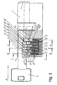
- Fig. 2
- eine teilweise geschnittene Seitenansicht eines erfindungsgemäßen Schließzylinders in einer Stellung, in der der Schlagschlüssel für die Einleitung eines Schlagimpulses vorbereitet worden ist
- Fig. 3
- eine Schnittdarstellung des erfindungsgemäßen Schließzylinders entlang der Linie A - A der
Fig. 2 , wobei die jedoch der Kernstift 66 und der Gehäusestift 86 in der Zuhaltungsbohrung 56 vom Schlagschlüssel radial verschoben worden sind - Fig. 4
- eine Schnittdarstellung des erfindungsgemäßen Schließzylinders entlang der Linie B - B der
Fig. 2 , wobei die jedoch der Kernstift 61 und der Gehäusestift 81 in der Zuhaltungsbohrung 51 vom Schlagschlüssel radial verschoben worden sind - Fig. 5
- eine Schnittdarstellung des erfindungsgemäßen Schließzylinders entlang der Linie C - C der
Fig. 2 , wobei die jedoch der Kernstift 63 und der Gehäusestift 83 in der Zuhaltungsbohrung 53 vom Schlagschlüssel radial verschoben worden sind - In der
Fig. 1 ist ein erfindungsgemäßer Schließzylinder 1 in Form eines Doppelzylinders dargestellt. Dieser weist zwei über einen profilierten Steg 2 miteinander verbundene Zylindergehäuse 3 auf, welche zur drehbaren Lagerung eines Zylinderkerns 4 dienen. Zur Vereinfachung der Zeichnung ist nur die linke Seite des Schließzylinders 1 geschnitten dargestellt und wird nachfolgend beschrieben. Im Zylindergehäuse 3 und Zylinderkern 4 sind mehrere radiale verlaufende Zuhaltungsbohrungen 51 bis 56 befindlich, in denen zur wahlweisen Drehfreigabe (in Verbindung mit dem berechtigten Schlüssel) oder Drehblockierung (nach Abziehen dieses Schlüssels) des Zylinderkerns 4 gegenüber dem Zylindergehäuse 3 jeweils ein Kernstift 61 bis 63 und ein von einer Feder 7 belasteter Gehäusestift 81 bis 83 verschiebbar geführt werden, wobei jeder dieser Kernstifte 61 bis 66 in einem Schlüsselkanal 9 des Zylinderkerns 4 eingreifbar ausgestaltet ist. Die beiden längsten und in den Zuhaltungsbohrungen 54, 56 befindlichen Kernstifte 64, 66 sind an ihrem dem jeweiligen Gehäusestift 84, 86 zugewandten Ende mit einem kegelstumpfförmig ausgeführten Ansatz 10 versehen. Diese Kernstifte 64, 66 arbeiten mit Gehäusestiften 84, 86 zusammen, die zylinderförmig ausgebildet sind somit keinerlei Ansätze oder Aussparungen aufweisen. Auch den weiteren, in den Zuhaltungsbohrungen 51, 52, 55 geführten und gegenüber den Kernstiften 64, 66 kürzer ausgestalteten Kemstiften 61, 62, 66 sind wiederum Gehäusestifte 81, 82, 85 zugeordnet, die ebenfalls eine durchgehend die zylinderförmig Gestalt aufweisen. - Außerdem ist dem in der Zuhaltungsbohrung 53 vorgesehenen Kernstift 63, welcher nicht den längsten der Kernstifte darstellt und damit auch keinen kegelstumpfförmigen Ansatz 10 aufweist, ein Gehäusestift 83 zugeordnet, bei dem zumindest das dem Kernstift 63 zugewandte Ende einen durchmesserkleineren Ansatz 11 aufweist. Auch das andere Ende dieses Gehäusestiftes 83 kann einen ebensolchen durchmesserkleineren Ansatz 11 tragen und weiterhin eine ringförmige Aussparung 12 beinhalten. Dadurch wird gewährleistet, dass diese Stifte ohne zusätzliche Aufwendungen für die automatisierte Montage geeignet sind. Die mittige ringförmige Aussparung täuscht bei Anwendung anderer, bekannter Pickingmethoden eine Schließebene durch Verkanten vor.
- Nachfolgend soll die Funktionsweise des erfindungsgemäßen Schließzylinders erläutert werden:
- Wird ausgehend von
Fig. 1 in dem Schüsselkanal 9 des Zylinderkerns 4 ein nicht dargestellter schließberechtigter Schlüssel eingeführt, so werden die sich berührenden Kernstifte 61 bis 63 und Gehäusestifte 81 bis 86, die an dieser Stelle eine gemeinsame Trennebene 131 bis 136 beinhalten, von den Kerben des Schlüssels in den Zuhaltungsbohrungen 51 bis 56 soweit verschoben, bis jede dieser Trennebenen 131 bis 136 im Bereich der sich zwischen Zylindergehäuse 3 und Zylinderkern 4 befindlichen Kerndrehfuge 14 zu liegen kommt, so dass nunmehr der Zylinderkern 4 gegenüber dem Zylindergehäuse 3 gedreht werden kann. - Wird demgegenüber ein so genannter Schlagschlüssel 15 im Schlüsselkanal 9 des Zylinderkerns 4, wie oben erwähnt, positioniert, so befinden sich die Bauteile des Schließzylinders 1 in einer nach wie vor drehblockierten und in der
Fig. 2 dargestellten Lage. Nachdem durch entsprechende Maßnahmen die gegebene Flucht der Zuhaltungsbohrungen 51 bis 56 im Zylinderkern 4 zu denen im Zylindergehäuse 3 aufgehoben wird, ragt nunmehr eine Kante der jeweiligen Zuhaltungsbohrung für den Gehäusestift 81 bis 86 in die Bewegungsbahn des Kernstiftes 61 bis 66. Ein parallel zur Zylinderkerndrehachse (Pfeil A) auf das komplette System der Kernstifte 61 bis 66, Federn 7 und Gehäusestifte 81 bis 86 wirkender Impuls bewirkt eine radiale, gegen die Kraft der Federn 7 gerichtete Verlagerung aller Kernstifte 61 bis 66 und Gehäusestifte 81 bis 86. Dabei erreichen die Trennebenen 134, 138 zwischen den längsten Kemstiften 64, 66 und den zugehörigen Gehäusestiften 54, 56 den Bereich der sich zwischen Zylindergehäuse 3 und Zylinderkern 4 befindlichen Kerndrehfuge 14 (Fig. 3 ), bevor den kürzeren Kemstiften 61 bis 63, 65 ein Eindringen in die Zuhaltungsbohrungen 51 bis 53, 55 des Zylindergehäuses 3 dadurch verwährt wird, indem der durch das Bauteilspiel in Verbindung mit der auferlegten Vorspannung bedingte geringfügige Versatz der Zuhaltungsbohrungen 81 bis 83, 85 bewirkt, dass die Kernstifte 61 bis 63, 65 an der vorstehenden Kante der jeweiligen Zuhaltungsbohrung 51 bis 53, 55 des Gehäusestiftes 81 bis 83, 85 und damit in der Kerndrehfuge 14 hängen bleiben (Fig. 4 ). Zu diesem Zeitpunkt haben die längsten Kernstifte 64, 63 die Kerndrehfuge 14 bereits gekreuzt und konnten deshalb nicht an der vorstehenden Kante der jeweiligen Zuhaltungsbohrung 54, 56 der Gehäusestifte 84, 86 abgefangen werden, weil diese Kernstifte 64, 68 beim Passieren der Kerndrehfuge 14 durch ihren kegelstumpfförmigen Ansatz 10 zunächst nicht in Kontakt mit der Kante an der Zuhaltungsbohrung 54, 56 gelangen konnten. Dieser Kontakt wird erst dann hergestellt, wenn sich die Kernstifte 64, 66 bereits teilweise in der entsprechenden Zuhaltungsbohrungen 54, 56 des Zylindergehäuses 3 bewegt haben (Fig. 3 ). In dieser Stellung der Kernstifte 64, 68 und Gehäusestifte 84, 86 kann zwar der Zylinderkern 4 soweit ein Stück gedreht werden, bis die längeren Kernstifte 64, 68 an ihrem kegelstumpfförmigen Ansatz 10 verklemmen. Eine selbsthemmende Drehblockierung wird dadurch ermöglicht, dass die Kegelwinkel α 10° bis 40°, vorzugsweise 20° bis 30°, beträgt.
Um zu verhindern, dass durch eine weitergehende Manipulation durch gefühlvolles Reduzieren der aufgebrachten Vorspannung zwischen Zylinderkern 4 und Zylindergehäuse 3, die längeren Kernstifte 64, 66 wieder durch die von der Feder 7 belasteten Gehäusestifte 84, 86 in den Zylinderkern 4 zurückgedrückt werden, wird in zumindest einer der Zuhaltungsbohrungen 53 ein Gehäusestift 83 eingesetzt, bei dem zumindest das dem Kernstift 63 zugewandte Ende einen durchmesserkleineren Ansatz 11 aufweist (Fig. 5 ). Bedingung dafür ist, dass der mit diesem Gehäusestift 83 zusammenwirkende Kernstift 63 keinen kegelförmigen oder durchmesserkleineren Absatz 10 beinhalten darf. Für eine vorteilhafte symmetrische Ausgestaltung dieses Gehäusestiftes 83 kann auch dessen anderes Ende einen ebensolchen durchmesserkleineren Ansatz 11 tragen und weiterhin eine ringförmige Aussparung 12 vorgesehen sein.
Bei dem vorstehend erwähnten Vorspannungsabbau kann der durchmesserkleinere Ansatz 11 des Gehäusestiftes 83 gemäßFig. 5 bereits dann wieder in die Zuhaltungsbohrung 53 des Kemstifts 63 des Zylinderkerns 4 eindringen, während der längere Kernstift 64, 66 den Schließzylinder noch in einer verklemmten Lage hält. - Zur Erzielung der von der Erfindung beabsichtigten Wirkung ist es ausreichend, wenn nur der längste der Kernstifte (z.B. 66) den Ansatz 10 beinhaltet.
-
- 1
- Schließzylinder
- 2
- Steg
- 3
- Zylindergehäuse
- 4
- Zylinderkern
- 51 - 56
- Zuhaltungsbohrung
- 61 - 66
- Kernstift
- 7
- Feder
- 81 - 88
- Gehäusestift
- 9
- Schlüsselkanal
- 10
- kegelförmiger Ansatz
- 11
- durchmesserkleinerer Ansatz
- 12
- Aussparung
- 131 - 136
- Trennebene
- 14
- Kerndrehfuge
- 15
- Schlagschlüssel
- α
- Kegelwinkel
Claims (4)
- Schließzylinder (1) bestehend aus einem Zylindergehäuse (3) mit einem drehbar gelagerten Zylinderkern (4), die mehrere radiale verlaufende Zuhaltungsbohrungen (51 bis 56) beinhalten, in denen zur wahlweisen Drehfreigabe oder Drehblockierung des Zylinderkerns (4) gegenüber dem Zylindergehäuse (3) jeweils ein Kernstift (61 bis 66) und ein von einer Feder belasteter Gehäusestift (81 bis 86) verschiebbar geführt sind, wobei der Kernstift (61 bis 66) in einen Schlüsselkanal (9) des Zylinderkerns (4) eingreifbar ausgestaltet ist und dabei wenigstens einer der Kernstifte (61 bis 66) und einer der Gehäusestifte (81 bis 86) an seinem dem jeweils anderen Stift zugewandten Ende einen durchmesserkleineren Ansatz (11) aufweist,
dadurch gekennzeichnet,
dass wenigstens der längste Kernstift (66) einen sich in Richtung seines Gehäusestifts (86) zugewandten Ende verjüngenden, kegelstumpfförmigen Ansatz (10) aufweist und mit einem Gehäusestift (86) in einer gemeinsamen Zuhaltungsbohrung (56) angeordnet ist, wobei dieser Gehäusestift (86) nicht dem in einer der anderen Zuhaltungsbohrungen (51 bis 55) befindlichen und mit dem durchmesserkleineren Ansatz (11) ausgestatteten, kürzesten Gehäusestift (83) entspricht. - Schließzylinder nach Patentanspruch 1,
dadurch gekennzeichnet,
dass der Ansatz (10) einen Kegelwinkel (α) von 10° bis 40° aufweist. - Schließzylinder nach Patentanspruch 1,
dadurch gekennzeichnet,
dass der Gehäusestift (83) an seinem dem Kernstift (63) abgewandten Ende ebenfalls einen durchmesserkleineren Ansatz (11) aufweist. - Schließzylinder nach Patentanspruch 3,
dadurch gekennzeichnet,
dass der Gehäusestift (83) eine ringförmige Aussparung (12) beinhaltet.
Priority Applications (1)
| Application Number | Priority Date | Filing Date | Title |
|---|---|---|---|
| PL05850161T PL1861569T3 (pl) | 2004-12-23 | 2005-12-16 | Cylinder zamykający |
Applications Claiming Priority (2)
| Application Number | Priority Date | Filing Date | Title |
|---|---|---|---|
| DE102004063395A DE102004063395A1 (de) | 2004-12-23 | 2004-12-23 | Schließzylinder |
| PCT/DE2005/002266 WO2006066549A2 (de) | 2004-12-23 | 2005-12-16 | Schliesszylinder |
Publications (2)
| Publication Number | Publication Date |
|---|---|
| EP1861569A2 EP1861569A2 (de) | 2007-12-05 |
| EP1861569B1 true EP1861569B1 (de) | 2010-02-10 |
Family
ID=36599330
Family Applications (1)
| Application Number | Title | Priority Date | Filing Date |
|---|---|---|---|
| EP05850161A Expired - Lifetime EP1861569B1 (de) | 2004-12-23 | 2005-12-16 | Schliesszylinder |
Country Status (6)
| Country | Link |
|---|---|
| EP (1) | EP1861569B1 (de) |
| AT (1) | ATE457399T1 (de) |
| DE (2) | DE102004063395A1 (de) |
| ES (1) | ES2340944T3 (de) |
| PL (1) | PL1861569T3 (de) |
| WO (1) | WO2006066549A2 (de) |
Family Cites Families (12)
| Publication number | Priority date | Publication date | Assignee | Title |
|---|---|---|---|---|
| US1047483A (en) * | 1912-05-31 | 1912-12-17 | Yale & Towne Mfg Co | Pin-tumbler lock. |
| US1685154A (en) * | 1927-02-17 | 1928-09-25 | American Telephone & Telegraph | Lock |
| US2059129A (en) * | 1933-04-22 | 1936-10-27 | Yale & Towne Mfg Co | Lock |
| DE1876907U (de) * | 1963-06-06 | 1963-08-01 | Karrenberg Fa Wilhelm | Schlosszylinder. |
| DE1876908U (de) * | 1963-06-06 | 1963-08-01 | Karrenberg Fa Wilhelm | Schlosszylinder mit zylindrischen gehaeusestiften. |
| US3590615A (en) * | 1970-02-16 | 1971-07-06 | Eaton Yale & Towne | Antipick lock |
| US3656328A (en) * | 1970-06-03 | 1972-04-18 | Benjamin F Hughes | Lock assembly |
| CS214968B1 (en) * | 1980-06-12 | 1982-06-25 | Pavel Zahradnik | Blocking pin of cylindrical lock |
| IT1286809B1 (it) * | 1996-12-05 | 1998-07-17 | Cisa Spa | Serratura a cilindro con perni antieffrazione perfezionati |
| WO2001048340A1 (en) * | 1999-12-27 | 2001-07-05 | Henrik Dirk Stemmerik | Burglar-proof cylinder lock |
| DE10316742A1 (de) * | 2003-04-04 | 2004-10-28 | IKON GmbH Präzisionstechnik | Schließzylinder |
| DE10316327A1 (de) * | 2003-04-10 | 2004-10-21 | Aug. Winkhaus Gmbh & Co. Kg | Schließzylinder |
-
2004
- 2004-12-23 DE DE102004063395A patent/DE102004063395A1/de not_active Ceased
-
2005
- 2005-12-16 AT AT05850161T patent/ATE457399T1/de active
- 2005-12-16 PL PL05850161T patent/PL1861569T3/pl unknown
- 2005-12-16 ES ES05850161T patent/ES2340944T3/es not_active Expired - Lifetime
- 2005-12-16 WO PCT/DE2005/002266 patent/WO2006066549A2/de not_active Ceased
- 2005-12-16 DE DE502005009016T patent/DE502005009016D1/de not_active Expired - Lifetime
- 2005-12-16 EP EP05850161A patent/EP1861569B1/de not_active Expired - Lifetime
Also Published As
| Publication number | Publication date |
|---|---|
| WO2006066549A3 (de) | 2007-01-18 |
| EP1861569A2 (de) | 2007-12-05 |
| PL1861569T3 (pl) | 2010-07-30 |
| ATE457399T1 (de) | 2010-02-15 |
| WO2006066549A2 (de) | 2006-06-29 |
| ES2340944T3 (es) | 2010-06-11 |
| DE502005009016D1 (de) | 2010-03-25 |
| DE102004063395A1 (de) | 2006-07-13 |
Similar Documents
| Publication | Publication Date | Title |
|---|---|---|
| DE69417530T2 (de) | Gegen Einbruch widerstandsfähiges Zylinderschloss | |
| AT513607B1 (de) | Zylinderschloss | |
| DE2717799A1 (de) | Zylinderschloss | |
| EP1632625B1 (de) | Drehschliesszylinder für ein Sicherheitsschloss | |
| DE102011015314A1 (de) | Schließzylinder | |
| DE4035934A1 (de) | Aus schluessel und schliesszylinder bestehende schliessvorrichtung | |
| DE202016003806U1 (de) | Schlüssel für einen Schließzylinder und Schließvorrichtung | |
| EP2218850A1 (de) | Kupplungseinrichtung für einen zwei Zylinderkerne beinhaltenden Doppelschließzylinder mit Not- und Gefahrenfunktion | |
| EP3561203A1 (de) | Hangschloss zum sichern eines schalters | |
| EP2166179A1 (de) | Schließzylinder, insbesondere für ein Türschloss | |
| EP2619387A1 (de) | Drehschliesszylinder und sicherheitsschlüssel | |
| DE202019102154U1 (de) | Modulartig aufgebauter Schließzylinder | |
| DE102005037194B4 (de) | Schließzylinder, insbesondere Profilzylinder, für eine Schließvorrichtung wie z.B. ein Türschloss | |
| DE102009037682B4 (de) | Schließzylinder | |
| EP1861569A2 (de) | Schliesszylinder | |
| EP1700980B1 (de) | Drehschliesszylinder für ein Sicherheitsschloss | |
| EP1760229B1 (de) | Schliesszylinder, insbesondere Profilzylinder, für eine Schliessvorrichtung wie z.B. ein Türschloss | |
| DE29722567U1 (de) | Stiftzylinderschloß | |
| EP1826340A1 (de) | Zylinderschloss mit Sperrscheiben | |
| EP0979913A2 (de) | Kopplungseinrichtung für ein Zylinderschloss | |
| EP3228787A1 (de) | Verbesserter schliesszylinder | |
| EP4571018A1 (de) | Schliessvorrichtung mit einer kurbel, welche von schliesszylindern mit mitnehmerplättchen angesteuert wird | |
| EP3095931B1 (de) | Schliesszylinder und schliesssystem mit einem solchen schliesszylinder | |
| EP2952656B1 (de) | Profilzylinder mit einem zylindergehäuse | |
| AT511401B1 (de) | Zylinderschloss mit mehrteiligem gehäusestift |
Legal Events
| Date | Code | Title | Description |
|---|---|---|---|
| PUAI | Public reference made under article 153(3) epc to a published international application that has entered the european phase |
Free format text: ORIGINAL CODE: 0009012 |
|
| 17P | Request for examination filed |
Effective date: 20070914 |
|
| AK | Designated contracting states |
Kind code of ref document: A2 Designated state(s): AT BE BG CH CY CZ DE DK EE ES FI FR GB GR HU IE IS IT LI LT LU LV MC NL PL PT RO SE SI SK TR |
|
| DAX | Request for extension of the european patent (deleted) | ||
| 17Q | First examination report despatched |
Effective date: 20080630 |
|
| RAP1 | Party data changed (applicant data changed or rights of an application transferred) |
Owner name: ABUS PFAFFENHAIN GMBH |
|
| GRAP | Despatch of communication of intention to grant a patent |
Free format text: ORIGINAL CODE: EPIDOSNIGR1 |
|
| GRAS | Grant fee paid |
Free format text: ORIGINAL CODE: EPIDOSNIGR3 |
|
| GRAA | (expected) grant |
Free format text: ORIGINAL CODE: 0009210 |
|
| AK | Designated contracting states |
Kind code of ref document: B1 Designated state(s): AT BE BG CH CY CZ DE DK EE ES FI FR GB GR HU IE IS IT LI LT LU LV MC NL PL PT RO SE SI SK TR |
|
| REG | Reference to a national code |
Ref country code: GB Ref legal event code: FG4D Free format text: NOT ENGLISH |
|
| REG | Reference to a national code |
Ref country code: CH Ref legal event code: EP |
|
| REG | Reference to a national code |
Ref country code: IE Ref legal event code: FG4D |
|
| REF | Corresponds to: |
Ref document number: 502005009016 Country of ref document: DE Date of ref document: 20100325 Kind code of ref document: P |
|
| REG | Reference to a national code |
Ref country code: NL Ref legal event code: T3 |
|
| REG | Reference to a national code |
Ref country code: ES Ref legal event code: FG2A Ref document number: 2340944 Country of ref document: ES Kind code of ref document: T3 Ref country code: GR Ref legal event code: EP Ref document number: 20100401075 Country of ref document: GR |
|
| LTIE | Lt: invalidation of european patent or patent extension |
Effective date: 20100210 |
|
| PG25 | Lapsed in a contracting state [announced via postgrant information from national office to epo] |
Ref country code: LT Free format text: LAPSE BECAUSE OF FAILURE TO SUBMIT A TRANSLATION OF THE DESCRIPTION OR TO PAY THE FEE WITHIN THE PRESCRIBED TIME-LIMIT Effective date: 20100210 Ref country code: IS Free format text: LAPSE BECAUSE OF FAILURE TO SUBMIT A TRANSLATION OF THE DESCRIPTION OR TO PAY THE FEE WITHIN THE PRESCRIBED TIME-LIMIT Effective date: 20100610 Ref country code: PT Free format text: LAPSE BECAUSE OF FAILURE TO SUBMIT A TRANSLATION OF THE DESCRIPTION OR TO PAY THE FEE WITHIN THE PRESCRIBED TIME-LIMIT Effective date: 20100611 |
|
| REG | Reference to a national code |
Ref country code: PL Ref legal event code: T3 |
|
| PG25 | Lapsed in a contracting state [announced via postgrant information from national office to epo] |
Ref country code: SI Free format text: LAPSE BECAUSE OF FAILURE TO SUBMIT A TRANSLATION OF THE DESCRIPTION OR TO PAY THE FEE WITHIN THE PRESCRIBED TIME-LIMIT Effective date: 20100210 Ref country code: LV Free format text: LAPSE BECAUSE OF FAILURE TO SUBMIT A TRANSLATION OF THE DESCRIPTION OR TO PAY THE FEE WITHIN THE PRESCRIBED TIME-LIMIT Effective date: 20100210 |
|
| PG25 | Lapsed in a contracting state [announced via postgrant information from national office to epo] |
Ref country code: CY Free format text: LAPSE BECAUSE OF FAILURE TO SUBMIT A TRANSLATION OF THE DESCRIPTION OR TO PAY THE FEE WITHIN THE PRESCRIBED TIME-LIMIT Effective date: 20100210 Ref country code: EE Free format text: LAPSE BECAUSE OF FAILURE TO SUBMIT A TRANSLATION OF THE DESCRIPTION OR TO PAY THE FEE WITHIN THE PRESCRIBED TIME-LIMIT Effective date: 20100210 Ref country code: RO Free format text: LAPSE BECAUSE OF FAILURE TO SUBMIT A TRANSLATION OF THE DESCRIPTION OR TO PAY THE FEE WITHIN THE PRESCRIBED TIME-LIMIT Effective date: 20100210 Ref country code: SE Free format text: LAPSE BECAUSE OF FAILURE TO SUBMIT A TRANSLATION OF THE DESCRIPTION OR TO PAY THE FEE WITHIN THE PRESCRIBED TIME-LIMIT Effective date: 20100210 |
|
| PG25 | Lapsed in a contracting state [announced via postgrant information from national office to epo] |
Ref country code: BG Free format text: LAPSE BECAUSE OF FAILURE TO SUBMIT A TRANSLATION OF THE DESCRIPTION OR TO PAY THE FEE WITHIN THE PRESCRIBED TIME-LIMIT Effective date: 20100510 Ref country code: SK Free format text: LAPSE BECAUSE OF FAILURE TO SUBMIT A TRANSLATION OF THE DESCRIPTION OR TO PAY THE FEE WITHIN THE PRESCRIBED TIME-LIMIT Effective date: 20100210 Ref country code: CZ Free format text: LAPSE BECAUSE OF FAILURE TO SUBMIT A TRANSLATION OF THE DESCRIPTION OR TO PAY THE FEE WITHIN THE PRESCRIBED TIME-LIMIT Effective date: 20100210 |
|
| PLBE | No opposition filed within time limit |
Free format text: ORIGINAL CODE: 0009261 |
|
| STAA | Information on the status of an ep patent application or granted ep patent |
Free format text: STATUS: NO OPPOSITION FILED WITHIN TIME LIMIT |
|
| 26N | No opposition filed |
Effective date: 20101111 |
|
| PG25 | Lapsed in a contracting state [announced via postgrant information from national office to epo] |
Ref country code: DK Free format text: LAPSE BECAUSE OF FAILURE TO SUBMIT A TRANSLATION OF THE DESCRIPTION OR TO PAY THE FEE WITHIN THE PRESCRIBED TIME-LIMIT Effective date: 20100210 |
|
| PG25 | Lapsed in a contracting state [announced via postgrant information from national office to epo] |
Ref country code: MC Free format text: LAPSE BECAUSE OF NON-PAYMENT OF DUE FEES Effective date: 20101231 |
|
| REG | Reference to a national code |
Ref country code: CH Ref legal event code: PL |
|
| PG25 | Lapsed in a contracting state [announced via postgrant information from national office to epo] |
Ref country code: LI Free format text: LAPSE BECAUSE OF NON-PAYMENT OF DUE FEES Effective date: 20101231 Ref country code: CH Free format text: LAPSE BECAUSE OF NON-PAYMENT OF DUE FEES Effective date: 20101231 |
|
| PG25 | Lapsed in a contracting state [announced via postgrant information from national office to epo] |
Ref country code: LU Free format text: LAPSE BECAUSE OF NON-PAYMENT OF DUE FEES Effective date: 20101216 Ref country code: HU Free format text: LAPSE BECAUSE OF FAILURE TO SUBMIT A TRANSLATION OF THE DESCRIPTION OR TO PAY THE FEE WITHIN THE PRESCRIBED TIME-LIMIT Effective date: 20100811 |
|
| PG25 | Lapsed in a contracting state [announced via postgrant information from national office to epo] |
Ref country code: TR Free format text: LAPSE BECAUSE OF FAILURE TO SUBMIT A TRANSLATION OF THE DESCRIPTION OR TO PAY THE FEE WITHIN THE PRESCRIBED TIME-LIMIT Effective date: 20100210 |
|
| PGFP | Annual fee paid to national office [announced via postgrant information from national office to epo] |
Ref country code: FI Payment date: 20121214 Year of fee payment: 8 Ref country code: IE Payment date: 20121213 Year of fee payment: 8 |
|
| PGFP | Annual fee paid to national office [announced via postgrant information from national office to epo] |
Ref country code: ES Payment date: 20121217 Year of fee payment: 8 Ref country code: PL Payment date: 20121207 Year of fee payment: 8 Ref country code: IT Payment date: 20121219 Year of fee payment: 8 Ref country code: GR Payment date: 20121221 Year of fee payment: 8 Ref country code: GB Payment date: 20121218 Year of fee payment: 8 |
|
| PGFP | Annual fee paid to national office [announced via postgrant information from national office to epo] |
Ref country code: AT Payment date: 20121214 Year of fee payment: 8 Ref country code: NL Payment date: 20121217 Year of fee payment: 8 |
|
| PGFP | Annual fee paid to national office [announced via postgrant information from national office to epo] |
Ref country code: BE Payment date: 20121217 Year of fee payment: 8 Ref country code: FR Payment date: 20130123 Year of fee payment: 8 |
|
| BERE | Be: lapsed |
Owner name: ABUS PFAFFENHAIN G.M.B.H. Effective date: 20131231 |
|
| REG | Reference to a national code |
Ref country code: NL Ref legal event code: V1 Effective date: 20140701 |
|
| REG | Reference to a national code |
Ref country code: AT Ref legal event code: MM01 Ref document number: 457399 Country of ref document: AT Kind code of ref document: T Effective date: 20131216 |
|
| GBPC | Gb: european patent ceased through non-payment of renewal fee |
Effective date: 20131216 |
|
| PG25 | Lapsed in a contracting state [announced via postgrant information from national office to epo] |
Ref country code: FI Free format text: LAPSE BECAUSE OF NON-PAYMENT OF DUE FEES Effective date: 20131216 |
|
| REG | Reference to a national code |
Ref country code: GR Ref legal event code: ML Ref document number: 20100401075 Country of ref document: GR Effective date: 20140702 |
|
| REG | Reference to a national code |
Ref country code: IE Ref legal event code: MM4A |
|
| REG | Reference to a national code |
Ref country code: FR Ref legal event code: ST Effective date: 20140829 |
|
| PG25 | Lapsed in a contracting state [announced via postgrant information from national office to epo] |
Ref country code: GR Free format text: LAPSE BECAUSE OF NON-PAYMENT OF DUE FEES Effective date: 20140702 Ref country code: IE Free format text: LAPSE BECAUSE OF NON-PAYMENT OF DUE FEES Effective date: 20131216 Ref country code: NL Free format text: LAPSE BECAUSE OF NON-PAYMENT OF DUE FEES Effective date: 20140701 Ref country code: BE Free format text: LAPSE BECAUSE OF NON-PAYMENT OF DUE FEES Effective date: 20131231 |
|
| PG25 | Lapsed in a contracting state [announced via postgrant information from national office to epo] |
Ref country code: FR Free format text: LAPSE BECAUSE OF NON-PAYMENT OF DUE FEES Effective date: 20131231 Ref country code: AT Free format text: LAPSE BECAUSE OF NON-PAYMENT OF DUE FEES Effective date: 20131216 Ref country code: GB Free format text: LAPSE BECAUSE OF NON-PAYMENT OF DUE FEES Effective date: 20131216 |
|
| PG25 | Lapsed in a contracting state [announced via postgrant information from national office to epo] |
Ref country code: PL Free format text: LAPSE BECAUSE OF NON-PAYMENT OF DUE FEES Effective date: 20131216 |
|
| REG | Reference to a national code |
Ref country code: PL Ref legal event code: LAPE |
|
| REG | Reference to a national code |
Ref country code: ES Ref legal event code: FD2A Effective date: 20150709 |
|
| PG25 | Lapsed in a contracting state [announced via postgrant information from national office to epo] |
Ref country code: ES Free format text: LAPSE BECAUSE OF NON-PAYMENT OF DUE FEES Effective date: 20131217 |
|
| PG25 | Lapsed in a contracting state [announced via postgrant information from national office to epo] |
Ref country code: IT Free format text: LAPSE BECAUSE OF NON-PAYMENT OF DUE FEES Effective date: 20131231 |
|
| PG25 | Lapsed in a contracting state [announced via postgrant information from national office to epo] |
Ref country code: IT Free format text: LAPSE BECAUSE OF NON-PAYMENT OF DUE FEES Effective date: 20131216 |
|
| PGFP | Annual fee paid to national office [announced via postgrant information from national office to epo] |
Ref country code: DE Payment date: 20161220 Year of fee payment: 12 |
|
| REG | Reference to a national code |
Ref country code: DE Ref legal event code: R119 Ref document number: 502005009016 Country of ref document: DE |
|
| PG25 | Lapsed in a contracting state [announced via postgrant information from national office to epo] |
Ref country code: DE Free format text: LAPSE BECAUSE OF NON-PAYMENT OF DUE FEES Effective date: 20180703 |