EP1860755A2 - Magnetaufnahmevorrichtung - Google Patents
Magnetaufnahmevorrichtung Download PDFInfo
- Publication number
- EP1860755A2 EP1860755A2 EP07010082A EP07010082A EP1860755A2 EP 1860755 A2 EP1860755 A2 EP 1860755A2 EP 07010082 A EP07010082 A EP 07010082A EP 07010082 A EP07010082 A EP 07010082A EP 1860755 A2 EP1860755 A2 EP 1860755A2
- Authority
- EP
- European Patent Office
- Prior art keywords
- magnet
- pole piece
- permanent magnet
- arrangement according
- rotor
- Prior art date
- Legal status (The legal status is an assumption and is not a legal conclusion. Google has not performed a legal analysis and makes no representation as to the accuracy of the status listed.)
- Granted
Links
- 239000000969 carrier Substances 0.000 claims abstract description 22
- 239000000696 magnetic material Substances 0.000 claims abstract description 13
- 229910000831 Steel Inorganic materials 0.000 claims abstract description 4
- 239000000463 material Substances 0.000 claims abstract description 4
- 229910001220 stainless steel Inorganic materials 0.000 claims abstract description 4
- 239000010935 stainless steel Substances 0.000 claims abstract description 4
- 239000010959 steel Substances 0.000 claims abstract description 4
- 230000000295 complement effect Effects 0.000 claims description 3
- 239000003822 epoxy resin Substances 0.000 description 4
- 229920000647 polyepoxide Polymers 0.000 description 4
- 239000000853 adhesive Substances 0.000 description 3
- 230000001070 adhesive effect Effects 0.000 description 3
- 239000000945 filler Substances 0.000 description 2
- 230000004907 flux Effects 0.000 description 2
- 238000004519 manufacturing process Methods 0.000 description 2
- 239000007769 metal material Substances 0.000 description 2
- 238000000034 method Methods 0.000 description 2
- 229920000728 polyester Polymers 0.000 description 2
- 229920000642 polymer Polymers 0.000 description 2
- 239000004814 polyurethane Substances 0.000 description 2
- 229920002635 polyurethane Polymers 0.000 description 2
- 229920002430 Fibre-reinforced plastic Polymers 0.000 description 1
- 238000010276 construction Methods 0.000 description 1
- 239000011151 fibre-reinforced plastic Substances 0.000 description 1
- 230000007774 longterm Effects 0.000 description 1
- 230000002093 peripheral effect Effects 0.000 description 1
Images

Classifications
-
- H—ELECTRICITY
- H02—GENERATION; CONVERSION OR DISTRIBUTION OF ELECTRIC POWER
- H02K—DYNAMO-ELECTRIC MACHINES
- H02K1/00—Details of the magnetic circuit
- H02K1/06—Details of the magnetic circuit characterised by the shape, form or construction
- H02K1/22—Rotating parts of the magnetic circuit
- H02K1/27—Rotor cores with permanent magnets
- H02K1/2706—Inner rotors
- H02K1/272—Inner rotors the magnetisation axis of the magnets being perpendicular to the rotor axis
- H02K1/274—Inner rotors the magnetisation axis of the magnets being perpendicular to the rotor axis the rotor consisting of two or more circumferentially positioned magnets
- H02K1/2753—Inner rotors the magnetisation axis of the magnets being perpendicular to the rotor axis the rotor consisting of two or more circumferentially positioned magnets the rotor consisting of magnets or groups of magnets arranged with alternating polarity
- H02K1/278—Surface mounted magnets; Inset magnets
-
- H—ELECTRICITY
- H02—GENERATION; CONVERSION OR DISTRIBUTION OF ELECTRIC POWER
- H02K—DYNAMO-ELECTRIC MACHINES
- H02K1/00—Details of the magnetic circuit
- H02K1/06—Details of the magnetic circuit characterised by the shape, form or construction
- H02K1/22—Rotating parts of the magnetic circuit
- H02K1/27—Rotor cores with permanent magnets
- H02K1/2786—Outer rotors
-
- H—ELECTRICITY
- H02—GENERATION; CONVERSION OR DISTRIBUTION OF ELECTRIC POWER
- H02K—DYNAMO-ELECTRIC MACHINES
- H02K1/00—Details of the magnetic circuit
- H02K1/06—Details of the magnetic circuit characterised by the shape, form or construction
- H02K1/22—Rotating parts of the magnetic circuit
- H02K1/28—Means for mounting or fastening rotating magnetic parts on to, or to, the rotor structures
- H02K1/30—Means for mounting or fastening rotating magnetic parts on to, or to, the rotor structures using intermediate parts, e.g. spiders
-
- H—ELECTRICITY
- H02—GENERATION; CONVERSION OR DISTRIBUTION OF ELECTRIC POWER
- H02K—DYNAMO-ELECTRIC MACHINES
- H02K15/00—Methods or apparatus specially adapted for manufacturing, assembling, maintaining or repairing of dynamo-electric machines
- H02K15/02—Methods or apparatus specially adapted for manufacturing, assembling, maintaining or repairing of dynamo-electric machines of stator or rotor bodies
- H02K15/03—Methods or apparatus specially adapted for manufacturing, assembling, maintaining or repairing of dynamo-electric machines of stator or rotor bodies having permanent magnets
-
- H—ELECTRICITY
- H02—GENERATION; CONVERSION OR DISTRIBUTION OF ELECTRIC POWER
- H02K—DYNAMO-ELECTRIC MACHINES
- H02K7/00—Arrangements for handling mechanical energy structurally associated with dynamo-electric machines, e.g. structural association with mechanical driving motors or auxiliary dynamo-electric machines
- H02K7/18—Structural association of electric generators with mechanical driving motors, e.g. with turbines
- H02K7/1807—Rotary generators
- H02K7/1823—Rotary generators structurally associated with turbines or similar engines
- H02K7/183—Rotary generators structurally associated with turbines or similar engines wherein the turbine is a wind turbine
- H02K7/1838—Generators mounted in a nacelle or similar structure of a horizontal axis wind turbine
Definitions
- the present invention relates to a magnet retaining arrangement, and in particular to an arrangement for retaining permanent magnets on the outside of a permanent magnet rotor.
- EP 1309067 discloses a permanent magnet retaining arrangement that is suitable for high speed motors.
- the arrangement includes a rotor where a spaced array of pole pieces made of a laminated magnetic material are mechanically secured to the rim of the rotor by key members held by screws.
- a magnet is held in position between each pair of pole pieces by a slot wedge that is made of a non-magnetic material.
- the slot wedge includes grooves in its opposite edges for receiving projections formed on the adjacent pole pieces.
- An inverted U-shaped retainer is located in the space between the magnet and its associated slot wedge to enclose the magnet during high speed rotation of the rotor.
- the retainer is made of a non-magnetic material and has inner surfaces that conform to the rectangular periphery of the magnet, a radially outer surface that engages with the radially inner surface of the slot wedge and circumferential outer surfaces that conform to corresponding surfaces on the adjacent pole pieces.
- a circumferential outer wrap of fibre-reinforced polymer material surrounds the entire peripheral surface of the rotor structure.
- This method of fixing is only really appropriate for rotors with pole pieces and magnets arranged so that the flux in the magnets passes predominantly in the circumferential direction.
- a disadvantage of this method is the need for high accuracy in the manufacture of the U-shaped retainers.
- the present invention provides a permanent magnet rotor arrangement comprising a rotor having a rim, a circumferential array of magnet carriers affixed to the rim of the rotor, each magnet carrier having a surface, an inverted U-shaped pole piece retainer made of non-magnetic material affixed to each magnet carrier and formed with a channel, and at least one pole piece made of permanent magnet material located adjacent to the surface of each magnet carrier and in the channel formed in its associated pole piece retainer.
- the rotor arrangement can be such that the rotor is located within a fixed stator.
- the circumferential array of magnet carriers is preferably affixed to a radially outer rim of the rotor and each pole piece is preferably located adjacent to a radially outer surface of each magnet carrier.
- the rotor arrangement can also be such that the rotor is located outside a fixed stator.
- the circumferential array of magnet carriers is preferably affixed to a radially inner rim of the rotor and each pole piece is preferably located adjacent to a radially inner surface of each magnet carrier.
- Clearances between the pole pieces and the pole piece retainers can be filled with any suitable non-metallic material such as epoxy resin, with or without a filler, polymers such as polyurethane and polyesters, and vacuum impregnated fibres or felt, for example.
- suitable non-metallic material such as epoxy resin, with or without a filler, polymers such as polyurethane and polyesters, and vacuum impregnated fibres or felt, for example.
- the rotor arrangement of the present invention is particularly suitable for rotors in which the flux passes through the pole pieces predominantly in the radial direction.
- the advantages of the rotor arrangement are simplicity of construction, the ability to pre-assemble complete pole arrangements and the ease with which the pole pieces may be removed and replaced.
- the requirements for the dimensional tolerances of the pole piece retainers are modest resulting in low manufacturing costs.
- Each magnet carrier is preferably located in the channel of its associated pole piece retainer.
- Each magnet carrier and its associated pole piece retainer preferably extend axially along the outer rim of the rotor.
- An axial array of pole pieces of magnetic material is preferably located adjacent to the radially outer surface of each magnet carrier and in the channel formed in its associated pole piece retainer.
- the pole pieces associated with each magnet carrier and pole piece retainer can be located in abutment with each other in the axial direction.
- the magnet carriers are preferably made of magnetic material such as steel, for example.
- Each magnet carrier can be mounted in a recess in the radially outer rim of the rotor.
- the magnet carriers can be affixed to the radially outer rim of the rotor using any suitable means. Mechanical fixings such as screws or bolts can be used.
- the magnet carriers can also be adhesively bonded to the radially outer rim of the rotor.
- the magnet carriers can also be shaped to allow them to be affixed to the radially outer rim of the rotor.
- One way of achieving this would be to provide a radially inner part of each magnet carrier with a dovetail or shaped projection that can be received in one of a circumferential array of complementary recesses in the radially outer rim of the rotor.
- the magnet carriers could then be secured in position within the recesses using known fixings such as tapered keys, for example.
- the pole piece retainers are preferably made of a non-magnetic material such as stainless steel or glass-reinforced epoxy resin, for example.
- Each pole piece retainer can be affixed to its associated magnet carrier using any suitable means.
- the pole piece retainer can be affixed using mechanical fixings such as screws or bolts.
- the pole piece retainer can also be adhesively bonded or welded directly to its associated magnet carrier or clipped into position. In the latter case, it is possible for each pole piece retainer to be affixed to its associated magnet carrier by engaging a part of the pole piece retainer with or behind a part of the magnet carrier.
- a combination of one or more fixing means can be used.
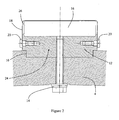
- a permanent magnet rotor arrangement for a low-speed large-diameter electrical generator includes a rotor 2 having an outer rim 4 that is mounted to rotate within a fixed stator 6 having a circumferential array of slots 8 formed in its radially inner surface.
- the radially outer surface of the rim 4 includes a circumferential array of axially-extending recesses 10.
- An axially-extending bar or magnet carrier 12 made of a magnetic material such as steel is located in each of the recesses.
- Each magnet carrier 12 is secured to the rim 4 of the rotor 2 by a series of axially spaced screws 14 that extend radially through apertures in the rim into screw-threaded apertures in the magnet carrier.
- Other ways of securing the magnet carriers 12 to the rim 4 of the rotor can be used as appropriate.
- an axial array of permanent magnet pole pieces 16 are positioned on top of each of the magnet carriers 12 and are held in position by an axially-extending pole piece retainer 18.
- the pole pieces 16 sit in a shallow recess formed in the radially outer surface of the underlying magnet carrier 12 and are in abutment with each other in the axial direction.
- Each pole piece retainer 18 has an inverted U-shape configuration such that it has a circumferentially extending surface 18a that is separated from the radially inner surface of the stator 6 by an air gap.
- Each pole piece retainer 18 also includes two radially extending sidewalls 18b that are secured to the associated magnet carrier 12 on both sides by a series of axially spaced screws 20.
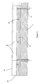
- each sidewall 18b of the pole piece retainer 18 may terminate in an inwardly facing flange that in use lies between the magnet carrier and the radially outer surface of the rim.
- the surfaces 18b extend alongside the radially outer surfaces of the axial array of pole pieces 16 and radially inner parts of the sidewalls 18b lie against the side surfaces of the magnet carrier 12.
- the two sidewalls 18b therefore define an axially extending channel 24 that is filled by the magnet carrier 12 and the axial array of pole pieces 16.
- Radially outer parts of the sidewalls 18b that are aligned with the pole pieces 16 are separated from the side surfaces of the pole pieces by a small gap 26.
- This gap 26 accommodates the radius in the corner of each pole piece retainer 18 and minimises the need to chamfer the corners of the pole pieces 16.
- the gap 26 is filled with any suitable non-metallic material such as epoxy resin, with or without a filler, polymers such as polyurethane and polyesters, and vacuum impregnated fibres or felt, for example.
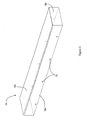
- the pole pieces 16 are bonded to the magnet carriers 12 with an adhesive but the long-term efficacy of this is not guaranteed and one of the purposes of the pole piece retainers is therefore to retain the magnets that become detached from the magnet carriers.
- Each pole is usually formed from an axial array of pole pieces 16 that would tend to move apart axially if the adhesive bond with the associated magnet carrier 12 failed (or if the assembly were made without the use of adhesive at all).
- the pole piece retainers 18 may therefore have closed ends (one of which 28 is shown in Figure 4) to prevent this movement.
- end-stops can be incorporated into the magnet carriers 12, or bolted or otherwise secured to either the magnet carriers or the rim of the rotor 2.
- Other options for preventing axial movement of the pole pieces 16 relative to the associated magnet carrier 12 and pole piece retainer 18 can be employed.
- the pole piece retainers 18 can be formed from any non-magnetic material such as stainless steel or glass-reinforced epoxy resin, for example.
- the pole piece retainer 18 can be adhered, welded, clipped or otherwise secured to its associated magnet carrier 12 without the need for the screws.
- the free ends of the sidewalls 18b can be adapted to be engaged with complementary features such as recesses formed on the side surfaces of the magnet carrier 12.
Landscapes
- Engineering & Computer Science (AREA)
- Power Engineering (AREA)
- Permanent Field Magnets Of Synchronous Machinery (AREA)
- Dynamo-Electric Clutches, Dynamo-Electric Brakes (AREA)
- Magnetic Bearings And Hydrostatic Bearings (AREA)
- Audible-Bandwidth Dynamoelectric Transducers Other Than Pickups (AREA)
Applications Claiming Priority (1)
| Application Number | Priority Date | Filing Date | Title |
|---|---|---|---|
| GB0610573A GB2438443A (en) | 2006-05-27 | 2006-05-27 | Rotor magnet retaining arrangement suitable for low-speed large-diameter electrical generators |
Publications (4)
| Publication Number | Publication Date |
|---|---|
| EP1860755A2 true EP1860755A2 (de) | 2007-11-28 |
| EP1860755A3 EP1860755A3 (de) | 2010-08-18 |
| EP1860755B1 EP1860755B1 (de) | 2011-09-28 |
| EP1860755B2 EP1860755B2 (de) | 2021-03-17 |
Family
ID=36687867
Family Applications (1)
| Application Number | Title | Priority Date | Filing Date |
|---|---|---|---|
| EP07010082.1A Active EP1860755B2 (de) | 2006-05-27 | 2007-05-21 | Magnetaufnahmevorrichtung |
Country Status (9)
| Country | Link |
|---|---|
| US (2) | US7768169B2 (de) |
| EP (1) | EP1860755B2 (de) |
| CN (1) | CN101090213B (de) |
| AT (1) | ATE526717T1 (de) |
| CA (1) | CA2588484A1 (de) |
| DK (1) | DK1860755T3 (de) |
| ES (1) | ES2374452T3 (de) |
| GB (1) | GB2438443A (de) |
| NO (1) | NO20072686L (de) |
Cited By (20)
| Publication number | Priority date | Publication date | Assignee | Title |
|---|---|---|---|---|
| WO2008046780A3 (de) * | 2006-10-17 | 2008-08-21 | Siemens Ag | Magnetmodul für eine permanentmagneterregte elektrische maschine |
| WO2009068736A1 (en) * | 2007-11-30 | 2009-06-04 | Neorem Magnets Oy | Surface-mountable permanent magnet element |
| WO2011039143A2 (de) | 2009-09-29 | 2011-04-07 | Siemens Aktiengesellschaft | Rotor |
| EP2348612A1 (de) * | 2010-01-20 | 2011-07-27 | Siemens Aktiengesellschaft | Magnetischer Komponententeil für eine Rotoranordnung |
| EP2360816A1 (de) | 2010-02-24 | 2011-08-24 | Indar Electric S.L. | Anordnung zur Montage von Magneten auf einem laminierten Rotorpaket |
| WO2011100987A1 (en) | 2010-02-16 | 2011-08-25 | Siemens Aktiengesellschaft | Method for assembling part of a generator, generator and wind turbine |
| EP2410633A1 (de) | 2010-07-20 | 2012-01-25 | Siemens Aktiengesellschaft | Permanentmagnetrotor und dessen Herstellungsmethode |
| WO2012031923A1 (de) * | 2010-09-08 | 2012-03-15 | Siemens Aktiengesellschaft | Rotor für eine elektrische maschine |
| WO2012034713A2 (en) | 2010-09-15 | 2012-03-22 | Siemens Aktiengesellschaft | A pole piece for an electric machine and a method for assembling a pole piece |
| DE102010041585A1 (de) | 2010-09-29 | 2012-03-29 | Siemens Aktiengesellschaft | Rotor einer elektrischen Maschine |
| DE102010041593A1 (de) | 2010-09-29 | 2012-03-29 | Siemens Aktiengesellschaft | Magnetpolabdeckung einer elektrischen Maschine |
| CN102439822A (zh) * | 2008-12-17 | 2012-05-02 | 斯维奇传动系统有限公司 | 用于电机的永磁模块 |
| EP2506400A1 (de) | 2011-04-01 | 2012-10-03 | Converteam Technology Ltd | Dauermagnetaufnahmen eines Läufers |
| US8339005B2 (en) | 2010-02-24 | 2012-12-25 | Indar Electric S.L. | Assembly and method for mounting magnets on a steel sheet rotor pack |
| EP2555381A1 (de) * | 2011-08-01 | 2013-02-06 | Siemens Aktiengesellschaft | Dauermagnetanordnung mit geflanschter Abdeckung und Verfahren zur Befestigung eines Dauermagneten auf einer Grundplatte |
| EP2555382A1 (de) * | 2011-08-01 | 2013-02-06 | Siemens Aktiengesellschaft | Dauermagnetanordnung und Verfahren zur Befestigung eines Dauermagneten auf einer Grundplatte |
| EP2930825A1 (de) * | 2014-04-11 | 2015-10-14 | Siemens Aktiengesellschaft | Montage von Permanentmagneten auf einem Rotor einer elektrischen Maschine |
| EP3179606A1 (de) * | 2015-12-08 | 2017-06-14 | ABB Schweiz AG | Rotor für eine elektrische maschine |
| US9973045B2 (en) | 2011-05-11 | 2018-05-15 | Ge Renewable Technologies Wind B.V. | Generator rotor, assembly method and related insertion tool |
| EP4160885A1 (de) | 2021-10-04 | 2023-04-05 | GE Energy Power Conversion Technology Ltd | Rotoren für elektrische maschinen |
Families Citing this family (32)
| Publication number | Priority date | Publication date | Assignee | Title |
|---|---|---|---|---|
| FI117582B (fi) * | 2004-12-23 | 2006-11-30 | Abb Oy | Kestomagneettikoneen roottorirakenne |
| EP1835188B1 (de) * | 2006-03-16 | 2009-10-28 | Nexans | Hochtemperatursupraleitendes Magnetlager |
| GB2438443A (en) * | 2006-05-27 | 2007-11-28 | Converteam Ltd | Rotor magnet retaining arrangement suitable for low-speed large-diameter electrical generators |
| US7973444B2 (en) * | 2007-04-27 | 2011-07-05 | Remy Technologies, Inc. | Electric machine and rotor for the same |
| USRE46449E1 (en) | 2007-07-09 | 2017-06-20 | Clearwater Holdings, Ltd. | Electromagnetic machine with independent removable coils, modular parts and self sustained passive magnetic bearing |
| CN101640457B (zh) * | 2008-07-31 | 2011-03-30 | 上海电气集团上海电机厂有限公司 | 交交变频轧钢电机转子结构及其磁极安装方法 |
| EP2340602B1 (de) | 2008-09-26 | 2019-01-02 | Clearwater Holdings, Ltd. | Permanentmagnetisch operierende maschine |
| US9515529B2 (en) | 2009-08-18 | 2016-12-06 | Northern Power Systems, Inc. | Method and apparatus for permanent magnet attachment in an electromechanical machine |
| US8664819B2 (en) * | 2009-08-18 | 2014-03-04 | Northern Power Systems Utility Scale, Inc. | Method and apparatus for permanent magnet attachment in an electromechanical machine |
| US8063531B2 (en) | 2010-01-11 | 2011-11-22 | Converteam Technology Ltd. | Permanent magnet arrangement for an electrical machine |
| EP2346144A1 (de) | 2010-01-11 | 2011-07-20 | Converteam Technology Ltd | Permanentmagneteinheit für eine elektrische Maschine |
| CA2791808A1 (en) * | 2010-03-03 | 2011-09-09 | Siemens Aktiengesellschaft | Method of attaching a magnet to a rotor or a stator of an electrical machine |
| DK2458712T3 (en) * | 2010-11-26 | 2016-05-17 | Siemens Ag | Magnetic to a generator |
| DK2466722T3 (da) * | 2010-12-20 | 2013-09-02 | Siemens Ag | Åg til en permamagnetmaskine |
| CN102611224A (zh) * | 2011-01-20 | 2012-07-25 | 株式会社安川电机 | 旋转电机以及风力发电系统 |
| DE102011004852A1 (de) | 2011-02-28 | 2012-08-30 | Siemens Aktiengesellschaft | Rotor für eine elektrische Maschine |
| EP2555385B1 (de) * | 2011-08-01 | 2019-06-19 | Siemens Gamesa Renewable Energy A/S | Dauermagnetanordnung mit Abdeckung aus Formkunststoff und Verfahren zum Schützen eines Dauermagneten |
| BR112014013071A2 (pt) * | 2011-11-30 | 2017-06-13 | Abb Research Ltd | máquinas elétricas e rotores de máquinas elétricas |
| JP5893462B2 (ja) * | 2012-03-26 | 2016-03-23 | 東芝三菱電機産業システム株式会社 | 回転電機 |
| CN111313575A (zh) * | 2012-08-31 | 2020-06-19 | 拉彭兰塔理工大学 | 电机 |
| US10505412B2 (en) | 2013-01-24 | 2019-12-10 | Clearwater Holdings, Ltd. | Flux machine |
| GB2511574B (en) * | 2013-03-08 | 2017-10-04 | Magnomatics Ltd | Permanent magnet assembly for mounting to a rotor |
| EP2790297B1 (de) * | 2013-04-08 | 2017-08-02 | Siemens Aktiengesellschaft | Läufer für eine elektrische Maschine |
| JP6198449B2 (ja) * | 2013-05-07 | 2017-09-20 | 三菱電機株式会社 | 電磁石装置 |
| EP3195452A4 (de) | 2014-07-23 | 2018-01-17 | Clearwater Holdings, Ltd. | Strömungsmaschine |
| US10530204B2 (en) | 2017-06-13 | 2020-01-07 | Roopnarine | Rotor for electric machines |
| JP2019030063A (ja) | 2017-07-26 | 2019-02-21 | Tdk株式会社 | 磁石構造体及びモータ |
| CN111357069B (zh) | 2017-09-08 | 2022-08-09 | 清水控股有限公司 | 用于增强电存储的系统和方法 |
| US11322995B2 (en) | 2017-10-29 | 2022-05-03 | Clearwater Holdings, Ltd. | Modular electromagnetic machines and methods of use and manufacture thereof |
| CN108282038A (zh) * | 2018-03-30 | 2018-07-13 | 中科矿山设备有限公司 | 矿井提升机的电动机定子和外转子的模块化结构 |
| FI20185758A1 (en) * | 2018-09-12 | 2020-03-13 | The Switch Drive Systems Oy | Permanent magnet modules for an electric machine |
| JP7210409B2 (ja) * | 2019-09-26 | 2023-01-23 | 三菱重工業株式会社 | モータ一体型流体機械及び垂直離着陸機 |
Citations (3)
| Publication number | Priority date | Publication date | Assignee | Title |
|---|---|---|---|---|
| US4792712A (en) * | 1984-12-03 | 1988-12-20 | General Electric Company | Rotor having magnets with enclosing shells |
| WO2002103882A1 (en) * | 2001-06-14 | 2002-12-27 | Abb Oy | Permanent magnet element and electric machine |
| JP2006034024A (ja) * | 2004-07-20 | 2006-02-02 | Fuji Electric Systems Co Ltd | 回転電気機械の永久磁石式回転子 |
Family Cites Families (20)
| Publication number | Priority date | Publication date | Assignee | Title |
|---|---|---|---|---|
| JPS5253204A (en) | 1975-10-24 | 1977-04-28 | Hitachi Metals Ltd | Permanent magnet type revolving machine |
| JPS60200753A (ja) * | 1984-03-22 | 1985-10-11 | Fanuc Ltd | 永久磁石界磁回転子 |
| US4724348A (en) | 1984-12-03 | 1988-02-09 | General Electric Company | Rotatable assembly for dynamoelectric machines having means for reducing release of magnet material particles therefrom |
| US4855630A (en) * | 1988-05-05 | 1989-08-08 | A. O. Smith Corporation | Permanent magnet rotor with magnet retention band |
| JPH07116866A (ja) | 1993-10-20 | 1995-05-09 | Honda Motor Co Ltd | 永久磁石用素材と支持部材との接合方法 |
| US5473700A (en) * | 1993-11-24 | 1995-12-05 | Fenner, Jr.; Thomas C. | High gain acoustic transducer |
| US5691589A (en) | 1995-06-30 | 1997-11-25 | Kaman Electromagnetics Corporation | Detachable magnet carrier for permanent magnet motor |
| JP3688898B2 (ja) * | 1998-08-21 | 2005-08-31 | 株式会社東芝 | 電動機のロータ |
| US6603232B2 (en) * | 2001-11-02 | 2003-08-05 | Electric Boat Corporation | Permanent magnet retaining arrangement for high speed rotors |
| US6548932B1 (en) * | 2001-10-31 | 2003-04-15 | Electric Boat Corporation | Nonmagnetic magnet retention channel arrangement for high speed rotors |
| US6452301B1 (en) * | 2001-11-02 | 2002-09-17 | Electric Boat Corporation | Magnet retention arrangement for high speed rotors |
| US6798091B2 (en) * | 2001-11-29 | 2004-09-28 | Sanyo Denki Co., Ltd. | Watertight brushless fan motor |
| JP2004328989A (ja) * | 2003-04-09 | 2004-11-18 | Kokusan Denki Co Ltd | フライホイール磁石発電機及びフライホイール磁石発電機用回転子の製造方法 |
| US6933645B1 (en) * | 2004-04-05 | 2005-08-23 | Elliott Company | Permanent magnet rotor and magnet cradle |
| US7350569B2 (en) * | 2004-06-14 | 2008-04-01 | Weatherford/Lamb, Inc. | Separable plug for use in a wellbore |
| JP2006136088A (ja) * | 2004-11-04 | 2006-05-25 | Toyota Industries Corp | 電動モータ及び電動圧縮機 |
| FI117582B (fi) * | 2004-12-23 | 2006-11-30 | Abb Oy | Kestomagneettikoneen roottorirakenne |
| JP4677806B2 (ja) * | 2005-03-25 | 2011-04-27 | 株式会社日立製作所 | 発電機及び発電システム |
| JP4696900B2 (ja) * | 2005-12-26 | 2011-06-08 | 株式会社日立製作所 | 回転電機 |
| GB2438443A (en) * | 2006-05-27 | 2007-11-28 | Converteam Ltd | Rotor magnet retaining arrangement suitable for low-speed large-diameter electrical generators |
-
2006
- 2006-05-27 GB GB0610573A patent/GB2438443A/en not_active Withdrawn
-
2007
- 2007-05-15 CA CA002588484A patent/CA2588484A1/en not_active Abandoned
- 2007-05-21 DK DK07010082.1T patent/DK1860755T3/da active
- 2007-05-21 EP EP07010082.1A patent/EP1860755B2/de active Active
- 2007-05-21 AT AT07010082T patent/ATE526717T1/de not_active IP Right Cessation
- 2007-05-21 ES ES07010082T patent/ES2374452T3/es active Active
- 2007-05-24 US US11/805,686 patent/US7768169B2/en active Active
- 2007-05-25 CN CN2007101061163A patent/CN101090213B/zh active Active
- 2007-05-25 NO NO20072686A patent/NO20072686L/no unknown
-
2010
- 2010-06-18 US US12/818,242 patent/US8058763B2/en active Active
Patent Citations (3)
| Publication number | Priority date | Publication date | Assignee | Title |
|---|---|---|---|---|
| US4792712A (en) * | 1984-12-03 | 1988-12-20 | General Electric Company | Rotor having magnets with enclosing shells |
| WO2002103882A1 (en) * | 2001-06-14 | 2002-12-27 | Abb Oy | Permanent magnet element and electric machine |
| JP2006034024A (ja) * | 2004-07-20 | 2006-02-02 | Fuji Electric Systems Co Ltd | 回転電気機械の永久磁石式回転子 |
Cited By (29)
| Publication number | Priority date | Publication date | Assignee | Title |
|---|---|---|---|---|
| WO2008046780A3 (de) * | 2006-10-17 | 2008-08-21 | Siemens Ag | Magnetmodul für eine permanentmagneterregte elektrische maschine |
| EP2215702A4 (de) * | 2007-11-30 | 2016-10-26 | Neorem Magnets Oy | Oberflächenmontierbares permanentmagnetelement |
| WO2009068736A1 (en) * | 2007-11-30 | 2009-06-04 | Neorem Magnets Oy | Surface-mountable permanent magnet element |
| CN102439822A (zh) * | 2008-12-17 | 2012-05-02 | 斯维奇传动系统有限公司 | 用于电机的永磁模块 |
| CN102439822B (zh) * | 2008-12-17 | 2014-07-30 | 斯维奇传动系统有限公司 | 用于电机的永磁模块 |
| WO2011039143A2 (de) | 2009-09-29 | 2011-04-07 | Siemens Aktiengesellschaft | Rotor |
| WO2011039143A3 (de) * | 2009-09-29 | 2011-05-26 | Siemens Aktiengesellschaft | Rotor |
| EP2348612A1 (de) * | 2010-01-20 | 2011-07-27 | Siemens Aktiengesellschaft | Magnetischer Komponententeil für eine Rotoranordnung |
| US8648511B2 (en) | 2010-01-20 | 2014-02-11 | Siemens Aktiengesellschaft | Magnetic component part for a rotor assembly |
| WO2011100987A1 (en) | 2010-02-16 | 2011-08-25 | Siemens Aktiengesellschaft | Method for assembling part of a generator, generator and wind turbine |
| EP2360816A1 (de) | 2010-02-24 | 2011-08-24 | Indar Electric S.L. | Anordnung zur Montage von Magneten auf einem laminierten Rotorpaket |
| US8339005B2 (en) | 2010-02-24 | 2012-12-25 | Indar Electric S.L. | Assembly and method for mounting magnets on a steel sheet rotor pack |
| EP2410633A1 (de) | 2010-07-20 | 2012-01-25 | Siemens Aktiengesellschaft | Permanentmagnetrotor und dessen Herstellungsmethode |
| US8629595B2 (en) | 2010-07-20 | 2014-01-14 | Siemens Aktiengesellschaft | Permanent magnet rotor arrangement and method for producing such an arrangement |
| WO2012031923A1 (de) * | 2010-09-08 | 2012-03-15 | Siemens Aktiengesellschaft | Rotor für eine elektrische maschine |
| US9257890B2 (en) | 2010-09-08 | 2016-02-09 | Siemens Aktiengesellschaft | Permanent magnet rotor for an electrical machine |
| WO2012034713A3 (en) * | 2010-09-15 | 2012-11-15 | Siemens Aktiengesellschaft | Pole piece for an electric machine |
| WO2012034713A2 (en) | 2010-09-15 | 2012-03-22 | Siemens Aktiengesellschaft | A pole piece for an electric machine and a method for assembling a pole piece |
| DE102010041593A1 (de) | 2010-09-29 | 2012-03-29 | Siemens Aktiengesellschaft | Magnetpolabdeckung einer elektrischen Maschine |
| DE102010041585A1 (de) | 2010-09-29 | 2012-03-29 | Siemens Aktiengesellschaft | Rotor einer elektrischen Maschine |
| EP2506400A1 (de) | 2011-04-01 | 2012-10-03 | Converteam Technology Ltd | Dauermagnetaufnahmen eines Läufers |
| US9973045B2 (en) | 2011-05-11 | 2018-05-15 | Ge Renewable Technologies Wind B.V. | Generator rotor, assembly method and related insertion tool |
| US10958118B2 (en) | 2011-05-11 | 2021-03-23 | Ge Renewable Technologies Wind, B.V. | Method of assembling a generator rotor of a generator |
| EP2555382A1 (de) * | 2011-08-01 | 2013-02-06 | Siemens Aktiengesellschaft | Dauermagnetanordnung und Verfahren zur Befestigung eines Dauermagneten auf einer Grundplatte |
| EP2555381A1 (de) * | 2011-08-01 | 2013-02-06 | Siemens Aktiengesellschaft | Dauermagnetanordnung mit geflanschter Abdeckung und Verfahren zur Befestigung eines Dauermagneten auf einer Grundplatte |
| EP2930825A1 (de) * | 2014-04-11 | 2015-10-14 | Siemens Aktiengesellschaft | Montage von Permanentmagneten auf einem Rotor einer elektrischen Maschine |
| US10211693B2 (en) | 2014-04-11 | 2019-02-19 | Siemens Aktiengesellschaft | Mounting of permanent magnets on a rotor of an electric machine |
| EP3179606A1 (de) * | 2015-12-08 | 2017-06-14 | ABB Schweiz AG | Rotor für eine elektrische maschine |
| EP4160885A1 (de) | 2021-10-04 | 2023-04-05 | GE Energy Power Conversion Technology Ltd | Rotoren für elektrische maschinen |
Also Published As
| Publication number | Publication date |
|---|---|
| US20110140561A1 (en) | 2011-06-16 |
| EP1860755A3 (de) | 2010-08-18 |
| US8058763B2 (en) | 2011-11-15 |
| EP1860755B2 (de) | 2021-03-17 |
| DK1860755T3 (da) | 2012-01-16 |
| CN101090213A (zh) | 2007-12-19 |
| GB0610573D0 (en) | 2006-07-05 |
| ATE526717T1 (de) | 2011-10-15 |
| EP1860755B1 (de) | 2011-09-28 |
| CA2588484A1 (en) | 2007-11-27 |
| NO20072686L (no) | 2007-11-28 |
| GB2438443A (en) | 2007-11-28 |
| US20070290564A1 (en) | 2007-12-20 |
| CN101090213B (zh) | 2012-02-01 |
| US7768169B2 (en) | 2010-08-03 |
| ES2374452T3 (es) | 2012-02-16 |
Similar Documents
| Publication | Publication Date | Title |
|---|---|---|
| EP1860755B1 (de) | Magnetaufnahmevorrichtung | |
| US6933645B1 (en) | Permanent magnet rotor and magnet cradle | |
| US7358637B2 (en) | Method of compressing lamination stacks for permanent magnet rotor | |
| JP4720982B2 (ja) | アキシャルエアギャップ型電動機 | |
| US7906883B2 (en) | Axial gap motor | |
| EP0866540B1 (de) | Läufer für einen Motor oder Generator | |
| US20090295245A1 (en) | Axial gap motor | |
| US20140042857A1 (en) | Rotor of a permanently excited synchronous machine | |
| EP2433348B1 (de) | Elektromotor mit einem permanentmagnetrotor | |
| KR101245052B1 (ko) | 회전 전기 장치 및 회전 전기 장치의 제조 방법 | |
| EP2645537B1 (de) | Dauermagnetrotor | |
| KR101813012B1 (ko) | 로터 라미네이션 조립체 | |
| EP0779696B1 (de) | Rotorscheibe | |
| EP1779495A2 (de) | Permanentmagnet-rotor und verfahren zur herstellung eines permanentmagnet-rotors | |
| US20120248916A1 (en) | Magent retaining arrangements | |
| JP2006174554A (ja) | アキシャルギャップ型回転電機のロータ構造 | |
| EP2645536B1 (de) | Dauermagnetrotor | |
| EP2680401B1 (de) | Dauermagnetrotor | |
| EP3001542B1 (de) | Permanentmagnetrotoren | |
| JP2013223407A (ja) | 磁石埋込型永久磁石回転電機のロータ | |
| EP3402045B1 (de) | Permanentmagnetmodule | |
| US20190386532A1 (en) | Electric motor | |
| CN221487446U (zh) | 用于轴流式马达的转子、用于风扇的轴流式马达和高压风扇 | |
| CN108809045B (zh) | 大推力杆式直线电机 | |
| KR20170085091A (ko) | 발전기용 고정자 및 풍력 터빈용 플럭스 스위칭 머신 |
Legal Events
| Date | Code | Title | Description |
|---|---|---|---|
| PUAI | Public reference made under article 153(3) epc to a published international application that has entered the european phase |
Free format text: ORIGINAL CODE: 0009012 |
|
| AK | Designated contracting states |
Kind code of ref document: A2 Designated state(s): AT BE BG CH CY CZ DE DK EE ES FI FR GB GR HU IE IS IT LI LT LU LV MC MT NL PL PT RO SE SI SK TR |
|
| AX | Request for extension of the european patent |
Extension state: AL BA HR MK YU |
|
| 17P | Request for examination filed |
Effective date: 20090219 |
|
| RAP1 | Party data changed (applicant data changed or rights of an application transferred) |
Owner name: CONVERTEAM UK LTD |
|
| PUAL | Search report despatched |
Free format text: ORIGINAL CODE: 0009013 |
|
| AK | Designated contracting states |
Kind code of ref document: A3 Designated state(s): AT BE BG CH CY CZ DE DK EE ES FI FR GB GR HU IE IS IT LI LT LU LV MC MT NL PL PT RO SE SI SK TR |
|
| AX | Request for extension of the european patent |
Extension state: AL BA HR MK RS |
|
| GRAP | Despatch of communication of intention to grant a patent |
Free format text: ORIGINAL CODE: EPIDOSNIGR1 |
|
| RIC1 | Information provided on ipc code assigned before grant |
Ipc: H02K 1/27 20060101AFI20110228BHEP |
|
| AKX | Designation fees paid |
Designated state(s): AT BE BG CH CY CZ DE DK EE ES FI FR GB GR HU IE IS IT LI LT LU LV MC MT NL PL PT RO SE SI SK TR |
|
| GRAS | Grant fee paid |
Free format text: ORIGINAL CODE: EPIDOSNIGR3 |
|
| GRAA | (expected) grant |
Free format text: ORIGINAL CODE: 0009210 |
|
| STAA | Information on the status of an ep patent application or granted ep patent |
Free format text: STATUS: THE PATENT HAS BEEN GRANTED |
|
| AK | Designated contracting states |
Kind code of ref document: B1 Designated state(s): AT BE BG CH CY CZ DE DK EE ES FI FR GB GR HU IE IS IT LI LT LU LV MC MT NL PL PT RO SE SI SK TR |
|
| REG | Reference to a national code |
Ref country code: GB Ref legal event code: FG4D |
|
| REG | Reference to a national code |
Ref country code: CH Ref legal event code: EP |
|
| REG | Reference to a national code |
Ref country code: IE Ref legal event code: FG4D |
|
| REG | Reference to a national code |
Ref country code: DE Ref legal event code: R096 Ref document number: 602007017454 Country of ref document: DE Effective date: 20111124 |
|
| REG | Reference to a national code |
Ref country code: NL Ref legal event code: T3 |
|
| REG | Reference to a national code |
Ref country code: DK Ref legal event code: T3 |
|
| REG | Reference to a national code |
Ref country code: SE Ref legal event code: TRGR |
|
| PG25 | Lapsed in a contracting state [announced via postgrant information from national office to epo] |
Ref country code: LT Free format text: LAPSE BECAUSE OF FAILURE TO SUBMIT A TRANSLATION OF THE DESCRIPTION OR TO PAY THE FEE WITHIN THE PRESCRIBED TIME-LIMIT Effective date: 20110928 |
|
| REG | Reference to a national code |
Ref country code: ES Ref legal event code: FG2A Ref document number: 2374452 Country of ref document: ES Kind code of ref document: T3 Effective date: 20120216 |
|
| LTIE | Lt: invalidation of european patent or patent extension |
Effective date: 20110928 |
|
| PG25 | Lapsed in a contracting state [announced via postgrant information from national office to epo] |
Ref country code: SI Free format text: LAPSE BECAUSE OF FAILURE TO SUBMIT A TRANSLATION OF THE DESCRIPTION OR TO PAY THE FEE WITHIN THE PRESCRIBED TIME-LIMIT Effective date: 20110928 Ref country code: GR Free format text: LAPSE BECAUSE OF FAILURE TO SUBMIT A TRANSLATION OF THE DESCRIPTION OR TO PAY THE FEE WITHIN THE PRESCRIBED TIME-LIMIT Effective date: 20111229 Ref country code: LV Free format text: LAPSE BECAUSE OF FAILURE TO SUBMIT A TRANSLATION OF THE DESCRIPTION OR TO PAY THE FEE WITHIN THE PRESCRIBED TIME-LIMIT Effective date: 20110928 Ref country code: CY Free format text: LAPSE BECAUSE OF FAILURE TO SUBMIT A TRANSLATION OF THE DESCRIPTION OR TO PAY THE FEE WITHIN THE PRESCRIBED TIME-LIMIT Effective date: 20110928 Ref country code: AT Free format text: LAPSE BECAUSE OF FAILURE TO SUBMIT A TRANSLATION OF THE DESCRIPTION OR TO PAY THE FEE WITHIN THE PRESCRIBED TIME-LIMIT Effective date: 20110928 |
|
| REG | Reference to a national code |
Ref country code: AT Ref legal event code: MK05 Ref document number: 526717 Country of ref document: AT Kind code of ref document: T Effective date: 20110928 |
|
| PG25 | Lapsed in a contracting state [announced via postgrant information from national office to epo] |
Ref country code: BE Free format text: LAPSE BECAUSE OF FAILURE TO SUBMIT A TRANSLATION OF THE DESCRIPTION OR TO PAY THE FEE WITHIN THE PRESCRIBED TIME-LIMIT Effective date: 20110928 |
|
| PG25 | Lapsed in a contracting state [announced via postgrant information from national office to epo] |
Ref country code: CZ Free format text: LAPSE BECAUSE OF FAILURE TO SUBMIT A TRANSLATION OF THE DESCRIPTION OR TO PAY THE FEE WITHIN THE PRESCRIBED TIME-LIMIT Effective date: 20110928 Ref country code: IS Free format text: LAPSE BECAUSE OF FAILURE TO SUBMIT A TRANSLATION OF THE DESCRIPTION OR TO PAY THE FEE WITHIN THE PRESCRIBED TIME-LIMIT Effective date: 20120128 Ref country code: SK Free format text: LAPSE BECAUSE OF FAILURE TO SUBMIT A TRANSLATION OF THE DESCRIPTION OR TO PAY THE FEE WITHIN THE PRESCRIBED TIME-LIMIT Effective date: 20110928 |
|
| PG25 | Lapsed in a contracting state [announced via postgrant information from national office to epo] |
Ref country code: EE Free format text: LAPSE BECAUSE OF FAILURE TO SUBMIT A TRANSLATION OF THE DESCRIPTION OR TO PAY THE FEE WITHIN THE PRESCRIBED TIME-LIMIT Effective date: 20110928 Ref country code: PT Free format text: LAPSE BECAUSE OF FAILURE TO SUBMIT A TRANSLATION OF THE DESCRIPTION OR TO PAY THE FEE WITHIN THE PRESCRIBED TIME-LIMIT Effective date: 20120130 Ref country code: RO Free format text: LAPSE BECAUSE OF FAILURE TO SUBMIT A TRANSLATION OF THE DESCRIPTION OR TO PAY THE FEE WITHIN THE PRESCRIBED TIME-LIMIT Effective date: 20110928 |
|
| PLBI | Opposition filed |
Free format text: ORIGINAL CODE: 0009260 |
|
| PLBI | Opposition filed |
Free format text: ORIGINAL CODE: 0009260 |
|
| PLAZ | Examination of admissibility of opposition: despatch of communication + time limit |
Free format text: ORIGINAL CODE: EPIDOSNOPE2 |
|
| 26 | Opposition filed |
Opponent name: SIEMENS AKTIENGESELLSCHAFT Effective date: 20120613 |
|
| 26 | Opposition filed |
Opponent name: SIEMENS AKTIENGESELLSCHAFT Effective date: 20120613 Opponent name: SIEMENS WIND POWER A/S Effective date: 20120628 Opponent name: SIEMENS AKTIENGESELLSCHAFT Effective date: 20120625 |
|
| PG25 | Lapsed in a contracting state [announced via postgrant information from national office to epo] |
Ref country code: PL Free format text: LAPSE BECAUSE OF FAILURE TO SUBMIT A TRANSLATION OF THE DESCRIPTION OR TO PAY THE FEE WITHIN THE PRESCRIBED TIME-LIMIT Effective date: 20110928 |
|
| REG | Reference to a national code |
Ref country code: DE Ref legal event code: R026 Ref document number: 602007017454 Country of ref document: DE Effective date: 20120613 |
|
| PLAX | Notice of opposition and request to file observation + time limit sent |
Free format text: ORIGINAL CODE: EPIDOSNOBS2 |
|
| REG | Reference to a national code |
Ref country code: HU Ref legal event code: AG4A Ref document number: E014302 Country of ref document: HU |
|
| PG25 | Lapsed in a contracting state [announced via postgrant information from national office to epo] |
Ref country code: MC Free format text: LAPSE BECAUSE OF NON-PAYMENT OF DUE FEES Effective date: 20120531 |
|
| REG | Reference to a national code |
Ref country code: CH Ref legal event code: PL |
|
| PG25 | Lapsed in a contracting state [announced via postgrant information from national office to epo] |
Ref country code: CH Free format text: LAPSE BECAUSE OF NON-PAYMENT OF DUE FEES Effective date: 20120531 Ref country code: LI Free format text: LAPSE BECAUSE OF NON-PAYMENT OF DUE FEES Effective date: 20120531 |
|
| PLBB | Reply of patent proprietor to notice(s) of opposition received |
Free format text: ORIGINAL CODE: EPIDOSNOBS3 |
|
| RAP2 | Party data changed (patent owner data changed or rights of a patent transferred) |
Owner name: GE ENERGY POWER CONVERSION UK LIMITED |
|
| PG25 | Lapsed in a contracting state [announced via postgrant information from national office to epo] |
Ref country code: BG Free format text: LAPSE BECAUSE OF FAILURE TO SUBMIT A TRANSLATION OF THE DESCRIPTION OR TO PAY THE FEE WITHIN THE PRESCRIBED TIME-LIMIT Effective date: 20111228 |
|
| PG25 | Lapsed in a contracting state [announced via postgrant information from national office to epo] |
Ref country code: MT Free format text: LAPSE BECAUSE OF FAILURE TO SUBMIT A TRANSLATION OF THE DESCRIPTION OR TO PAY THE FEE WITHIN THE PRESCRIBED TIME-LIMIT Effective date: 20110928 |
|
| PGFP | Annual fee paid to national office [announced via postgrant information from national office to epo] |
Ref country code: DK Payment date: 20130521 Year of fee payment: 7 Ref country code: IE Payment date: 20130522 Year of fee payment: 7 |
|
| REG | Reference to a national code |
Ref country code: DE Ref legal event code: R082 Ref document number: 602007017454 Country of ref document: DE Representative=s name: RUEGER, BARTHELT & ABEL PATENTANWAELTE, DE Ref country code: DE Ref legal event code: R082 Ref document number: 602007017454 Country of ref document: DE |
|
| REG | Reference to a national code |
Ref country code: DE Ref legal event code: R082 Ref document number: 602007017454 Country of ref document: DE Representative=s name: RUEGER, BARTHELT & ABEL PATENTANWAELTE, DE |
|
| REG | Reference to a national code |
Ref country code: DE Ref legal event code: R082 Ref document number: 602007017454 Country of ref document: DE Representative=s name: RUEGER | ABEL PATENT- UND RECHTSANWAELTE, DE Effective date: 20131126 Ref country code: DE Ref legal event code: R082 Ref document number: 602007017454 Country of ref document: DE Representative=s name: RUEGER | ABEL PATENT- UND RECHTSANWAELTE, DE Effective date: 20140120 Ref country code: DE Ref legal event code: R082 Ref document number: 602007017454 Country of ref document: DE Representative=s name: RUEGER, BARTHELT & ABEL PATENTANWAELTE, DE Effective date: 20131126 Ref country code: DE Ref legal event code: R082 Ref document number: 602007017454 Country of ref document: DE Representative=s name: RUEGER, BARTHELT & ABEL PATENTANWAELTE, DE Effective date: 20140120 Ref country code: DE Ref legal event code: R081 Ref document number: 602007017454 Country of ref document: DE Owner name: GE ENERGY POWER CONVERSION UK LIMITED, GB Free format text: FORMER OWNER: CONVERTEAM UK LTD., RUGBY, GB Effective date: 20140120 Ref country code: DE Ref legal event code: R081 Ref document number: 602007017454 Country of ref document: DE Owner name: GE ENERGY POWER CONVERSION UK LIMITED, GB Free format text: FORMER OWNER: CONVERTEAM LTD., RUGBY, GB Effective date: 20111005 Ref country code: DE Ref legal event code: R081 Ref document number: 602007017454 Country of ref document: DE Owner name: GE ENERGY POWER CONVERSION UK LIMITED, RUGBY, GB Free format text: FORMER OWNER: CONVERTEAM LTD., RUGBY, WARWICKSHIRE, GB Effective date: 20111005 Ref country code: DE Ref legal event code: R081 Ref document number: 602007017454 Country of ref document: DE Owner name: GE ENERGY POWER CONVERSION UK LIMITED, RUGBY, GB Free format text: FORMER OWNER: CONVERTEAM UK LTD., RUGBY, WARWICKSHIRE, GB Effective date: 20140120 Ref country code: DE Ref legal event code: R082 Ref document number: 602007017454 Country of ref document: DE Representative=s name: RUEGER ABEL PATENT- UND RECHTSANWAELTE, DE Effective date: 20140120 Ref country code: DE Ref legal event code: R082 Ref document number: 602007017454 Country of ref document: DE Representative=s name: RUEGER ABEL PATENT- UND RECHTSANWAELTE, DE Effective date: 20131126 |
|
| PG25 | Lapsed in a contracting state [announced via postgrant information from national office to epo] |
Ref country code: TR Free format text: LAPSE BECAUSE OF FAILURE TO SUBMIT A TRANSLATION OF THE DESCRIPTION OR TO PAY THE FEE WITHIN THE PRESCRIBED TIME-LIMIT Effective date: 20110928 |
|
| PG25 | Lapsed in a contracting state [announced via postgrant information from national office to epo] |
Ref country code: LU Free format text: LAPSE BECAUSE OF NON-PAYMENT OF DUE FEES Effective date: 20120521 |
|
| PGFP | Annual fee paid to national office [announced via postgrant information from national office to epo] |
Ref country code: HU Payment date: 20140507 Year of fee payment: 8 |
|
| REG | Reference to a national code |
Ref country code: DK Ref legal event code: EBP Effective date: 20140531 |
|
| PLAB | Opposition data, opponent's data or that of the opponent's representative modified |
Free format text: ORIGINAL CODE: 0009299OPPO |
|
| PLAB | Opposition data, opponent's data or that of the opponent's representative modified |
Free format text: ORIGINAL CODE: 0009299OPPO |
|
| REG | Reference to a national code |
Ref country code: IE Ref legal event code: MM4A |
|
| R26 | Opposition filed (corrected) |
Opponent name: SIEMENS AKTIENGESELLSCHAFT Effective date: 20120613 |
|
| R26 | Opposition filed (corrected) |
Opponent name: SIEMENS WIND POWER A/S Effective date: 20120628 |
|
| PG25 | Lapsed in a contracting state [announced via postgrant information from national office to epo] |
Ref country code: DK Free format text: LAPSE BECAUSE OF NON-PAYMENT OF DUE FEES Effective date: 20140531 Ref country code: IE Free format text: LAPSE BECAUSE OF NON-PAYMENT OF DUE FEES Effective date: 20140521 |
|
| PGFP | Annual fee paid to national office [announced via postgrant information from national office to epo] |
Ref country code: FI Payment date: 20150528 Year of fee payment: 9 Ref country code: SE Payment date: 20150528 Year of fee payment: 9 |
|
| APBM | Appeal reference recorded |
Free format text: ORIGINAL CODE: EPIDOSNREFNO |
|
| APBP | Date of receipt of notice of appeal recorded |
Free format text: ORIGINAL CODE: EPIDOSNNOA2O |
|
| APAW | Appeal reference deleted |
Free format text: ORIGINAL CODE: EPIDOSDREFNO |
|
| APAY | Date of receipt of notice of appeal deleted |
Free format text: ORIGINAL CODE: EPIDOSDNOA2O |
|
| APBM | Appeal reference recorded |
Free format text: ORIGINAL CODE: EPIDOSNREFNO |
|
| APBP | Date of receipt of notice of appeal recorded |
Free format text: ORIGINAL CODE: EPIDOSNNOA2O |
|
| PGFP | Annual fee paid to national office [announced via postgrant information from national office to epo] |
Ref country code: NL Payment date: 20150526 Year of fee payment: 9 |
|
| APAH | Appeal reference modified |
Free format text: ORIGINAL CODE: EPIDOSCREFNO |
|
| APBQ | Date of receipt of statement of grounds of appeal recorded |
Free format text: ORIGINAL CODE: EPIDOSNNOA3O |
|
| REG | Reference to a national code |
Ref country code: FR Ref legal event code: PLFP Year of fee payment: 10 |
|
| PG25 | Lapsed in a contracting state [announced via postgrant information from national office to epo] |
Ref country code: HU Free format text: LAPSE BECAUSE OF NON-PAYMENT OF DUE FEES Effective date: 20150522 |
|
| PGFP | Annual fee paid to national office [announced via postgrant information from national office to epo] |
Ref country code: ES Payment date: 20160526 Year of fee payment: 10 |
|
| PGFP | Annual fee paid to national office [announced via postgrant information from national office to epo] |
Ref country code: IT Payment date: 20160520 Year of fee payment: 10 |
|
| REG | Reference to a national code |
Ref country code: NL Ref legal event code: MM Effective date: 20160601 |
|
| PG25 | Lapsed in a contracting state [announced via postgrant information from national office to epo] |
Ref country code: FI Free format text: LAPSE BECAUSE OF NON-PAYMENT OF DUE FEES Effective date: 20160521 |
|
| PG25 | Lapsed in a contracting state [announced via postgrant information from national office to epo] |
Ref country code: NL Free format text: LAPSE BECAUSE OF NON-PAYMENT OF DUE FEES Effective date: 20160601 Ref country code: SE Free format text: LAPSE BECAUSE OF NON-PAYMENT OF DUE FEES Effective date: 20160522 |
|
| REG | Reference to a national code |
Ref country code: FR Ref legal event code: PLFP Year of fee payment: 11 |
|
| PLAB | Opposition data, opponent's data or that of the opponent's representative modified |
Free format text: ORIGINAL CODE: 0009299OPPO |
|
| R26 | Opposition filed (corrected) |
Opponent name: SIEMENS AKTIENGESELLSCHAFT Effective date: 20120625 Opponent name: SIEMENS AKTIENGESELLSCHAFT Effective date: 20120613 |
|
| REG | Reference to a national code |
Ref country code: FR Ref legal event code: PLFP Year of fee payment: 12 |
|
| PG25 | Lapsed in a contracting state [announced via postgrant information from national office to epo] |
Ref country code: IT Free format text: LAPSE BECAUSE OF NON-PAYMENT OF DUE FEES Effective date: 20170521 |
|
| REG | Reference to a national code |
Ref country code: ES Ref legal event code: FD2A Effective date: 20180706 |
|
| PG25 | Lapsed in a contracting state [announced via postgrant information from national office to epo] |
Ref country code: ES Free format text: LAPSE BECAUSE OF NON-PAYMENT OF DUE FEES Effective date: 20170522 |
|
| APBY | Invitation to file observations in appeal sent |
Free format text: ORIGINAL CODE: EPIDOSNOBA2O |
|
| APAW | Appeal reference deleted |
Free format text: ORIGINAL CODE: EPIDOSDREFNO |
|
| APBU | Appeal procedure closed |
Free format text: ORIGINAL CODE: EPIDOSNNOA9O |
|
| PLBJ | Opposition found inadmissible |
Free format text: ORIGINAL CODE: 0009275 |
|
| 26U | Opposition found inadmissible |
Opponent name: SIEMENS AKTIENGESELLSCHAFT Effective date: 20150427 |
|
| PUAH | Patent maintained in amended form |
Free format text: ORIGINAL CODE: 0009272 |
|
| STAA | Information on the status of an ep patent application or granted ep patent |
Free format text: STATUS: PATENT MAINTAINED AS AMENDED |
|
| 27A | Patent maintained in amended form |
Effective date: 20210317 |
|
| AK | Designated contracting states |
Kind code of ref document: B2 Designated state(s): AT BE BG CH CY CZ DE DK EE ES FI FR GB GR HU IE IS IT LI LT LU LV MC MT NL PL PT RO SE SI SK TR |
|
| REG | Reference to a national code |
Ref country code: DE Ref legal event code: R102 Ref document number: 602007017454 Country of ref document: DE |
|
| REG | Reference to a national code |
Ref country code: FR Ref legal event code: PLFP Year of fee payment: 16 |
|
| PGFP | Annual fee paid to national office [announced via postgrant information from national office to epo] |
Ref country code: GB Payment date: 20240419 Year of fee payment: 18 |
|
| PGFP | Annual fee paid to national office [announced via postgrant information from national office to epo] |
Ref country code: DE Payment date: 20240418 Year of fee payment: 18 |
|
| PGFP | Annual fee paid to national office [announced via postgrant information from national office to epo] |
Ref country code: FR Payment date: 20240418 Year of fee payment: 18 |