EP1859857A1 - Vorrichtung zur Herstellung eines Kraftstoff-Oxidationsmittel-Gemischs - Google Patents
Vorrichtung zur Herstellung eines Kraftstoff-Oxidationsmittel-Gemischs Download PDFInfo
- Publication number
- EP1859857A1 EP1859857A1 EP07008166A EP07008166A EP1859857A1 EP 1859857 A1 EP1859857 A1 EP 1859857A1 EP 07008166 A EP07008166 A EP 07008166A EP 07008166 A EP07008166 A EP 07008166A EP 1859857 A1 EP1859857 A1 EP 1859857A1
- Authority
- EP
- European Patent Office
- Prior art keywords
- fuel
- tube
- flow direction
- nozzle
- primary medium
- Prior art date
- Legal status (The legal status is an assumption and is not a legal conclusion. Google has not performed a legal analysis and makes no representation as to the accuracy of the status listed.)
- Granted
Links
Images


Classifications
-
- C—CHEMISTRY; METALLURGY
- C01—INORGANIC CHEMISTRY
- C01B—NON-METALLIC ELEMENTS; COMPOUNDS THEREOF; METALLOIDS OR COMPOUNDS THEREOF NOT COVERED BY SUBCLASS C01C
- C01B3/00—Hydrogen; Gaseous mixtures containing hydrogen; Separation of hydrogen from mixtures containing it; Purification of hydrogen; Reversible storage of hydrogen
- C01B3/02—Production of hydrogen; Production of gaseous mixtures containing hydrogen
- C01B3/32—Production of hydrogen; Production of gaseous mixtures containing hydrogen by reaction of gaseous or liquid organic compounds with gasifying agents, e.g. water, carbon dioxide or air
- C01B3/34—Production of hydrogen; Production of gaseous mixtures containing hydrogen by reaction of gaseous or liquid organic compounds with gasifying agents, e.g. water, carbon dioxide or air by reaction of hydrocarbons with gasifying agents
- C01B3/38—Production of hydrogen; Production of gaseous mixtures containing hydrogen by reaction of gaseous or liquid organic compounds with gasifying agents, e.g. water, carbon dioxide or air by reaction of hydrocarbons with gasifying agents using catalysts
- C01B3/386—Catalytic partial combustion
-
- B—PERFORMING OPERATIONS; TRANSPORTING
- B01—PHYSICAL OR CHEMICAL PROCESSES OR APPARATUS IN GENERAL
- B01J—CHEMICAL OR PHYSICAL PROCESSES, e.g. CATALYSIS OR COLLOID CHEMISTRY; THEIR RELEVANT APPARATUS
- B01J19/00—Chemical, physical or physico-chemical processes in general; Their relevant apparatus
- B01J19/0006—Controlling or regulating processes
- B01J19/002—Avoiding undesirable reactions or side-effects, e.g. avoiding explosions, or improving the yield by suppressing side-reactions
- B01J19/0026—Avoiding carbon deposits
-
- B—PERFORMING OPERATIONS; TRANSPORTING
- B01—PHYSICAL OR CHEMICAL PROCESSES OR APPARATUS IN GENERAL
- B01J—CHEMICAL OR PHYSICAL PROCESSES, e.g. CATALYSIS OR COLLOID CHEMISTRY; THEIR RELEVANT APPARATUS
- B01J19/00—Chemical, physical or physico-chemical processes in general; Their relevant apparatus
- B01J19/24—Stationary reactors without moving elements inside
- B01J19/2405—Stationary reactors without moving elements inside provoking a turbulent flow of the reactants, such as in cyclones, or having a high Reynolds-number
-
- B—PERFORMING OPERATIONS; TRANSPORTING
- B01—PHYSICAL OR CHEMICAL PROCESSES OR APPARATUS IN GENERAL
- B01J—CHEMICAL OR PHYSICAL PROCESSES, e.g. CATALYSIS OR COLLOID CHEMISTRY; THEIR RELEVANT APPARATUS
- B01J19/00—Chemical, physical or physico-chemical processes in general; Their relevant apparatus
- B01J19/26—Nozzle-type reactors, i.e. the distribution of the initial reactants within the reactor is effected by their introduction or injection through nozzles
-
- B—PERFORMING OPERATIONS; TRANSPORTING
- B01—PHYSICAL OR CHEMICAL PROCESSES OR APPARATUS IN GENERAL
- B01J—CHEMICAL OR PHYSICAL PROCESSES, e.g. CATALYSIS OR COLLOID CHEMISTRY; THEIR RELEVANT APPARATUS
- B01J4/00—Feed or outlet devices; Feed or outlet control devices
- B01J4/001—Feed or outlet devices as such, e.g. feeding tubes
- B01J4/002—Nozzle-type elements
-
- B—PERFORMING OPERATIONS; TRANSPORTING
- B01—PHYSICAL OR CHEMICAL PROCESSES OR APPARATUS IN GENERAL
- B01J—CHEMICAL OR PHYSICAL PROCESSES, e.g. CATALYSIS OR COLLOID CHEMISTRY; THEIR RELEVANT APPARATUS
- B01J8/00—Chemical or physical processes in general, conducted in the presence of fluids and solid particles; Apparatus for such processes
- B01J8/02—Chemical or physical processes in general, conducted in the presence of fluids and solid particles; Apparatus for such processes with stationary particles, e.g. in fixed beds
- B01J8/0278—Feeding reactive fluids
-
- B—PERFORMING OPERATIONS; TRANSPORTING
- B01—PHYSICAL OR CHEMICAL PROCESSES OR APPARATUS IN GENERAL
- B01J—CHEMICAL OR PHYSICAL PROCESSES, e.g. CATALYSIS OR COLLOID CHEMISTRY; THEIR RELEVANT APPARATUS
- B01J2208/00—Processes carried out in the presence of solid particles; Reactors therefor
- B01J2208/00796—Details of the reactor or of the particulate material
- B01J2208/00823—Mixing elements
- B01J2208/00831—Stationary elements
- B01J2208/00849—Stationary elements outside the bed, e.g. baffles
-
- C—CHEMISTRY; METALLURGY
- C01—INORGANIC CHEMISTRY
- C01B—NON-METALLIC ELEMENTS; COMPOUNDS THEREOF; METALLOIDS OR COMPOUNDS THEREOF NOT COVERED BY SUBCLASS C01C
- C01B2203/00—Integrated processes for the production of hydrogen or synthesis gas
- C01B2203/02—Processes for making hydrogen or synthesis gas
- C01B2203/025—Processes for making hydrogen or synthesis gas containing a partial oxidation step
- C01B2203/0261—Processes for making hydrogen or synthesis gas containing a partial oxidation step containing a catalytic partial oxidation step [CPO]
-
- C—CHEMISTRY; METALLURGY
- C01—INORGANIC CHEMISTRY
- C01B—NON-METALLIC ELEMENTS; COMPOUNDS THEREOF; METALLOIDS OR COMPOUNDS THEREOF NOT COVERED BY SUBCLASS C01C
- C01B2203/00—Integrated processes for the production of hydrogen or synthesis gas
- C01B2203/12—Feeding the process for making hydrogen or synthesis gas
- C01B2203/1276—Mixing of different feed components
-
- C—CHEMISTRY; METALLURGY
- C01—INORGANIC CHEMISTRY
- C01B—NON-METALLIC ELEMENTS; COMPOUNDS THEREOF; METALLOIDS OR COMPOUNDS THEREOF NOT COVERED BY SUBCLASS C01C
- C01B2203/00—Integrated processes for the production of hydrogen or synthesis gas
- C01B2203/12—Feeding the process for making hydrogen or synthesis gas
- C01B2203/1288—Evaporation of one or more of the different feed components
- C01B2203/1294—Evaporation by heat exchange with hot process stream
Definitions
- the invention relates to an apparatus for producing a fuel-oxidant mixture.
- Fuel cells for converting chemical energy into electrical energy work most effectively when a hydrogen-containing gas is used as the fuel.
- a hydrogen-containing gas can be obtained in a reformer from hydrocarbon fuels.
- the fuel must be evaporated and mixed with an oxidizing agent.
- a mixing chamber in which from a liquid fuel, such as gasoline or diesel, a homogeneous fuel-air mixture can be prepared for the conversion to a hydrogen-rich gas in a reformer.
- the liquid fuel is vaporized in a first zone by contact with a hot primary medium, such as water vapor. In a second zone it is mixed with the oxidizing agent.
- the mixing of the vaporized fuel with the oxidizing agent tends to be less homogeneous for larger mixing chambers of this type. This can cause deposits arise that reduce the life of a downstream reformer.
- the object of the invention is therefore to provide a device in which even larger amounts of fuel can be homogeneously mixed with an oxidizing agent.
- This device comprises a tube through which fuel vapor can flow in at least one flow direction, with at least one supply for an oxidizing agent in its wall.
- a means for discharging the near-axis flow of the fuel vapor into the outer regions of the tube is arranged in the region of the feed.
- the range of supply means the region in which the oxidant introduced by the feed propagates.
- the supply may consist, for example, in several holes in the wall of the tube.
- the feed consists of 20 holes of 2 mm diameter each with a tube diameter of 70 mm.
- the advantageous effect tends to be more pronounced in devices with a larger pipe diameter, since with a larger pipe diameter, the diameter of the region close to the axis grows too, which is kept free of turbulence by the oxidizing agent.
- the adverse effect prevented by the inventive discharge means becomes in practice relevant to devices for reformers of a magnitude which produce enough fuel gas for fuel cells with an electrical output above about 10 kW.
- a device for a reformer is described, which is designed for the fuel gas supply of fuel cells with an electrical power of 50 kW.
- the outer diameter of the means measured normal to the flow direction assumes a local maximum along the flow direction.
- the means may comprise at least one drop-shaped part.
- it can also have a larger outer diameter at its front end, viewed in the direction of flow, than at its rear end and here in particular comprise at least one spindle-shaped part. This improves the mixing of the fuel with the oxidizing agent and avoids congestion in the pipe.
- the outside diameter of the means measured normal to the flow direction assumes a local minimum along the flow direction.
- this local minimum seen in the flow direction, can be arranged in front of the region of the feed.
- Such a bead-shaped tip of the agent causes the compact stream of fuel vapor to be directed not only in the area of the supply to all sides, but already shortly before. This also improves the mixing process.
- the means is an elongated means which extends both in front of and behind the region of the feed.
- an elongate means is meant a means whose largest outer diameter perpendicular to the flow direction of the fuel vapor is less than its length in the flow direction of the fuel vapor.
- the elongated configuration of the agent causes the fuel vapor to travel a particularly long distance through the oxidant-rich Must cover the area. He is very well mixed with the oxidizing agent.
- a maximum outside diameter of the agent between 0.3 times and 0.5 times the tube diameter has been found to be advantageous. If the largest outer diameter is too small, the agent will not obstruct the entire near-axis, oxidant-free region. If it is too large, the fuel vapor in the pipe will accumulate, which will degrade mixing and at the same time affect throughput.
- the largest outer diameter of the agent is 3 cm, with a tube diameter of 7 cm.
- the agent can be made of any material that is highly heat-resistant and does not react chemically with either the oxidant or the fuel. These requirements are met for conventional fuels such as gasoline, diesel, kerosene and fuel oil, in particular ceramic and stainless steel.
- the means is fastened with at least one connecting element on the wall of the tube. This obstructs the flow of the fuel-oxidant mixture significantly less than attachment of the agent to the downstream reformer.
- the main requirement of the connecting element is that the flow of fuel vapor should be affected as little as possible. This requirement is best met by a circular cross-section connector. But even a blade as a connector does not substantially obstruct the flow when straight and its edge is aligned with the flow of fuel vapor.
- a sheet Under a blade is understood in the context of this invention, a sheet whose thickness is less than 0.2 times its length and its width.
- the material for the blade can be selected from the same classes of materials, the are also suitable for the agent itself.
- a connecting element with a circular cross-section has the advantage over a straight blade that its effect on the flow does not depend on the exact direction of flow.
- the blade is curved and in particular tangentially curved here. This reduces or prevents a possible separation of the flow. At the same time this blade shape causes an even better mixing of the fuel with the oxidizing agent.
- the tube may have a constriction in the region of the means. This keeps the oxidant-free near-axis region from the outset small. In that regard, the effect of the constriction and the effect of the agent according to the invention complement each other.
- the tube is preceded by an evaporation chamber.
- This has the tube axially opposite nozzles for a liquid fuel and for a primary medium for evaporation of the fuel.
- Such an evaporation chamber provides a fuel vapor with only a few solid or liquid components. These components are not desirable in the device according to the invention, since they can accumulate in particular on the means for deflection.
- any medium which has a higher temperature than the evaporation temperature of the fuel and which does not undergo a chemical reaction with the fuel is suitable as the primary medium.
- the most relevant primary medium for practice is superheated steam.
- liquid fuel is usually a refined Petroleum product such as gasoline, diesel, kerosene or fuel oil used.
- the distance between the nozzles and the tube is at least three times as large as the length of the medium measured in the flow direction of the fuel vapor. This ensures that the vaporization of the fuel is already completed when the fuel vapor hits the discharge means.
- the purely physical evaporation of the fuel can be further improved by constructive measures on the nozzles of the evaporation chamber.
- the liquid fuel nozzle may be a swirl pressure atomizing nozzle.
- the nozzle for the primary medium may be preceded by at least one swirl generator.
- a swirl generator is, in principle, a stationary paddle wheel with radial, radial tangential or tangential vanes aligned with the desired spin angle of the flow.
- the nozzle for the primary medium may advantageously surround the nozzle for the liquid fuel and in particular have a plurality of feed lines for the primary medium.
- the primary medium is then evenly distributed and flows around the nozzle for the fuel. The flow propagates in the positive axial direction and mixes with the spray pattern of the injected fuel.
- the combination of the nozzles for the primary medium and for the fuel can be considered as a two-fluid nozzle.
- the evaporation chamber has additional nozzles for an oxidizing secondary medium on.
- This secondary medium may in particular be identical to the oxidant injected into the tube.
- the secondary medium partially oxidizes the fuel. This flame releases heat, which can also evaporate hard-to-evaporate portions of the fuel.
- the solid and liquid fractions in the fuel vapor which could accumulate in particular on the means for discharging or in a downstream reformer, are thus further reduced.
- the partial oxidation costs part of the energy contained in the fuel, this is usually offset by the fact that the previously unverdampfbaren fuel shares are now recycled, instead of having to be deposited as waste.
- At least one recirculation line is provided for returning gases to the area of the nozzles for the fuel and for the primary medium.
- This line carries oxygen-enriched hot gases back into the fuel injection area. This promotes heat transport and mass transfer of radicals in the area of the flame.
- the recirculation line can be arranged completely inside the evaporation chamber. Then, gases are returned from the region before the supply of the oxidant. Only part of the oxidant supplied here, for example between 10 and 30 percent, flows upstream into the evaporation chamber and thus into the recirculation line because of the backflows.
- the recirculation line may extend beyond the oxidizer supply.
- This embodiment has the advantage that the recirculated gases are hotter and have a higher oxygen content.
- the fuel and the secondary medium can interact with each other for a longer period of time than when returned within the same Evaporation chamber.
- the device comprises a tube 1, which can be traversed by a fuel vapor 11.
- the tube has feeds 2 for an oxidant 12.
- the oxidizing agent 12 forms turbulence 3 in the tube 1. These keep the near-axis region 4 of oxidant free.
- the fuel vapor 11 can thus pass through the region 4, without being mixed with the oxidizing agent 12.
- Figure 2 shows an embodiment of the device according to the invention.
- the means 5 according to the invention for deriving which has a bead-shaped tip 6, is located.
- the fuel vapor 11 must pass through the turbulences 3 of oxidizing agent and thereby mix with the oxidizing agent.
- the means 5 is elongated and extends both in front of and behind the area in which the oxidizing agent 12 is supplied.
- the fuel vapor 11 is provided by a mixing chamber 21. This comprises a nozzle 22 for a liquid fuel and a nozzle 23 for a primary medium, wherein the nozzle 23 surrounds the nozzle 22.
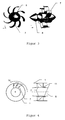
- Figure 3 shows an embodiment of the means 5 for the derivation in two views.
- the means 5 has tangentially curved blades 7 for attachment to the wall of the tube 1.
- FIG. 4 The operation of this embodiment is shown in Figure 4 in a front view (left partial image) and in a side view (right partial image).
- the fuel vapor 11 strikes the blades 7 in the form of a rotating flow. Due to the tangential bending of the blades 7, the fuel vapor 11 is converted into a flow along the surface of the means 5. The tangentially curved blades 7 thus cause a flow rectification.
- Figure 5 shows an embodiment of the nozzle 22 for the liquid fuel 13 and the nozzle 23 for the primary medium 14.
- the shape of which is determined by baffles 25 swirl generators 24 are arranged.
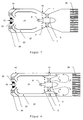
- FIG. 6 outlines the principle of returning hot gases to the evaporation zone by means of a recirculation line.
- the mixing chamber 21 has here not shown feeds for an oxidizing secondary medium. It Partial oxidation of the fuel vapor 11 occurs in a region 26 within the mixing chamber 21. This partial oxidation provides the energy for vaporization of heavy boiling components of the liquid fuel 13. Hot gases are returned from the rear of the mixing chamber through the recirculation line 27 to the evaporation zone ,
- FIG. 7 shows an exemplary embodiment of a recirculation line 27 within the evaporation chamber 21.
- the recirculation line 27 is arranged completely within the evaporation chamber 21.
- the tube 1 is followed by a reformer with a catalyst 28.
- Figure 8 shows an embodiment of the alternative arrangement in which the recirculation line 27 extends beyond the supply of the oxidant.
- the oxidant 12 is distributed over a, here trapezoidal drawn, air chamber on the feeders 2.
- a concrete embodiment is dimensioned for an autothermal diesel reformer, which is able to supply a fuel cell with an electric power of 50 kW with fuel gas. 13.5 kg of fuel are converted per hour.
- Aral Ultimate Diesel is used with an O 2 / C ratio of 0.47 and a H 2 O / C ratio of 1.90.
- As the primary medium 14 superheated steam having a temperature of 450 ° C is used.
- As the oxidizing secondary medium and as the oxidizing agent 12 air is used, which is supplied at ambient temperature.
- the mixing chamber has a length of 30 cm and a diameter of 12 cm.
- the evaporation chamber is 17.5 cm long.
- the recirculation line is 13 cm long, so it lies completely inside the evaporation chamber. It has a diameter of 9 cm.
Landscapes
- Chemical & Material Sciences (AREA)
- Chemical Kinetics & Catalysis (AREA)
- Organic Chemistry (AREA)
- Engineering & Computer Science (AREA)
- Combustion & Propulsion (AREA)
- Health & Medical Sciences (AREA)
- General Health & Medical Sciences (AREA)
- Inorganic Chemistry (AREA)
- Hydrogen, Water And Hydrids (AREA)
Abstract
Description
- Die Erfindung betrifft eine Vorrichtung zur Herstellung eines Kraftstoff-Oxidationsmittel-Gemischs.
- Brennstoffzellen zur Umwandlung chemischer Energie in elektrische Energie arbeiten am effektivsten, wenn ein wasserstoffhaltiges Gas als Brennstoff verwendet wird. Ein solches Gas lässt sich in einem Reformer aus kohlenwasserstoffhaltigen Brennstoffen gewinnen. Hierfür muss der Brennstoff verdampft und mit einem Oxidationsmittel vermischt werden.
- Aus der
deutschen Patentanmeldung 10 2004 055 425.0 ist eine Mischkammer bekannt, in der aus einem flüssigen Kraftstoff, wie Benzin oder Diesel, ein homogenes Kraftstoff-Luft-Gemisch für die Umsetzung zu einem wasserstoffreichen Gas in einem Reformer hergestellt werden kann. Der flüssige Kraftstoff wird in einer ersten Zone durch Kontakt mit einem heißen primären Medium, wie etwa Wasserdampf, verdampft. In einer zweiten Zone wird er mit dem Oxidationsmittel durchmischt. - Aus der
deutschen Patentanmeldung 10 2006 016 912.3 ist eine Mischkammer bekannt, in der der Kraftstoff vor der eigentlichen Durchmischung mit Hilfe eines oxidierenden sekundären Mediums teilweise oxidiert wird. Durch diese exotherme Reaktion werden auch schwer siedende Bestandteile des Kraftstoffs verdampft. - Nachteilig wird die Durchmischung des verdampften Kraftstoffs mit dem Oxidationsmittel bei größeren Mischkammern dieser Bauart tendenziell weniger homogen. Dadurch können Ablagerungen entstehen, die die Lebensdauer eines nachgeschalteten Reformers verringern.
- Aufgabe der Erfindung ist daher, eine Vorrichtung zur Verfügung zu stellen, in der auch größere Mengen an Kraftstoff homogen mit einem Oxidationsmittel durchmischt werden können.
- Diese Aufgabe wird erfindungsgemäß gelöst durch eine Vorrichtung gemäß Hauptanspruch. Weitere vorteilhafte Ausgestaltungen ergeben sich aus den darauf rückbezogenen Unteransprüchen.
- Im Rahmen der Erfindung wurde eine Vorrichtung zur Herstellung eines Kraftstoff-Oxidationsmittel-Gemischs für einen Reformer entwickelt. Diese Vorrichtung umfasst ein von einem Kraftstoffdampf in mindestens einer Strömungsrichtung durchströmbares Rohr mit mindestens einer Zuführung für ein Oxidationsmittel in seiner Wandung.
- Erfindungsgemäß ist im Bereich der Zuführung ein Mittel zur Ableitung der achsnahen Strömung des Kraftstoffdampfs in die äußeren Bereiche des Rohrs angeordnet.
- Unter dem Bereich der Zuführung im Sinne dieser Erfindung wird der Bereich verstanden, in dem sich das durch die Zuführung eingebrachte Oxidationsmittel ausbreitet.
- Es wurde erkannt, dass insbesondere für die Durchmischung des Kraftstoffs mit dem Oxidationsmittel bei größeren Querschnitten vorteilhafte Verwirbelungen des Oxidationsmittels den achsnahen Bereich des Rohrs häufig nachteilig vom Oxidationsmittel freihalten. Im achsnahen Bereich strömt somit Kraftstoff durch das Rohr, ohne mit dem Oxidationsmittel ausreichend durchmischt zu werden. Dies kann bei der Umsetzung des Kraftstoff-Oxidationsmittel-Gemischs in einem nachgeschalteten Reformer nachteilig zur Rußbildung führen. Das erfindungsgemäß vorgesehene Mittel zur Ableitung versperrt dem Kraftstoff den Weg durch den oxidationsmittelfreien achsnahen Bereich und lenkt ihn in die oxidationsmittelreichen äußeren Bereiche des Rohrs um. Dadurch entsteht ein deutlich homogeneres Kraftstoff-Oxidationsmittel-Gemisch als nach dem Stand der Technik.
- Diese Wirkung ist besonders ausgeprägt in einer vorteilhaften Ausgestaltung der Erfindung, in der die Stoffaustrittsrichtung der Zuführung axial oder tangential um bis zu 15 Grad von der radialen Richtung abweicht. Eine tangentiale Abweichung erzeugt rotierende Wirbel im zugeführten Oxidationsmittel, was die Durchmischung mit dem Kraftstoff verbessert. Andererseits neigen gerade diese rotierenden Wirbel dazu, den achsnahen Bereich des Rohrs vom Oxidationsmittel freizuhalten. Dieser nachteilige Effekt wird durch das erfindungsgemäß vorgesehene Mittel zur Ableitung unterbunden.
- Die Zuführung kann beispielsweise in mehreren Bohrungen in der Wandung des Rohrs bestehen. In einem konkreten Ausführungsbeispiel besteht die Zuführung aus 20 Bohrungen von je 2 mm Durchmesser bei einem Rohrdurchmesser von 70 mm.
- Die vorteilhafte Wirkung ist tendenziell bei Vorrichtungen mit größerem Rohrdurchmesser stärker ausgeprägt, da mit größerem Rohrdurchmesser auch der Durchmesser des achsnahen Bereichs wächst, der durch Verwirbelungen vom Oxidationsmittel freigehalten wird. Der nachteilige Effekt, der durch das erfindungsgemäße Mittel zur Ableitung unterbunden wird, wird in der Praxis bei Vorrichtungen für Reformer einer Größenordnung relevant, die genügend Brenngas für Brennstoffzellen mit einer elektrischen Leistung ab etwa 10 kW erzeugen. Im Ausführungsbeispiel wird eine Vorrichtung für einen Reformer beschrieben, der für die Brenngasversorgung von Brennstoffzellen mit einer elektrischen Leistung von 50 kW ausgelegt ist.
- Um den Strömungswiderstand durch das Mittel einerseits möglichst gering zu halten, andererseits aber die Durchmischung des Kraftstoffs mit dem Oxidationsmittel zu verbessern, sind besondere äußere Geometrien des Mittels besonders geeignet.
- Vorteilhaft nimmt der normal zur Strömungsrichtung gemessene Außendurchmesser des Mittels entlang der Strömungsrichtung ein lokales Maximum an. Insbesondere kann das Mittel wenigstens einen tropfenförmigen Teil umfassen. Es kann aber auch an seinem, in Strömungsrichtung gesehen, vorderen Ende einen größeren Außendurchmesser aufweisen als an seinem hinteren Ende und hier insbesondere wenigstens einen spindelförmigen Teil umfassen. Dies verbessert die Durchmischung des Kraftstoffs mit dem Oxidationsmittel und vermeidet Stauungen im Rohr.
- Vorteilhaft nimmt der normal zur Strömungsrichtung gemessene Außendurchmesser des Mittels entlang der Strömungsrichtung ein lokales Minimum an. Insbesondere kann dieses lokale Minimum, in Strömungsrichtung gesehen, vor dem Bereich der Zuführung angeordnet sein. Eine derartige wulstförmige Spitze des Mittels bewirkt, dass der kompakte Strom des Kraftstoffdampfs nicht erst im Bereich der Zuführung zu allen Seiten geleitet wird, sondern schon kurz vorher. Dies verbessert ebenfalls den Vermischungsprozess.
- In einer besonders vorteilhaften Ausgestaltung der Erfindung ist das Mittel ein längliches Mittel, welches sich sowohl vor als auch hinter den Bereich der Zuführung erstreckt.
- Unter einem länglichen Mittel wird ein Mittel verstanden, dessen größter Außendurchmesser senkrecht zur Strömungsrichtung des Kraftstoffdampfs geringer ist als seine Länge in Strömungsrichtung des Kraftstoffdampfs.
- Die längliche Ausgestaltung des Mittels bewirkt, dass der Kraftstoffdampf einen besonders langen Weg durch das oxidationsmittelreiche Gebiet zurücklegen muss. Er wird dadurch besonders gut mit dem Oxidationsmittel durchmischt.
- Ein größter Außendurchmesser des Mittels zwischen dem 0,3-fachen und dem 0,5-fachen des Rohrdurchmessers hat sich als vorteilhaft erwiesen. Ist der größte Außendurchmesser zu klein, versperrt das Mittel nicht den gesamten achsnahen, oxidationsmittelfreien Bereich. Ist er zu groß, staut sich der Kraftstoffdampf im Rohr, was die Durchmischung verschlechtert und gleichzeitig auch den Durchsatz beeinträchtigt. In einem konkreten Ausführungsbeispiel beträgt der größte Außendurchmesser des Mittels 3 cm, bei einem Rohrdurchmesser von 7 cm.
- Das Mittel kann aus jedem Werkstoff bestehen, der hochwärmefest ist und weder mit dem Oxidationsmittel noch mit dem Kraftstoff chemisch reagiert. Diese Anforderungen werden für übliche Kraftstoffe wie Benzin, Diesel, Kerosin und Heizöl insbesondere von Keramik und rostfreiem Stahl erfüllt.
- In einer besonders vorteilhaften Ausgestaltung der Erfindung ist das Mittel mit mindestens einem Verbindungselement an der Wandung des Rohrs befestigt. Dies behindert den Strom des Kraftstoff-Oxidationsmittel-Gemisches deutlich weniger als eine Befestigung des Mittels am nachgeschalteten Reformer.
- Hauptanforderung an das Verbindungselement ist, dass die Strömung des Kraftstoffdampfs möglichst wenig beeinträchtigt werden soll. Diese Anforderung wird am besten von einem Verbindungselement mit kreisförmigem Querschnitt erfüllt. Aber auch eine Schaufel als Verbindungselement behindert die Strömung nicht wesentlich, wenn sie gerade ist und ihre Kante auf die Strömung des Kraftstoffdampfs hin ausgerichtet ist.
- Unter einer Schaufel wird im Rahmen dieser Erfindung ein Blatt verstanden, dessen Dicke weniger als das 0,2-fache seiner Länge und seiner Breite beträgt. Der Werkstoff für die Schaufel kann aus den gleichen Werkstoffklassen gewählt werden, die auch für das Mittel selbst geeignet sind.
- Ein Verbindungselement mit kreisförmigem Querschnitt hat jedoch gegenüber einer geraden Schaufel den Vorteil, dass seine Wirkung auf die Strömung nicht von der genauen Strömungsrichtung abhängt.
- Bei rotierenden Strömungen wiederum ist es vorteilhaft, wenn die Schaufel gekrümmt und hier insbesondere tangential gekrümmt ist. Dies reduziert oder verhindert eine mögliche Ablösung der Strömung. Zugleich bewirkt diese Schaufelform eine noch bessere Durchmischung des Kraftstoffs mit dem Oxidationsmittel.
- Optional kann das Rohr im Bereich des Mittels eine Verengung aufweisen. Dies hält den oxidationsmittelfreien achsnahen Bereich von vornherein klein. Insoweit ergänzen sich die Wirkung der Verengung und die Wirkung des erfindungsgemäßen Mittels.
- In einer besonders vorteilhaften Ausgestaltung der Erfindung ist dem Rohr eine Verdampfungskammer vorgeschaltet. Diese weist dem Rohr axial gegenüber liegende Düsen für einen flüssigen Kraftstoff sowie für ein primäres Medium zur Verdampfung des Kraftstoffs auf. Eine derartige Verdampfungskammer liefert einen Kraftstoffdampf mit nur noch wenigen festen oder flüssigen Bestandteilen. Diese Bestandteile sind in der erfindungsgemäßen Vorrichtung nicht erwünscht, da sie sich insbesondere am Mittel zur Ablenkung anlagern können.
- Als primäres Medium ist prinzipiell jedes Medium geeignet, das eine höhere Temperatur aufweist als die Verdampfungstemperatur des Kraftstoffs und das mit dem Kraftstoff keine chemische Reaktion eingeht. Das für die Praxis relevanteste primäre Medium ist überhitzter Wasserdampf.
- Als flüssiger Kraftstoff wird üblicherweise ein raffiniertes Erdölprodukt wie Benzin, Diesel, Kerosin oder Heizöl verwendet.
- Vorteilhaft ist der Abstand zwischen den Düsen und dem Rohr mindestens dreimal so groß wie die in Strömungsrichtung des Kraftstoffdampfs gemessene Länge des Mittels. Dadurch wird sichergestellt, dass die Verdampfung des Kraftstoffs bereits abgeschlossen ist, wenn der Kraftstoffdampf auf das Mittel zur Ableitung trifft.
- Die rein physikalische Verdampfung des Kraftstoffs lässt sich durch konstruktive Maßnahmen an den Düsen der Verdampfungskammer weiter verbessern. Die Düse für den flüssigen Kraftstoff kann eine Dralldruckzerstäubungsdüse sein. Der Düse für das primäre Medium kann mindestens ein Drallerzeuger vorgeschaltet sein. Ein Drallerzeuger ist im Prinzip ein feststehendes Schaufelrad mit radialen, radial-tangentialen oder tangentialen Leitschaufeln, die je nach dem gewünschten Drallwinkel der Strömung ausgerichtet sind.
- Die Düse für das primäre Medium kann vorteilhaft die Düse für den flüssigen Kraftstoff umgeben und insbesondere mehrere Zuleitungen für das primäre Medium aufweisen. Das primäre Medium wird dann gleichmäßig verteilt und umströmt die Düse für den Kraftstoff. Die Strömung breitet sich in die positive axiale Richtung aus und vermischt sich mit dem Sprühbild des eingespritzten Kraftstoffs. Die Kombination der Düsen für das primäre Medium und für den Kraftstoff kann als Zweistoffdüse angesehen werden.
- Hinter diesen Maßnahmen steckt die gemeinsame Idee, dass eine starke Rotation der Strömungen von Kraftstoff und primärem Medium gegeneinander die Wechselwirkungsdauer erhöht und somit die Durchmischung verbessert.
- In einer besonders vorteilhaften Ausgestaltung der Erfindung weist die Verdampfungskammer zusätzliche Düsen für ein oxidierendes sekundäres Medium auf. Dieses sekundäre Medium kann insbesondere mit dem in das Rohr eingedüsten Oxidationsmittel identisch sein. Das sekundäre Medium oxidiert den Kraftstoff teilweise. Diese Flamme setzt Wärme frei, mit der auch schwer verdampfbare Anteile des Kraftstoffs verdampft werden können. Die festen und flüssigen Anteile im Kraftstoffdampf, die sich insbesondere am Mittel zur Ableitung oder auch in einem nachgeschalteten Reformer anlagern könnten, werden somit nochmals reduziert. Zwar kostet die teilweise Oxidation einen Teil der im Kraftstoff enthaltenen Energie, doch wird dies in der Regel dadurch aufgewogen, dass auch die bislang unverdampfbaren Kraftstoffanteile nunmehr verwertet werden, statt als Abfall abgeschieden werden zu müssen.
- Vorteilhaft ist mindestens eine Rezirkulationsleitung zur Rückführung von Gasen in den Bereich der Düsen für den Kraftstoff und für das primäre Medium vorgesehen. Diese Leitung führt mit Sauerstoff angereicherte heiße Gase zurück in den Bereich der Kraftstoffeinspritzung. Dadurch werden der Wärmetransport und der Stofftransport von Radikalen im Bereich der Flamme begünstigt.
- Die Rezirkulationsleitung kann vollständig innerhalb der Verdampfungskammer angeordnet sein. Dann werden Gase aus dem Bereich vor der Zuführung für das Oxidationsmittel zurückgeführt. Nur ein Teil des hier zugeführten Oxidationsmittels, etwa zwischen 10 und 30 Prozent, strömt wegen der Rückströmungen stromaufwärts in die Verdampfungskammer und somit in die Rezirkulationsleitung.
- Alternativ kann sich die Rezirkulationsleitung bis jenseits der Zuführung für das Oxidationsmittel erstrecken. Diese Ausgestaltung hat den Vorteil, dass die rückgeführten Gase heißer sind und einen höheren Sauerstoffgehalt aufweisen. Außerdem können der Kraftstoff und das sekundäre Medium länger miteinander wechselwirken als bei einer Rückführung innerhalb der Verdampfungskammer.
- Nachfolgend wird der Gegenstand der Erfindung anhand von Figuren näher erläutert, ohne dass der Gegenstand der Erfindung dadurch beschränkt wird. Es ist gezeigt:
- Figur 1:
- Ursache der ungenügenden Durchmischung nach dem Stand der Technik.
- Figur 2:
- Ausführungsbeispiel der erfindungsgemäßen Vorrichtung mit Verdampfungskammer, wobei das Mittel zur Ableitung eine wulstförmige Spitze aufweist.
- Figur 3:
- Ausführungsbeispiel des Mittels zur Ableitung mit tangential gebogenen Schaufeln.
- Figur 4:
- Prinzip der Strömungsgleichrichtung bei tangential gebogenen Schaufeln und rotierender Strömung.
- Figur 5:
- Ausführungsbeispiel der Düsen für den Kraftstoff und für das primäre Medium.
- Figur 6:
- Prinzip der Rückführung heißer Gase in die Verdampfungszone mit Hilfe einer Rezirkulationsleitung.
- Figur 7:
- Ausführungsbeispiel einer Rezirkulationsleitung innerhalb der Verdampfungskammer.
- Figur 8:
- Ausführungsbeispiel einer Rezirkulationsleitung, die sich bis jenseits der Zuführung für das Oxidationsmittel erstreckt.
- In Figur 1 ist die erfindungsgemäß erkannte Ursache der ungenügenden Durchmischung nach dem Stand der Technik skizziert. Die Vorrichtung umfasst ein Rohr 1, welches von einem Kraftstoffdampf 11 durchströmt werden kann. Das Rohr weist Zuführungen 2 für ein Oxidationsmittel 12 auf. Das Oxidationsmittel 12 bildet im Rohr 1 Verwirbelungen 3 aus. Diese halten den achsnahen Bereich 4 von Oxidationsmittel frei. Der Kraftstoffdampf 11 kann somit den Bereich 4 passieren, ohne mit dem Oxidationsmittel 12 durchmischt zu werden.
- Figur 2 zeigt ein Ausführungsbeispiel der erfindungsgemäßen Vorrichtung. Im achsnahen Bereich des Rohrs 1 befindet sich das erfindungsgemäße Mittel 5 zum Ableiten, welches eine wulstförmige Spitze 6 aufweist. Dadurch muss der Kraftstoffdampf 11 die Verwirbelungen 3 aus Oxidationsmittel passieren und sich dabei mit dem Oxidationsmittel durchmischen. Das Mittel 5 ist länglich ausgestaltet und erstreckt sich sowohl vor als auch hinter den Bereich, in dem das Oxidationsmittel 12 zugeführt wird. Der Kraftstoffdampf 11 wird von einer Mischkammer 21 bereitgestellt. Diese weist eine Düse 22 für einen flüssigen Kraftstoff sowie eine Düse 23 für ein primäres Medium auf, wobei die Düse 23 die Düse 22 umgibt.
- Figur 3 zeigt ein Ausführungsbeispiel des Mittels 5 zur Ableitung in zwei Ansichten. Das Mittel 5 weist tangential gebogene Schaufeln 7 zur Befestigung an der Wandung des Rohrs 1 auf.
- Die Wirkungsweise dieses Ausführungsbeispiels ist in Figur 4 in einer Vorderansicht (linkes Teilbild) und in einer Seitenansicht (rechtes Teilbild) dargestellt. Der Kraftstoffdampf 11 trifft in Form einer rotierenden Strömung auf die Schaufeln 7. Durch die tangentiale Biegung der Schaufeln 7 wird der Kraftstoffdampf 11 in eine Strömung entlang der Oberfläche des Mittels 5 überführt. Die tangential gebogenen Schaufeln 7 bewirken somit eine Strömungsgleichrichtung.
- Figur 5 zeigt ein Ausführungsbeispiel der Düse 22 für den flüssigen Kraftstoff 13 und der Düse 23 für das primäre Medium 14. In der Düse 23 für das primäre Medium, deren Form durch Leitbleche 25 bestimmt wird, sind Drallerzeuger 24 angeordnet.
- In Figur 6 ist das Prinzip der Rückführung heißer Gase in die Verdampfungszone mit Hilfe einer Rezirkulationsleitung skizziert. Die Mischkammer 21 weist hier nicht eingezeichnete Zuführungen für ein oxidierendes sekundäres Medium auf. Es kommt in einem Bereich 26 innerhalb der Mischkammer 21 zu einer partiellen Oxidation des Kraftstoffdampfs 11. Diese partielle Oxidation liefert die Energie für die Verdampfung schwer siedender Komponenten des flüssigen Kraftstoffs 13. Heiße Gase werden vom hinteren Teil der Mischkammer durch die Rezirkulationsleitung 27 in die Verdampfungszone zurückgeführt.
- Figur 7 zeigt ein Ausführungsbeispiel einer Rezirkulationsleitung 27 innerhalb der Verdampfungskammer 21. In diesem Ausführungsbeispiel ist die Rezirkulationsleitung 27 vollständig innerhalb der Verdampfungskammer 21 angeordnet. Dem Rohr 1 ist ein Reformer mit einem Katalysator 28 nachgeschaltet.
- Figur 8 zeigt ein Ausführungsbeispiel für die alternative Anordnung, bei der die Rezirkulationsleitung 27 sich bis jenseits der Zuführung für das Oxidationsmittel erstreckt. Das Oxidationsmittel 12 wird über eine, hier trapezförmig eingezeichnete, Luftkammer auf die Zuführungen 2 verteilt.
- Ein konkretes Ausführungsbeispiel ist für einen autothermen Dieselreformer dimensioniert, der eine Brennstoffzelle mit einer elektrischen Leistung von 50 kW mit Brenngas zu versorgen vermag. Pro Stunde werden 13,5 kg Kraftstoff umgesetzt. Es wird Aral Ultimate Diesel verwendet mit einem O2/C-Verhältnis von 0,47 und einem H2O/C-Verhältnis von 1,90. Als primäres Medium 14 wird überhitzter Wasserdampf mit einer Temperatur von 450 °C verwendet. Als oxidierendes sekundäres Medium sowie als Oxidationsmittel 12 wird Luft verwendet, die mit Umgebungstemperatur zugeführt wird. Die Mischkammer weist eine Länge von 30 cm und einen Durchmesser von 12 cm auf. Die Verdampfungskammer ist 17,5 cm lang. Die Rezirkulationsleitung ist 13 cm lang, liegt also vollständig innerhalb der Verdampfungskammer. Sie hat einen Durchmesser von 9 cm.
Claims (26)
- Vorrichtung zur Herstellung eines Kraftstoff-Oxidationsmittel-Gemischs für einen Reformer, umfassend ein von einem Kraftstoffdampf in mindestens einer Strömungsrichtung durchströmbares Rohr mit mindestens einer Zuführung für ein Oxidationsmittel in seiner Wandung, gekennzeichnet durch mindestens ein im Bereich der Zuführung angeordnetes Mittel zur Ableitung der achsnahen Strömung des Kraftstoffdampfs in die äußeren Bereiche des Rohrs.
- Vorrichtung nach Anspruch 1, gekennzeichnet durch eine Zuführung, deren Stoffaustrittsrichtung um bis zu 15 Grad von der radialen Richtung abweicht.
- Vorrichtung nach einem der Ansprüche 1 bis 2, gekennzeichnet durch ein Mittel, dessen normal zur Strömungsrichtung gemessener Außendurchmesser entlang der Strömungsrichtung ein lokales Maximum annimmt.
- Vorrichtung nach Anspruch 3, gekennzeichnet durch ein Mittel, das wenigstens einen tropfenförmigen Teil umfasst.
- Vorrichtung nach Anspruch 3, dadurch gekennzeichnet, dass das Mittel an seinem, in Strömungsrichtung gesehen, vorderen Ende einen größeren Außendurchmesser aufweist als an seinem hinteren Ende.
- Vorrichtung nach Anspruch 5, gekennzeichnet durch ein Mittel, das wenigstens einen spindelförmigen Teil umfasst.
- Vorrichtung nach einem der Ansprüche 1 bis 6, gekennzeichnet durch ein Mittel, dessen normal zur Strömungsrichtung gemessener Außendurchmesser entlang der Strömungsrichtung ein lokales Minimum annimmt.
- Vorrichtung nach Anspruch 7, dadurch gekennzeichnet, dass das lokale Minimum, in Strömungsrichtung gesehen, vor dem Bereich der Zuführung angeordnet ist.
- Vorrichtung nach einem der Ansprüche 1 bis 8, gekennzeichnet durch ein längliches Mittel, welches sich in Strömungsrichtung gesehen sowohl vor als auch hinter den Bereich der Zuführung erstreckt.
- Vorrichtung nach einem der Ansprüche 1 bis 9, gekennzeichnet durch einen größten Außendurchmesser des Mittels zwischen dem 0,3-fachen und dem 0,5-fachen des Rohrdurchmessers.
- Vorrichtung nach einem der Ansprüche 1 bis 10, gekennzeichnet durch ein Mittel aus Keramik oder rostfreiem Stahl.
- Vorrichtung nach einem der Ansprüche 1 bis 11, dadurch gekennzeichnet, dass das Mittel mit mindestens einem Verbindungselement an der Wandung des Rohrs befestigt ist.
- Vorrichtung nach Anspruch 12, gekennzeichnet durch ein Verbindungselement mit kreisförmigem Querschnitt.
- Vorrichtung nach Anspruch 12, gekennzeichnet durch eine Schaufel als Verbindungselement.
- Vorrichtung nach Anspruch 14, gekennzeichnet durch eine tangential gebogene Schaufel.
- Vorrichtung nach einem der Ansprüche 1 bis 15, dadurch gekennzeichnet, dass das Rohr im Bereich des Mittels eine Verengung aufweist.
- Vorrichtung nach einem der Ansprüche 1 bis 16, gekennzeichnet durch eine dem Rohr vorgeschaltete Verdampfungskammer mit dem Rohr axial gegenüber liegenden Düsen für einen flüssigen Kraftstoff sowie für ein primäres Medium zur Verdampfung des Kraftstoffs.
- Vorrichtung nach Anspruch 17, gekennzeichnet durch einen Abstand zwischen den Düsen und dem Rohr, der mindestens dreimal so groß ist wie die in Strömungsrichtung des Kraftstoffdampfs gemessene Länge des Mittels.
- Vorrichtung nach einem der Ansprüche 17 bis 18, gekennzeichnet durch eine Dralldruckzerstäubungsdüse für den flüssigen Kraftstoff.
- Vorrichtung nach einem der Ansprüche 17 bis 19, gekennzeichnet durch mindestens einen der Düse für das primäre Medium vorgeschalteten Drallerzeuger.
- Vorrichtung nach einem der Ansprüche 17 bis 20, gekennzeichnet durch eine die Düse für den flüssigen Kraftstoff umgebende Düse für das primäre Medium.
- Vorrichtung nach Anspruch 21, gekennzeichnet durch eine Düse für das primäre Medium mit mehreren Zuleitungen für das primäre Medium.
- Vorrichtung nach einem der Ansprüche 17 bis 22, gekennzeichnet durch eine Verdampfungskammer mit zusätzlichen Düsen für ein oxidierendes sekundäres Medium.
- Vorrichtung nach Anspruch 23, gekennzeichnet durch mindestens eine Rezirkulationsleitung zur Rückführung von Gasen in den Bereich der Düsen für den Kraftstoff und für das primäre Medium.
- Vorrichtung nach Anspruch 24, gekennzeichnet durch eine Rezirkulationsleitung, die vollständig innerhalb der Verdampfungskammer angeordnet ist.
- Vorrichtung nach Anspruch 24, gekennzeichnet durch eine Rezirkulationsleitung, die sich bis jenseits der Zuführung für das Oxidationsmittel erstreckt.
Applications Claiming Priority (1)
| Application Number | Priority Date | Filing Date | Title |
|---|---|---|---|
| DE102006024038A DE102006024038A1 (de) | 2006-05-23 | 2006-05-23 | Vorrichtung zur Herstellung eines Kraftstoff-Oxidationsmittel-Gemisches |
Publications (2)
| Publication Number | Publication Date |
|---|---|
| EP1859857A1 true EP1859857A1 (de) | 2007-11-28 |
| EP1859857B1 EP1859857B1 (de) | 2009-04-29 |
Family
ID=38370371
Family Applications (1)
| Application Number | Title | Priority Date | Filing Date |
|---|---|---|---|
| EP07008166A Active EP1859857B1 (de) | 2006-05-23 | 2007-04-21 | Vorrichtung zur Herstellung eines Kraftstoff-Oxidationsmittel-Gemischs |
Country Status (3)
| Country | Link |
|---|---|
| EP (1) | EP1859857B1 (de) |
| AT (1) | ATE429973T1 (de) |
| DE (2) | DE102006024038A1 (de) |
Families Citing this family (1)
| Publication number | Priority date | Publication date | Assignee | Title |
|---|---|---|---|---|
| DE102011119128A1 (de) | 2011-11-23 | 2013-05-23 | Thomas Magnete Gmbh | Einrichtung zum Dosieren und zur Vermischung von Fluidströmen |
Citations (4)
| Publication number | Priority date | Publication date | Assignee | Title |
|---|---|---|---|---|
| EP0303439A2 (de) * | 1987-08-14 | 1989-02-15 | DAVY McKEE CORPORATION | Gasmischer und -verteiler für einen Reaktor |
| US20030188486A1 (en) * | 2002-04-09 | 2003-10-09 | Nissan Motor Co., Ltd. | Fuel reformer |
| DE102004024957A1 (de) * | 2004-05-22 | 2005-12-22 | Uhde Gmbh | Verfahren und Vorrichtung zum Eindüsen von Sauerstoff in ein einen Synthesereaktor durchströmendes Reaktionsgas |
| DE102004055425A1 (de) * | 2004-11-17 | 2006-05-24 | Forschungszentrum Jülich GmbH | Mischkammer für einen Reformer sowie Verfahren zum Betreiben derselben |
Family Cites Families (13)
| Publication number | Priority date | Publication date | Assignee | Title |
|---|---|---|---|---|
| US3112988A (en) * | 1960-02-26 | 1963-12-03 | Sheil Oil Company | Mixing gases at supersonic velocity |
| US3920416A (en) * | 1973-12-26 | 1975-11-18 | California Inst Of Techn | Hydrogen-rich gas generator |
| DE2722226C2 (de) * | 1977-05-17 | 1982-08-19 | Herbert 5090 Leverkusen Kabisch | Vorrichtung zum Zerstäuben von Flüssigkeiten und zum Mischen von Gasen |
| DE3724344A1 (de) * | 1987-07-23 | 1989-02-02 | Huels Chemische Werke Ag | Mischduese zum vermischen zweier gasstroeme |
| DE4137573C2 (de) * | 1991-11-15 | 1998-01-15 | Motoren Werke Mannheim Ag | Venturi-Mischer zum Mischen von Gas und Luft, insbesondere für einen Verbrennungsmotor |
| DE10002004A1 (de) * | 2000-01-19 | 2001-08-09 | Bosch Gmbh Robert | Zerstäubungsvorrichtung |
| FR2804045B1 (fr) * | 2000-01-25 | 2002-03-29 | Air Liquide | Dispositif de melange d'un gaz secondaire dans un gaz principal |
| US6596424B2 (en) * | 2001-03-30 | 2003-07-22 | General Motors Corporation | Apparatus for mixing fuel and an oxidant |
| JP2002306938A (ja) * | 2001-04-11 | 2002-10-22 | Horiba Ltd | 流体混合装置 |
| US20030188475A1 (en) * | 2002-03-29 | 2003-10-09 | Shabbir Ahmed | Dynamic fuel processor with controlled declining temperatures |
| US7381382B2 (en) * | 2004-03-29 | 2008-06-03 | Massachusetts Institute Of Technology | Wide dynamic range multistage plasmatron reformer system |
| US20060021280A1 (en) * | 2004-07-30 | 2006-02-02 | Hamilton Daniel B | Reformer, and methods of making and using the same |
| DE102004041815A1 (de) * | 2004-08-30 | 2006-03-09 | Gvp Gesellschaft Zur Vermarktung Der Porenbrennertechnik Mbh | Verfahren und Vorrichtung zur Verdampfung von Flüssigbrennstoffen |
-
2006
- 2006-05-23 DE DE102006024038A patent/DE102006024038A1/de not_active Withdrawn
-
2007
- 2007-04-21 DE DE502007000658T patent/DE502007000658D1/de active Active
- 2007-04-21 AT AT07008166T patent/ATE429973T1/de active
- 2007-04-21 EP EP07008166A patent/EP1859857B1/de active Active
Patent Citations (4)
| Publication number | Priority date | Publication date | Assignee | Title |
|---|---|---|---|---|
| EP0303439A2 (de) * | 1987-08-14 | 1989-02-15 | DAVY McKEE CORPORATION | Gasmischer und -verteiler für einen Reaktor |
| US20030188486A1 (en) * | 2002-04-09 | 2003-10-09 | Nissan Motor Co., Ltd. | Fuel reformer |
| DE102004024957A1 (de) * | 2004-05-22 | 2005-12-22 | Uhde Gmbh | Verfahren und Vorrichtung zum Eindüsen von Sauerstoff in ein einen Synthesereaktor durchströmendes Reaktionsgas |
| DE102004055425A1 (de) * | 2004-11-17 | 2006-05-24 | Forschungszentrum Jülich GmbH | Mischkammer für einen Reformer sowie Verfahren zum Betreiben derselben |
Also Published As
| Publication number | Publication date |
|---|---|
| DE502007000658D1 (de) | 2009-06-10 |
| DE102006024038A1 (de) | 2007-11-29 |
| ATE429973T1 (de) | 2009-05-15 |
| EP1859857B1 (de) | 2009-04-29 |
Similar Documents
| Publication | Publication Date | Title |
|---|---|---|
| EP1206630B1 (de) | Vorrichtung zum einbringen eines zuschlagstoffes in ein abgas | |
| EP1990513B2 (de) | Vorrichtung zum Verteilen von fließfähigen Zusatzstoffen in Abgasanlagen | |
| DE102011111765B4 (de) | Mischereinrichtung | |
| EP2820260B1 (de) | Vorrichtung zur abgasreinigung | |
| DE102019210877A1 (de) | Mischer und Abgasnachbehandlungssystem | |
| EP1757778A1 (de) | Abgasführung einer Gasturbine sowie Verfahren zum Vermischen des Abgases der Gasturbine | |
| WO2007101427A1 (de) | Rundbrenner | |
| DE3614100A1 (de) | Brenner | |
| DE2431573A1 (de) | Brenneranordnung mit verminderter emission von die luft verunreinigenden stoffen | |
| DE102005063081A1 (de) | Einbauteil zur Montage in einem Abgasstrang einer Verbrennungskraftmaschine | |
| DE102014205158A1 (de) | Mischer für eine Abgasanlage | |
| EP2570178A1 (de) | Mischeinrichtung | |
| DE102014214093A1 (de) | Einrichtung zum Vermischen eines flüssigen Mediums mit einem Gasstrom | |
| EP0427033A2 (de) | Dampferzeuger | |
| EP3757364A1 (de) | Mischer für eine scr-abgasbehandlungsanlage | |
| DE2539888C2 (de) | Verfahren zur Vergasung von fein dispergierte Feststoffe enthaltendem Öl durch partielle Oxydation unter Flammenbildung und Einrichtung zu seiner Durchführung | |
| EP1446610A1 (de) | Verbrennungsverfahren, insbesondere für verfahren zur erzeugung von elektrischem strom und/oder von wärme | |
| CH680816A5 (de) | ||
| EP1859857B1 (de) | Vorrichtung zur Herstellung eines Kraftstoff-Oxidationsmittel-Gemischs | |
| DE102016014966B4 (de) | Abgasnachbehandlungseinrichtung für einen Kraftwagen | |
| EP3467383A1 (de) | Kesselanlage und verfahren zur erzeugung von wärme durch verbrennung wenigstens eines brennstoffes | |
| DE2345838A1 (de) | Brenner | |
| DE102022126147A1 (de) | Vorrichtung zur verdünnung der wasserstoffkonzentration in einem brennstoffzellen-abgassystem | |
| DD228338A1 (de) | Kohlenstaubbrenner | |
| DE102021111661A1 (de) | Strahlpumpe für ein Brennstoffzellensystem sowie Brennstoffzellensystem mit einer solchen Strahlpumpe |
Legal Events
| Date | Code | Title | Description |
|---|---|---|---|
| PUAI | Public reference made under article 153(3) epc to a published international application that has entered the european phase |
Free format text: ORIGINAL CODE: 0009012 |
|
| AK | Designated contracting states |
Kind code of ref document: A1 Designated state(s): AT BE BG CH CY CZ DE DK EE ES FI FR GB GR HU IE IS IT LI LT LU LV MC MT NL PL PT RO SE SI SK TR |
|
| AX | Request for extension of the european patent |
Extension state: AL BA HR MK YU |
|
| 17P | Request for examination filed |
Effective date: 20080405 |
|
| AKX | Designation fees paid |
Designated state(s): AT BE BG CH CY CZ DE DK EE ES FI FR GB GR HU IE IS IT LI LT LU LV MC MT NL PL PT RO SE SI SK TR |
|
| GRAP | Despatch of communication of intention to grant a patent |
Free format text: ORIGINAL CODE: EPIDOSNIGR1 |
|
| GRAS | Grant fee paid |
Free format text: ORIGINAL CODE: EPIDOSNIGR3 |
|
| GRAA | (expected) grant |
Free format text: ORIGINAL CODE: 0009210 |
|
| AK | Designated contracting states |
Kind code of ref document: B1 Designated state(s): AT BE BG CH CY CZ DE DK EE ES FI FR GB GR HU IE IS IT LI LT LU LV MC MT NL PL PT RO SE SI SK TR |
|
| REG | Reference to a national code |
Ref country code: GB Ref legal event code: FG4D Free format text: NOT ENGLISH |
|
| REG | Reference to a national code |
Ref country code: CH Ref legal event code: EP |
|
| REF | Corresponds to: |
Ref document number: 502007000658 Country of ref document: DE Date of ref document: 20090610 Kind code of ref document: P |
|
| REG | Reference to a national code |
Ref country code: DE Ref legal event code: R096 Ref document number: 502007000658 Country of ref document: DE Effective date: 20090610 Ref country code: IE Ref legal event code: FG4D |
|
| NLV1 | Nl: lapsed or annulled due to failure to fulfill the requirements of art. 29p and 29m of the patents act | ||
| PG25 | Lapsed in a contracting state [announced via postgrant information from national office to epo] |
Ref country code: FI Free format text: LAPSE BECAUSE OF FAILURE TO SUBMIT A TRANSLATION OF THE DESCRIPTION OR TO PAY THE FEE WITHIN THE PRESCRIBED TIME-LIMIT Effective date: 20090429 Ref country code: ES Free format text: LAPSE BECAUSE OF FAILURE TO SUBMIT A TRANSLATION OF THE DESCRIPTION OR TO PAY THE FEE WITHIN THE PRESCRIBED TIME-LIMIT Effective date: 20090809 Ref country code: LT Free format text: LAPSE BECAUSE OF FAILURE TO SUBMIT A TRANSLATION OF THE DESCRIPTION OR TO PAY THE FEE WITHIN THE PRESCRIBED TIME-LIMIT Effective date: 20090429 Ref country code: PT Free format text: LAPSE BECAUSE OF FAILURE TO SUBMIT A TRANSLATION OF THE DESCRIPTION OR TO PAY THE FEE WITHIN THE PRESCRIBED TIME-LIMIT Effective date: 20090829 |
|
| PG25 | Lapsed in a contracting state [announced via postgrant information from national office to epo] |
Ref country code: LV Free format text: LAPSE BECAUSE OF FAILURE TO SUBMIT A TRANSLATION OF THE DESCRIPTION OR TO PAY THE FEE WITHIN THE PRESCRIBED TIME-LIMIT Effective date: 20090429 Ref country code: SI Free format text: LAPSE BECAUSE OF FAILURE TO SUBMIT A TRANSLATION OF THE DESCRIPTION OR TO PAY THE FEE WITHIN THE PRESCRIBED TIME-LIMIT Effective date: 20090429 Ref country code: SE Free format text: LAPSE BECAUSE OF FAILURE TO SUBMIT A TRANSLATION OF THE DESCRIPTION OR TO PAY THE FEE WITHIN THE PRESCRIBED TIME-LIMIT Effective date: 20090729 Ref country code: NL Free format text: LAPSE BECAUSE OF FAILURE TO SUBMIT A TRANSLATION OF THE DESCRIPTION OR TO PAY THE FEE WITHIN THE PRESCRIBED TIME-LIMIT Effective date: 20090429 Ref country code: IS Free format text: LAPSE BECAUSE OF FAILURE TO SUBMIT A TRANSLATION OF THE DESCRIPTION OR TO PAY THE FEE WITHIN THE PRESCRIBED TIME-LIMIT Effective date: 20090829 Ref country code: PL Free format text: LAPSE BECAUSE OF FAILURE TO SUBMIT A TRANSLATION OF THE DESCRIPTION OR TO PAY THE FEE WITHIN THE PRESCRIBED TIME-LIMIT Effective date: 20090429 |
|
| PG25 | Lapsed in a contracting state [announced via postgrant information from national office to epo] |
Ref country code: DK Free format text: LAPSE BECAUSE OF FAILURE TO SUBMIT A TRANSLATION OF THE DESCRIPTION OR TO PAY THE FEE WITHIN THE PRESCRIBED TIME-LIMIT Effective date: 20090429 Ref country code: CZ Free format text: LAPSE BECAUSE OF FAILURE TO SUBMIT A TRANSLATION OF THE DESCRIPTION OR TO PAY THE FEE WITHIN THE PRESCRIBED TIME-LIMIT Effective date: 20090429 Ref country code: EE Free format text: LAPSE BECAUSE OF FAILURE TO SUBMIT A TRANSLATION OF THE DESCRIPTION OR TO PAY THE FEE WITHIN THE PRESCRIBED TIME-LIMIT Effective date: 20090429 Ref country code: RO Free format text: LAPSE BECAUSE OF FAILURE TO SUBMIT A TRANSLATION OF THE DESCRIPTION OR TO PAY THE FEE WITHIN THE PRESCRIBED TIME-LIMIT Effective date: 20090429 |
|
| PG25 | Lapsed in a contracting state [announced via postgrant information from national office to epo] |
Ref country code: SK Free format text: LAPSE BECAUSE OF FAILURE TO SUBMIT A TRANSLATION OF THE DESCRIPTION OR TO PAY THE FEE WITHIN THE PRESCRIBED TIME-LIMIT Effective date: 20090429 |
|
| PLBE | No opposition filed within time limit |
Free format text: ORIGINAL CODE: 0009261 |
|
| STAA | Information on the status of an ep patent application or granted ep patent |
Free format text: STATUS: NO OPPOSITION FILED WITHIN TIME LIMIT |
|
| PG25 | Lapsed in a contracting state [announced via postgrant information from national office to epo] |
Ref country code: BG Free format text: LAPSE BECAUSE OF FAILURE TO SUBMIT A TRANSLATION OF THE DESCRIPTION OR TO PAY THE FEE WITHIN THE PRESCRIBED TIME-LIMIT Effective date: 20090729 |
|
| 26N | No opposition filed |
Effective date: 20100201 |
|
| REG | Reference to a national code |
Ref country code: DE Ref legal event code: R097 Ref document number: 502007000658 Country of ref document: DE Effective date: 20100201 |
|
| PG25 | Lapsed in a contracting state [announced via postgrant information from national office to epo] |
Ref country code: GR Free format text: LAPSE BECAUSE OF FAILURE TO SUBMIT A TRANSLATION OF THE DESCRIPTION OR TO PAY THE FEE WITHIN THE PRESCRIBED TIME-LIMIT Effective date: 20090730 |
|
| PG25 | Lapsed in a contracting state [announced via postgrant information from national office to epo] |
Ref country code: IT Free format text: LAPSE BECAUSE OF FAILURE TO SUBMIT A TRANSLATION OF THE DESCRIPTION OR TO PAY THE FEE WITHIN THE PRESCRIBED TIME-LIMIT Effective date: 20090429 |
|
| PG25 | Lapsed in a contracting state [announced via postgrant information from national office to epo] |
Ref country code: MT Free format text: LAPSE BECAUSE OF FAILURE TO SUBMIT A TRANSLATION OF THE DESCRIPTION OR TO PAY THE FEE WITHIN THE PRESCRIBED TIME-LIMIT Effective date: 20090429 |
|
| PGFP | Annual fee paid to national office [announced via postgrant information from national office to epo] |
Ref country code: MC Payment date: 20120424 Year of fee payment: 6 Ref country code: LU Payment date: 20120424 Year of fee payment: 6 |
|
| PG25 | Lapsed in a contracting state [announced via postgrant information from national office to epo] |
Ref country code: CY Free format text: LAPSE BECAUSE OF FAILURE TO SUBMIT A TRANSLATION OF THE DESCRIPTION OR TO PAY THE FEE WITHIN THE PRESCRIBED TIME-LIMIT Effective date: 20090429 |
|
| PG25 | Lapsed in a contracting state [announced via postgrant information from national office to epo] |
Ref country code: HU Free format text: LAPSE BECAUSE OF FAILURE TO SUBMIT A TRANSLATION OF THE DESCRIPTION OR TO PAY THE FEE WITHIN THE PRESCRIBED TIME-LIMIT Effective date: 20091030 |
|
| PG25 | Lapsed in a contracting state [announced via postgrant information from national office to epo] |
Ref country code: TR Free format text: LAPSE BECAUSE OF FAILURE TO SUBMIT A TRANSLATION OF THE DESCRIPTION OR TO PAY THE FEE WITHIN THE PRESCRIBED TIME-LIMIT Effective date: 20090429 |
|
| PG25 | Lapsed in a contracting state [announced via postgrant information from national office to epo] |
Ref country code: MC Free format text: LAPSE BECAUSE OF NON-PAYMENT OF DUE FEES Effective date: 20130430 |
|
| REG | Reference to a national code |
Ref country code: FR Ref legal event code: PLFP Year of fee payment: 9 |
|
| PG25 | Lapsed in a contracting state [announced via postgrant information from national office to epo] |
Ref country code: LU Free format text: LAPSE BECAUSE OF NON-PAYMENT OF DUE FEES Effective date: 20130421 |
|
| REG | Reference to a national code |
Ref country code: FR Ref legal event code: PLFP Year of fee payment: 10 |
|
| REG | Reference to a national code |
Ref country code: FR Ref legal event code: PLFP Year of fee payment: 11 |
|
| REG | Reference to a national code |
Ref country code: FR Ref legal event code: PLFP Year of fee payment: 12 |
|
| P01 | Opt-out of the competence of the unified patent court (upc) registered |
Effective date: 20230517 |
|
| PGFP | Annual fee paid to national office [announced via postgrant information from national office to epo] |
Ref country code: IE Payment date: 20230425 Year of fee payment: 17 Ref country code: FR Payment date: 20230417 Year of fee payment: 17 Ref country code: CH Payment date: 20230502 Year of fee payment: 17 |
|
| PGFP | Annual fee paid to national office [announced via postgrant information from national office to epo] |
Ref country code: AT Payment date: 20230414 Year of fee payment: 17 |
|
| PGFP | Annual fee paid to national office [announced via postgrant information from national office to epo] |
Ref country code: BE Payment date: 20230417 Year of fee payment: 17 |
|
| PGFP | Annual fee paid to national office [announced via postgrant information from national office to epo] |
Ref country code: GB Payment date: 20230420 Year of fee payment: 17 |
|
| REG | Reference to a national code |
Ref country code: CH Ref legal event code: PL |
|
| REG | Reference to a national code |
Ref country code: AT Ref legal event code: MM01 Ref document number: 429973 Country of ref document: AT Kind code of ref document: T Effective date: 20240421 |
|
| GBPC | Gb: european patent ceased through non-payment of renewal fee |
Effective date: 20240421 |
|
| REG | Reference to a national code |
Ref country code: BE Ref legal event code: MM Effective date: 20240430 |
|
| PG25 | Lapsed in a contracting state [announced via postgrant information from national office to epo] |
Ref country code: BE Free format text: LAPSE BECAUSE OF NON-PAYMENT OF DUE FEES Effective date: 20240430 |
|
| PG25 | Lapsed in a contracting state [announced via postgrant information from national office to epo] |
Ref country code: GB Free format text: LAPSE BECAUSE OF NON-PAYMENT OF DUE FEES Effective date: 20240421 |
|
| PG25 | Lapsed in a contracting state [announced via postgrant information from national office to epo] |
Ref country code: FR Free format text: LAPSE BECAUSE OF NON-PAYMENT OF DUE FEES Effective date: 20240430 |
|
| PG25 | Lapsed in a contracting state [announced via postgrant information from national office to epo] |
Ref country code: AT Free format text: LAPSE BECAUSE OF NON-PAYMENT OF DUE FEES Effective date: 20240421 |
|
| PG25 | Lapsed in a contracting state [announced via postgrant information from national office to epo] |
Ref country code: GB Free format text: LAPSE BECAUSE OF NON-PAYMENT OF DUE FEES Effective date: 20240421 Ref country code: FR Free format text: LAPSE BECAUSE OF NON-PAYMENT OF DUE FEES Effective date: 20240430 Ref country code: BE Free format text: LAPSE BECAUSE OF NON-PAYMENT OF DUE FEES Effective date: 20240430 Ref country code: AT Free format text: LAPSE BECAUSE OF NON-PAYMENT OF DUE FEES Effective date: 20240421 Ref country code: CH Free format text: LAPSE BECAUSE OF NON-PAYMENT OF DUE FEES Effective date: 20240430 |
|
| PG25 | Lapsed in a contracting state [announced via postgrant information from national office to epo] |
Ref country code: IE Free format text: LAPSE BECAUSE OF NON-PAYMENT OF DUE FEES Effective date: 20240421 |
|
| PGFP | Annual fee paid to national office [announced via postgrant information from national office to epo] |
Ref country code: DE Payment date: 20250417 Year of fee payment: 19 |