EP1859518B1 - Adaptateur d'appareil - Google Patents
Adaptateur d'appareil Download PDFInfo
- Publication number
- EP1859518B1 EP1859518B1 EP06706798A EP06706798A EP1859518B1 EP 1859518 B1 EP1859518 B1 EP 1859518B1 EP 06706798 A EP06706798 A EP 06706798A EP 06706798 A EP06706798 A EP 06706798A EP 1859518 B1 EP1859518 B1 EP 1859518B1
- Authority
- EP
- European Patent Office
- Prior art keywords
- longitudinal
- base part
- device adapter
- rails
- longitudinal rails
- Prior art date
- Legal status (The legal status is an assumption and is not a legal conclusion. Google has not performed a legal analysis and makes no representation as to the accuracy of the status listed.)
- Active
Links
- 238000009434 installation Methods 0.000 claims description 7
- 230000008878 coupling Effects 0.000 claims description 6
- 238000010168 coupling process Methods 0.000 claims description 6
- 238000005859 coupling reaction Methods 0.000 claims description 6
- 230000000295 complement effect Effects 0.000 claims description 3
- 239000000725 suspension Substances 0.000 description 6
- 238000006073 displacement reaction Methods 0.000 description 5
- 238000010276 construction Methods 0.000 description 3
- 210000002105 tongue Anatomy 0.000 description 3
- 230000002349 favourable effect Effects 0.000 description 1
Images
Classifications
-
- H—ELECTRICITY
- H02—GENERATION; CONVERSION OR DISTRIBUTION OF ELECTRIC POWER
- H02B—BOARDS, SUBSTATIONS OR SWITCHING ARRANGEMENTS FOR THE SUPPLY OR DISTRIBUTION OF ELECTRIC POWER
- H02B1/00—Frameworks, boards, panels, desks, casings; Details of substations or switching arrangements
- H02B1/20—Bus-bar or other wiring layouts, e.g. in cubicles, in switchyards
- H02B1/21—Bus-bar arrangements for rack-mounted devices with withdrawable units
-
- H—ELECTRICITY
- H02—GENERATION; CONVERSION OR DISTRIBUTION OF ELECTRIC POWER
- H02B—BOARDS, SUBSTATIONS OR SWITCHING ARRANGEMENTS FOR THE SUPPLY OR DISTRIBUTION OF ELECTRIC POWER
- H02B1/00—Frameworks, boards, panels, desks, casings; Details of substations or switching arrangements
- H02B1/015—Boards, panels, desks; Parts thereof or accessories therefor
- H02B1/04—Mounting thereon of switches or of other devices in general, the switch or device having, or being without, casing
- H02B1/052—Mounting on rails
Definitions
- the invention relates to a device adapter with a base part, which is provided on its underside with rail receptacles for attaching and contacting on busbars and carries on its upper side with a releasably fastened connection means with two mounting devices arranged parallel spaced longitudinal bars for coupling electrical equipment or installation units.
- a device adapter of this type is in the DE 197 55 848 C2 specified.
- longitudinal strips are placed on the upper side of a housing-like base part along the longitudinal edges and locked to the base part by means of the longitudinal strips laterally projecting downwardly formed resilient locking tongues.
- the locking tongues are in the locked state in on the longitudinal side walls the base part incorporated recesses.
- the longitudinal strips have respective rows of holes directed perpendicularly to the upper side of the base part, via which devices, if appropriate, can be coupled with suitable fastening elements. To remove the longitudinal bars, the locking tongues must be released from their engagement position, which are associated with appropriate circumstances.
- a device adapter with laterally along the longitudinal edges mounted on a base part longitudinal strips shown.
- a longitudinally displaceable attachment part is mounted on the longitudinal strips, wherein the connection can also be made detachable, but in this regard no further details are made.
- the invention has for its object to provide a device adapter of the type mentioned above, which offers variable mounting options with a simple structure and ease of use.
- the connecting means are formed as formed on the underside of the longitudinal strips, protruding, hook-like suspension elements in perpendicular thereto adapted receiving openings on the upper side of the base vertically insertable and by a displacement in the longitudinal direction in the area behind the receiving openings on their the upper side remote side are suspended, and that for releasing the hinged position of the longitudinal strips a releasable locking element is present.
- the longitudinal strips can be easily mounted on the top of the base part and also solved.
- the locking element as a removable pluggable and / or lockable pin, which is perpendicular from the top through an adapted passage opening of the relevant longitudinal bar in a customized, aligned in the mounted position Arretierelementsuit, or that Locking element is formed as formed on the longitudinal bar or the base part locking element which engages in a locking counter-element on the base part or the longitudinal bar.
- the two longitudinal strips attached or to be attached to the lateral edge regions of the base part are connected to one another via two detachable transverse strips, a unit of the two longitudinal strips and the transverse strips can be preassembled and easily mounted on the base part.
- transverse strips have the corresponding cross-section as the longitudinal strips and have at the mutual end portions on their underside vertically downwardly projecting retaining legs.
- a simple, stable attachment to the support means results from the fact that the support means is provided on its the front side of the base side facing side with a support structure which is brought in the attached state of the longitudinal strips in a respective complementary thereto support means receiving.
- An advantageous embodiment for the handling of the device adapter further consists in that a longitudinal bar in the attached state ends with its one end by a certain distance in front of the relevant end face of the base part and that arranged in the released portion of the base part a handle for actuating a bolt of the device adapter is.
- a simple coupling of devices or installation units is facilitated by the fact that on the top of the two parallel spaced longitudinal strips a parallel distance bridging attachment for coupling devices or installation units in the longitudinal direction along the longitudinal strips slidably engaged and fixed by means of fasteners in a selectable position on the long sides is.
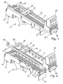
- Fig. 1 shows a device adapter 1 with a base part 10 and a built-up device 20 with two longitudinally spaced on the longitudinal edges of the base member 10 arranged longitudinal strips 21, 24 and connecting them cross bars 25, 26.
- On the longitudinal strips 21, 24 is for easy attachment of devices or Installation units a the distance between the two longitudinal strips bridging attachment part 30 in the form of a DIN rail with its base on the top of the longitudinal strips 21, 24 placed and fixed thereto by means of fastening means 32 in the form of screws, as well as the Fig. 2 . 3 . 5 and 6 demonstrate.
- the attachment 30 Before the attachment 30 is fixed in its end-valid position, it is fixed on the longitudinal strips by means of downwardly projecting latching retaining elements 31 to this and can be moved along the longitudinal strips 21, 24 in the desired position become.
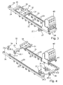
- connection unit 40 is attached to a section projecting beyond the one end side of the essentially cuboid base part 10 by means of screws which are perpendicular to the upper side of the building device 20 or the device adapter 1 into the longitudinal strips 21, 24 engage inserted holes.
- the holes form in the longitudinal strips 21, 24 a respective row of holes with a specific grid.
- the longitudinal strips 21 are introduced with the suspension elements 22 perpendicular to the top of the base member 10 in the receiving openings 13 and then moved in the longitudinal direction of the base member 10, so that the likewise in the direction of displacement projecting hook parts are brought into their holding position.
- this is fixed by means of a locking element 28 on a longitudinal bar 24 or alternatively both longitudinal strips 21, 24 by means of a pin-like locking element 28 against displacement, wherein the locking element 28 with a shaft part in one on the top of the base part 10 incorporated at the appropriate place locking element 19 preferably detent engages.
- the relevant longitudinal bar 24 is this, as in particular from Fig.
- the longitudinal strips 21, 24 are provided on their mutually facing sides with aligned transverse pins 24.1, 24.2 for connecting to the transverse strips 25, 26.
- the transverse strips 25, 26, which advantageously have the same cross-section as the longitudinal strips 21, 24, provided at least in their end portions with the cross-section of the transverse pins 24.1, 24.2 in cross section adapted cavities 25.2, 26.2.
- the mounting device 20 can be pre-assembled before installation on the base part 10 by means of simple plug-in mounting, whereby the attachment of the mounting device 20 on the base part 10 can be easily made.
- the transverse strips 25, 26 are provided on their underside with retaining legs 25.1, 26.1 formed thereon, which may additionally be equipped with locking elements for fixing to the base part 10 and interact with counter-holding elements of the base part 10.
- a triangular-shaped, rectangular support means 27 is arranged on its side the end wall 18 facing side is provided with a holding structure 27.1 in the form of an integrally formed, in cross-section T-shaped or dovetailed rib, which is arranged in a arranged on the end face of the base part 10 complementary Holding means 15 engages in the form of an undercut T-groove.
- the support means 27 is inserted with its support structure 27.1 in the support means receptacle 15 and then applied the mounting device 20 and hooked.
- the terminal unit 40 can be connected by the longitudinal strips 21, 24 with fastening screws also with the support means 27.
- FIG. 1 and 2 further show, three rail receivers 11 are formed on the underside of the base part 10, in which transversely to the base member 10 and the device adapter 1 extending busbars can be added.
- the rail receivers are separated from one another by means of boundary walls 17 running transversely to the base part 10.
- For contacting with the busbars 11 Jardinierabête 60 for-the electrical contacting of the busbars are arranged on the underside of the base part 10 in the rail receptacles.
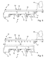
- hook parts 55 can be fixed for attachment of the device adapter 1 to the busbars 55, such as Fig. 5 shows.
- To lock the applied on the busbar device adapter 1 is in at least one rail mount 11, such as Fig.
- the base part 10 shows a stepped, in the base part 10 against a spring force retractable locking element 70 is provided.
- the locking element 70 can be unlocked by means of a on the upper side of the base member 10 at one end portion projecting handle 50, so that the device adapter 1 can be removed from the busbars.
- the base part 10 also has at least one hook-shaped retaining means 12 on the underside of its one end section.
- the handle 50 for the locking element 70 which is a longitudinal bar 21 shortened at the respective end portion, so that the handle 50 can be easily arranged and operated in this area.
Landscapes
- Engineering & Computer Science (AREA)
- Power Engineering (AREA)
- Mutual Connection Of Rods And Tubes (AREA)
- Connection Of Plates (AREA)
- Installation Of Bus-Bars (AREA)
- Connections Arranged To Contact A Plurality Of Conductors (AREA)
- Details Of Connecting Devices For Male And Female Coupling (AREA)
- Conveying And Assembling Of Building Elements In Situ (AREA)
Claims (10)
- Adaptateur d'appareil comprenant une partie de base (10), qui est dotée sur son côté inférieur de logements de rail (11) pour le placement et la mise en contact sur des rails de barres conductrices de courant et porte sur son côté supérieur un dispositif de montage (20), fixé de façon amovible avec des moyens de liaison, avec deux baguettes longitudinales (21, 24) espacées parallèlement l'une de l'autre, pour le couplage d'appareils électriques ou d'unités d'installation (40),
les moyens de liaison étant conçus sous forme d'éléments d'accrochage (22) formés sur le côté inférieur des baguettes longitudinales (21, 24), saillants, en forme de crochet, qui peuvent être introduits verticalement dans des ouvertures de logement (13) adaptées dessus sur le côté supérieur de la partie de base (10), caractérisés en ce que les baguettes longitudinales peuvent être accrochées par un coulissement dans le sens longitudinal dans la zone située derrière les ouvertures de logement (22) sur leur côté opposé au côté supérieur, et
en ce qu'un élément d'arrêt (28) pouvant être libéré est présent pour arrêter la position accrochée des baguettes longitudinales (21, 24) - Adaptateur d'appareil selon la revendication 1,
caractérisé
en ce que les éléments d'accrochage (22) présentent des parties d'extrémité dépassant dans le sens de coulissement ou
en ce que les éléments d'accrochage (22) présentent des tronçons d'extrémité élargis et les ouvertures de logement (22) sont conçues sous forme d'ouvertures orientées dans le sens de la longueur et en forme de trou de serrure. - Adaptateur d'appareil selon la revendication 1 ou 2,
caractérisé
en ce que l'élément d'arrêt (28) se présente sous forme d'une broche amovible, pouvant être enfichée et/ou encliquetée, qui peut être insérée verticalement depuis le côté supérieur à travers une ouverture d'introduction (24.3) adaptée de la baguette longitudinale (24) concernée dans un logement d'élément d'arrêt (19) adapté et aligné dans la position accrochée, ou
en ce que l'élément d'arrêt est conçu sous forme d'élément d'encliquetage formé sur la baguette longitudinale (24) ou la partie de base (10), lequel élément s'engage dans un contre-élément d'arrêt sur la partie de base (10) ou la baguette longitudinale (24). - Adaptateur d'appareil selon l'une des revendications précédentes,
caractérisé
en ce que les deux baguettes longitudinales (21, 24) placées ou à placer sur les zones de bord latérales de la partie de base (10) sont reliées les unes aux autres au moyen de deux baguettes transversales (25, 26) amovibles. - Adaptateur d'appareil selon la revendication 4,
caractérisé
en ce que les baguettes transversales (25, 26) présentent une section appropriée comme les baguettes longitudinales (21, 24) et présentent sur les tronçons d'extrémité situés des deux côtés sur leur côté inférieur des branches de retenue (25.1, 26.1) dépassant verticalement vers le bas. - Adaptateur d'appareil selon la revendication 4 ou 5
caractérisé
en ce que des tenons transversaux (24.1, 24.2) orientés dans le sens contraire sont formés sur les côtés intérieurs tournés les unes vers les autres des baguettes longitudinales (21, 24) dans une position adaptée les unes aux autres et
en ce que les baguettes transversales (25, 26) présentent au moins dans leurs tronçons d'extrémité des cavités agencées dans leur direction longitudinale, ouvertes sur l'extrémité et adaptées dans leur section à la section des tenons transversaux (24.1, 24.2) pour l'enfichage des tenons transversaux (24.1, 24.2) - Adaptateur d'appareil selon l'une des revendications précédentes,
caractérisé
en ce que les deux baguettes longitudinales (21, 24) dépassent dans l'état mis en place avec des tronçons d'extrémité de la partie de base (10) sur un côté avant et en ce qu'un moyen de soutien (27) est placé dans la plage d'angle entre le côté avant de la partie de base (10) et le côté inférieur de la baguette longitudinale. - Adaptateur d'appareil selon la revendication 7,
caractérisé
en ce que le moyen de soutien (27) est doté sur son côté, tourné vers le côté avant de la partie de base (10), d'une structure de retenue (27.1), qui est mise en place dans un logement de moyen de soutien (15) respectif, complémentaire par rapport à elle, dans l'état installé des baguettes longitudinales (21, 24). - Adaptateur d'appareil selon l'une des revendications précédentes,
caractérisé
en ce qu'une baguette longitudinale (21) se termine dans l'état installé par l'une de ses extrémités à une distance définie devant le côté avant concerné de la partie de base (10) et
en ce qu'une manette (50) destinée à l'actionnement d'un verrou de l'adaptateur d'appareil est disposée dans la partie libérée de la partie de base (10). - Adaptateur d'appareil selon l'une des revendications précédentes,
caractérisé
en ce qu'une partie rapportée (30) surmontant l'espacement parallèle est encliquetée de façon coulissante sur le côté supérieur des baguettes longitudinales (21, 24) espacées en parallèle pour l'accouplement d'appareils ou d'unités d'installation dans le sens longitudinal le long des baguettes longitudinales (21, 24) et peut être fixée à l'aide de moyens de fixation (32) dans une position pouvant être choisie sur les côtés longitudinaux (21, 24).
Priority Applications (1)
| Application Number | Priority Date | Filing Date | Title |
|---|---|---|---|
| PL06706798T PL1859518T3 (pl) | 2005-03-04 | 2006-02-10 | Adapter urządzeń |
Applications Claiming Priority (2)
| Application Number | Priority Date | Filing Date | Title |
|---|---|---|---|
| DE102005009993A DE102005009993B3 (de) | 2005-03-04 | 2005-03-04 | Geräteadapter |
| PCT/EP2006/001167 WO2006094595A1 (fr) | 2005-03-04 | 2006-02-10 | Adaptateur d'appareil |
Publications (2)
| Publication Number | Publication Date |
|---|---|
| EP1859518A1 EP1859518A1 (fr) | 2007-11-28 |
| EP1859518B1 true EP1859518B1 (fr) | 2012-09-19 |
Family
ID=36143449
Family Applications (1)
| Application Number | Title | Priority Date | Filing Date |
|---|---|---|---|
| EP06706798A Active EP1859518B1 (fr) | 2005-03-04 | 2006-02-10 | Adaptateur d'appareil |
Country Status (7)
| Country | Link |
|---|---|
| US (1) | US7520776B2 (fr) |
| EP (1) | EP1859518B1 (fr) |
| JP (1) | JP2008509511A (fr) |
| CN (1) | CN101133533B (fr) |
| DE (1) | DE102005009993B3 (fr) |
| PL (1) | PL1859518T3 (fr) |
| WO (1) | WO2006094595A1 (fr) |
Families Citing this family (12)
| Publication number | Priority date | Publication date | Assignee | Title |
|---|---|---|---|---|
| DE202006006469U1 (de) * | 2005-10-20 | 2007-03-01 | Weidmüller Interface GmbH & Co. KG | Vormontierte elektrische Installationseinheit |
| DE102006042947A1 (de) * | 2006-09-13 | 2008-03-27 | Siemens Ag | Hutschienenträger und Hutschiene mit zwei Hutschienenträgern |
| DE102008014177A1 (de) * | 2008-03-14 | 2009-09-17 | Phoenix Contact Gmbh & Co. Kg | Reihenklemme und Reihenklemmblock |
| US8547684B2 (en) * | 2009-12-17 | 2013-10-01 | Schneider Electric USA, Inc. | Panelboard having a parallel feeder bars distribution |
| DE102011052381B4 (de) * | 2011-08-03 | 2013-04-18 | Rittal Gmbh & Co. Kg | Sammelschienenadapter mit einer Tragschiene für die Befestigung eines Schaltgeräts |
| DE102012014980A1 (de) * | 2012-07-25 | 2014-05-15 | Friedrich Lütze GmbH | Montagesystem für die Anordnung von beispielsweise elektrischen Einrichtungen insbesondere in Schaltschränken |
| US9397462B2 (en) * | 2012-12-28 | 2016-07-19 | General Electric Company | Rail mounting system and detaching method |
| DE202014100115U1 (de) * | 2013-01-15 | 2014-04-16 | Weidmüller Interface GmbH & Co. KG | Anordnung mit einem Modul und einer Elektronikanordnung |
| DE102013110788B4 (de) * | 2013-09-30 | 2015-12-03 | Klaus Bruchmann Gmbh | Sammelschienen-Adapter |
| DE102013111857B4 (de) * | 2013-10-28 | 2015-05-13 | Klaus Bruchmann Gmbh | Gesicherter Sammelschienenadapter |
| DE102014105955B4 (de) * | 2014-04-29 | 2015-12-24 | Phoenix Contact Gmbh & Co. Kg | Montageanordnung für Reihenklemmen |
| DE202016100307U1 (de) * | 2016-01-22 | 2017-04-26 | Weidmüller Interface GmbH & Co. KG | Reihenbausteinanordnung mit einem Energiebussystem |
Family Cites Families (6)
| Publication number | Priority date | Publication date | Assignee | Title |
|---|---|---|---|---|
| US4387872A (en) * | 1981-01-17 | 1983-06-14 | Packard Industries, Inc. | Latch for a tab and slot mounting bracket |
| US4916574A (en) * | 1989-06-06 | 1990-04-10 | Siemens Energy & Automation, Inc. | Panelboard bus bar arrangement |
| US5178555A (en) * | 1991-10-02 | 1993-01-12 | Amp Incorporated | Installation of junction boxes along a raceway |
| DE19755848C2 (de) * | 1997-12-15 | 2002-07-18 | Rittal Gmbh & Co Kg | Multifunktionsadapter für eine Anzahl von Stromsammelschienen eines Sammelschienensystems |
| DE29811379U1 (de) * | 1998-06-25 | 1998-09-10 | Loh Kg Rittal Werk | Geräteadapter mit verstellbarem und arretierbarem Geräteträger |
| DE10005818A1 (de) * | 2000-02-10 | 2001-08-16 | Moeller Gmbh | Vorrichtung zur Befestigung von Schaltgeräten auf Tragschienen |
-
2005
- 2005-03-04 DE DE102005009993A patent/DE102005009993B3/de active Active
-
2006
- 2006-02-10 PL PL06706798T patent/PL1859518T3/pl unknown
- 2006-02-10 JP JP2007524356A patent/JP2008509511A/ja active Pending
- 2006-02-10 CN CN2006800070794A patent/CN101133533B/zh active Active
- 2006-02-10 EP EP06706798A patent/EP1859518B1/fr active Active
- 2006-02-10 WO PCT/EP2006/001167 patent/WO2006094595A1/fr not_active Application Discontinuation
- 2006-02-10 US US11/667,809 patent/US7520776B2/en active Active
Also Published As
| Publication number | Publication date |
|---|---|
| CN101133533B (zh) | 2010-06-23 |
| DE102005009993B3 (de) | 2006-06-14 |
| US7520776B2 (en) | 2009-04-21 |
| WO2006094595A1 (fr) | 2006-09-14 |
| PL1859518T3 (pl) | 2013-01-31 |
| CN101133533A (zh) | 2008-02-27 |
| US20080002338A1 (en) | 2008-01-03 |
| EP1859518A1 (fr) | 2007-11-28 |
| JP2008509511A (ja) | 2008-03-27 |
Similar Documents
| Publication | Publication Date | Title |
|---|---|---|
| EP1859518B1 (fr) | Adaptateur d'appareil | |
| DE3643559C2 (de) | In einem Brüstungskanal befestigbare Einbaudose | |
| EP1431765A2 (fr) | Dispositif de couplage d'un compteur d'électricité à une plate-forme de support | |
| EP2171817A1 (fr) | Dispositif pour installer et fixer des unités électriques, en particulier dans une armoire de distribution, ainsi que système de montage comportant un tel dispositif | |
| EP3461963B1 (fr) | Système porteur et système d'éléments de connexion permettant la connexion des porteurs | |
| EP1002166A1 (fr) | Cloison, notamment pour stands d'expositions | |
| DE4438921C1 (de) | Vorrichtung zum Montieren schwerer elektrischer Steckverbindereinsätze auf Tragschienen | |
| DE2810764C2 (fr) | ||
| EP0507893A1 (fr) | Dispositif pour la fixation rapide d'appareils electriques a encastrer en serie. | |
| DE202017104115U1 (de) | Einfassung zum Aufnehmen von Erd- und/oder Kompostmaterial | |
| EP2863497B1 (fr) | Armoire ou boîte de distribution de l'installation électrique de bâtiments | |
| DE3300729C2 (fr) | ||
| EP0933853B1 (fr) | Support de reception d'un bloc-prise pour plinthe de distribution | |
| DE102016123889A1 (de) | Verbindungsanordnung zum Verbinden eines Pfostens mit einem Rahmenprofil eines Fensters oder einer Türe aus Kunststoff | |
| EP1463170A2 (fr) | Armoire de distribution ou pour compteur électrique | |
| DE1905735A1 (de) | Abhaengbare Deckenkonstruktion | |
| EP2657401B1 (fr) | Plaque de montage | |
| DE102019104723B4 (de) | Schaltschrankanordnung mit einem Schaltschrank und mindestens einer Steckdosenleiste | |
| WO2000051465A1 (fr) | Dispositif permettant de fixer des rayons d'etagere | |
| DE10135662A1 (de) | Gerätebecherrahmen für Unterfluranwendungen | |
| DE102008010205A1 (de) | Profilschiene | |
| DE60319315T2 (de) | Verriegelungselement für einen Gitterrost auf einer Entwässerungsrinne und Werkzeug zum Entfernen desselben | |
| EP2372852A2 (fr) | Armoire de distribution ou pour compteur électrique | |
| DE2439362C2 (de) | Traggerippe für eine Unterdecke | |
| DE2609448C3 (de) | Türanschlagleiste für einen Kabelverteilerschrank aus Kunststoff |
Legal Events
| Date | Code | Title | Description |
|---|---|---|---|
| PUAI | Public reference made under article 153(3) epc to a published international application that has entered the european phase |
Free format text: ORIGINAL CODE: 0009012 |
|
| 17P | Request for examination filed |
Effective date: 20071004 |
|
| AK | Designated contracting states |
Kind code of ref document: A1 Designated state(s): AT DE FR PL |
|
| DAX | Request for extension of the european patent (deleted) | ||
| RBV | Designated contracting states (corrected) |
Designated state(s): AT DE FR PL |
|
| GRAP | Despatch of communication of intention to grant a patent |
Free format text: ORIGINAL CODE: EPIDOSNIGR1 |
|
| GRAS | Grant fee paid |
Free format text: ORIGINAL CODE: EPIDOSNIGR3 |
|
| GRAA | (expected) grant |
Free format text: ORIGINAL CODE: 0009210 |
|
| AK | Designated contracting states |
Kind code of ref document: B1 Designated state(s): AT DE FR PL |
|
| REG | Reference to a national code |
Ref country code: AT Ref legal event code: REF Ref document number: 576427 Country of ref document: AT Kind code of ref document: T Effective date: 20121015 |
|
| REG | Reference to a national code |
Ref country code: DE Ref legal event code: R096 Ref document number: 502006011994 Country of ref document: DE Effective date: 20121115 |
|
| REG | Reference to a national code |
Ref country code: PL Ref legal event code: T3 |
|
| PLBE | No opposition filed within time limit |
Free format text: ORIGINAL CODE: 0009261 |
|
| STAA | Information on the status of an ep patent application or granted ep patent |
Free format text: STATUS: NO OPPOSITION FILED WITHIN TIME LIMIT |
|
| 26N | No opposition filed |
Effective date: 20130620 |
|
| REG | Reference to a national code |
Ref country code: DE Ref legal event code: R097 Ref document number: 502006011994 Country of ref document: DE Effective date: 20130620 |
|
| REG | Reference to a national code |
Ref country code: FR Ref legal event code: PLFP Year of fee payment: 11 |
|
| REG | Reference to a national code |
Ref country code: FR Ref legal event code: PLFP Year of fee payment: 12 |
|
| REG | Reference to a national code |
Ref country code: FR Ref legal event code: PLFP Year of fee payment: 13 |
|
| PGFP | Annual fee paid to national office [announced via postgrant information from national office to epo] |
Ref country code: FR Payment date: 20230217 Year of fee payment: 18 |
|
| PGFP | Annual fee paid to national office [announced via postgrant information from national office to epo] |
Ref country code: PL Payment date: 20230203 Year of fee payment: 18 |
|
| P01 | Opt-out of the competence of the unified patent court (upc) registered |
Effective date: 20230525 |
|
| PGFP | Annual fee paid to national office [announced via postgrant information from national office to epo] |
Ref country code: AT Payment date: 20240216 Year of fee payment: 19 |
|
| PGFP | Annual fee paid to national office [announced via postgrant information from national office to epo] |
Ref country code: DE Payment date: 20240216 Year of fee payment: 19 |