EP1859518B1 - Device adapter - Google Patents
Device adapter Download PDFInfo
- Publication number
- EP1859518B1 EP1859518B1 EP06706798A EP06706798A EP1859518B1 EP 1859518 B1 EP1859518 B1 EP 1859518B1 EP 06706798 A EP06706798 A EP 06706798A EP 06706798 A EP06706798 A EP 06706798A EP 1859518 B1 EP1859518 B1 EP 1859518B1
- Authority
- EP
- European Patent Office
- Prior art keywords
- longitudinal
- base part
- device adapter
- rails
- longitudinal rails
- Prior art date
- Legal status (The legal status is an assumption and is not a legal conclusion. Google has not performed a legal analysis and makes no representation as to the accuracy of the status listed.)
- Active
Links
- 238000009434 installation Methods 0.000 claims description 7
- 230000008878 coupling Effects 0.000 claims description 6
- 238000010168 coupling process Methods 0.000 claims description 6
- 238000005859 coupling reaction Methods 0.000 claims description 6
- 230000000295 complement effect Effects 0.000 claims description 3
- 239000000725 suspension Substances 0.000 description 6
- 238000006073 displacement reaction Methods 0.000 description 5
- 238000010276 construction Methods 0.000 description 3
- 210000002105 tongue Anatomy 0.000 description 3
- 230000002349 favourable effect Effects 0.000 description 1
Images
Classifications
-
- H—ELECTRICITY
- H02—GENERATION; CONVERSION OR DISTRIBUTION OF ELECTRIC POWER
- H02B—BOARDS, SUBSTATIONS OR SWITCHING ARRANGEMENTS FOR THE SUPPLY OR DISTRIBUTION OF ELECTRIC POWER
- H02B1/00—Frameworks, boards, panels, desks, casings; Details of substations or switching arrangements
- H02B1/20—Bus-bar or other wiring layouts, e.g. in cubicles, in switchyards
- H02B1/21—Bus-bar arrangements for rack-mounted devices with withdrawable units
-
- H—ELECTRICITY
- H02—GENERATION; CONVERSION OR DISTRIBUTION OF ELECTRIC POWER
- H02B—BOARDS, SUBSTATIONS OR SWITCHING ARRANGEMENTS FOR THE SUPPLY OR DISTRIBUTION OF ELECTRIC POWER
- H02B1/00—Frameworks, boards, panels, desks, casings; Details of substations or switching arrangements
- H02B1/015—Boards, panels, desks; Parts thereof or accessories therefor
- H02B1/04—Mounting thereon of switches or of other devices in general, the switch or device having, or being without, casing
- H02B1/052—Mounting on rails
Definitions
- the invention relates to a device adapter with a base part, which is provided on its underside with rail receptacles for attaching and contacting on busbars and carries on its upper side with a releasably fastened connection means with two mounting devices arranged parallel spaced longitudinal bars for coupling electrical equipment or installation units.
- a device adapter of this type is in the DE 197 55 848 C2 specified.
- longitudinal strips are placed on the upper side of a housing-like base part along the longitudinal edges and locked to the base part by means of the longitudinal strips laterally projecting downwardly formed resilient locking tongues.
- the locking tongues are in the locked state in on the longitudinal side walls the base part incorporated recesses.
- the longitudinal strips have respective rows of holes directed perpendicularly to the upper side of the base part, via which devices, if appropriate, can be coupled with suitable fastening elements. To remove the longitudinal bars, the locking tongues must be released from their engagement position, which are associated with appropriate circumstances.
- a device adapter with laterally along the longitudinal edges mounted on a base part longitudinal strips shown.
- a longitudinally displaceable attachment part is mounted on the longitudinal strips, wherein the connection can also be made detachable, but in this regard no further details are made.
- the invention has for its object to provide a device adapter of the type mentioned above, which offers variable mounting options with a simple structure and ease of use.
- the connecting means are formed as formed on the underside of the longitudinal strips, protruding, hook-like suspension elements in perpendicular thereto adapted receiving openings on the upper side of the base vertically insertable and by a displacement in the longitudinal direction in the area behind the receiving openings on their the upper side remote side are suspended, and that for releasing the hinged position of the longitudinal strips a releasable locking element is present.
- the longitudinal strips can be easily mounted on the top of the base part and also solved.
- the locking element as a removable pluggable and / or lockable pin, which is perpendicular from the top through an adapted passage opening of the relevant longitudinal bar in a customized, aligned in the mounted position Arretierelementsuit, or that Locking element is formed as formed on the longitudinal bar or the base part locking element which engages in a locking counter-element on the base part or the longitudinal bar.
- the two longitudinal strips attached or to be attached to the lateral edge regions of the base part are connected to one another via two detachable transverse strips, a unit of the two longitudinal strips and the transverse strips can be preassembled and easily mounted on the base part.
- transverse strips have the corresponding cross-section as the longitudinal strips and have at the mutual end portions on their underside vertically downwardly projecting retaining legs.
- a simple, stable attachment to the support means results from the fact that the support means is provided on its the front side of the base side facing side with a support structure which is brought in the attached state of the longitudinal strips in a respective complementary thereto support means receiving.
- An advantageous embodiment for the handling of the device adapter further consists in that a longitudinal bar in the attached state ends with its one end by a certain distance in front of the relevant end face of the base part and that arranged in the released portion of the base part a handle for actuating a bolt of the device adapter is.
- a simple coupling of devices or installation units is facilitated by the fact that on the top of the two parallel spaced longitudinal strips a parallel distance bridging attachment for coupling devices or installation units in the longitudinal direction along the longitudinal strips slidably engaged and fixed by means of fasteners in a selectable position on the long sides is.
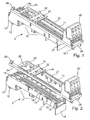
- Fig. 1 shows a device adapter 1 with a base part 10 and a built-up device 20 with two longitudinally spaced on the longitudinal edges of the base member 10 arranged longitudinal strips 21, 24 and connecting them cross bars 25, 26.
- On the longitudinal strips 21, 24 is for easy attachment of devices or Installation units a the distance between the two longitudinal strips bridging attachment part 30 in the form of a DIN rail with its base on the top of the longitudinal strips 21, 24 placed and fixed thereto by means of fastening means 32 in the form of screws, as well as the Fig. 2 . 3 . 5 and 6 demonstrate.
- the attachment 30 Before the attachment 30 is fixed in its end-valid position, it is fixed on the longitudinal strips by means of downwardly projecting latching retaining elements 31 to this and can be moved along the longitudinal strips 21, 24 in the desired position become.
- connection unit 40 is attached to a section projecting beyond the one end side of the essentially cuboid base part 10 by means of screws which are perpendicular to the upper side of the building device 20 or the device adapter 1 into the longitudinal strips 21, 24 engage inserted holes.
- the holes form in the longitudinal strips 21, 24 a respective row of holes with a specific grid.
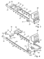
- the longitudinal strips 21 are introduced with the suspension elements 22 perpendicular to the top of the base member 10 in the receiving openings 13 and then moved in the longitudinal direction of the base member 10, so that the likewise in the direction of displacement projecting hook parts are brought into their holding position.
- this is fixed by means of a locking element 28 on a longitudinal bar 24 or alternatively both longitudinal strips 21, 24 by means of a pin-like locking element 28 against displacement, wherein the locking element 28 with a shaft part in one on the top of the base part 10 incorporated at the appropriate place locking element 19 preferably detent engages.
- the relevant longitudinal bar 24 is this, as in particular from Fig.
- the longitudinal strips 21, 24 are provided on their mutually facing sides with aligned transverse pins 24.1, 24.2 for connecting to the transverse strips 25, 26.
- the transverse strips 25, 26, which advantageously have the same cross-section as the longitudinal strips 21, 24, provided at least in their end portions with the cross-section of the transverse pins 24.1, 24.2 in cross section adapted cavities 25.2, 26.2.
- the mounting device 20 can be pre-assembled before installation on the base part 10 by means of simple plug-in mounting, whereby the attachment of the mounting device 20 on the base part 10 can be easily made.
- the transverse strips 25, 26 are provided on their underside with retaining legs 25.1, 26.1 formed thereon, which may additionally be equipped with locking elements for fixing to the base part 10 and interact with counter-holding elements of the base part 10.
- a triangular-shaped, rectangular support means 27 is arranged on its side the end wall 18 facing side is provided with a holding structure 27.1 in the form of an integrally formed, in cross-section T-shaped or dovetailed rib, which is arranged in a arranged on the end face of the base part 10 complementary Holding means 15 engages in the form of an undercut T-groove.
- the support means 27 is inserted with its support structure 27.1 in the support means receptacle 15 and then applied the mounting device 20 and hooked.
- the terminal unit 40 can be connected by the longitudinal strips 21, 24 with fastening screws also with the support means 27.
- FIG. 1 and 2 further show, three rail receivers 11 are formed on the underside of the base part 10, in which transversely to the base member 10 and the device adapter 1 extending busbars can be added.
- the rail receivers are separated from one another by means of boundary walls 17 running transversely to the base part 10.
- For contacting with the busbars 11 Jardinierabête 60 for-the electrical contacting of the busbars are arranged on the underside of the base part 10 in the rail receptacles.
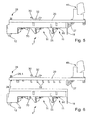
- hook parts 55 can be fixed for attachment of the device adapter 1 to the busbars 55, such as Fig. 5 shows.
- To lock the applied on the busbar device adapter 1 is in at least one rail mount 11, such as Fig.
- the base part 10 shows a stepped, in the base part 10 against a spring force retractable locking element 70 is provided.
- the locking element 70 can be unlocked by means of a on the upper side of the base member 10 at one end portion projecting handle 50, so that the device adapter 1 can be removed from the busbars.
- the base part 10 also has at least one hook-shaped retaining means 12 on the underside of its one end section.
- the handle 50 for the locking element 70 which is a longitudinal bar 21 shortened at the respective end portion, so that the handle 50 can be easily arranged and operated in this area.
Landscapes
- Engineering & Computer Science (AREA)
- Power Engineering (AREA)
- Mutual Connection Of Rods And Tubes (AREA)
- Connection Of Plates (AREA)
- Connections Arranged To Contact A Plurality Of Conductors (AREA)
- Installation Of Bus-Bars (AREA)
- Details Of Connecting Devices For Male And Female Coupling (AREA)
- Conveying And Assembling Of Building Elements In Situ (AREA)
Description
Die Erfindung bezieht sich auf einen Geräteadapter mit einem Basisteil, das auf seiner Unterseite mit Schienenaufnahmen zum Anbringen und Kontaktieren an Stromsammelschienen versehen ist und auf seiner Oberseite eine mit Verbindungsmitteln lösbar befestigte Aufbauvorrichtung mit zwei parallel voneinander beabstandeten Längsleisten zum Ankoppeln elektrischer Geräte oder Installationseinheiten trägt.The invention relates to a device adapter with a base part, which is provided on its underside with rail receptacles for attaching and contacting on busbars and carries on its upper side with a releasably fastened connection means with two mounting devices arranged parallel spaced longitudinal bars for coupling electrical equipment or installation units.
Ein Geräteadapter dieser Art ist in der
Auch in der
Aus der
Der Erfindung liegt die Aufgabe zugrunde, einen Geräteadapter der eingangs genannten Art bereitzustellen, der bei einfachem Aufbau und einfacher Handhabung variable Montagemöglichkeiten bietet.The invention has for its object to provide a device adapter of the type mentioned above, which offers variable mounting options with a simple structure and ease of use.
Diese Aufgabe wird mit den Merkmalen des Anspruches 1 gelöst. Hierbei ist vorgesehen, dass die Verbindungsmittel als auf der Unterseite der Längsleisten angeformte, vorstehende, hakenartige Einhängeelemente ausgebildet sind, die in daran angepasste Aufnahmeöffnungen auf der Oberseite des Basisteils senk-recht einführbar und durch eine Verschiebung in Längsrichtung im Bereich hinter den Aufnahmeöffnungen auf deren von der Oberseite abgelegenen Seite einhängbar sind, und dass zum Arretieren der eingehängten Stellung der Längsleisten ein freigebbares Arretierelement vorhanden ist. Mit diesen Maßnahmen können die Längsleisten auf einfache Weise auf der Oberseite des Basisteils montiert und auch gelöst werden.This object is achieved with the features of
Dabei bestehen für die Fertigung und die Handhabung günstige Ausgestaltungsvarianten darin, dass die Einhängeelemente in Verschieberichtung vorstehende Endabschnitte aufweisen oder dass die Einhängeelemente verbreiterte Endabschnitte aufweisen und die Aufnahmeöffnungen als in Längsrichtung ausgerichtete schlüssellochförmige Öffnungen ausgebildet sind. Mit dem Arretierelement werden die Längsleisten in ihrer Montagestellung zuverlässig gesichert.In this case, there are favorable design variants for the production and handling that the suspension elements projecting in the direction of displacement Have end portions or that the Einhängeelemente have widened end portions and the receiving openings are formed as aligned in the longitudinal direction keyhole-shaped openings. With the locking element, the longitudinal strips are reliably secured in their mounting position.
Zu einer einfachen Handhabung tragen dabei die Maßnahmen bei, dass das Arretierelement als entnehmbarer steckbarer und/oder verrastbarer Stift, der senkrecht von der Oberseite durch eine angepasste Durchführöffnung der betreffenden Längsleiste in eine angepasste, in der eingehängten Stellung fluchtende Arretierelementaufnahme einsetzbar ist, oder dass das Arretierelement als an der Längsleiste oder dem Basisteil angeformtes Rastelement ausgebildet ist, das in ein Rastgegenelement an dem Basisteil oder der Längsleiste eingreift.To a simple handling thereby contribute to the measures that the locking element as a removable pluggable and / or lockable pin, which is perpendicular from the top through an adapted passage opening of the relevant longitudinal bar in a customized, aligned in the mounted position Arretierelementaufnahme, or that Locking element is formed as formed on the longitudinal bar or the base part locking element which engages in a locking counter-element on the base part or the longitudinal bar.
Ist vorgesehen, dass die beiden auf den seitlichen Randbereichen des Basisteils angebrachten oder anzubringenden Längsleisten über zwei lösbare Querleisten mitein-ander verbunden sind, kann eine Einheit aus den beiden Längsleisten und den Querleisten vormontiert und einfach auf dem Basisteil angebracht werden.If it is provided that the two longitudinal strips attached or to be attached to the lateral edge regions of the base part are connected to one another via two detachable transverse strips, a unit of the two longitudinal strips and the transverse strips can be preassembled and easily mounted on the base part.
Eine einfache Fertigung und Handhabung wird dadurch begünstigt, dass die Querleisten entsprechenden Querschnitt wie die Längsleisten aufweisen und an den beiderseitigen Endabschnitten auf ihrer Unterseite senkrecht nach unten vorstehende Halteschenkel aufweisen.A simple production and handling is favored by the fact that the transverse strips have the corresponding cross-section as the longitudinal strips and have at the mutual end portions on their underside vertically downwardly projecting retaining legs.
Ferner tragen zu einer einfachen, stabilen Montage die Maßnahmen bei, dass auf den einander zugekehrten Innenseiten der Längsleisten in aufeinander abgestimmter Position gegeneinander gerichtete Querzapfen angeformt sind und dass die Querleisten zumindest in ihren Endabschnitten in ihrer Längsrichtung verlaufende, am Ende offene und in ihrem Querschnitt an den Querschnitt der Querzapfen angepasste Hohlräume zum Einstecken der Querzapfen aufweisen.Furthermore, contribute to a simple, stable assembly measures that are formed on the facing inner sides of the longitudinal strips in a coordinated position against each other directed transverse pin and that the transverse strips at least in their end portions extending in the longitudinal direction, open at the end and in its cross section Have the cross-section of the transverse pin adapted cavities for inserting the transverse pin.
Ist des Weiteren vorgesehen, dass die beiden Längsleisten im angebrachten Zustand mit Endabschnitten das Basisteil auf einer Stirnseite überragen und dass in dem Winkelbereich zwischen der Stirnseite des Basisteils und der Unterseite der Längsleiste ein Stützmittel angebracht ist, ergeben sich auch auf dem überstehenden Teil der Längsleisten Montagemöglichkeiten. Hierbei wird die Stabilität durch das Stützmittel gesteigert.Is further provided that the two longitudinal strips in the attached state with end portions project beyond the base part on an end face and that in the angular region between the end face of the base part and the underside of the longitudinal bar a support means is mounted, resulting also on the protruding part of the longitudinal strips mounting options , In this case, the stability is increased by the proppant.
Eine einfache, stabile Anbringung mit dem Stützmittel ergibt sich dabei dadurch, dass das Stützmittel auf seiner der Stirnseite des Basisteils zugekehrten Seite mit einer Haltestruktur versehen ist, die im angebrachten Zustand der Längsleisten in eine jeweilige zu ihr komplementäre Stützmittelaufnahme in Eingriff gebracht ist.A simple, stable attachment to the support means results from the fact that the support means is provided on its the front side of the base side facing side with a support structure which is brought in the attached state of the longitudinal strips in a respective complementary thereto support means receiving.
Eine vorteilhafte Ausgestaltung für die Handhabung des Geräteadapters besteht ferner darin, dass eine Längsleiste im angebrachten Zustand mit ihrem einen Ende um einen bestimmten Abstand vor der betreffenden Stirnseite des Basisteils endet und dass in dem freigelassenen Abschnitt des Basisteils eine Handhabe zum Betätigen eines Riegels des Geräteadapters angeordnet ist.An advantageous embodiment for the handling of the device adapter further consists in that a longitudinal bar in the attached state ends with its one end by a certain distance in front of the relevant end face of the base part and that arranged in the released portion of the base part a handle for actuating a bolt of the device adapter is.
Ein einfaches Ankoppeln von Geräten oder Installationseinheiten wird dadurch begünstigt, dass auf der Oberseite der beiden parallel beabstandeten Längsleisten ein den Parallelabstand überbrückendes Aufsatzteil zum Ankoppeln von Geräten oder Installationseinheiten in Längsrichtung entlang den Längsleisten verschiebbar eingerastet ist und mittels Befestigungsmitteln in einer wählbaren Position auf den Längsseiten festlegbar ist.A simple coupling of devices or installation units is facilitated by the fact that on the top of the two parallel spaced longitudinal strips a parallel distance bridging attachment for coupling devices or installation units in the longitudinal direction along the longitudinal strips slidably engaged and fixed by means of fasteners in a selectable position on the long sides is.
Die Erfindung wird nachfolgend anhand von Ausführungsbeispielen unter Bezugnahme auf die Zeichnungen näher erläutert. Es zeigen:
- Fig. 1
- einen Geräteadapter mit aufgebrachter Aufbauvorrichtung in perspektivischer Ansicht,
- Fig. 2
- den Geräteadapter nach
Fig. 1 mit abgenommener Aufbauvorrichtung in perspektivischer Ansicht, - Fig. 3
- die in den
Fig. 1 und 2 gezeigte Aufbauvorrichtung in perspektivischer Ansicht, - Fig. 4
- die Aufbauvorrichtung nach
Fig. 3 in auseinander genommener, perspektivischer Darstellung, - Fig. 5
- eine seitliche Ansicht des Geräteadapters nach
Fig. 1 mit Hakenteilen zum Anbringen an Stromsammelschienen und - Fig. 6
- den Geräteadapter nach
Fig. 5 mit abgenommener Aufbauvorrichtung.
- Fig. 1
- a device adapter with applied construction device in perspective view,
- Fig. 2
- the device adapter
Fig. 1 with removed mounting device in perspective view, - Fig. 3
- in the
Fig. 1 and 2 shown construction device in perspective view, - Fig. 4
- the building device after
Fig. 3 taken apart, perspective view, - Fig. 5
- a side view of the device adapter after
Fig. 1 with hook parts for attachment to busbars and - Fig. 6
- the device adapter
Fig. 5 with removed construction device.
Wie insbesondere aus den
Wie die
Wie aus den Fig. weiterhin ersichtlich, ist in dem Winkelbereich zwischen den über die betreffende Stirnseite des Basisteils 10 vorstehenden Endabschnitten der Längsleisten 21, 24 und der stirnseitigen Abschlusswand 18 des Basisteils 10 ein in seitlicher Ansicht dreieckförmiges, rechtwinkliges Stützmittel 27 angeordnet, das auf seiner der Abschlusswand 18 zugekehrten Seite mit einer Haltestruktur 27.1 in Form einer angeformten, im Querschnitt T-förmigen oder schwalbenschwanzförmigen Rippe versehen ist, die in eine an der Stirnseite des Basisteils 10 angeordnete komplementäre Haltemittelaufnahme 15 in Form einer hinterschnittenen T-Nut eingreift. Bei der Montage wird vorteilhaft zuerst das Stützmittel 27 mit seiner Haltestruktur 27.1 in die Stützmittelaufnahme 15 eingeschoben und anschließend die Aufbauvorrichtung 20 aufgebracht und festgehakt. Wie z.B.
Wie die
Um die Handhabe 50 für das Verriegelungselement 70 einfach bedienen zu können, ist die eine Längsleiste 21 an dem betreffenden Endabschnitt verkürzt, so dass die Handhabe 50 in diesem Bereich problemlos angeordnet und betätigt werden kann.In order to easily operate the
Claims (10)
- A device adapter comprising a base part (10), the bottom side of which is provided with bus bar receptacles to be mounted on and contacted with bus bars while the top side thereof supports a mounting device (20) that is removably fixed with the aid of connecting means and is equipped with two parallel spaced-apart longitudinal rails (21, 24) for coupling electric devices or house wiring units (40), wherein the connecting means are embodied as protruding, hook-type hanging elements (22) molded onto the bottom side of the longitudinal rails (21, 24) which can be vertically inserted into receiving holes (13) that are adjusted thereto and are located on the top side of the base part (10), characterized in that the longitudinal rails can be hung on the side of the receiving holes (22) facing away from the top side in the area behind the receiving holes (22) by performing a translation movement in the longitudinal direction and that a releasable locking element (28) is provided for locking the hung position of the longitudinal rails (21, 24).
- The device adapter of claim 1, characterized in that the hanging elements (22) comprise end sections protruding in the translation direction or that the hanging elements (22) comprise enlarged end sections and the receiving openings (22) are embodied as key hole shaped openings aligned in the longitudinal direction.
- The device adapter of claim 1 or 2, characterized in that the locking element (28) is embodied as a removable, pluggable and/or lockable pin, which can be inserted from the from the top side through an adjusted passing opening (24.3) of the respective longitudinal rail (24) perpendicularly into an adapted locking element receptacle (19) aligned in the hung-in position, or that the locking element is embodied as a latch element molded to the longitudinal rail (24) or to the base part (10) which engages into a locking counter element at the base part (10) or at the longitudinal rail (24).
- The device adapter of any of the preceding claims, characterized in that the two longitudinal rails (21, 24) attached to or being attachable to the lateral edge regions of the base part (10) are connected via two detachable transverse rails (25, 26).
- The device adapter of claim 4, characterized in that the transverse rails (25, 26) comprise a cross section corresponding to the longitudinal rails (21, 24) and comprise holding legs (25.1, 26.1) at both end sections on their bottom side which protrude vertically downwards.
- The device adapter of claim 4 or 5, characterized in that at the inner sides of the longitudinal rails (21, 24) facing towards another oppositely directed transfer posts (24.1, 24.2) are molded at adjusted positions and that the transverse rails (25, 26) comprise, at least in their end sections, cavities for plugging in the transverse posts (24.1, 24.2) which have open ends extending in longitudinal direction and are adjusted to the cross section of the transverse posts (24.1, 24.2).
- The device adapter of any of the preceding claims, characterized in that in an assembled state both longitudinal rails (21, 24) with end sections extend beyond the base part (10) at an end side thereof and that in the angular region between the end side of the base part (10) and the bottom side of the longitudinal rail a supporting means (27) is mounted.
- The device adapter of claim 7, characterized in that the supporting means (27) is provided with a holding structure (27.1) on a side facing to the end side of the base part (10), which holding structure is, in an assembled state of the longitudinal rails (21, 24), engaged with a supporting means receptacle (15) complementary thereto.
- The device adapter of any of the preceding claims, characterized in that a longitudinal rail (21) terminates, in an assembled state, with one of its ends at a predetermined distance of the respective end side of the base part (10) and that a manipulating means (50) is arranged in the exposed section of the base part (30) for actuating of a lock of the device adapter.
- The device adapter of any of the preceding claims, characterized in that a top piece (30) bridging the parallel distance of the parallel spaced longitudinal rails (21, 24) for coupling of devices or installation units in longitudinal direction along the longitudinal rails (21, 24) is slidably latched on the top side of the longitudinal rails and may be attached with the aid of attachment means (32) in a selectable position on the longitudinal rails (21, 24).
Priority Applications (1)
| Application Number | Priority Date | Filing Date | Title |
|---|---|---|---|
| PL06706798T PL1859518T3 (en) | 2005-03-04 | 2006-02-10 | Device adapter |
Applications Claiming Priority (2)
| Application Number | Priority Date | Filing Date | Title |
|---|---|---|---|
| DE102005009993A DE102005009993B3 (en) | 2005-03-04 | 2005-03-04 | Electric adapter for coupling up appliances has a base part with rail pick-ups on its underside for contacting current bus bars and lengthwise strips on its upper side for coupling up appliances |
| PCT/EP2006/001167 WO2006094595A1 (en) | 2005-03-04 | 2006-02-10 | Device adapter |
Publications (2)
| Publication Number | Publication Date |
|---|---|
| EP1859518A1 EP1859518A1 (en) | 2007-11-28 |
| EP1859518B1 true EP1859518B1 (en) | 2012-09-19 |
Family
ID=36143449
Family Applications (1)
| Application Number | Title | Priority Date | Filing Date |
|---|---|---|---|
| EP06706798A Active EP1859518B1 (en) | 2005-03-04 | 2006-02-10 | Device adapter |
Country Status (7)
| Country | Link |
|---|---|
| US (1) | US7520776B2 (en) |
| EP (1) | EP1859518B1 (en) |
| JP (1) | JP2008509511A (en) |
| CN (1) | CN101133533B (en) |
| DE (1) | DE102005009993B3 (en) |
| PL (1) | PL1859518T3 (en) |
| WO (1) | WO2006094595A1 (en) |
Families Citing this family (12)
| Publication number | Priority date | Publication date | Assignee | Title |
|---|---|---|---|---|
| DE202006006469U1 (en) * | 2005-10-20 | 2007-03-01 | Weidmüller Interface GmbH & Co. KG | Pre-assembled electrical installation unit |
| DE102006042947A1 (en) * | 2006-09-13 | 2008-03-27 | Siemens Ag | DIN rail carrier and DIN rail with two DIN rail carriers |
| DE102008014177A1 (en) * | 2008-03-14 | 2009-09-17 | Phoenix Contact Gmbh & Co. Kg | Terminal block and terminal block |
| US8547684B2 (en) * | 2009-12-17 | 2013-10-01 | Schneider Electric USA, Inc. | Panelboard having a parallel feeder bars distribution |
| DE102011052381B4 (en) * | 2011-08-03 | 2013-04-18 | Rittal Gmbh & Co. Kg | Busbar adapter with a mounting rail for mounting a switching device |
| DE102012014980A1 (en) * | 2012-07-25 | 2014-05-15 | Friedrich Lütze GmbH | Mounting system for the arrangement of, for example, electrical devices, especially in cabinets |
| US9397462B2 (en) * | 2012-12-28 | 2016-07-19 | General Electric Company | Rail mounting system and detaching method |
| CN104938042B (en) * | 2013-01-15 | 2018-09-14 | 威德米勒界面有限公司及两合公司 | Equipment with module and electronic device and equipment |
| DE102013110788B4 (en) | 2013-09-30 | 2015-12-03 | Klaus Bruchmann Gmbh | Busbar adapter |
| DE102013111857B4 (en) * | 2013-10-28 | 2015-05-13 | Klaus Bruchmann Gmbh | Secured busbar adapter |
| DE102014105955B4 (en) * | 2014-04-29 | 2015-12-24 | Phoenix Contact Gmbh & Co. Kg | Mounting arrangement for terminal blocks |
| DE202016100307U1 (en) * | 2016-01-22 | 2017-04-26 | Weidmüller Interface GmbH & Co. KG | Series device arrangement with a power bus system |
Family Cites Families (6)
| Publication number | Priority date | Publication date | Assignee | Title |
|---|---|---|---|---|
| US4387872A (en) * | 1981-01-17 | 1983-06-14 | Packard Industries, Inc. | Latch for a tab and slot mounting bracket |
| US4916574A (en) * | 1989-06-06 | 1990-04-10 | Siemens Energy & Automation, Inc. | Panelboard bus bar arrangement |
| US5178555A (en) * | 1991-10-02 | 1993-01-12 | Amp Incorporated | Installation of junction boxes along a raceway |
| DE19755848C2 (en) * | 1997-12-15 | 2002-07-18 | Rittal Gmbh & Co Kg | Multi-function adapter for a number of busbars in a busbar system |
| DE29811379U1 (en) * | 1998-06-25 | 1998-09-10 | Rittal-Werk Rudolf Loh Gmbh & Co Kg, 35745 Herborn | Device adapter with adjustable and lockable device carrier |
| DE10005818A1 (en) * | 2000-02-10 | 2001-08-16 | Moeller Gmbh | Device for mounting switchgear on mounting rails |
-
2005
- 2005-03-04 DE DE102005009993A patent/DE102005009993B3/en active Active
-
2006
- 2006-02-10 PL PL06706798T patent/PL1859518T3/en unknown
- 2006-02-10 EP EP06706798A patent/EP1859518B1/en active Active
- 2006-02-10 WO PCT/EP2006/001167 patent/WO2006094595A1/en not_active Application Discontinuation
- 2006-02-10 US US11/667,809 patent/US7520776B2/en active Active
- 2006-02-10 JP JP2007524356A patent/JP2008509511A/en active Pending
- 2006-02-10 CN CN2006800070794A patent/CN101133533B/en active Active
Also Published As
| Publication number | Publication date |
|---|---|
| PL1859518T3 (en) | 2013-01-31 |
| DE102005009993B3 (en) | 2006-06-14 |
| US7520776B2 (en) | 2009-04-21 |
| JP2008509511A (en) | 2008-03-27 |
| CN101133533B (en) | 2010-06-23 |
| CN101133533A (en) | 2008-02-27 |
| WO2006094595A1 (en) | 2006-09-14 |
| EP1859518A1 (en) | 2007-11-28 |
| US20080002338A1 (en) | 2008-01-03 |
Similar Documents
| Publication | Publication Date | Title |
|---|---|---|
| EP1859518B1 (en) | Device adapter | |
| DE3643559C2 (en) | Installation box that can be fastened in a parapet duct | |
| EP1431765A2 (en) | Apparatus for coupling an electric energy meter to a support platform | |
| EP2171817A1 (en) | Apparatus for arranging and fastening electrical units in particular in a switchgear cabinet, and a fitting system with such an apparatus | |
| EP3461963B1 (en) | Supporting construction system and system of connecting elements for the supporting construction | |
| EP1002166A1 (en) | Dividing wall especially for exhibition booths | |
| DE4034307C1 (en) | ||
| DE4438921C1 (en) | Mounting device for heavy electrical plug-connector inserts on carrier rail | |
| DE2810764C2 (en) | ||
| DE202017104115U1 (en) | Mount for receiving earth and / or compost material | |
| EP2863497B1 (en) | Distribution cabinet or electrical installation boxes of buildings | |
| DE3300729C2 (en) | ||
| EP0933853B1 (en) | Support for an outlet box flush mounted in a channel | |
| DE3326304C2 (en) | Base for cable distribution cabinets | |
| DE1905735A1 (en) | Suspended ceiling construction | |
| EP2657401B1 (en) | Laying plate | |
| DE102019104723B4 (en) | Control cabinet arrangement with a control cabinet and at least one power strip | |
| DE10135662A1 (en) | Equipment container frame for underground applications has supporting parts with clamp connecting, fixing arrangements that can be plugged into slots in latching guides at desired depth | |
| DE102008010205A1 (en) | rail | |
| DE60319315T2 (en) | Locking element for a grid on a drainage channel and tool for removing the same | |
| EP2372852A2 (en) | Meter- or distribution cabinet | |
| DE2439362C2 (en) | Support frame for a suspended ceiling | |
| DE2609448C3 (en) | Door stop strip for a plastic cable distribution cabinet | |
| DE2026512C3 (en) | Electrical outlet | |
| DE20215340U1 (en) | Mounting element for device installation trunking |
Legal Events
| Date | Code | Title | Description |
|---|---|---|---|
| PUAI | Public reference made under article 153(3) epc to a published international application that has entered the european phase |
Free format text: ORIGINAL CODE: 0009012 |
|
| 17P | Request for examination filed |
Effective date: 20071004 |
|
| AK | Designated contracting states |
Kind code of ref document: A1 Designated state(s): AT DE FR PL |
|
| DAX | Request for extension of the european patent (deleted) | ||
| RBV | Designated contracting states (corrected) |
Designated state(s): AT DE FR PL |
|
| GRAP | Despatch of communication of intention to grant a patent |
Free format text: ORIGINAL CODE: EPIDOSNIGR1 |
|
| GRAS | Grant fee paid |
Free format text: ORIGINAL CODE: EPIDOSNIGR3 |
|
| GRAA | (expected) grant |
Free format text: ORIGINAL CODE: 0009210 |
|
| AK | Designated contracting states |
Kind code of ref document: B1 Designated state(s): AT DE FR PL |
|
| REG | Reference to a national code |
Ref country code: AT Ref legal event code: REF Ref document number: 576427 Country of ref document: AT Kind code of ref document: T Effective date: 20121015 |
|
| REG | Reference to a national code |
Ref country code: DE Ref legal event code: R096 Ref document number: 502006011994 Country of ref document: DE Effective date: 20121115 |
|
| REG | Reference to a national code |
Ref country code: PL Ref legal event code: T3 |
|
| PLBE | No opposition filed within time limit |
Free format text: ORIGINAL CODE: 0009261 |
|
| STAA | Information on the status of an ep patent application or granted ep patent |
Free format text: STATUS: NO OPPOSITION FILED WITHIN TIME LIMIT |
|
| 26N | No opposition filed |
Effective date: 20130620 |
|
| REG | Reference to a national code |
Ref country code: DE Ref legal event code: R097 Ref document number: 502006011994 Country of ref document: DE Effective date: 20130620 |
|
| REG | Reference to a national code |
Ref country code: FR Ref legal event code: PLFP Year of fee payment: 11 |
|
| REG | Reference to a national code |
Ref country code: FR Ref legal event code: PLFP Year of fee payment: 12 |
|
| REG | Reference to a national code |
Ref country code: FR Ref legal event code: PLFP Year of fee payment: 13 |
|
| P01 | Opt-out of the competence of the unified patent court (upc) registered |
Effective date: 20230525 |
|
| PGFP | Annual fee paid to national office [announced via postgrant information from national office to epo] |
Ref country code: AT Payment date: 20240216 Year of fee payment: 19 |
|
| PGFP | Annual fee paid to national office [announced via postgrant information from national office to epo] |
Ref country code: DE Payment date: 20240216 Year of fee payment: 19 |
|
| PGFP | Annual fee paid to national office [announced via postgrant information from national office to epo] |
Ref country code: PL Payment date: 20240131 Year of fee payment: 19 Ref country code: FR Payment date: 20240221 Year of fee payment: 19 |