EP1857597A2 - Procédé et dispositif de fonçage pour insérer des pieux de fondation dans le sol - Google Patents
Procédé et dispositif de fonçage pour insérer des pieux de fondation dans le sol Download PDFInfo
- Publication number
- EP1857597A2 EP1857597A2 EP07075384A EP07075384A EP1857597A2 EP 1857597 A2 EP1857597 A2 EP 1857597A2 EP 07075384 A EP07075384 A EP 07075384A EP 07075384 A EP07075384 A EP 07075384A EP 1857597 A2 EP1857597 A2 EP 1857597A2
- Authority
- EP
- European Patent Office
- Prior art keywords
- pile
- base plate
- pipe
- ground
- pipe segment
- Prior art date
- Legal status (The legal status is an assumption and is not a legal conclusion. Google has not performed a legal analysis and makes no representation as to the accuracy of the status listed.)
- Withdrawn
Links
Images


Classifications
-
- E—FIXED CONSTRUCTIONS
- E02—HYDRAULIC ENGINEERING; FOUNDATIONS; SOIL SHIFTING
- E02D—FOUNDATIONS; EXCAVATIONS; EMBANKMENTS; UNDERGROUND OR UNDERWATER STRUCTURES
- E02D7/00—Methods or apparatus for placing sheet pile bulkheads, piles, mouldpipes, or other moulds
- E02D7/02—Placing by driving
-
- E—FIXED CONSTRUCTIONS
- E02—HYDRAULIC ENGINEERING; FOUNDATIONS; SOIL SHIFTING
- E02D—FOUNDATIONS; EXCAVATIONS; EMBANKMENTS; UNDERGROUND OR UNDERWATER STRUCTURES
- E02D3/00—Improving or preserving soil or rock, e.g. preserving permafrost soil
- E02D3/02—Improving by compacting
- E02D3/08—Improving by compacting by inserting stones or lost bodies, e.g. compaction piles
-
- E—FIXED CONSTRUCTIONS
- E02—HYDRAULIC ENGINEERING; FOUNDATIONS; SOIL SHIFTING
- E02D—FOUNDATIONS; EXCAVATIONS; EMBANKMENTS; UNDERGROUND OR UNDERWATER STRUCTURES
- E02D5/00—Bulkheads, piles, or other structural elements specially adapted to foundation engineering
- E02D5/66—Mould-pipes or other moulds
-
- E—FIXED CONSTRUCTIONS
- E02—HYDRAULIC ENGINEERING; FOUNDATIONS; SOIL SHIFTING
- E02D—FOUNDATIONS; EXCAVATIONS; EMBANKMENTS; UNDERGROUND OR UNDERWATER STRUCTURES
- E02D5/00—Bulkheads, piles, or other structural elements specially adapted to foundation engineering
- E02D5/72—Pile shoes
Definitions
- the present invention relates to a method for inserting foundation piles into the ground.
- the method comprises the following steps:
- US 3,131,543 discloses such a method.
- various pipe segments that are telescopically connected to each other are first driven into the ground together with a base plate by means of a pile-driving hammer.
- the pile-driving hammer is of a cylindrical shape and increases stepwise in diameter, in such a way as to produce shoulders which during the pile driving rest upon the edges of the various pipe segments.
- the telescopic extension of the pipe segments will cause the pile-driving hammer in each case to be brought into ramming contact with the edges of the pipe segments having a larger diameter. As a result of this, the pipe segments will sink increasingly further into the ground.
- a disadvantage of this method is that the method is inefficient and expensive.
- a further disadvantage of this method is that the edges and the walls of the pipe segments are damaged by the pile-driving hammer ramming the edges.
- the damage to the edges of the pipe segments causes the various pipe segments to become jammed in one another.
- pile-driving hammer is quite long, with the result that the pile-driving hammer is difficult to handle in use.
- the great length of the pile-driving hammer is a problem.
- the pile-driving hammer is composed of a number of machined parts, the production of a large pile-driving hammer is expensive, which is reflected in the overall cost of the pile-driving work.
- a pile-driving hammer made up of a number of parts furthermore has the disadvantage that the project takes longer because of the working time required for assembly of the pile-driving hammer.
- the object of the present invention is at least partially to overcome at least one of the abovementioned disadvantages, or to provide a useful alternative.
- the object of the invention is to provide an effective and a cost-saving method of inserting foundation piles into the ground, in which method the risk of damage to the pipe segments is considerably reduced.
- the invention is characterized in that the method furthermore comprises the following steps: withdrawing the pipe segments from the ground using a withdrawal element, so that a hole is left in the ground; leaving the base plate behind in the hole that is left; and introducing a setting substance on top of the base plate in the hole that is left. After the substance has set, a foundation pile is obtained in the ground.
- the advantage of the base plate being left behind in the hole which is left in the ground after the withdrawal of the pipe segments and the advantage of setting substance being introduced on top of the base plate is that the base plate contributes to the bearing capacity of the foundation pile obtained.
- a flat base plate is preferably used because a greater bearing capacity is obtained with a flat base plate. If foundation piles with a greater bearing capacity are inserted, fewer foundation piles will be needed. This again is cost-saving.
- a pile-driving hammer that can also be used as the withdrawal element is used.
- the pile-driving hammer is provided with at least one connecting element for withdrawal of the pipe segments.
- the connecting element on the withdrawal element is preferably equipped to engage in a bayonet opening in at least one of the pipe segments, in order to form a bayonet closure.
- the pipe segment is withdrawn from the ground.
- the withdrawn pipe segment can be reused for inserting the next foundation pile.
- the withdrawal of the pipe segments from the ground by means of a bayonet closure is a simple and reliable procedure, so that the risk of damage to the pipe segments is small.
- the connecting element is preferably positioned on the distal end of the withdrawal element and is preferably in the form of a pin. At least one pin projects radially beyond the withdrawal element and will come into contact with the circumferential edge of a pipe segment when the withdrawal element is lowered.
- the edges of the pipe segments comprise slanting edge parts, in such a way that the pins of the withdrawal element are driven in the direction of the bayonet opening in the pipe segment. This will cause the withdrawal element to rotate slightly as it moves down.
- the pins engage in the bayonet opening of a pipe segment in such a way that the pipe segment moves up along with the withdrawal element.
- At least one movable connecting element is provided.
- the connecting element is movable in the radial direction from a first position, in which the connecting element lies back, to a second position, in which the connecting element engages upon the pipe segment to be withdrawn.
- the wall part preferably extends over the inside wall of the pipe segment around the entire circumference, so that turning of the withdrawal element does not affect the engagement of the connecting element upon the pipe segment.
- the connecting element preferably comprises a pin that is movable in the radial direction through the fact that the pin is provided with a slanting edge which interacts with a wedge-shaped element.
- Moving the wedge-shaped element up or down in the axial direction of the pipe segment enables the connecting element to move in the radial direction.
- Moving the wedge-shaped element up or down can be achieved, for example, by moving up or down a shaft which extends in the axial direction of the pipe segment and is connected to the wedge-shaped element.
- the shaft is preferably provided with a screw thread profile, so that the shaft can be moved up and down by means of a nut. Providing the withdrawal element with such a construction makes it possible to move the connecting element easily and reliably in the radial direction.
- the pile-driving hammer in the first instance rams the base plate, in such a way that the base plate drops a certain distance.
- the pile-driving hammer rams the pipe segment, in such a way that the pipe segment also moves down.
- the total ramming energy is transmitted by the pile-driving hammer to the pipe segments and the base plate. It is advantageous that most of the total ramming energy is dissipated by the base plate. This means that the ramming energy is used effectively to achieve a certain depth in the ground.
- lighter pile-driving devices will be needed for inserting the pipe segments into the ground.
- the lighter pile-driving devices are not only cheaper, but can also be used in situations in which the space or height for placing a pile-driving device is limited, or in which minimal ground damage is permitted.
- a small part of the total ramming energy is used for moving the pipe segments down. Moving the pipe segments down takes less energy because a hole has already been created in the ground by the base plate. Owing to the fact that the pile-driving hammer rams the pipe segment only in the second instance, the ramming energy dissipated by the pipe segment is considerably less than the ramming energy dissipated by the base plate. The risk of the pipe segment being damaged is significantly reduced. Furthermore, the risk of two telescopically connected pipe segments being inseparably jammed together is considerably reduced. The pipe segments can advantageously be reused more often.
- a further advantage is that the pipe segments can be made with thinner walls, which makes the pipe segments cheaper to produce. Moreover, materials other than steel, for example aluminium or plastic, can be used for the pipe segments.
- a reinforcing element can be supplied in one step.
- the reinforcing element can be, for example, a reinforced concrete steel construction, drill rods, a steel cable etc.
- the reinforcing element can be fed into the hole left in the ground after the withdrawal of the pipe segments.
- the setting substance can then be introduced.
- the withdrawal element is preferably used for positioning and guiding the reinforcing element into the hole in the ground.
- through holes can be provided in the withdrawal element, through which holes concrete steel rods, for example, can be inserted, which concrete steel rods are then left behind as a reinforcing element in the hole in the ground when the withdrawal element is withdrawn.
- the reinforcing elements can be guided down to the bottom of the hole, but they can also, for example, be guided halfway down the hole in the ground. In this way a foundation pile that is partially provided with a reinforcement, for example in the top half, can be obtained. After the infeed and setting of the setting substance, a foundation pile with reinforcement is obtained.
- a pile-driving device with specific device features is used for inserting foundation piles into the ground.
- the invention also relates to a pile-driving device.
- the pile-driving device preferably comprises a hoisting winch for moving the pile-driving hammer up.
- the hoisting winch is a simple and reliable solution, which increases the usability of the method according to the invention in widely different circumstances.
- the hoisting winch is preferably also used for withdrawing the pipe segments from the ground.
- a pneumatically or hydraulically driven pile-driving hammer or a vibrating unit for vibrating the pipe segments into the ground can also be used.
- the pile-driving hammer for use in the method according to the invention is provided with a ramming face, which is equipped to ram the base plate in a base plate ramming zone. Furthermore, the pile-driving hammer comprises a collar with a collar face, which is equipped to ram the pipe segment in a pipe segment ramming zone. The distance in the axial direction between the ramming face and the collar face is greater than the distance between the base plate ramming zone and the pipe segment ramming zone. The difference in distance is preferably greater than 2 cm. Through the difference in distance, the ramming energy will be fully utilized during the pile driving in the first instance for moving the base plate down. In the second instance the pile-driving hammer rams the pipe segment, with the result that the pipe segment will move down. Advantages of the method according to the invention already described above are achieved with the pile-driving hammer according to the invention.
- the pipe segments are preferably telescopically connected to each other in such a way that by pile driving on the inside pipe segment with the smallest diameter the larger pipe segments are driven along with it.
- a major advantage is that the pile-driving hammer is of relatively short length, so that the pile-driving hammer is easy to handle in use.
- the length of the pile-driving hammer is preferably a maximum of 3 metres. This means that the pile-driving hammer can be used in circumstances where the working space is limited.
- the pile-driving hammer is equipped as a withdrawal element and is furthermore provided with a feed-through channel.
- the pile-driving hammer can serve as a means for introducing the setting substance.
- the hole that is left in the ground is filled with the setting substance.
- a supply line preferably a supply hose, for supplying setting substance is connected to the pile-driving hammer. The setting substance will pass through the feed-through channel in the pile-driving hammer into the hole left in the ground.
- a sock is fixed over the distal end of the supply line.
- the sock is preferably made of an elastic material and rolled up over the distal end of the supply line.
- the advantage of using such a sock is that the setting substance introduced cannot be washed away into the ground. By means of the sock it is ensured that an unnecessarily large quantity of setting substance does not have to be introduced in order to obtain a foundation pile.
- the withdrawal element has at least one through hole around the feed-through channel, for the insertion of a reinforcing element.
- the base plate preferably comprises a collar with a diameter that is larger than the largest diameter of one of the pipe segments. This means that when the base plate is inserted into the ground a hole with a larger diameter than the largest diameter of the pipe segments is obtained. The pipe segments will consequently move more easily down into the ground and can be withdrawn more easily later. Furthermore, there is less of a risk that the hole made by the pile driving will partially cave in during the withdrawal of the pipe segments.
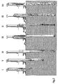
- Figure 1 shows an overall elevational view of the pile-driving device for use in the method according to the invention, in which foundation piles are inserted into the ground.
- the figure shows an above-ground machine 9 with a guide 8 and a hoisting winch 7.
- a foundation pipe system is positioned on the guide, above a base plate.
- the foundation pipe system has pipe segments 3 which are telescopically connected to each other.
- a pile-driving hammer 1 can be moved up and released, so that the pile-driving hammer 1 falls through the pipe segments and rams the base plate.
- the ramming will cause the base plate and the telescopically connected pipe segments to move down into the ground.
- FIG. 2 shows in a diagrammatic view a number of steps of the method according to the invention. The steps are indicated by Roman numerals I - VII.
- step I the foundation pipe system is positioned above a base plate.
- the pile-driving hammer is moved up and down by means of the winch.
- the pile-driving hammer ramming the base plate and the first pipe segment drives the base plate and the first pipe segment into the ground.
- step II The situation in which the first pipe segment goes into engagement with the second pipe segment is illustrated in step II. Through the engagement, the second pipe segment is taken along with the first pipe segment into the ground.
- step III The desired depth in the ground has been achieved in step III.
- the connection of a supply line to the pile-driving hammer is shown in step IV.
- the pile-driving hammer has a feed-through channel for feeding through a setting substance. Before it is moved down into the ground as a withdrawal element, the pile-driving hammer is provided with connecting elements.
- step V a connection is obtained between the pile-driving hammer as the withdrawal element and the first pipe segment.
- the withdrawal of the withdrawal element is shown in step VI.
- the withdrawal can be performed with the hoisting winch that is used during the pile driving, but in an alternative embodiment of the method an additional withdrawal element can also be provided. This can be advantageous, for example, when great forces which cannot be produced by the hoisting winch have to be generated during the withdrawal of the foundation pipe system.
- the withdrawal device can be, for example, a hydraulic device with hydraulic motors and cylinders.
- the pipe segments are withdrawn from the ground simultaneously with the withdrawal element, and a setting substance, for example concrete, is fed through the feed-through channel of the withdrawal element.
- the withdrawal element is preferably connected in a sealing manner to the inside of the first pipe segment, so that no groundwater or setting substance goes inside the pipe segment.
- the seal is obtained, for example, by a rubber ring situated around the outer circumference of the withdrawal element. The seal ensures that the foundation pipe system stays clean and can be reused easily after withdrawal from the ground.
- step VII the hole left after the foundation pipe system has been withdrawn is filled up completely with setting substance.
- a foundation pile is obtained by means of the method according to the invention.
- Figure 3 shows diagrammatically a detail view in section of the distal end of the pile-driving hammer 1 and the base plate 2 with a first pipe segment 3.1.
- the pile-driving hammer 1 has on the end face a ramming face 1a and a collar with a collar face 1b. During the pile driving the pile-driving hammer 1 will ram the base plate 2 with the ramming face 1a.
- the pile-driving hammer 1 in the second instance will ram the pipe segment 3.1 in a pipe segment ramming zone with the collar face 1b.
- the distance 'lv' on the pile-driving hammer between the collar face 1b and the ramming face 1a is greater than the distance 'la' on the foundation pipe system between the base plate ramming zone 2a and the pipe segment ramming zone 3.1b. In this way it is ensured that the ramming energy is used effectively for inserting the base plate 2 further into the ground, and the risk of damage to the pipe segment is reduced.
- the pipe segment 3.1 shown is of a thin-walled design, being reinforced at the position of the pipe segment ramming zone 3.1b for transmitting the ramming forces to the base plate 2.
- the base plate too is reinforced at the position of the base plate ramming zone 2a.
- the base plate is preferably of a flat design on the underside. After the pile driving and withdrawal of the pipe segments, the base plate is left behind in the ground. Compared with a pointed base plate, a flat base plate has the advantage that the bearing power of the foundation pile is considerably greater. This means that pipe segments with a smaller diameter will suffice, which results in lower costs. Moreover, a flat base plate has little self-locating capability, so that the pipe segments with the base plate do not tend to deviate in the wrong direction during insertion into the ground. In this way it is ensured that telescopic pipe segments which have gone askew do not become jammed in one another, which would make withdrawal from the ground difficult or totally impossible. If the telescopic pipe segments have gone askew, the risk of groundwater leaking into the pipe segments is greater. This risk is reduced with a flat base plate.
- the base plate preferably has a collar with a large external diameter 2d.
- the large external diameter is advantageous when inserting the pipe segments into and withdrawing them from the ground.
- the base plate 2 preferably has a raised edge 2b.
- the raised edge 2b ensures that the base plate remains positioned below the pipe segment 3.1.
- the base plate 2 is movable in the axial direction relative to the pipe segment 3.1.
- the raised edge 2b furthermore has a sealing effect and in this way ensures that during the movement hardly any groundwater penetrates into the pipe segment 3.1. Water must be prevented as far as possible from going into the pipe segment because this damps the movement of the pile-driving hammer.
- the raised edge 2b has an advantageous effect during withdrawal of the pipe segments if the raised edge 2b encloses the pipe segment 3.1.
- the raised edge ensures that less soil adheres to the pipe segment.
- the raised edge 2b is preferably at least 7 cm high.
- Figure 4 shows a simple embodiment of the base plate 2.
- the pile-driving hammer 1 is in ramming contact with the base plate 2, with the result that the base plate is displaced relative to the pipe segment.
- the pile-driving hammer is also in ramming contact with the pipe segment by way of the collar face 1b.
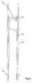
- Figure 5 shows in a view in detail two pipe segments 3.1 and 3.2.
- a flange is provided for a telescopic connection to a second pipe segment 3.2.
- the length of the pile-driving hammer can remain limited. In the embodiment shown the length of the pile-driving hammer is substantially determined by its weight and/or diameter.
- the collar face of the pile-driving hammer here comes into ramming contact with the proximal end of the first pipe segment 3.1.
- the ramming face of the pile-driving hammer comes into ramming contact with the base plate on the distal end of the pipe segment 3.1. It is advantageous here that the entire telescopic foundation pipe system can be inserted into the ground by means of only one collar face (1b) on the pile-driving hammer.
- the pile-driving hammer remains compact and consequently easy to handle.
- the length of the pile-driving hammer is preferably a maximum of 3 metres.
- the first pipe segment 3.1 can also have a pipe segment ramming zone 3.1b on the distal end. This is advantageous if the length of the pile-driving hammer has to remain limited to, for example, no more than 1 metre. Furthermore, this means that the pipe segment can be made with thinner walls, because the pipe segment is inserted into the ground by subjecting to a tensile load, and is subjected to little compressive load.
- Figure 5 also shows in the pipe segment 3 a bayonet opening 3a positioned in the proximal end.
- the bayonet opening 3a is formed by a slit lying in the axial direction and having a lead-in part 3b.
- a number of bayonet openings 3a are provided around the circumference of the proximal end of the pipe segment 3. This produces a pattern of hook-shaped projections around the circumference.
- the bayonet opening 3a is arranged in such a way that in the method according to the invention it interacts with a connecting element on the withdrawal element.
- the bayonet openings 3a shown in Figure 3 are equipped to interact with pin-shaped connecting elements on the withdrawal element.
- Figure 6 shows the distal end of a pipe segment 3.1 with a detachable part 2c.
- the detachable part 2c encloses the pipe segment 3.1 and is provided with various bayonet openings 3a.
- the pipe segment 3.1 will be withdrawn along with said detachable part.
- the pipe segments enclosing the pipe segment 3.1 will rest against the detachable part 2c and will also be withdrawn along with it out of the ground. It is advantageous that the pipe segments can be produced in a simple and therefore cost-effective manner.
- Figure 7 shows a detail view of the withdrawal element 4 to which a supply hose, which is provided with a sock 6, can be connected.
- the withdrawal element 4 is used in the method according to the invention for withdrawing the pipe segments 3 from the ground.
- a hole is left in the ground, which hole is filled up with setting substance.
- the rolled-up hose 6 on the distal end of the withdrawal element is filled with setting substance and prevents setting substance from being washed away into the ground.
- FIG. 8 shows two related views of a pile-driving hammer 1.
- the pile-driving hammer 1 is positioned inside a first pipe segment 3.1.
- the pile-driving hammer 1 has a ramming face 1a and a collar face 1b.
- the pile-driving hammer can also be used as a withdrawal element 4.
- the pile-driving hammer has a feed-through channel 23 for feeding through setting substance such as concrete.
- Controllable connecting elements 20, which serve to withdraw the pipe segments, are also provided.
- the connecting elements 20 comprise pins 21, which are provided with a wedge-shaped face and interact with wedge-shaped elements 22. When the wedge-shaped elements 22 move up the pins are pressed radially outwards.
- the radially projecting pins then engage upon a pipe segment and rest against a wall part 3.1c of the pipe segment extending in the radial direction, which part is obtained here by making a groove in such a way that the pipe segment can be drawn up along with the pins.
- the pipe segment 3.1 can also be provided with an upright wall part extending in the radial direction.
- the wedge-shaped elements 22 are connected here to at least one shaft 26.
- the shaft 26 is provided with a screw thread profile on the distal end. By rotating the shaft, the wedge-shaped element can be moved up and down in the axial direction of the pipe segment.
- the shaft 26 can be rigidly connected to the wedge-shaped element 22 and a screw thread profile is provided on the proximal end of the shaft. The shaft 26 can be moved up and down together with the wedge-shaped element 22 by means of a nut. All kinds of rotary or elevating constructions are conceivable for moving up the shaft 26 with wedge-shaped element 22.
- a groove is made near the distal end of the pile-driving hammer on the circumferential side, in which groove an inflatable band 25 is provided.
- the inflatable band 25 acts as a seal between the pile-driving hammer and the first pipe segment. This ensures that when setting substance is being fed through, the setting substance does not flow along the withdrawal element and soil the pipe segments.
- Figure 9 shows a view in cross section of the pile-driving hammer along the line IX-IX shown in Figure 8.
- the pile-driving hammer is provided with at least one through hole 24.
- four through holes 24 are provided for the purpose of placing reinforcing bars in the foundation pile.
- the holes are made in a regular, symmetrical pattern around the feed-through channel 23.
- Reinforcing elements such as concrete steel rods, strands or cables, can be placed through the holes.
- the reinforcing elements preferably have a diameter of no more than 15 mm and a length of no more than 12 m.
- the through holes 24 in the pile-driving hammer determine the ultimate position of the reinforcing elements in the foundation pile. This can prevent the reinforcing elements from becoming exposed and possibly becoming corroded. Furthermore, in this way the reinforcing elements can serve as a guide when withdrawing the withdrawal element.
- the base plate can be of a pointed design or can be composed of a number of parts.
- the foundation piles obtained according to the invention can have all kinds of cross sections.
- a foundation pile can have a round, square or oval cross section.
- the invention therefore provides a method in which the risk of damage to the pipe segments is considerably reduced, and in which, furthermore, a relatively simple, quick and cost-effective method for inserting foundation piles into the ground is provided.
Landscapes
- Engineering & Computer Science (AREA)
- Structural Engineering (AREA)
- Life Sciences & Earth Sciences (AREA)
- General Life Sciences & Earth Sciences (AREA)
- Mining & Mineral Resources (AREA)
- Paleontology (AREA)
- Civil Engineering (AREA)
- General Engineering & Computer Science (AREA)
- Agronomy & Crop Science (AREA)
- Environmental & Geological Engineering (AREA)
- Soil Sciences (AREA)
- Piles And Underground Anchors (AREA)
- Placing Or Removing Of Piles Or Sheet Piles, Or Accessories Thereof (AREA)
Applications Claiming Priority (2)
| Application Number | Priority Date | Filing Date | Title |
|---|---|---|---|
| NL1031849A NL1031849C1 (nl) | 2006-05-19 | 2006-05-19 | Werkwijze en hei-inrichting voor het in de grond aanbrengen van funderingspalen. |
| NL1033620A NL1033620C2 (nl) | 2006-05-19 | 2007-03-30 | Werkwijze en hei-inrichting voor het in de grond aanbrengen van funderingspalen. |
Publications (2)
| Publication Number | Publication Date |
|---|---|
| EP1857597A2 true EP1857597A2 (fr) | 2007-11-21 |
| EP1857597A3 EP1857597A3 (fr) | 2008-10-22 |
Family
ID=38291290
Family Applications (1)
| Application Number | Title | Priority Date | Filing Date |
|---|---|---|---|
| EP07075384A Withdrawn EP1857597A3 (fr) | 2006-05-19 | 2007-05-21 | Procédé et dispositif de fonçage pour insérer des pieux de fondation dans le sol |
Country Status (1)
| Country | Link |
|---|---|
| EP (1) | EP1857597A3 (fr) |
Cited By (8)
| Publication number | Priority date | Publication date | Assignee | Title |
|---|---|---|---|---|
| CN101591913B (zh) * | 2009-05-08 | 2010-09-15 | 裘苗全 | 围护桶套接式吊桩方法和设备 |
| NL2005758C2 (en) * | 2010-11-25 | 2012-05-29 | Johannes Cornelis Vliet | Method and set of piling tools for creating a pile in the ground. |
| NL2005760C2 (en) * | 2010-11-25 | 2012-05-29 | Johannes Cornelis Vliet | Method and set of piling tools for carrying out of a piling method. |
| NL2005759C2 (en) * | 2010-11-25 | 2012-05-29 | Johannes Cornelis Vliet | Method and set of piling tools for creating foundation piles into the ground. |
| EP2458093A1 (fr) | 2010-11-25 | 2012-05-30 | Johannes Cornelis Van Vliet | Procédé et jeu d'outils de formation de pieux pour la création d'un pieu dans le sol |
| ITUA20162493A1 (it) * | 2016-04-11 | 2017-10-11 | M E C Srl Mecc Alfonsine | Organo di manovra |
| CN112554177A (zh) * | 2021-02-22 | 2021-03-26 | 中铁九局集团第四工程有限公司 | 一种超长小直径钻孔灌注桩施工方法 |
| CN113356202A (zh) * | 2021-06-29 | 2021-09-07 | 中交二公局第七工程有限公司 | 一种用于管桩沉放的施工装置 |
Citations (5)
| Publication number | Priority date | Publication date | Assignee | Title |
|---|---|---|---|---|
| US1700949A (en) * | 1924-08-09 | 1929-02-05 | Foundation Company | Pile construction and apparatus |
| US3131543A (en) * | 1960-12-05 | 1964-05-05 | John J Dougherty | Collapsible piling |
| US3178893A (en) * | 1961-01-23 | 1965-04-20 | Foundation Specialties Inc | Pile and pile driving apparatus |
| GB2218722A (en) * | 1988-05-19 | 1989-11-22 | Basil Green | Pile pressing |
| US5423633A (en) * | 1993-12-23 | 1995-06-13 | Beheersmaatschappij Verstraeten B.V. | Piling apparatus adapted to be provided in a tube |
-
2007
- 2007-05-21 EP EP07075384A patent/EP1857597A3/fr not_active Withdrawn
Patent Citations (5)
| Publication number | Priority date | Publication date | Assignee | Title |
|---|---|---|---|---|
| US1700949A (en) * | 1924-08-09 | 1929-02-05 | Foundation Company | Pile construction and apparatus |
| US3131543A (en) * | 1960-12-05 | 1964-05-05 | John J Dougherty | Collapsible piling |
| US3178893A (en) * | 1961-01-23 | 1965-04-20 | Foundation Specialties Inc | Pile and pile driving apparatus |
| GB2218722A (en) * | 1988-05-19 | 1989-11-22 | Basil Green | Pile pressing |
| US5423633A (en) * | 1993-12-23 | 1995-06-13 | Beheersmaatschappij Verstraeten B.V. | Piling apparatus adapted to be provided in a tube |
Cited By (10)
| Publication number | Priority date | Publication date | Assignee | Title |
|---|---|---|---|---|
| CN101591913B (zh) * | 2009-05-08 | 2010-09-15 | 裘苗全 | 围护桶套接式吊桩方法和设备 |
| NL2005758C2 (en) * | 2010-11-25 | 2012-05-29 | Johannes Cornelis Vliet | Method and set of piling tools for creating a pile in the ground. |
| NL2005760C2 (en) * | 2010-11-25 | 2012-05-29 | Johannes Cornelis Vliet | Method and set of piling tools for carrying out of a piling method. |
| NL2005759C2 (en) * | 2010-11-25 | 2012-05-29 | Johannes Cornelis Vliet | Method and set of piling tools for creating foundation piles into the ground. |
| EP2458093A1 (fr) | 2010-11-25 | 2012-05-30 | Johannes Cornelis Van Vliet | Procédé et jeu d'outils de formation de pieux pour la création d'un pieu dans le sol |
| ITUA20162493A1 (it) * | 2016-04-11 | 2017-10-11 | M E C Srl Mecc Alfonsine | Organo di manovra |
| WO2017178918A1 (fr) * | 2016-04-11 | 2017-10-19 | M.E.C. Srl Meccanica Alfonsine | Organe de manœuvre |
| CN107709695A (zh) * | 2016-04-11 | 2018-02-16 | M.E.C.阿方西内机械有限责任公司 | 操纵构件 |
| CN112554177A (zh) * | 2021-02-22 | 2021-03-26 | 中铁九局集团第四工程有限公司 | 一种超长小直径钻孔灌注桩施工方法 |
| CN113356202A (zh) * | 2021-06-29 | 2021-09-07 | 中交二公局第七工程有限公司 | 一种用于管桩沉放的施工装置 |
Also Published As
| Publication number | Publication date |
|---|---|
| EP1857597A3 (fr) | 2008-10-22 |
Similar Documents
| Publication | Publication Date | Title |
|---|---|---|
| EP1857597A2 (fr) | Procédé et dispositif de fonçage pour insérer des pieux de fondation dans le sol | |
| US6540443B2 (en) | Apparatus for and a method of boring the ground | |
| JP5890606B2 (ja) | 杭抜埋戻工法 | |
| CN105569560A (zh) | 全套管式长螺旋钻孔桩机及利用该桩机施工的方法 | |
| JP5996688B2 (ja) | 埋戻剤供給管の接続構造 | |
| KR20110133517A (ko) | 신 수직갱 굴착장치 및 확공 굴착방법 | |
| EP2102418A2 (fr) | Système de fondation pour la formation d'un pieu de fondation dans le sol | |
| JP2009287326A (ja) | 既存杭の引き抜き方法 | |
| CN114278227B (zh) | 一种灌注桩下护筒的施工方法 | |
| JP4366597B2 (ja) | 既設杭の切断・撤去方法 | |
| CN110273413A (zh) | 一种预制桩的高效施工方法 | |
| KR101715348B1 (ko) | 스크류파일의 시공장치 | |
| JP5284168B2 (ja) | 土留部材建込用掘削部材および土留部材建込工法 | |
| JP4074198B2 (ja) | 既設杭の撤去方法 | |
| KR101224440B1 (ko) | 스크류파일 시공방법 | |
| CN106414854B (zh) | 管状基础 | |
| KR102511528B1 (ko) | 기초 구조물의 제조 방법 및 제조 장치 및 기초 구조물 | |
| EP3351688A1 (fr) | Appareil et procédé permettant de stabiliser une fondation d'un bâtiment | |
| CN216690992U (zh) | 一种水泥搅拌桩机钻杆机构和水泥搅拌桩机 | |
| CN113123340B (zh) | 一种游泥质黏土地基条件下的松木桩打桩施工方法 | |
| CN216586520U (zh) | 一种用于旋挖钻机施工形成灌注桩的护筒 | |
| JP5917265B2 (ja) | 連続掘削排土装置及び方法 | |
| CN108842776B (zh) | 一种捞锤用的组合型桩锤及捞锤方法 | |
| CN118087521A (zh) | 一种随钻跟管桩基坑支护施工方法 | |
| KR20220111990A (ko) | 착탈식 보조말뚝용 상부 phc말뚝 및 이를 적용한 phc 역타 기초파일의 시공 방법 |
Legal Events
| Date | Code | Title | Description |
|---|---|---|---|
| PUAI | Public reference made under article 153(3) epc to a published international application that has entered the european phase |
Free format text: ORIGINAL CODE: 0009012 |
|
| AK | Designated contracting states |
Kind code of ref document: A2 Designated state(s): AT BE BG CH CY CZ DE DK EE ES FI FR GB GR HU IE IS IT LI LT LU LV MC MT NL PL PT RO SE SI SK TR |
|
| AX | Request for extension of the european patent |
Extension state: AL BA HR MK YU |
|
| PUAL | Search report despatched |
Free format text: ORIGINAL CODE: 0009013 |
|
| AK | Designated contracting states |
Kind code of ref document: A3 Designated state(s): AT BE BG CH CY CZ DE DK EE ES FI FR GB GR HU IE IS IT LI LT LU LV MC MT NL PL PT RO SE SI SK TR |
|
| AX | Request for extension of the european patent |
Extension state: AL BA HR MK RS |
|
| 17P | Request for examination filed |
Effective date: 20090409 |
|
| AKX | Designation fees paid |
Designated state(s): AT BE BG CH CY CZ DE DK EE ES FI FR GB GR HU IE IS IT LI LT LU LV MC MT NL PL PT RO SE SI SK TR |
|
| 17Q | First examination report despatched |
Effective date: 20090616 |
|
| STAA | Information on the status of an ep patent application or granted ep patent |
Free format text: STATUS: THE APPLICATION IS DEEMED TO BE WITHDRAWN |
|
| 18D | Application deemed to be withdrawn |
Effective date: 20141202 |