EP1857366A2 - Dispositif d'emballage simultané d'objets - Google Patents
Dispositif d'emballage simultané d'objets Download PDFInfo
- Publication number
- EP1857366A2 EP1857366A2 EP07009071A EP07009071A EP1857366A2 EP 1857366 A2 EP1857366 A2 EP 1857366A2 EP 07009071 A EP07009071 A EP 07009071A EP 07009071 A EP07009071 A EP 07009071A EP 1857366 A2 EP1857366 A2 EP 1857366A2
- Authority
- EP
- European Patent Office
- Prior art keywords
- film
- welding
- film web
- packaging
- articles
- Prior art date
- Legal status (The legal status is an assumption and is not a legal conclusion. Google has not performed a legal analysis and makes no representation as to the accuracy of the status listed.)
- Granted
Links
Images

Classifications
-
- B—PERFORMING OPERATIONS; TRANSPORTING
- B65—CONVEYING; PACKING; STORING; HANDLING THIN OR FILAMENTARY MATERIAL
- B65B—MACHINES, APPARATUS OR DEVICES FOR, OR METHODS OF, PACKAGING ARTICLES OR MATERIALS; UNPACKING
- B65B9/00—Enclosing successive articles, or quantities of material, e.g. liquids or semiliquids, in flat, folded, or tubular webs of flexible sheet material; Subdividing filled flexible tubes to form packages
- B65B9/02—Enclosing successive articles, or quantities of material between opposed webs
- B65B9/026—Enclosing successive articles, or quantities of material between opposed webs the webs forming a curtain
-
- B—PERFORMING OPERATIONS; TRANSPORTING
- B65—CONVEYING; PACKING; STORING; HANDLING THIN OR FILAMENTARY MATERIAL
- B65B—MACHINES, APPARATUS OR DEVICES FOR, OR METHODS OF, PACKAGING ARTICLES OR MATERIALS; UNPACKING
- B65B51/00—Devices for, or methods of, sealing or securing package folds or closures; Devices for gathering or twisting wrappers, or necks of bags
- B65B51/10—Applying or generating heat or pressure or combinations thereof
- B65B51/26—Devices specially adapted for producing transverse or longitudinal seams in webs or tubes
- B65B51/30—Devices, e.g. jaws, for applying pressure and heat, e.g. for subdividing filled tubes
- B65B51/303—Devices, e.g. jaws, for applying pressure and heat, e.g. for subdividing filled tubes reciprocating along only one axis
-
- B—PERFORMING OPERATIONS; TRANSPORTING
- B65—CONVEYING; PACKING; STORING; HANDLING THIN OR FILAMENTARY MATERIAL
- B65B—MACHINES, APPARATUS OR DEVICES FOR, OR METHODS OF, PACKAGING ARTICLES OR MATERIALS; UNPACKING
- B65B61/00—Auxiliary devices, not otherwise provided for, for operating on sheets, blanks, webs, binding material, containers or packages
- B65B61/04—Auxiliary devices, not otherwise provided for, for operating on sheets, blanks, webs, binding material, containers or packages for severing webs, or for separating joined packages
- B65B61/06—Auxiliary devices, not otherwise provided for, for operating on sheets, blanks, webs, binding material, containers or packages for severing webs, or for separating joined packages by cutting
Definitions
- the present invention relates to an apparatus for simultaneously packaging at least two articles in a foil-like package.
- Packaging devices are known in the prior art in various configurations. Typically, an article is wrapped in a film and then the open sides are sealed or the film is shrunk around the article to conform snugly to the contours of the article. In each case correspondingly wide foils are used for differently sized articles, on the one hand to envelop the entire surface and, on the other hand, to have as little film consumption as possible. Thus, for the packaging process, the articles are successively fed into the machine and packaged.
- the inventive device for the simultaneous packaging of at least two objects in a foil-like packaging has the advantage that it is possible to package several items at the same time. This can reduce packaging time for a variety of items. Furthermore, according to the invention, it can be ensured that no simultaneous welding of adjacent, packaged objects occurs in the case of a simultaneous welding of film-like packaging for a plurality of objects.
- a supply device for feeding the articles, and at least one first and one second film web are provided for this purpose. The first film web is arranged below the feed device and the second film web is arranged above the feed device.
- the device according to the invention comprises a welding unit with a first and a second welding bar, as well as a first and second cutting device.
- the first cutting device is arranged on the first film web and divides the first film web into at least two film webs for packaging two different articles.
- the second cutting device divides the second film web into at least two film webs.
- a separator is provided to keep apart the first and second foil webs divided by the cutters for the welding operation. The separating device thus separates the cut into two parts film webs, so that it is prevented during welding that the separated film webs are welded together.
- the separating device is arranged on the first or second welding bar.
- a particularly compact construction can be provided.
- the separator comprises a slider having a tapered end.
- the tapered end of the slide is thereby pushed between the two separated by means of the cutting devices film parts to the to separate the two parts of the film.
- the separator further comprises a drive to change a vertical position of the slider relative to the welding bar.
- the drive is preferably a pneumatic cylinder or a hydraulic cylinder.
- the slide preferably comprises a slot through which a guide element arranged on a welding bar, in particular a guide pin or the like, projects.
- the device for packaging articles according to the invention has a high variability by the separating device, which can be used if necessary. With the device according to the invention on the one hand large items can be packed, in which the separator is not used, and on the other hand simultaneously several smaller items are packed, which are supplied in parallel and are not accidentally welded together during welding of the package.
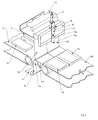
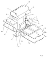
- the packaging machine is adapted to simultaneously pack two objects 5 in a film.
- the packaging machine comprises a first film web 1 and a second film web 2.
- the packaging machine further comprises a conveyor with a first conveyor belt 6a, which feeds the articles 5 in the direction of the arrow A, and a second conveyor belt 6b, which moves the packed articles in the direction of the Discharges arrow B.
- the packaged objects are identified by the reference numeral 5 '.
- the first film web 1 is arranged below the conveyor and the second film web 2 is arranged above the conveyor.
- the film webs are wound up on large rollers, which are not shown in the figures due to a better clarity.
- the first film web 1 is fed via a deflection roller 15 and a roller 4 to a film welding region of the packaging machine.
- the second film web 2 is also fed via a deflection roller 16 to the welding area of the packaging machine.
- the film webs are deflected at the deflection rollers 15, 16 and the roller 4 by approximately 90 °.
- the packaging machine further comprises a first sealing bar 8 and a second sealing bar 9, which form the welding area.
- the two welding bars 8, 9 have the same thickness and width and serve to provide heat, for which purpose the two welding bars 8, 9 have heating wires, for example.
- the packaging machine further comprises a first and a second cutting device.
- the first cutting device cuts the first film web 1 into a first film region 1a and a second film region 1b.
- the first cutting device is hidden in the figures by the first conveyor belt 6a.
- the first cutting device comprises a knife which, in the region of the deflection roller 15, divides the first film web into the two film regions 1a, 1b.
- the second cutting device is arranged on the second film web 2 and comprises a knife 14 and a pneumatic cylinder 13. By means of the pneumatic cylinder 13, the knife 14 can be pushed back and forth.
- the second cutter cuts the second film web 2 into a first film region 2a and a second film region 2b. As can be seen in particular from FIG.
- the film regions 1a, 2a, 1b, 2b of the first and second film webs 1, 2 are each the same width.
- the two film webs 1, 2 subdivided into two film areas are brought together and guided between the first and second welding bars 8, 9. This results in a vertical film curtain, to which the two objects 5 are fed by the conveyor belt.
- the second cutting unit cuts in the region of a roller 3, which is the deflection roller 16 downstream.
- the blades of the first and second cutting device can thereby cut against the rollers themselves or in the rollers, a groove is provided, in which protrudes the tip of the blade.
- the separator 10 includes a slider 11 having a wedge-shaped tip 11a and a pneumatic cylinder 12 for moving the slider 11 in the vertical direction.
- Fig. 2 shows a state of the separator 10, in which the slide 11 is advanced with the pneumatic cylinder down is so that it protrudes over the direction of the second heating beam directed heating surface of the first welding bar 8.
- the separation device 10 has the task of ensuring the simultaneous welding of the cut film webs to each other that not the first film portions 1a, 2a, which are to package a first article 5, and the second film portions 1b, 2b, which are to package a second article 5, with each other be welded.
- the tip 11a of the slider 11 penetrates between the two film portions, thus preventing the adjacent edges of the film portions from being welded together during the welding of the films.
- the function of the packaging machine according to the invention is as follows:
- the articles 5 to be packaged are fed simultaneously by the first conveyor belt 6a for packaging.
- the articles 5 are thereby fed into a vertical film curtain formed by the first film web 1 and the second film web 2.
- the first and second welding bars 8, 9 are located in the position shown in FIG. 2, so that the objects 5 run in the film curtain and are guided under the first welding bar 8.
- the two objects 5 are simultaneously covered both from above and from below with foil.
- the first film web 1 During the feeding of the first film web 1, it is subdivided into a first film region 1a and a second film region 1b by means of a cutting device (not shown).
- the two film areas 1a, 1b are the same size, since the same objects 5 are to be packaged.
- the second film web 2 by a knife 14 of a second cutting device in a divided first film area 2a and a second film area 2b.
- Each of the two objects 5 thereby runs in a film curtain formed by the film regions 1a, 2a or 1b, 2b.
- the first welding bar 8 When the articles 5 to be packaged are completely under the first welding bar 8, it is moved vertically downward to the position shown in FIG. 3 to carry out the welding operation of the first and second film webs 1, 2 with each other.
- the first sealing bar 8 is pressed against the second sealing bar 9 and the heat present on the sealing bars 8, 9 welds the foil webs together.
- the second welding bar is arranged stationary, but may alternatively also be movable in the vertical direction.
- the separating device 10 is provided in order to prevent the film regions 1a, 2a from being welded to the film regions 1b, 2b at the longitudinal edges.
- the separating device 10 is provided in order to prevent the film regions 1a, 2a from being welded to the film regions 1b, 2b at the longitudinal edges.
- the separating device 10 is provided in order to prevent the film regions 1a, 2a from being welded to the film regions 1b, 2b at the longitudinal edges.
- the slider 11 of the separator 10 projects beyond the vertically lower end of the first welding bar
- the tip 11a of the slider 11 is guided between the two longitudinal edges of the cut film regions and separates the film regions from one another. This prevents the foil areas from being welded together in their longitudinal direction during the welding process.
- each article 5 ' can be completely packaged.
- the separating device 10 is lifted together with the first welding bar 8 again. As a result, the slider 11 is pulled out between the two film web areas. However, because the film temperature drops immediately in the area of the weld, there is no longer any danger that they could unintentionally connect.
- two weld seams are simultaneously formed during the welding process, namely welding of the articles 5 'and welding of the film region 1a to the film region 2a and the film region 1b to the film region 2b for the packaging of the next articles.
- the vertical film curtain is thus simultaneously formed again, in which the subsequently conveyed objects 5 are supplied.
- a further cutting device is preferably provided in the region of the welding bars 8, 9.
- two articles 5 can thus be simultaneously packed, the packaging machine having a very compact and simple construction.
- the packaging machine according to the invention can also be converted in a simple way for the packaging of individual objects by the slider 11 is moved by the pneumatic cylinder 12 upwards, so that the tip 11a of the slider no longer protrudes beyond the lower heating surface of the first welding bar 8.
- the first and second cutters are also retracted, so that a single article with a relatively large width can be packed.
- the changeover times are only in seconds, since only the pneumatic cylinder must be operated.
- the slider 11 has a slot 11b in which a guide element 17 in the form of a pin protrudes.
- the pin is thereby fixed to the first welding bar 8 and can also serve as a stop for limiting movement of the slider in the vertical direction.
Landscapes
- Engineering & Computer Science (AREA)
- Mechanical Engineering (AREA)
- Containers And Plastic Fillers For Packaging (AREA)
- Basic Packing Technique (AREA)
- Lining Or Joining Of Plastics Or The Like (AREA)
Applications Claiming Priority (1)
| Application Number | Priority Date | Filing Date | Title |
|---|---|---|---|
| DE200610021599 DE102006021599B3 (de) | 2006-05-09 | 2006-05-09 | Vorrichtung zum gleichzeitigen Verpacken von Gegenständen |
Publications (3)
| Publication Number | Publication Date |
|---|---|
| EP1857366A2 true EP1857366A2 (fr) | 2007-11-21 |
| EP1857366A3 EP1857366A3 (fr) | 2008-07-02 |
| EP1857366B1 EP1857366B1 (fr) | 2010-08-11 |
Family
ID=38291208
Family Applications (1)
| Application Number | Title | Priority Date | Filing Date |
|---|---|---|---|
| EP20070009071 Not-in-force EP1857366B1 (fr) | 2006-05-09 | 2007-05-04 | Dispositif d'emballage simultané d'objets |
Country Status (3)
| Country | Link |
|---|---|
| EP (1) | EP1857366B1 (fr) |
| DE (1) | DE102006021599B3 (fr) |
| ES (1) | ES2349735T3 (fr) |
Citations (5)
| Publication number | Priority date | Publication date | Assignee | Title |
|---|---|---|---|---|
| DE517130C (de) * | 1929-04-30 | 1931-01-31 | Saechsische Cartonnagen Maschi | Vorrichtung zum Auseinanderfuehren der Einzelstreifen laengszerteilter Rollenkartonsfuer Schachtelherstellungsmaschinen |
| US2673430A (en) * | 1949-06-18 | 1954-03-30 | Crystal Tissue Company | Wrapping and packaging machine |
| GB884195A (en) * | 1957-02-14 | 1961-12-06 | Joa Curt G | Method of and apparatus for forming and covering fibrous pads |
| US4466228A (en) * | 1981-11-12 | 1984-08-21 | L. C. Gess, Inc. | Method and apparatus for producing packages from cohesive-coated media |
| EP0129512A2 (fr) * | 1983-06-20 | 1984-12-27 | SIG Schweizerische Industrie-Gesellschaft | Dispositif dans une machine d'emballage pour la fabrication de sacs d'emballage |
-
2006
- 2006-05-09 DE DE200610021599 patent/DE102006021599B3/de not_active Expired - Fee Related
-
2007
- 2007-05-04 ES ES07009071T patent/ES2349735T3/es active Active
- 2007-05-04 EP EP20070009071 patent/EP1857366B1/fr not_active Not-in-force
Patent Citations (5)
| Publication number | Priority date | Publication date | Assignee | Title |
|---|---|---|---|---|
| DE517130C (de) * | 1929-04-30 | 1931-01-31 | Saechsische Cartonnagen Maschi | Vorrichtung zum Auseinanderfuehren der Einzelstreifen laengszerteilter Rollenkartonsfuer Schachtelherstellungsmaschinen |
| US2673430A (en) * | 1949-06-18 | 1954-03-30 | Crystal Tissue Company | Wrapping and packaging machine |
| GB884195A (en) * | 1957-02-14 | 1961-12-06 | Joa Curt G | Method of and apparatus for forming and covering fibrous pads |
| US4466228A (en) * | 1981-11-12 | 1984-08-21 | L. C. Gess, Inc. | Method and apparatus for producing packages from cohesive-coated media |
| EP0129512A2 (fr) * | 1983-06-20 | 1984-12-27 | SIG Schweizerische Industrie-Gesellschaft | Dispositif dans une machine d'emballage pour la fabrication de sacs d'emballage |
Also Published As
| Publication number | Publication date |
|---|---|
| DE102006021599B3 (de) | 2007-10-11 |
| EP1857366A3 (fr) | 2008-07-02 |
| EP1857366B1 (fr) | 2010-08-11 |
| ES2349735T3 (es) | 2011-01-11 |
Similar Documents
| Publication | Publication Date | Title |
|---|---|---|
| DE3213561C2 (fr) | ||
| DE2534306C2 (de) | Verfahren und Vorrichtung zur Herstellung von Beuteln mit einer Bodenfalte | |
| DE4026807C2 (fr) | ||
| WO2002026589A1 (fr) | Corps de remplissage remplis de gaz | |
| EP2858798B1 (fr) | Dispositif et procédé de décorticage et de séparation de découpes | |
| DE19913408A1 (de) | Gasgefüllte Füllkörper | |
| DE2832365B2 (de) | Vorrichtung zum Fördern und Vereinzeln eines Bandes aus zusammenhängenden Skin-Verpackungen | |
| DE102012202016A1 (de) | Verfahren und Vorrichtung zur Konfektionierung von dünnen Kunststofffolien | |
| DE69118048T2 (de) | Vorrichtung und Verfahren zum Herstellen, Befüllen und Siegeln bei gleichzeitigem Verpacken von zwei Artikelströmen | |
| EP0482435A2 (fr) | Procédé et dispositif pour la détermination de la position d'un élément pour marquer ou séparer dans une pile des articles plans | |
| DE102014101802B4 (de) | Verfahren und Vorrichtung zum Ultraschall-Siegeln und Trennen von Schlauchbeuteln | |
| EP2332843B1 (fr) | Dispositif de soudage de séparation longitudinale pour une machine d'emballage de feuilles | |
| DE102009060342A1 (de) | Verpackungsmaschine mit überbrückter Stempellücke und Verfahren | |
| EP1857366B1 (fr) | Dispositif d'emballage simultané d'objets | |
| DE102012103352B4 (de) | Verpackungsmaschine mit mitlaufender Quertrennschweißeinrichtung | |
| DE1816108C3 (de) | Verfahren und Vorrichtung zum gleichzeitigen Herstellen von mehreren, dem Verpacken dienenden Verbundstreifen | |
| DE3539986C2 (fr) | ||
| EP1925557B1 (fr) | Station rotative et de décalaminage pour articles d'emballages de taille variable et machine d'emballage de feuilles pour articles d'emballage de taille variable | |
| EP2093048B1 (fr) | Dispositif destiné à la fabrication d'une protection des rebords | |
| EP3967637B1 (fr) | Dispositif et procédé d'épissurage et de fourniture continue d'une bande continue de feuille | |
| DE102018102369B4 (de) | Folienverpackungsmaschine zum Verpacken von Gegenständen in Luftpolsterfolienverpackungen | |
| EP1988043B1 (fr) | Procédé et appareil pour le prépliage d'une bande | |
| DE69224425T2 (de) | Verfahren und Vorrichtung zum Zuführen von Verpackungsmaterial an einer Verpackungsmaschine | |
| EP2364914A2 (fr) | Poinçon inférieur réglable en largeur | |
| DE2116747B2 (de) | Verfahren und Vorrichtung zum Herstellen H-förmiger Perforationsschnitte in einer Pack Stoffbahn |
Legal Events
| Date | Code | Title | Description |
|---|---|---|---|
| PUAI | Public reference made under article 153(3) epc to a published international application that has entered the european phase |
Free format text: ORIGINAL CODE: 0009012 |
|
| AK | Designated contracting states |
Kind code of ref document: A2 Designated state(s): AT BE BG CH CY CZ DE DK EE ES FI FR GB GR HU IE IS IT LI LT LU LV MC MT NL PL PT RO SE SI SK TR |
|
| AX | Request for extension of the european patent |
Extension state: AL BA HR MK YU |
|
| PUAL | Search report despatched |
Free format text: ORIGINAL CODE: 0009013 |
|
| AK | Designated contracting states |
Kind code of ref document: A3 Designated state(s): AT BE BG CH CY CZ DE DK EE ES FI FR GB GR HU IE IS IT LI LT LU LV MC MT NL PL PT RO SE SI SK TR |
|
| AX | Request for extension of the european patent |
Extension state: AL BA HR MK RS |
|
| 17P | Request for examination filed |
Effective date: 20080917 |
|
| AKX | Designation fees paid |
Designated state(s): ES IT |
|
| REG | Reference to a national code |
Ref country code: DE Ref legal event code: 8566 |
|
| GRAP | Despatch of communication of intention to grant a patent |
Free format text: ORIGINAL CODE: EPIDOSNIGR1 |
|
| GRAS | Grant fee paid |
Free format text: ORIGINAL CODE: EPIDOSNIGR3 |
|
| GRAA | (expected) grant |
Free format text: ORIGINAL CODE: 0009210 |
|
| AK | Designated contracting states |
Kind code of ref document: B1 Designated state(s): ES IT |
|
| REG | Reference to a national code |
Ref country code: ES Ref legal event code: FG2A Effective date: 20101228 |
|
| PLBE | No opposition filed within time limit |
Free format text: ORIGINAL CODE: 0009261 |
|
| STAA | Information on the status of an ep patent application or granted ep patent |
Free format text: STATUS: NO OPPOSITION FILED WITHIN TIME LIMIT |
|
| 26N | No opposition filed |
Effective date: 20110512 |
|
| PGFP | Annual fee paid to national office [announced via postgrant information from national office to epo] |
Ref country code: IT Payment date: 20140526 Year of fee payment: 8 Ref country code: ES Payment date: 20140521 Year of fee payment: 8 |
|
| PG25 | Lapsed in a contracting state [announced via postgrant information from national office to epo] |
Ref country code: IT Free format text: LAPSE BECAUSE OF NON-PAYMENT OF DUE FEES Effective date: 20150504 |
|
| PG25 | Lapsed in a contracting state [announced via postgrant information from national office to epo] |
Ref country code: ES Free format text: LAPSE BECAUSE OF NON-PAYMENT OF DUE FEES Effective date: 20150505 |
|
| REG | Reference to a national code |
Ref country code: ES Ref legal event code: FD2A Effective date: 20180629 |