EP1855876B2 - Prägerolle, prägevorrichtung mit der rolle - Google Patents
Prägerolle, prägevorrichtung mit der rolle Download PDFInfo
- Publication number
- EP1855876B2 EP1855876B2 EP06711441.3A EP06711441A EP1855876B2 EP 1855876 B2 EP1855876 B2 EP 1855876B2 EP 06711441 A EP06711441 A EP 06711441A EP 1855876 B2 EP1855876 B2 EP 1855876B2
- Authority
- EP
- European Patent Office
- Prior art keywords
- roller
- embossing
- pattern
- protuberances
- bands
- Prior art date
- Legal status (The legal status is an assumption and is not a legal conclusion. Google has not performed a legal analysis and makes no representation as to the accuracy of the status listed.)
- Active
Links
Images


Classifications
-
- B—PERFORMING OPERATIONS; TRANSPORTING
- B31—MAKING ARTICLES OF PAPER, CARDBOARD OR MATERIAL WORKED IN A MANNER ANALOGOUS TO PAPER; WORKING PAPER, CARDBOARD OR MATERIAL WORKED IN A MANNER ANALOGOUS TO PAPER
- B31F—MECHANICAL WORKING OR DEFORMATION OF PAPER, CARDBOARD OR MATERIAL WORKED IN A MANNER ANALOGOUS TO PAPER
- B31F1/00—Mechanical deformation without removing material, e.g. in combination with laminating
- B31F1/07—Embossing, i.e. producing impressions formed by locally deep-drawing, e.g. using rolls provided with complementary profiles
-
- B—PERFORMING OPERATIONS; TRANSPORTING
- B31—MAKING ARTICLES OF PAPER, CARDBOARD OR MATERIAL WORKED IN A MANNER ANALOGOUS TO PAPER; WORKING PAPER, CARDBOARD OR MATERIAL WORKED IN A MANNER ANALOGOUS TO PAPER
- B31F—MECHANICAL WORKING OR DEFORMATION OF PAPER, CARDBOARD OR MATERIAL WORKED IN A MANNER ANALOGOUS TO PAPER
- B31F2201/00—Mechanical deformation of paper or cardboard without removing material
- B31F2201/07—Embossing
- B31F2201/0707—Embossing by tools working continuously
- B31F2201/0715—The tools being rollers
- B31F2201/0723—Characteristics of the rollers
- B31F2201/0733—Pattern
-
- B—PERFORMING OPERATIONS; TRANSPORTING
- B31—MAKING ARTICLES OF PAPER, CARDBOARD OR MATERIAL WORKED IN A MANNER ANALOGOUS TO PAPER; WORKING PAPER, CARDBOARD OR MATERIAL WORKED IN A MANNER ANALOGOUS TO PAPER
- B31F—MECHANICAL WORKING OR DEFORMATION OF PAPER, CARDBOARD OR MATERIAL WORKED IN A MANNER ANALOGOUS TO PAPER
- B31F2201/00—Mechanical deformation of paper or cardboard without removing material
- B31F2201/07—Embossing
- B31F2201/0758—Characteristics of the embossed product
- B31F2201/0761—Multi-layered
-
- B—PERFORMING OPERATIONS; TRANSPORTING
- B31—MAKING ARTICLES OF PAPER, CARDBOARD OR MATERIAL WORKED IN A MANNER ANALOGOUS TO PAPER; WORKING PAPER, CARDBOARD OR MATERIAL WORKED IN A MANNER ANALOGOUS TO PAPER
- B31F—MECHANICAL WORKING OR DEFORMATION OF PAPER, CARDBOARD OR MATERIAL WORKED IN A MANNER ANALOGOUS TO PAPER
- B31F2201/00—Mechanical deformation of paper or cardboard without removing material
- B31F2201/07—Embossing
- B31F2201/0784—Auxiliary operations
- B31F2201/0794—Cutting
-
- Y—GENERAL TAGGING OF NEW TECHNOLOGICAL DEVELOPMENTS; GENERAL TAGGING OF CROSS-SECTIONAL TECHNOLOGIES SPANNING OVER SEVERAL SECTIONS OF THE IPC; TECHNICAL SUBJECTS COVERED BY FORMER USPC CROSS-REFERENCE ART COLLECTIONS [XRACs] AND DIGESTS
- Y10—TECHNICAL SUBJECTS COVERED BY FORMER USPC
- Y10T—TECHNICAL SUBJECTS COVERED BY FORMER US CLASSIFICATION
- Y10T156/00—Adhesive bonding and miscellaneous chemical manufacture
- Y10T156/12—Surface bonding means and/or assembly means with cutting, punching, piercing, severing or tearing
- Y10T156/1304—Means making hole or aperture in part to be laminated
-
- Y—GENERAL TAGGING OF NEW TECHNOLOGICAL DEVELOPMENTS; GENERAL TAGGING OF CROSS-SECTIONAL TECHNOLOGIES SPANNING OVER SEVERAL SECTIONS OF THE IPC; TECHNICAL SUBJECTS COVERED BY FORMER USPC CROSS-REFERENCE ART COLLECTIONS [XRACs] AND DIGESTS
- Y10—TECHNICAL SUBJECTS COVERED BY FORMER USPC
- Y10T—TECHNICAL SUBJECTS COVERED BY FORMER US CLASSIFICATION
- Y10T156/00—Adhesive bonding and miscellaneous chemical manufacture
- Y10T156/15—Combined or convertible surface bonding means and/or assembly means
-
- Y—GENERAL TAGGING OF NEW TECHNOLOGICAL DEVELOPMENTS; GENERAL TAGGING OF CROSS-SECTIONAL TECHNOLOGIES SPANNING OVER SEVERAL SECTIONS OF THE IPC; TECHNICAL SUBJECTS COVERED BY FORMER USPC CROSS-REFERENCE ART COLLECTIONS [XRACs] AND DIGESTS
- Y10—TECHNICAL SUBJECTS COVERED BY FORMER USPC
- Y10T—TECHNICAL SUBJECTS COVERED BY FORMER US CLASSIFICATION
- Y10T428/00—Stock material or miscellaneous articles
- Y10T428/15—Sheet, web, or layer weakened to permit separation through thickness
-
- Y—GENERAL TAGGING OF NEW TECHNOLOGICAL DEVELOPMENTS; GENERAL TAGGING OF CROSS-SECTIONAL TECHNOLOGIES SPANNING OVER SEVERAL SECTIONS OF THE IPC; TECHNICAL SUBJECTS COVERED BY FORMER USPC CROSS-REFERENCE ART COLLECTIONS [XRACs] AND DIGESTS
- Y10—TECHNICAL SUBJECTS COVERED BY FORMER USPC
- Y10T—TECHNICAL SUBJECTS COVERED BY FORMER US CLASSIFICATION
- Y10T428/00—Stock material or miscellaneous articles
- Y10T428/24—Structurally defined web or sheet [e.g., overall dimension, etc.]
- Y10T428/24479—Structurally defined web or sheet [e.g., overall dimension, etc.] including variation in thickness
- Y10T428/24612—Composite web or sheet
-
- Y—GENERAL TAGGING OF NEW TECHNOLOGICAL DEVELOPMENTS; GENERAL TAGGING OF CROSS-SECTIONAL TECHNOLOGIES SPANNING OVER SEVERAL SECTIONS OF THE IPC; TECHNICAL SUBJECTS COVERED BY FORMER USPC CROSS-REFERENCE ART COLLECTIONS [XRACs] AND DIGESTS
- Y10—TECHNICAL SUBJECTS COVERED BY FORMER USPC
- Y10T—TECHNICAL SUBJECTS COVERED BY FORMER US CLASSIFICATION
- Y10T428/00—Stock material or miscellaneous articles
- Y10T428/24—Structurally defined web or sheet [e.g., overall dimension, etc.]
- Y10T428/24802—Discontinuous or differential coating, impregnation or bond [e.g., artwork, printing, retouched photograph, etc.]
- Y10T428/24934—Discontinuous or differential coating, impregnation or bond [e.g., artwork, printing, retouched photograph, etc.] including paper layer
Definitions
- the present invention relates to innovations to devices for embossing web materials, and especially webs or sheets of paper, in particular tissue paper, to produce rolls of toilet paper, kitchen towels, paper napkins or similar products.
- the invention relates to improvements concerning the configuration of the embossing rollers.
- one or more plies of paper are usually subjected to an embossing operation, with which the paper material is permanently deformed to form thereon protuberances of various shapes.
- embossing which also causes localized breakage of the cellulose fibers forming the paper web, has a technical-function object, consisting in increasing the softness and volume of the finished product, together with its absorption capacity.
- embossing is also used to define limited areas, at the level of which a glue is applied to join together two or more plies forming the finished multi-ply product.
- embossing also has the object of providing the product with a pleasing aesthetic appearance, and in some cases also of characterizing the product of a specific manufacturer.
- embossing patterns currently used must in the first place be compatible with the technical and functional requirements of the product but also of the machine that converts the material. This poses serious limits to the type of decoration obtainable with embossing.
- the embossing pattern must take account of the fact that the glue, which guarantees joining of the plies, is applied to the protuberances obtained by deforming the material. As the plies must also be joined reliably along the cutting edges, the embossed patterns cannot be centered with respect to the finished product, leaving the perimeter areas free. Rather, they must extend right to the edges.
- embossing is generally obtained by pressing a pressure roller coated in an resiliently yielding material against an embossing roller, generally made of steel or another rigid material, provided with embossing protuberances, and by feeding the material to be embossed into the nip between the two rollers.
- the rollers rotate at high speed.
- the embossing protuberances on the embossing rollers generate strong vibrations.
- the embossing pattern in particular the distribution and dimension of the protuberances, has a considerable influence on dynamic phenomena in machines, to the extent that some embossing patterns are totally incompatible with correct operation of the embossing unit and of the entire line at the production speeds compatible with the current needs for high productivity.
- the most critical phenomenon determined by the embossing protuberances is represented by the generation of vibrations in the machine caused by sudden variation of the contact surface between embossing roller and pressure roller, due to the fact that this contact surface is defined by the embossing protuberances, and consequently varies cyclically as the rollers rotate.
- EP 0,370,972 describes a specific arrangement of the protuberances of the embossing roller, which guarantees high operational constancy while reducing vibrations to a minimum.
- EP 0,370,972 describes an embossing device in which the tips are aligned according to multi-start helices. In the case of complex embossing patterns especially, according to this method it is particularly critical to calculate the pitch and inclination of the helices so that these are completed on the diameter of the embossing roller.
- more complex arrangements of protuberances are also used, with background protuberances of small dimensions and high density, e.g. frusto-pyramid or frusto-conical protuberances, arranged according to helical alignments, with which protuberances or groups of protuberances forming decorations of larger dimension are combined. These decorations are again arranged in helical alignments, so that contact between the embossing roller and the pressure roller is always gradual and uniform.
- the embossed patterns are always arranged according to alignments inclined with respect to the edges of the paper and are usually of small dimensions.
- an embossing roller according to claim 1 is provided, which allows embossed products of high quality and aesthetic prestige to be obtained, without difficulties in the production phase.
- annular and longitudinal bands in combination with the principal intermediate embossed pattern in each square defined by the intersection of the annular and longitudinal bands allows the embossing protuberances to be arranged so as to obtain substantially continuous and uniform contact between the embossing roller and the pressure roller.
- This principle of distribution of the embossing patterns in fact allows a noteworthy number of protuberances along any generatrix of the roller, so as to reduce the generation of vibrations caused by variation of the contact surface of the embossing roller with a corresponding pressure roller.
- the longitudinal bands are parallel to the axis of the roller. Regularity of the contact between embossing roller and pressure roller is in any case guaranteed by the presence of the protuberances along the annular bands and of the protuberances defining the principal pattern.
- the longitudinal bands can advantageously be inclined with respect to the axis of the roller. In this case it is advantageous for the principal embossing patterns to be offset from one another, i.e. for the patterns arranged along an annular alignment to be offset with respect to those of the adjacent alignment. The inclination can be small, i.e.
- the longitudinal bands are preferably inclined with a single or multiple V-shape. This arrangement has a guiding effect on the ply and can also have a widening effect.
- the invention also relates to an embossing unit according to claim 12 comprising an embossing roller of the aforesaid type and a production line according to claim 13 for producing rolls of toilet tissue, kitchen towels or the like, with an embossing unit equipped with an embossing roller of the aforesaid type.
- Figure 1 schematically shows a portion of a line for converting tissue paper and producing rolls of toilet paper or kitchen towels.
- the line comprises an unwinder 1, in which two reels B1 and B2 of large diameter are unwound to feed the line.
- the plies fed from the reels B1 and B2 are indicated with V1 and V2.
- auxiliary embossing units 3 and 5 Arranged along the feed path of the plies V1 and V2 are respective auxiliary embossing units 3 and 5, each of which can, for example, have a steel embossing roller and a pressure roller cooperating therewith.
- the auxiliary embossing units 3 and 5 can be designed conventionally and provided to impress background embossing on the two plies V1 and V2, for example micro-embossing composed of a fine geometrical pattern formed of truncated-pyramid shaped protuberances or the like.
- a pattern of this type can have a density of at least 10 protuberances/cm 2 or preferably of at least 15 protuberances/cm 2 and preferably between 30 and 90 protuberances/cm 2 .
- Each reel B1, B2 and therefore each ply V1 and V2 can in turn be composed of one, two or more layers.
- the reels B1 and B2 can also be replaced by a single two-ply reel.
- an embossing and laminating unit 7 Arranged downstream of the auxiliary embossing units 3 and 5 is an embossing and laminating unit 7, the configuration of which is shown in greater detail in Figure 2 and will be described hereunder.
- the two plies V1 and V2 Upon delivery from the embossing and laminating unit 7 the two plies V1 and V2 form a single web article N, which is fed to a rewinding machine 9, of a type known per se and not described in greater detail.
- a perforator 8 Associated with the rewinding machine 9 is a perforator 8 which makes, on the web material N, transverse perforation lines, equidistant from one another and substantially orthogonal to the direction of longitudinal feed of the web material N.
- the rewinding machine 9 produces logs L of a diameter equivalent to the diameter of the finished rolls and a length equal to a multiple of the axial length of the rolls.
- the logs are accumulated in an intermediate storage unit or store 11 and from here are sent to one or more cutting machines 13 that divide the logs L into rolls R.
- the structure of the cutting machine is also known per se and will not be described herein.
- the embossing and laminating unit 7 includes an embossing roller 21 provided on the cylindrical surface thereof with protuberances, indicated here generically with P, the arrangement of which forms a specific object of the present invention and will be described in greater detail hereunder.
- a pressure roller 23 Cooperating with the embossing roller 21 is a pressure roller 23, the outer surface of which is defined by a layer 23A of resiliently yielding material, such as rubber.
- the pressure roller 23 and the embossing roller 21 are pressed against each other at high pressure, so that the protuberances P of the embossing roller 21 penetrate the smooth surface of the coating 23A of the roller 23 to deform it.
- the ply V1 is fed around the pressure roller 23 and into the embossing nip defined between the pressure roller 23 and the embossing roller 21, so as to be embossed with a pattern corresponding to the arrangement of the protuberances P.
- a glue dispensing unit 25 Arranged downstream of the embossing nip along the embossing roller 21 is a glue dispensing unit 25, with an applicator cylinder 25A, which applies a glue to the raised surfaces of the embossed ply V1, at the level of all or of some of the protuberances of the roller 21.
- the ply V1 remains engaged with the cylindrical surface of the embossing roller 21 until it is downstream of a lamination nip defined by the embossing roller 21 and a lamination roller 27, which can be coated with a resiliently yielding material, preferably of greater hardness than the coating of the roller 23.
- the ply V2 is also fed into the lamination nip and is glued to the ply V1 at the level of the areas wet with glue.
- the web material N formed of the two plies joined together is delivered downstream of the lamination nip.
- Figure 3 schematically shows an axonometric view of the embossing roller 21, the cylindrical surface of which is indicated with 21 S.
- 21 S defined on the surface 21S of the roller 21 are annular i.e. circumferential areas or bands 21C, along which protuberances are arranged to define an embossing pattern, which will be referred to hereunder as circumferential secondary embossing pattern.
- the enlargement in Figure 3A shows a possible conformation of this pattern.
- a longitudinal band 21 L is also represented on the cylindrical surface 21S of the embossing roller 21.
- several longitudinal bands 21L are provided along the circular extension of the roller 21, all having substantially the same development and not visible in the axonometric view in Figure 3 .
- each longitudinal band 21 L has a substantially V-shape with a very wide angle at the vertex. With the direction of rotation of the roller indicated by the arrow F in Figure 3 , this V-shaped arrangement of the protuberances defining the bands 21 L has a transverse widening effect on the embossed material.
- protuberances defining an embossing pattern which will be referred to hereinafter as longitudinal secondary embossing pattern, are also provided along the longitudinal bands 21 L.
- Figure 3B shows a greatly enlarged view of an example of a pattern of this type.
- the pattern is formed of elongated protuberances P11 and of pointed protuberances P21.
- the protuberances are arranged so as to form variously inclined alignments with respect to a generatrix G, i.e. a straight line parallel to the axis A-A of the roller 21.
- the opposite inclination of the two portions into which each longitudinal band L is divided, and the width of said band are such that the generatrix G is contained fully in the width of the band 21 L.
- the generatrix G coincides with a perforation line generated on said material.
- the bands 21C and 21L define on the cylindrical surface 21S of the embossing roller 21 a series of squares Q, with more or less the same dimensions, inside each of which a raised pattern, generically indicated with D and hereinafter referred to as principal embossing pattern, is produced.
- the longitudinal and inclined bands 21 L can be formed by portions of band parallel to the axis A-A of the roller 21, at the level of each square Q, with the portions of subsequent squares offset from one another to obtain an overall V-shaped arrangement as described above. In this way, portions of band 21 L parallel to the generatrix of the roller are obtained between two annular bands 21C.
- This arrangement is indicated schematically in Figure 3 .
- rolls of web material are obtained, formed by a series of sheets separated by perforation lines included inside the embossed pattern generated by the protuberances arranged within the longitudinal bands 21 L. In each sheet the portion of embossing in which the perforation line is contained is parallel to said perforation line.
- Each principal embossed pattern D is formed by a series of protuberances varying in shape and dimension, arranged to form the decorative motif forming the pattern D.
- the various patterns D of the squares Q can be the same as or different from one another. As will be described with reference to specific embodiments, in each annular row of squares Q defined between two consecutive annular bands 21C, the patterns can be all the same, all different, or of two or three types alternated with one another along the extension of the annular alignment of squares Q. Moreover, some squares can be devoid of decoration D.
- the alignments of squares Q defined between adjacent annular or circumferential bands 21C can have the same or different patterns, with the same sequence in phase or with the same sequence but out of phase, as will be apparent hereunder.
- a web product N is obtained with a width equal to a multiple of the axial length of the rolls R to be produced.
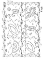
- Figure 5 shows a portion of a web article N thus obtained with a possible example of embossed pattern, viewed from the exposed face of the ply V1. On the opposite face the pattern is less visible, as the lamination roller 27 does not emboss or only limitedly embosses the plies V1 and V2 during lamination. Naturally, it would also be possible to markedly emboss the web material N in the lamination nip as well.
- the embossing roller has generated a series of bands F1, F2, F3 and F4 of decorations composed of principal embossed patterns D.
- five principal embossed patterns D respectively representing (from bottom to top) a drinking glass, a beach umbrella, a snor-keling mask, a yacht, a slice of watermelon, are arranged in sequence in the band F1.
- the patterns are, obviously, to be considered as examples, it being understood that the specific appearance of these patterns is not limiting.
- the same motifs are reproduced in the band F2, offset by one step, i.e.
- the motif in the lower position in this case being a life buoy, which is also present in the top portion of the band F1, not represented.
- the same patterns as the band F1 are again reproduced, offset by two steps, i.e. by two squares, with the bottom square containing the pattern of the slice of watermelon and the second square from the bottom representing the life buoy.
- the band F4 represents the same patterns or motifs offset by a further step or square.
- the bands F1-F4 are separated from one another by longitudinal secondary embossed patterns indicated with V, formed by the protuberances of the annular or circumferential bands 21C on the surface of the roller 21.
- V longitudinal secondary embossed patterns
- the lines L1 therefore represent the edges of the material that will form the individual rolls into which the material N will be cut by the cutting machine 13.
- the width of the longitudinal secondary embossed patterns, corresponding to the width of the circumferential bands 21C of the roller 21, is such that the cutting line L1 falls inside the band even in the case of an error in positioning-the logs L during cutting in the cutting machine 13.
- the configuration of the longitudinal secondary embossed pattern is such that the final user of the product does not perceive any slight offset between the line L1 and the band of the longitudinal embossed pattern, as the longitudinal secondary embossed pattern has no median line of symmetry or, in any case, a symmetry to be complied with.
- the lines L2 represent the perforation lines, orthogonal to the lines L1. These perforation lines L2 are generated by the perforator 8. on the web material N and are in phase with the bands of a transverse secondary embossed pattern, generated by the bands of longitudinal protuberances 21 L.
- the secondary embossed pattern along the lines L2, indicated with U, is only partly shown for simplicity of the drawing, but it must be understood that this pattern is produced along all the perforation lines L2.
- Figure 5A shows enlargements of two areas A and B in Figure 5 , reproduced side by side.
- the perforation line L2 is not parallel to the band of the transverse secondary embossed pattern, as the longitudinal bands 21 L of protuberances that generate this secondary embossing are not parallel to the generatrix of -the embossing roller 21, but are formed by single segments each paraiiei with the axis of the roller, but offset from one another to obtain an overall V-shaped arrangement.
- the configuration of the protuberances P21, P11 which form the embossings of the transverse secondary embossed patterns is such that reciprocal offset between the embossed bands and the perforation line L2 is not perceived by the person observing the pattern of the finished product, the width of which is equal to the width of only one of the bands F1-F4.
- the object of the overall inclination of the longitudinal bands 21 L is to increase uniformity of contact between the embossing roller 21 and the pressure roller 23.
- the principal embossed patterns D are formed, as mentioned, by protuberances of various shape and dimension, compatible with the requirements of correct bonding and correct deformation of the cellulose material.
- the dimension of the individual principal embossed patterns is such that the pattern substantially occupies the entire square, coming close to the edge areas.
- the number of protuberances intersected by the line varies, although to a relatively small extent, thanks to the dimension of the principal embossed patterns D in the squares Q, which occupy a high surface area of the respective squares, to the alternation of the patterns D which are out of phase in the individual bands, to the presence of the longitudinal secondary embossed patterns along the lines L1, and also to the inclination of the transverse secondary embossed patterns with respect to the lines L2.
- the ideal straight line (geometrical line) LL which runs on the final web product N represents the ideal contact line between the rollers 21 and 23 during rotation thereof. Consequently, along this contact line there are always a large number of protuberances of the embossing roller 21 which penetrate the coating of the pressure roller 23, deforming it. This effect is obtained without a helical pattern being produced on the embossing roller 21, and without a repetitive motif with a helical trend being visible on the finished product.
- the rolls obtained by longitudinal cutting along the lines L1 are characterized by individual sheets, each defined by two transverse perforation lines L2; each of which is decorated with a single wide principal embossed pattern D surrounded by a frame formed of longitudinal and transverse secondary embossed patterns.
- Figure 4 schematically shows three partially unwound rolls, obtained by cutting the web material in Figure 5 .
- geometrical embossed patterns have been produced along the perforation lines L2 and along the cutting lines L1, composed of a "disorderly" distribution of elongated and pointed protuberances.
- this is not the only solution to obtain the effects of the invention.
- it is possible to produce secondary embossed patterns representing a real subject, while maintaining the technical advantages and results illustrated above.
- FIG. 6 An example of an embossed pattern of this type is shown in Figure 6 .
- This shows six squares belonging to three separate longitudinal bands of a web material N which is to be cut, once wound in a roll, along the cutting lines L1.
- the web material N is perforated along the perforation lines L2.
- the principal embossed patterns D are represented by way of example by a slice of watermelon, a life buoy, a drinking glass and a shell, combined with other signs representing waves, birds, a sun, etc.
- Secondary longitudinal embossed patterns represented by stylized flying birds, indicated with V and each formed of two elongated and undulated protuberances and one intermediate pointed protuberance, are produced along longitudinal bands containing the cutting lines L1.
- the protuberances defining these patterns intersect the lines L1 variably and not complying, for example, with a line of symmetry. Therefore, the line L1 can also be slightly offset with respect to the ideal position represented in the drawing. It remains within the band defined by the patterns V, intersecting them.
- the user of the finished product composed of a single sequence of squares Q with alternation of the various decorations D will not perceive any-offset between the secondary embossed patterns V and the longitudinal edge line of the product, represented by the cut performed along the line L1.
- the stylized birds formed by the protuberances along the lines L1 forming the motifs produced by the annular or circumferential bands of protuberances 21C form a first part of a frame which does not require to be perfectly centered (thereby guaranteeing a tolerance on the precision of the position to cut the log into rolls) and which, as in the stylized patterns of the example in Figure 4 , guarantee application of glue between the plies V1, V2 up to the very end of the longitudinal cutting line of the product.
- Transverse secondary embossed patterns formed by sequences of protuberances representing stylized shells are produced along the perforation lines L2.
- the transverse secondary embossed patterns formed by the protuberances contained in the longitudinal bands 21 L allow the plies V1 and V2 to be glued right up to the perforation line L2. This can also be offset, for example, due to inexact synchronization between the perforator 8 and the embossing unit 7, or due to the effects of elastic elongation of the paper along its path caused by possible fluctuations in tension.
- the width of the band containing the transverse secondary embossed patterns formed by the motifs U is such that the perforation line L3 falls within said band, and the patterns are such that the person using the finished product does not perceive any misalignments of the perforation lines.
- the contact and pressure areas (represented by the protuberances intersected by the line LL), remain more or less equal in number and distribute randomly and uniformly along the width of the machine, i.e. along the axial length of the rollers. This is true (in this case) even though the bands containing the lines L2 are exactly parallel to the axis A-A of the embossing roller 21.
- the presence of protuberances even along the entire width of the roller also guarantees relatively uniform wear of the rubber or other yielding coating of the pressure roller, as there are no annular lines devoid of protuberances.
- Figure 7 shows a portion of a web material with a different embossed pattern produced following the same principle.
- the same numbers indicate parts, which are the same as or equivalent to those in Figure 5 .
- the cutting lines L1 which will separate the individual rolls, and along the perforation lines L2 which separate the individual sheets of a roll analogous patterns to those in Figure 5 are produced, while in the squares thus formed, each of which represents a sheet of the finished product, floral decorations D are produced.
- the same numbers indicate elements that are the same as or equivalent to those in the previous figures.
- the embossed patterns produced overlapping this line are offset by a very small step, for example one millimeter, passing from one band of decorations to the other, for example from the band F1 to the band F2.
- the secondary embossed decoration produced along the perforation line is substantially parallel thereto, while considering the overall width of the embossing roller and of the web material before the cut along the lines L1, the decoration along the lines L2 takes a V-shaped inclined trend, composed of individual portions defined between two consecutive lines L1, said portions being parallel to the axis of the roller, but each offset by one step with respect to the adjacent one.
- FIGS 8 and 9 show an application of the invention to produce articles in the form of folded napkins or equivalent articles.
- Figure 8 shows a portion of an embossed web material spread out.
- B1, B2, B3 and B4 indicate the edge lines, along which, with known techniques, the material will be divided to form an individual napkin.
- the web material is composed of a pair of plies of tissue paper, embossed and glued, which are subsequently divided by longitudinal and transverse cutting lines into a plurality of sheet articles each delimited by edges along the lines B1-B4.
- MD and CD indicate the machine direction, i.e. the direction of feed of the web material in the embossing unit and the transverse direction, parallel to the axes of the rollers of the embossing unit.
- the embossing unit can be produced as described previously with reference to Figure 2 .
- the embossed lines LG2 have a longitudinal extension, substantially oriented according to the transverse direction CD, that is, according to the direction of the axis of the embossing roller. However, these lines are slightly inclined with respect to the direction CD and therefore not exactly parallel to the edges B2 and B4 of the finished product. Similarly, the embossed lines LG1 have a slightly inclined extension with respect to the machine direction, that is, with respect to the edges B1 and B3 of the finished product.
- the embossings forming the lines LG1 and LG2 form secondary embossed patterns, which are arranged along and overlapping the longitudinal and transverse edge lines B1-B4 of-the finished product.
- the function of these secondary embossed patterns, and the arrangement thereof, is similar to that of the secondary embossed patterns U and V described with reference to Figures 5 to 7 .
- the particular distribution of the embossed protuberances over the entire surface of the sheet forming the article allows the thickness to be made uniform, thereby facilitating packaging of a pile of folded articles.
- a decoration D formed by embossed protuberances that form an ornamental or decorative motif, schematized in this case by a watermelon divided into two parts, with a slice detached from the rest of the pattern.
- the decoration D forms a complete motif formed by the two parts of a pattern, which complete one another.
- the exposed portion is represented by the single slice of watermelon.
- the decoration D is formed of two parts of an image, which are combined to form a complete image, but one of which remains fully visible when the article isfolded ( Figure 9 ), in turn forming a complete image.
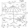
- Figure 10 shows an article in the form of a napkin or other article with a substantially square shape, to be folded in four along the two folding lines LX and LY indicated in Figure.
- the product is equipped with a principal embossed pattern, approximately centered with respect to the article, and composed in the example of a beach umbrella and a deck chair.
- the folding lines LX and LY when the article is folded, one of the two elements (the deck chair) forming the principal embossed pattern (formed by combination of the two elements, deck chair and beach umbrella) is visible on the face that remains exposed.
- the effect obtained is similar to that of the pattern in Figures 8 and 9 , although with two elements that are not part of each other (like the slice with respect to the fruit in Figures 8 and 9 ), but are two different and separate objects.
- Extending along the edges indicated with B1, B2, B3 and B4 of the finished product are the secondary embossed patterns, having the functions already described, and namely to glue the plies forming the napkin up to the edges, and make contact between the embossing roller and the pressure roller continuous during production.
- the invention also provides for an embossed web material comprising at least two plies of tissue paper joined by gluing and forming at least one multi-ply sheet, characterized in that said sheet has a principal embossed pattern, in a substantially intermediate position with re-spectto the surface of the article, said pattern comprising at least two portions, which form a complete decoration that can be observed when the article is opened, one of said portions in turn forming a different complete decoration, fully visible on a face of the article exposed when said article is folded.
Claims (15)
- Walze (21) zur Verarbeitung von Lagen aus Bahnmaterial, insbesondere von Lagen aus Papier, welche erhabene Bereiche umfasst, die Prägemuster auf der zylindrischen Oberfläche der Walze definieren, gekennzeichnet durch: eine Reihe von umfänglichen oder ringförmigen Bändern (21C), die voneinander beabstandet sind, wobei innerhalb derselben ein erstes sekundäres Prägemuster (D) erzeugt wird; eine Reihe von Längsbändern (21L), die sich in Längsrichtung entlang der Walze erstrecken, wobei sie in konstantem Abstand zueinander angeordnet sind, wobei innerhalb derselben ein zweites sekundäres Prägemuster (L) erzeugt wird; wobei die Umfangs- und Längsbänder Rechtecke definieren, innerhalb derer jeweils ein dazwischen angeordnetes Hauptprägemuster erzeugt wird; und wobei die Längsbänder in Bezug auf die Achse der Walze schräg angeordnet sind.
- Walze nach Anspruch 1, dadurch gekennzeichnet, dass die Längsbänder schräg mit einem einzeln oder mehrfach V-förmigen Verlauf angeordnet sind.
- Walze nach Anspruch 1 oder 2, dadurch gekennzeichnet, dass die Längsbänder eine Neigung zwischen 0° 30' und 10° und vorzugsweise zwischen 1° und 5° in Bezug auf die Achse der Walze, das heißt in Bezug auf eine Mantellinie der Walze, aufweisen.
- Walze nach einem oder mehreren der Ansprüche 1 bis 3, dadurch gekennzeichnet, dass die Längsbänder aus aufeinanderfolgend angeordneten Abschnitten bestehen, die jeweils parallel zur Achse der Walze, aber versetzt zueinander angeordnet sind, wobei die Abschnitte durch den Schnittpunkt eines Längsbandes mit den ringförmigen Bändern definiert sind.
- Walze nach einem oder mehreren der Ansprüche 1 bis 4, dadurch gekennzeichnet, dass das geprägte Hauptmuster an einer im Wesentlichen zentrierten Position innerhalb des jeweiligen Rechtecks angeordnet ist.
- Walze nach einem oder mehreren der Ansprüche 1 bis 5, dadurch gekennzeichnet, dass jedes geprägte Hauptmuster ein komplexes und sich nicht wiederholendes Muster darstellt, das durch eine Mehrzahl von miteinander kombinierten Erhebungen gebildet wird.
- Walze nach einem oder mehreren der Ansprüche 1 bis 6, dadurch gekennzeichnet, dass die Erhebungen, die das erste geprägte sekundäre Muster, das zweite geprägte sekundäre Muster und das geprägte Hauptmuster bilden, derart angeordnet und konfiguriert sind, dass eine beliebige Mantellinie auf der zylindrischen Oberfläche der Walze eine Mehrzahl der Erhebungen schneidet.
- Walze nach Anspruch 7, dadurch gekennzeichnet, dass die Summe der Segmente jeder Mantellinie, die auf der Prägewalze durch die einzelnen von der Mantellinie durchschnittenen geprägten Erhebungen begrenzt werden, zwischen 5% und 30% der gesamten axialen Länge der Walze ausmacht.
- Walze nach einem oder mehreren der Ansprüche 1 bis 8, dadurch gekennzeichnet, dass die geprägten Hauptmuster zweier aufeinanderfolgender ringförmiger Abschnitte in Umfangsrichtung zueinander versetzt sind.
- Walze nach einem oder mehreren der Ansprüche 1 bis 9, dadurch gekennzeichnet, dass in mindestens einigen der einzelnen Rechtecke jedes ringförmigen Abschnitts geprägte Hauptmuster angeordnet sind, die sich voneinander unterscheiden.
- Walze nach Anspruch 9 und 10, dadurch gekennzeichnet, dass zwei benachbarte ringförmige Abschnitte die gleiche Sequenz von geprägten Hauptmustern aufweisen, wobei die beiden Sequenzen schräg zueinander versetzt sind, und zwar um mindestens einen Schritt, der einem Rechteck entspricht.
- Prägeeinheit, die eine Andruckwalze, einen Leimverteiler und eine Prägewalze gemäß einem oder mehreren der Ansprüche 1 bis 11 umfasst.
- Produktionslinie zur Herstellung eines geprägten Bahnmaterials mit mindestens zwei Lagen, die durch Prägen und Kleben miteinander verbunden werden, umfassend:zumindest einen ersten Zuführweg für eine erste Lage und einen zweiten Zuführweg für eine zweite Lage;
 eine Prägeeinheit, die mindestens eine Prägewalze, eine mit der Prägewalze zusammenwirkende Andruckwalze und ein Leimwerk umfasst;nachgeordnet der Prägeeinheit, einen Perforator zum Perforieren des Bahnmaterials entlang von Linien im Wesentlichen quer zur Längserstreckung des Bahnmaterials, dadurch gekennzeichnet, dass die Prägewalze eine Prägewalze gemäß einem oder mehrerer der Ansprüche 1 bis 11 darstellt.
 - Produktionslinie nach Anspruch 13, dadurch gekennzeichnet, dass der Perforator mit der Prägeeinheit derart synchronisiert ist, dass die von dem Perforator erzeugten Perforationslinien innerhalb der Breite der Längsbänder liegen, die das zweite geprägte sekundäre Muster enthalten.
- Produktionslinie nach Anspruch 13 oder 14, dadurch gekennzeichnet, dass diese nachgeordnet dem Perforator eine Umwickelmaschine umfasst, um das geprägte Bahnmaterial zu Langrollen zu wickeln, und nachgeordnet der Umwickelmaschine eine Schneidemaschine, um jede Langrolle mit entsprechenden Schnitten senkrecht zur Achse der Langrollen in Rollen zu schneiden, wobei die Schneidemaschine derart mit der Prägeeinheit synchronisiert ist, dass die einzelnen Rollen entlang von Schnittebenen geteilt werden, die in den umfänglichen oder ringförmigen Bänder liegen.
Applications Claiming Priority (2)
| Application Number | Priority Date | Filing Date | Title |
|---|---|---|---|
| IT000033A ITFI20050033A1 (it) | 2005-03-01 | 2005-03-01 | Rullo goffratore, dispositivo goffratore comprendente detto rullo ed articolo di materiale cartaceo realizzato con detto dispositivo goffratore |
| PCT/IT2006/000112 WO2006092817A1 (en) | 2005-03-01 | 2006-02-27 | Embossing roller, embossing device including said roller and paper article produced with said embossing device |
Publications (3)
| Publication Number | Publication Date |
|---|---|
| EP1855876A1 EP1855876A1 (de) | 2007-11-21 |
| EP1855876B1 EP1855876B1 (de) | 2012-02-08 |
| EP1855876B2 true EP1855876B2 (de) | 2021-01-27 |
Family
ID=36593718
Family Applications (1)
| Application Number | Title | Priority Date | Filing Date |
|---|---|---|---|
| EP06711441.3A Active EP1855876B2 (de) | 2005-03-01 | 2006-02-27 | Prägerolle, prägevorrichtung mit der rolle |
Country Status (7)
| Country | Link |
|---|---|
| US (1) | US20080199660A1 (de) |
| EP (1) | EP1855876B2 (de) |
| AT (1) | ATE544590T1 (de) |
| BR (1) | BRPI0609374A2 (de) |
| ES (1) | ES2380788T3 (de) |
| IT (1) | ITFI20050033A1 (de) |
| WO (1) | WO2006092817A1 (de) |
Families Citing this family (32)
| Publication number | Priority date | Publication date | Assignee | Title |
|---|---|---|---|---|
| US20080216975A1 (en) * | 2007-03-05 | 2008-09-11 | James Paul Farwig | Deeply embossed roll paper products having reduced gapping on the machine direction edges |
| FR2914170B1 (fr) * | 2007-03-28 | 2012-08-31 | Georgia Pacific France | Rouleau de produit cellulosique fibreux |
| CA2686189A1 (en) * | 2007-04-05 | 2008-10-16 | Imperial Tobacco Canada Limited | Apparatus and method for producing embossed paper or laminated metallic foil sheets |
| EP2277690A1 (de) * | 2009-07-23 | 2011-01-26 | Andrea Galeotti | Prägewalze mit mehreren Sequenzentwürfen |
| DE112010003640T5 (de) * | 2009-09-14 | 2012-08-02 | ACCO Brands Corporation | Laminiermaterial und Verfahren zur Herstellung |
| US8287977B2 (en) * | 2010-06-21 | 2012-10-16 | The Procter & Gamble Company | Uniquely perforated web product |
| US8283013B2 (en) * | 2010-06-21 | 2012-10-09 | The Procter & Gamble Company | Uniquely perforated web product |
| US8287976B2 (en) * | 2010-06-21 | 2012-10-16 | The Procter & Gamble Company | Uniquely perforated web product |
| US8468938B2 (en) * | 2010-06-21 | 2013-06-25 | The Procter & Gamble Company | Apparatus for perforating a web material |
| EP2468493A1 (de) * | 2010-12-23 | 2012-06-27 | Boegli-Gravures S.A. | Vorrichtung zum Prägen von Folien |
| ITBO20110502A1 (it) * | 2011-08-26 | 2013-02-27 | Infibra S R L | Metodo per ottenere tovaglioli di carta a più veli ed apparato che attua tale metodo |
| WO2013188379A1 (en) | 2012-06-11 | 2013-12-19 | Unipixel Displays, Inc. | Methods of manufacture and use of customized flexomaster patterns for flexographic printing |
| JP6069978B2 (ja) * | 2012-09-07 | 2017-02-01 | 大日本印刷株式会社 | シート、ハイトデータ処理装置、ハイトデータ処理方法、プログラム、エンボス版製造装置、エンボス版製造方法 |
| CN102990983B (zh) * | 2012-12-11 | 2015-07-15 | 金红叶纸业集团有限公司 | 压花辊及应用其制得的纸张 |
| DE102013101118A1 (de) * | 2013-02-05 | 2014-08-21 | Focke & Co. (Gmbh & Co. Kg) | Verfahren und Vorrichtung zur Herstellung von Zuschnitten für Kragen von Packungen für Zigaretten |
| EP2958831B1 (de) * | 2013-02-21 | 2017-05-31 | The Procter and Gamble Company | Packung mit kernrollen aus fasermaterial |
| US20140346704A1 (en) * | 2013-05-22 | 2014-11-27 | The Procter & Gamble Company | Method for producing an absorbent paper product having visual elements |
| US20150000854A1 (en) * | 2013-06-27 | 2015-01-01 | The Procter & Gamble Company | Sheet products bearing designs that vary among successive sheets, and apparatus and methods for producing the same |
| US20150001783A1 (en) * | 2013-06-27 | 2015-01-01 | The Procter & Gamble Company | Sheet products bearing designs that vary among successive sheets, and apparatus and methods for producing the same |
| EP2975177A1 (de) * | 2014-07-17 | 2016-01-20 | Sca Tissue France | Saugfähige Blattproduktstreifen mit begrenzter Flüssigkeitsdurchbrucheigenschaft |
| JP6589308B2 (ja) * | 2015-03-16 | 2019-10-16 | 王子ホールディングス株式会社 | エンボスが付与されたペーパーロール及びロール製品の製造方法 |
| KR101813341B1 (ko) * | 2015-12-28 | 2017-12-28 | 삼성전기주식회사 | 자성체 시트 제조방법 및 자성체 시트 제조용 롤러 |
| IT201600074059A1 (it) * | 2016-07-15 | 2018-01-15 | Massimiliano Conte | Dispositivo per la produzione di tovaglioli di carta multi velo goffrati a riquadro. |
| CN109466120A (zh) * | 2018-09-04 | 2019-03-15 | 佛山市宝索机械制造有限公司 | 纸材无胶复合装置 |
| JP7455837B2 (ja) * | 2018-12-21 | 2024-03-26 | ジェイティー インターナショナル エスエイ | エンボス加工されたチップペーパー及びエンボス加工されたチップペーパーを用いて喫煙物品を製造する方法 |
| WO2021201713A1 (ru) * | 2020-04-03 | 2021-10-07 | Елена Анатольевна ПЫЖОВА | Способ и устройство тиснения листовых или рулонных материалов |
| JP2023520945A (ja) | 2020-04-10 | 2023-05-22 | ケルベール ティッシュ ソチエタ ペル アチオーニ | エンボス・ラミネート加工装置におけるエンボス加工ローラの加熱方法及び装置 |
| US20220284828A1 (en) * | 2021-03-02 | 2022-09-08 | Jaime MCCLELLAND | Toilet tissue product with printed training symbol or marker and method of manufacturing the same |
| IT202100017675A1 (it) | 2021-07-05 | 2023-01-05 | Koerber Tissue S P A | Dispositivo goffratore con almeno un rullo goffratore riscaldato, e metodo |
| IT202100019499A1 (it) | 2021-07-22 | 2023-01-22 | Koerber Tissue S P A | Un goffratore a rulli multipli e metodo |
| WO2023104741A1 (en) | 2021-12-07 | 2023-06-15 | Körber Tissue S.p.A. | Embossing device for embossing a cellulose web material and related method |
| IT202200003380A1 (it) | 2022-02-23 | 2023-08-23 | Engraving Solutions S R L | Rullo goffratore, metodo di incisione e goffratore comprendente il rullo goffratore |
Citations (2)
| Publication number | Priority date | Publication date | Assignee | Title |
|---|---|---|---|---|
| DE19534812A1 (de) † | 1995-09-20 | 1997-03-27 | Pwa Hygienepapiere Gmbh | Mehrlagiges bahnförmiges Tissueprodukt mit ungeprägter Mittellage, seine Herstellung und Einrichtung zu seiner Erzeugung |
| EP0893242A1 (de) † | 1997-07-18 | 1999-01-27 | Fort James France | Verfahren zur Herstellung von Zellulosefaserprodukten, insbesondere Taschentüchern oder Handtüchern |
Family Cites Families (12)
| Publication number | Priority date | Publication date | Assignee | Title |
|---|---|---|---|---|
| US1954635A (en) * | 1929-10-02 | 1934-04-10 | Orenda Corp | Sheet forming device |
| US2890540A (en) * | 1955-10-18 | 1959-06-16 | Scott Paper Co | Paper napkin |
| US3673060A (en) * | 1970-01-12 | 1972-06-27 | Int Paper Co | Adhesively laminated creped dinner napkin |
| US3694300A (en) * | 1971-08-27 | 1972-09-26 | Paper Converting Machine Co | Base product for textile replacement and method of producing the same |
| US4320162A (en) * | 1980-05-15 | 1982-03-16 | American Can Company | Multi-ply fibrous sheet structure and its manufacture |
| FR2604734B1 (fr) * | 1986-10-02 | 1989-01-06 | Beghin Say Sa | Feuille stratifiee absorbante |
| US5415918A (en) * | 1993-12-22 | 1995-05-16 | James River Corporation Of Virginia | Functional emboss design for multi-ply napkins |
| FR2721251B1 (fr) * | 1994-06-17 | 1996-07-26 | Kaysersberg Sa | Feuille multicouche de papier absorbant, son procédé de fabrication. |
| IT1307887B1 (it) * | 1999-06-18 | 2001-11-19 | Perini Fabio Spa | Metodo e dispositivo di goffratura per la produzione di materialenastriforme multivelo, e prodotto cosi' ottenuto. |
| US6686168B1 (en) * | 1999-11-04 | 2004-02-03 | Zymogenetics, Inc. | Cell surface display of proteins by recombinant host cells |
| EP1149552A1 (de) * | 2000-04-28 | 2001-10-31 | Georgia-Pacific France | Absorbierendes Papierprodukt wie Servietten oder Taschentücher, Verfahren zur Herstellung und Vorrichtungen zur Durchführung dieser Verfahren |
| EP1391174B1 (de) * | 2002-08-22 | 2008-07-23 | Georgia-Pacific France | Rolle aus Zellstoffwatteblättern und Verfahren zu ihrer Herstellung |
-
2005
- 2005-03-01 IT IT000033A patent/ITFI20050033A1/it unknown
-
2006
- 2006-02-27 EP EP06711441.3A patent/EP1855876B2/de active Active
- 2006-02-27 WO PCT/IT2006/000112 patent/WO2006092817A1/en not_active Application Discontinuation
- 2006-02-27 US US11/885,424 patent/US20080199660A1/en not_active Abandoned
- 2006-02-27 BR BRPI0609374-4A patent/BRPI0609374A2/pt not_active IP Right Cessation
- 2006-02-27 ES ES06711441T patent/ES2380788T3/es active Active
- 2006-02-27 AT AT06711441T patent/ATE544590T1/de active
Patent Citations (2)
| Publication number | Priority date | Publication date | Assignee | Title |
|---|---|---|---|---|
| DE19534812A1 (de) † | 1995-09-20 | 1997-03-27 | Pwa Hygienepapiere Gmbh | Mehrlagiges bahnförmiges Tissueprodukt mit ungeprägter Mittellage, seine Herstellung und Einrichtung zu seiner Erzeugung |
| EP0893242A1 (de) † | 1997-07-18 | 1999-01-27 | Fort James France | Verfahren zur Herstellung von Zellulosefaserprodukten, insbesondere Taschentüchern oder Handtüchern |
Also Published As
| Publication number | Publication date |
|---|---|
| US20080199660A1 (en) | 2008-08-21 |
| ES2380788T3 (es) | 2012-05-18 |
| ITFI20050033A1 (it) | 2006-09-02 |
| EP1855876B1 (de) | 2012-02-08 |
| ATE544590T1 (de) | 2012-02-15 |
| EP1855876A1 (de) | 2007-11-21 |
| BRPI0609374A2 (pt) | 2010-03-30 |
| WO2006092817A1 (en) | 2006-09-08 |
Similar Documents
| Publication | Publication Date | Title |
|---|---|---|
| EP1855876B2 (de) | Prägerolle, prägevorrichtung mit der rolle | |
| CA2377380C (en) | Device for the production of multi-ply web material with different size and density patterns on different plies | |
| US7799168B2 (en) | Method of manufacturing a hygiene paper product, apparatus for such manufacture and hygiene paper product | |
| EP1713635B1 (de) | Präge- und laminierverfahren und -vorrichtung zur herstellung von mehrlagigen bahnprodukten und entsprechendes produkt | |
| EP1786713B1 (de) | Flächenprodukt mit mindestens zwei durch verkleben verbundenen lagen mit nicht einheitlicher verteilung des klebstoffs | |
| AU2015383547B2 (en) | A coreless roll and a manufacturing method | |
| CA2682218A1 (en) | Roll of fibrous cellulosic product | |
| EP1677988B1 (de) | Verfahren zur herstellung eines hygienepapierprodukts, vorrichtung für solch eine herstellung und hygienepapierprodukt | |
| EP1970193B1 (de) | Geprägtes bahnförmiges Material, Prägeeinheit und Herstellungsverfahren dafür | |
| EP1897682B1 (de) | Verfahren und Vorrichtung zur Herstellung eines geprägten und gefärbten Bahnmaterials | |
| EP1849914B1 (de) | Verfahren und system zum verarbeiten von tissuepapier unter verwendung von nassverfestigungsmitteln | |
| US20050132904A1 (en) | Process for packaging products in roll and associated cylinder | |
| EP1651427B1 (de) | Verfahren und vorrichtung zur herstellung eines geprägten und gedruckten produkts und dadurch erhaltenes produkt | |
| EP1849729B1 (de) | Verfahren und System zur Verarbeitung von Tissuepapier durch die gleichzeitige Verwendung von Papierrollen mit unterschiedlichen Eigenschaften | |
| EP2252455A1 (de) | Geprägtes mehrlagiges papiermaterial und prägeeinheit zu seiner herstellung | |
| EP3578352A1 (de) | Prägeverfahren und produkt | |
| BRPI0609374B1 (pt) | Rolo de material plano flexível fibroso, rolete para processar dobras do material plano flexível fibroso, unidade de estampar em relevo e linha de produção para produzir artigo de material plano flexível fibroso | |
| WO2007004242A2 (en) | A multi-use paper product and device for the production thereof |
Legal Events
| Date | Code | Title | Description |
|---|---|---|---|
| PUAI | Public reference made under article 153(3) epc to a published international application that has entered the european phase |
Free format text: ORIGINAL CODE: 0009012 |
|
| 17P | Request for examination filed |
Effective date: 20070803 |
|
| AK | Designated contracting states |
Kind code of ref document: A1 Designated state(s): AT BE BG CH CY CZ DE DK EE ES FI FR GB GR HU IE IS IT LI LT LU LV MC NL PL PT RO SE SI SK TR |
|
| 17Q | First examination report despatched |
Effective date: 20071220 |
|
| DAX | Request for extension of the european patent (deleted) | ||
| GRAP | Despatch of communication of intention to grant a patent |
Free format text: ORIGINAL CODE: EPIDOSNIGR1 |
|
| RIN1 | Information on inventor provided before grant (corrected) |
Inventor name: GELLI, MAURO |
|
| GRAS | Grant fee paid |
Free format text: ORIGINAL CODE: EPIDOSNIGR3 |
|
| GRAA | (expected) grant |
Free format text: ORIGINAL CODE: 0009210 |
|
| AK | Designated contracting states |
Kind code of ref document: B1 Designated state(s): AT BE BG CH CY CZ DE DK EE ES FI FR GB GR HU IE IS IT LI LT LU LV MC NL PL PT RO SE SI SK TR |
|
| REG | Reference to a national code |
Ref country code: GB Ref legal event code: FG4D |
|
| REG | Reference to a national code |
Ref country code: AT Ref legal event code: REF Ref document number: 544590 Country of ref document: AT Kind code of ref document: T Effective date: 20120215 Ref country code: CH Ref legal event code: EP |
|
| REG | Reference to a national code |
Ref country code: DE Ref legal event code: R096 Ref document number: 602006027526 Country of ref document: DE Effective date: 20120412 |
|
| REG | Reference to a national code |
Ref country code: ES Ref legal event code: FG2A Ref document number: 2380788 Country of ref document: ES Kind code of ref document: T3 Effective date: 20120518 |
|
| REG | Reference to a national code |
Ref country code: NL Ref legal event code: VDEP Effective date: 20120208 |
|
| LTIE | Lt: invalidation of european patent or patent extension |
Effective date: 20120208 |
|
| PG25 | Lapsed in a contracting state [announced via postgrant information from national office to epo] |
Ref country code: IS Free format text: LAPSE BECAUSE OF FAILURE TO SUBMIT A TRANSLATION OF THE DESCRIPTION OR TO PAY THE FEE WITHIN THE PRESCRIBED TIME-LIMIT Effective date: 20120608 Ref country code: NL Free format text: LAPSE BECAUSE OF FAILURE TO SUBMIT A TRANSLATION OF THE DESCRIPTION OR TO PAY THE FEE WITHIN THE PRESCRIBED TIME-LIMIT Effective date: 20120208 Ref country code: LT Free format text: LAPSE BECAUSE OF FAILURE TO SUBMIT A TRANSLATION OF THE DESCRIPTION OR TO PAY THE FEE WITHIN THE PRESCRIBED TIME-LIMIT Effective date: 20120208 |
|
| PG25 | Lapsed in a contracting state [announced via postgrant information from national office to epo] |
Ref country code: FI Free format text: LAPSE BECAUSE OF FAILURE TO SUBMIT A TRANSLATION OF THE DESCRIPTION OR TO PAY THE FEE WITHIN THE PRESCRIBED TIME-LIMIT Effective date: 20120208 Ref country code: BE Free format text: LAPSE BECAUSE OF FAILURE TO SUBMIT A TRANSLATION OF THE DESCRIPTION OR TO PAY THE FEE WITHIN THE PRESCRIBED TIME-LIMIT Effective date: 20120208 Ref country code: GR Free format text: LAPSE BECAUSE OF FAILURE TO SUBMIT A TRANSLATION OF THE DESCRIPTION OR TO PAY THE FEE WITHIN THE PRESCRIBED TIME-LIMIT Effective date: 20120509 Ref country code: LV Free format text: LAPSE BECAUSE OF FAILURE TO SUBMIT A TRANSLATION OF THE DESCRIPTION OR TO PAY THE FEE WITHIN THE PRESCRIBED TIME-LIMIT Effective date: 20120208 Ref country code: PT Free format text: LAPSE BECAUSE OF FAILURE TO SUBMIT A TRANSLATION OF THE DESCRIPTION OR TO PAY THE FEE WITHIN THE PRESCRIBED TIME-LIMIT Effective date: 20120608 Ref country code: PL Free format text: LAPSE BECAUSE OF FAILURE TO SUBMIT A TRANSLATION OF THE DESCRIPTION OR TO PAY THE FEE WITHIN THE PRESCRIBED TIME-LIMIT Effective date: 20120208 |
|
| REG | Reference to a national code |
Ref country code: AT Ref legal event code: MK05 Ref document number: 544590 Country of ref document: AT Kind code of ref document: T Effective date: 20120208 |
|
| PG25 | Lapsed in a contracting state [announced via postgrant information from national office to epo] |
Ref country code: CY Free format text: LAPSE BECAUSE OF FAILURE TO SUBMIT A TRANSLATION OF THE DESCRIPTION OR TO PAY THE FEE WITHIN THE PRESCRIBED TIME-LIMIT Effective date: 20120208 Ref country code: MC Free format text: LAPSE BECAUSE OF NON-PAYMENT OF DUE FEES Effective date: 20120229 |
|
| REG | Reference to a national code |
Ref country code: CH Ref legal event code: PL |
|
| PG25 | Lapsed in a contracting state [announced via postgrant information from national office to epo] |
Ref country code: EE Free format text: LAPSE BECAUSE OF FAILURE TO SUBMIT A TRANSLATION OF THE DESCRIPTION OR TO PAY THE FEE WITHIN THE PRESCRIBED TIME-LIMIT Effective date: 20120208 Ref country code: RO Free format text: LAPSE BECAUSE OF FAILURE TO SUBMIT A TRANSLATION OF THE DESCRIPTION OR TO PAY THE FEE WITHIN THE PRESCRIBED TIME-LIMIT Effective date: 20120208 Ref country code: LI Free format text: LAPSE BECAUSE OF NON-PAYMENT OF DUE FEES Effective date: 20120229 Ref country code: CH Free format text: LAPSE BECAUSE OF NON-PAYMENT OF DUE FEES Effective date: 20120229 Ref country code: DK Free format text: LAPSE BECAUSE OF FAILURE TO SUBMIT A TRANSLATION OF THE DESCRIPTION OR TO PAY THE FEE WITHIN THE PRESCRIBED TIME-LIMIT Effective date: 20120208 Ref country code: CZ Free format text: LAPSE BECAUSE OF FAILURE TO SUBMIT A TRANSLATION OF THE DESCRIPTION OR TO PAY THE FEE WITHIN THE PRESCRIBED TIME-LIMIT Effective date: 20120208 Ref country code: SE Free format text: LAPSE BECAUSE OF FAILURE TO SUBMIT A TRANSLATION OF THE DESCRIPTION OR TO PAY THE FEE WITHIN THE PRESCRIBED TIME-LIMIT Effective date: 20120208 Ref country code: SI Free format text: LAPSE BECAUSE OF FAILURE TO SUBMIT A TRANSLATION OF THE DESCRIPTION OR TO PAY THE FEE WITHIN THE PRESCRIBED TIME-LIMIT Effective date: 20120208 |
|
| PLBI | Opposition filed |
Free format text: ORIGINAL CODE: 0009260 |
|
| REG | Reference to a national code |
Ref country code: IE Ref legal event code: MM4A |
|
| PG25 | Lapsed in a contracting state [announced via postgrant information from national office to epo] |
Ref country code: SK Free format text: LAPSE BECAUSE OF FAILURE TO SUBMIT A TRANSLATION OF THE DESCRIPTION OR TO PAY THE FEE WITHIN THE PRESCRIBED TIME-LIMIT Effective date: 20120208 |
|
| PLAX | Notice of opposition and request to file observation + time limit sent |
Free format text: ORIGINAL CODE: EPIDOSNOBS2 |
|
| 26 | Opposition filed |
Opponent name: SCA HYGIENE PRODUCTS AB Effective date: 20121108 |
|
| PG25 | Lapsed in a contracting state [announced via postgrant information from national office to epo] |
Ref country code: IE Free format text: LAPSE BECAUSE OF NON-PAYMENT OF DUE FEES Effective date: 20120227 Ref country code: AT Free format text: LAPSE BECAUSE OF FAILURE TO SUBMIT A TRANSLATION OF THE DESCRIPTION OR TO PAY THE FEE WITHIN THE PRESCRIBED TIME-LIMIT Effective date: 20120208 |
|
| REG | Reference to a national code |
Ref country code: DE Ref legal event code: R026 Ref document number: 602006027526 Country of ref document: DE Effective date: 20121108 |
|
| PLAB | Opposition data, opponent's data or that of the opponent's representative modified |
Free format text: ORIGINAL CODE: 0009299OPPO |
|
| PLAF | Information modified related to communication of a notice of opposition and request to file observations + time limit |
Free format text: ORIGINAL CODE: EPIDOSCOBS2 |
|
| R26 | Opposition filed (corrected) |
Opponent name: SCA HYGIENE PRODUCTS AB Effective date: 20121108 |
|
| PLBB | Reply of patent proprietor to notice(s) of opposition received |
Free format text: ORIGINAL CODE: EPIDOSNOBS3 |
|
| PG25 | Lapsed in a contracting state [announced via postgrant information from national office to epo] |
Ref country code: BG Free format text: LAPSE BECAUSE OF FAILURE TO SUBMIT A TRANSLATION OF THE DESCRIPTION OR TO PAY THE FEE WITHIN THE PRESCRIBED TIME-LIMIT Effective date: 20120508 |
|
| PG25 | Lapsed in a contracting state [announced via postgrant information from national office to epo] |
Ref country code: TR Free format text: LAPSE BECAUSE OF FAILURE TO SUBMIT A TRANSLATION OF THE DESCRIPTION OR TO PAY THE FEE WITHIN THE PRESCRIBED TIME-LIMIT Effective date: 20120208 |
|
| PG25 | Lapsed in a contracting state [announced via postgrant information from national office to epo] |
Ref country code: LU Free format text: LAPSE BECAUSE OF NON-PAYMENT OF DUE FEES Effective date: 20120227 |
|
| PG25 | Lapsed in a contracting state [announced via postgrant information from national office to epo] |
Ref country code: HU Free format text: LAPSE BECAUSE OF FAILURE TO SUBMIT A TRANSLATION OF THE DESCRIPTION OR TO PAY THE FEE WITHIN THE PRESCRIBED TIME-LIMIT Effective date: 20060227 |
|
| RDAF | Communication despatched that patent is revoked |
Free format text: ORIGINAL CODE: EPIDOSNREV1 |
|
| REG | Reference to a national code |
Ref country code: FR Ref legal event code: PLFP Year of fee payment: 10 |
|
| APBM | Appeal reference recorded |
Free format text: ORIGINAL CODE: EPIDOSNREFNO |
|
| APBP | Date of receipt of notice of appeal recorded |
Free format text: ORIGINAL CODE: EPIDOSNNOA2O |
|
| APAH | Appeal reference modified |
Free format text: ORIGINAL CODE: EPIDOSCREFNO |
|
| RAP2 | Party data changed (patent owner data changed or rights of a patent transferred) |
Owner name: FABIO PERINI S.P.A. |
|
| APBQ | Date of receipt of statement of grounds of appeal recorded |
Free format text: ORIGINAL CODE: EPIDOSNNOA3O |
|
| REG | Reference to a national code |
Ref country code: FR Ref legal event code: PLFP Year of fee payment: 11 |
|
| REG | Reference to a national code |
Ref country code: FR Ref legal event code: PLFP Year of fee payment: 12 |
|
| REG | Reference to a national code |
Ref country code: FR Ref legal event code: PLFP Year of fee payment: 13 |
|
| PLAB | Opposition data, opponent's data or that of the opponent's representative modified |
Free format text: ORIGINAL CODE: 0009299OPPO |
|
| R26 | Opposition filed (corrected) |
Opponent name: ESSITY HYGIENE AND HEALTH AKTIEBOLAG Effective date: 20121108 |
|
| APBU | Appeal procedure closed |
Free format text: ORIGINAL CODE: EPIDOSNNOA9O |
|
| PGFP | Annual fee paid to national office [announced via postgrant information from national office to epo] |
Ref country code: FR Payment date: 20190226 Year of fee payment: 14 |
|
| PLAY | Examination report in opposition despatched + time limit |
Free format text: ORIGINAL CODE: EPIDOSNORE2 |
|
| PLBC | Reply to examination report in opposition received |
Free format text: ORIGINAL CODE: EPIDOSNORE3 |
|
| PGFP | Annual fee paid to national office [announced via postgrant information from national office to epo] |
Ref country code: GB Payment date: 20200226 Year of fee payment: 15 |
|
| PGFP | Annual fee paid to national office [announced via postgrant information from national office to epo] |
Ref country code: DE Payment date: 20200429 Year of fee payment: 15 |
|
| PUAH | Patent maintained in amended form |
Free format text: ORIGINAL CODE: 0009272 |
|
| STAA | Information on the status of an ep patent application or granted ep patent |
Free format text: STATUS: PATENT MAINTAINED AS AMENDED |
|
| 27A | Patent maintained in amended form |
Effective date: 20210127 |
|
| AK | Designated contracting states |
Kind code of ref document: B2 Designated state(s): AT BE BG CH CY CZ DE DK EE ES FI FR GB GR HU IE IS IT LI LT LU LV MC NL PL PT RO SE SI SK TR |
|
| REG | Reference to a national code |
Ref country code: DE Ref legal event code: R102 Ref document number: 602006027526 Country of ref document: DE |
|
| PG25 | Lapsed in a contracting state [announced via postgrant information from national office to epo] |
Ref country code: FR Free format text: LAPSE BECAUSE OF NON-PAYMENT OF DUE FEES Effective date: 20200229 |
|
| REG | Reference to a national code |
Ref country code: DE Ref legal event code: R119 Ref document number: 602006027526 Country of ref document: DE |
|
| GBPC | Gb: european patent ceased through non-payment of renewal fee |
Effective date: 20210227 |
|
| PG25 | Lapsed in a contracting state [announced via postgrant information from national office to epo] |
Ref country code: ES Free format text: LAPSE BECAUSE OF FAILURE TO SUBMIT A TRANSLATION OF THE DESCRIPTION OR TO PAY THE FEE WITHIN THE PRESCRIBED TIME-LIMIT Effective date: 20210127 |
|
| PG25 | Lapsed in a contracting state [announced via postgrant information from national office to epo] |
Ref country code: GB Free format text: LAPSE BECAUSE OF NON-PAYMENT OF DUE FEES Effective date: 20210227 Ref country code: DE Free format text: LAPSE BECAUSE OF NON-PAYMENT OF DUE FEES Effective date: 20210901 |
|
| PGFP | Annual fee paid to national office [announced via postgrant information from national office to epo] |
Ref country code: IT Payment date: 20230220 Year of fee payment: 18 |
|
| P01 | Opt-out of the competence of the unified patent court (upc) registered |
Effective date: 20230530 |