EP1855056B1 - Rauchgaskanal mit einem Grobascheabscheider - Google Patents
Rauchgaskanal mit einem Grobascheabscheider Download PDFInfo
- Publication number
- EP1855056B1 EP1855056B1 EP07009306.7A EP07009306A EP1855056B1 EP 1855056 B1 EP1855056 B1 EP 1855056B1 EP 07009306 A EP07009306 A EP 07009306A EP 1855056 B1 EP1855056 B1 EP 1855056B1
- Authority
- EP
- European Patent Office
- Prior art keywords
- flue gas
- sieve
- gas channel
- ash
- surface sections
- Prior art date
- Legal status (The legal status is an assumption and is not a legal conclusion. Google has not performed a legal analysis and makes no representation as to the accuracy of the status listed.)
- Not-in-force
Links
- UGFAIRIUMAVXCW-UHFFFAOYSA-N Carbon monoxide Chemical compound [O+]#[C-] UGFAIRIUMAVXCW-UHFFFAOYSA-N 0.000 claims description 37
- 239000003546 flue gas Substances 0.000 claims description 37
- 238000011144 upstream manufacturing Methods 0.000 claims description 11
- 239000007789 gas Substances 0.000 claims description 5
- 239000002184 metal Substances 0.000 claims description 2
- JHIVVAPYMSGYDF-UHFFFAOYSA-N cyclohexanone Chemical compound O=C1CCCCC1 JHIVVAPYMSGYDF-UHFFFAOYSA-N 0.000 claims 1
- 239000002245 particle Substances 0.000 description 36
- 238000002485 combustion reaction Methods 0.000 description 10
- 239000003054 catalyst Substances 0.000 description 6
- 239000012716 precipitator Substances 0.000 description 6
- 241000196324 Embryophyta Species 0.000 description 5
- 238000000926 separation method Methods 0.000 description 4
- 230000000694 effects Effects 0.000 description 3
- 238000004140 cleaning Methods 0.000 description 2
- 230000008021 deposition Effects 0.000 description 2
- 230000005484 gravity Effects 0.000 description 2
- 230000003116 impacting effect Effects 0.000 description 2
- 238000009434 installation Methods 0.000 description 2
- 235000002017 Zea mays subsp mays Nutrition 0.000 description 1
- 241000482268 Zea mays subsp. mays Species 0.000 description 1
- 230000015572 biosynthetic process Effects 0.000 description 1
- 239000003245 coal Substances 0.000 description 1
- 239000000567 combustion gas Substances 0.000 description 1
- 230000001419 dependent effect Effects 0.000 description 1
- 230000003628 erosive effect Effects 0.000 description 1
- 230000001771 impaired effect Effects 0.000 description 1
- 238000012986 modification Methods 0.000 description 1
- 230000004048 modification Effects 0.000 description 1
- 230000008092 positive effect Effects 0.000 description 1
- 230000001172 regenerating effect Effects 0.000 description 1
- 238000012216 screening Methods 0.000 description 1
- 239000000725 suspension Substances 0.000 description 1
- 230000007704 transition Effects 0.000 description 1
- 238000004056 waste incineration Methods 0.000 description 1
- 230000037303 wrinkles Effects 0.000 description 1
Images


Classifications
-
- F—MECHANICAL ENGINEERING; LIGHTING; HEATING; WEAPONS; BLASTING
- F23—COMBUSTION APPARATUS; COMBUSTION PROCESSES
- F23J—REMOVAL OR TREATMENT OF COMBUSTION PRODUCTS OR COMBUSTION RESIDUES; FLUES
- F23J15/00—Arrangements of devices for treating smoke or fumes
- F23J15/02—Arrangements of devices for treating smoke or fumes of purifiers, e.g. for removing noxious material
- F23J15/022—Arrangements of devices for treating smoke or fumes of purifiers, e.g. for removing noxious material for removing solid particulate material from the gasflow
-
- B—PERFORMING OPERATIONS; TRANSPORTING
- B01—PHYSICAL OR CHEMICAL PROCESSES OR APPARATUS IN GENERAL
- B01D—SEPARATION
- B01D45/00—Separating dispersed particles from gases or vapours by gravity, inertia, or centrifugal forces
- B01D45/04—Separating dispersed particles from gases or vapours by gravity, inertia, or centrifugal forces by utilising inertia
- B01D45/06—Separating dispersed particles from gases or vapours by gravity, inertia, or centrifugal forces by utilising inertia by reversal of direction of flow
-
- B—PERFORMING OPERATIONS; TRANSPORTING
- B01—PHYSICAL OR CHEMICAL PROCESSES OR APPARATUS IN GENERAL
- B01D—SEPARATION
- B01D45/00—Separating dispersed particles from gases or vapours by gravity, inertia, or centrifugal forces
- B01D45/04—Separating dispersed particles from gases or vapours by gravity, inertia, or centrifugal forces by utilising inertia
- B01D45/08—Separating dispersed particles from gases or vapours by gravity, inertia, or centrifugal forces by utilising inertia by impingement against baffle separators
Definitions
- the present invention relates to a flue gas duct of a power plant, such as a coal power plant, a waste incineration plant or the like with a coarse ash separator installed therein or arranged thereon.
- ash particles are generated, which are partially withdrawn directly via an ash hopper from the combustion chamber and partially entrained by the combustion or flue gas flow resulting from the combustion.
- the large volume ash particles entrained in the flow also referred to as Large Particle Ash (LPA) or Popcorn Ash
- LPA Large Particle Ash
- Popcorn Ash can lead to clogging of subsequently arranged plant components, such as catalysts, regenerative air preheaters, or the like, thereby increasing the function of the corresponding components impaired and unwanted pressure losses can be generated.
- the affected components must then be properly cleaned or replaced to restore the proper operation of the power plant. This is both time and cost intensive. In the worst case, the combustion plants of the power plant for cleaning or replacement of clogged plant components must even be completely worn, resulting in significant economic losses.
- a flue gas duct with a Grobascheabscheider of the type mentioned therein is for example in the WO-A-2004/001290 described.
- the coarse ash separator is arranged upstream of a catalyst in a section of a flue gas duct and comprises a sieve which extends over substantially the entire cross section of the flue gas duct, wherein the sieve can be arranged perpendicular to the direction of extension of the flue gas duct or inclined thereto.
- the screen comprises substantially parallel, upstream directed, fold-like arranged surface portions which cause an enlargement of the screen surface, whereby the separation efficiency of the coarse ash precipitator is improved.
- the coarse ash separator for installation in or for placement on a flue gas duct comprises a screen assembly having a first screen section which extends in the intended installed state substantially transversely to the extension direction of the downstream flue gas duct.
- the screen assembly further comprises a second screen section adjoining the first screen section in the intended condition, which is inclined to the first screen section.
- the large-volume ash particles can pass into the flue gas channel essentially in two ways, namely on the one hand by direct Strömungsmitriß and on the other by entrainment from the provided upstream of the coarse ash separator ash funnel.
- the direct Strömungsmitriß is countered essentially by the second screen section of the screen assembly.
- the first sieve section of the sieve arrangement essentially prevents the massively dominating particle entry into the flue gas duct by entrainment from the ash funnel.
- the angle of inclination between the first and the second screen section is preferably ⁇ 40 °, better still ⁇ 30 °, whereby the formation of deposits on the second screen section and thus clogging of the coarse ash precipitator is reliably prevented.
- the sieve arrangement preferably has at least one slotted screen whose screening effect is realized by numerous bars arranged parallel to one another.
- the orientation of the bars indicates the direction in which ash particles impacting the slotted screen should slide off.
- the distance between the individual bars is dimensioned according to the size of the ash particles to be separated using the coarse ash separator. If, for example, ash particles with a particle size of 6.5 mm are to be deposited, then the distance between the individual bars of the slotted screen must be correspondingly smaller, for example 6 mm.
- the first screen section has a plurality of gas-permeable, angularly arranged, fold-like surface sections, wherein between the fold-like surface sections gussets are formed, which lie alternately on an inflow side and a downstream side of the sieve arrangement.
- the wrinkle structure of the first sieve section produced in this way produces a large inflow surface, which improves the separation efficiency.
- the surface sections of the first sieve section are largely in an environment with low flow velocities, which likewise has a positive effect on the separation behavior of the coarse ash precipitator. Low flue gas speeds In the area of the sieve, in particular, the service life can also have an effect, since the erosion is significantly reduced.
- the second screen section preferably includes substantially flush with the upper edges of the fold-like surface sections, wherein the second screen section preferably projects over the fold-like surface sections on the inflow side and partially covers them. In this way, a proper operation of the coarse ash separator according to the invention is ensured.
- the fold-like surface sections are advantageously connected to one another at their upstream rear deflection points in each case via a closed channel, wherein the closed channels serve as collecting channels for the separated ash particles. Due to the inclination of the fold-like surface portions, the ash particles are carried by the flow in the non-flow through closed channels at the end of each gusset space. Due to the lack of flow forces, these are then guided by gravity through the grooves in the ash funnel arranged upstream of the coarse ash separator. If the fold-like surface portions are formed as gap sieves, then the rods of the gap sieves are preferably aligned in the direction of the closed grooves, whereby the discharge effect is enhanced via the closed grooves.
- the first and / or the second screen section preferably consists of perforated metal sheets.
- the bars of the slot screens can also be welded or otherwise produced.
- the Grobascheabscheider preferably includes a vibrating or knocking device that moves the Grobascheabscheider or the sieve assembly in the intended installed state.
- the movements of the sieve arrangement cause ash particles adhering to the sieve surface to be shaken off.
- the vibrating device may, for example, be provided in the form of a vibrating device, which vibrates the sieve device at a suitable frequency.
- the sieve assembly or the entire Grobascheabscheider be kept pivotable in the intended state arranged that the sieve assembly is moved under the influence of flow forces against a stop or the like, whereby at the Screen assembly adhering ash particles are knocked off.
- return means in the form of springs or the like may be provided to realize a reciprocating motion.
- the cleaning is preferably carried out by the knocking device.
- Fig. 1 schematically shows a power plant section with a boiler 10, which comprises a combustion chamber 14 having an ash hopper 12 and a plurality of heat exchangers 16. Downstream of the heat exchanger, a further ash hopper 18 is provided, followed by a flue gas channel 20 in the flow direction, which leads to a denitrification catalyst, not shown. In the transition region between the ash hopper 18 and the flue gas duct 20 according to the invention, a coarse ash separator 22 is provided.
- ash particles are generated during combustion in the combustion chamber, which are largely deducted directly above the ash hopper 12, which in Fig. 1 indicated schematically by the arrow 24.
- a portion of the ash particles is entrained by the flue gas flow generated by the combustion in the direction of the arrows 26 to the flue gas channel 20.
- this large volume ash particles are deposited by means of Grobascheabscheiders 22, collected in the ash tray 18 and then discharged, which in Fig. 1 indicated schematically by the arrow 28.
- the catalyst channels of the denitrification catalyst have a free diameter of 6.5 mm, all particles whose maximum dimension exceeds 6 mm are deposited by means of the coarse ash precipitator 22, thereby ensuring the functioning of the denitration catalyst.
- FIG. 1 An enlarged view of the in Fig. 1
- the area marked with the circle 30 is in Fig. 2 shown.
- a perspective view of the coarse ash separator 22 is shown in FIG Fig. 3 and a side view of the coarse ash separator 22 in FIG Fig. 4 shown.
- the coarse ash separator 22 comprises a screen assembly having a first screen section 32 and a second screen section 34.
- the first screen section 32 comprises a plurality of angularly spaced surface portions 36 extending substantially perpendicular and, in the present embodiment, transverse to the direction of extension of the flue gas channel 20, between which interstices 38 are formed, which lie alternately on an inflow side and a downstream side of the coarse ash separator 22.
- the corresponding surface portions 36 are connected to each other via closed grooves 40, wherein the groove opening facing in the direction of the upstream side of the coarse ash separator 22.
- the corresponding surface sections 36 are connected to one another via plate-like end elements 42.
- the end elements can be designed both as screens and as closed sheets or plates.
- the surface portions 36 are formed as gap sieves, each of which comprises a multiplicity of rods arranged in parallel. The individual rods are in the direction of the grooves 40, in the present case oriented horizontally, to promote sliding of ash particles in the direction of the grooves 40, which is explained in more detail below.
- the second screen section 34 adjoins the first screen section 32 in the intended installed state of the coarse ash precipitator 22 and is inclined in the outflow direction by an angle ⁇ with respect to the first screen section 32, wherein the angle ⁇ ⁇ 40 °, better still ⁇ 30 ° is.
- the second screen section 34 projects beyond the surface sections 36 and over the end elements 42, whereby a cover is produced, which at least partially covers the inflow-side gusset spaces 38 and the outflow-side gusset spaces.
- the second screen section 34 is formed as a slotted screen, wherein the slits forming the bars are arranged parallel to each other and extend substantially from below upwards. As a result of this orientation of the rods, ash particles impacting on the second screen section 34 are automatically conveyed in the direction of the ash hopper 18, which is explained in more detail below.
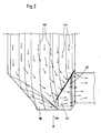
- Fig. 2 schematically shows the gas flow and the ash particle paths in the region of the purpose built Grobaschabscheiders 22, wherein the arrows 44 represent the gas flow and the solid lines 46, the ash particle paths.
- the gas flow is substantially perpendicular to almost all areas of the second screen section 34, except in the uppermost part, where the flow vector also has a downgrade component.
- the ash particles on the other hand meet by their nearly vertical direction of movement at a significant angle to the second screen section 34 and are rebounded from here rebounding in the ash hopper 18, which is favored by the orientation of the web screen plate of the second screen section 34 forming rods.
- the second screen section 34 thus essentially serves for the separation of particles entrained with the flow.
- the fold-like constructed, substantially vertically extending first screen section 32 serves essentially the deposition of ash particles, which are introduced via the ash hopper 18 in the direction of the flue gas duct 20.
- the ash particles impinge on the surface portions 36 of the upstream gullies 38 and are conveyed therefrom with the flow due to the inclination of the surface portions 36 and the orientation of the web screen plates of the surface portions 36 forming rods in the grooves 40 provided at the end of each upstream gullet 38 are. Due to the absence of flow forces in the grooves 40, the ash particles are then passed back to the ash hopper 18 as a result of the force of gravity.
- the bottom plates 48 of the coarse ash separator 22 are preferably formed closed, so that no ash particles can get into the flue gas duct 22 through these.
- the orientation of the first sieve section 32 is selected according to the orientation of the flue gas duct 20, namely substantially transversely to this.
- the orientation of the flue gas duct 20 is horizontal, which is why the surface portions 36 of the first wire section 32 extend substantially vertically upward. If, however, the flue gas duct 20 is provided at an angle to the horizontal, the direction of extension of the surface sections 36 of the first screen section 32 preferably changes accordingly.
- the Grobascheabscheider 22 advantageously has a vibrating or knocking device, not shown, via which the Grobascheabscheider 22 is moved to solve ash particles that have stuck to the Siebabites 32 and 34.
- the vibrating device can be realized, for example, by means of a vibration device which sets the coarse ash separator 22 into vibrations of a predetermined frequency.
- a knocking device can be realized purely mechanically by means of a pivotable suspension of the coarse ash separator 22, optionally by corresponding return means in the form of springs or the like, and a stop or the like, the coarse ash separator 22 being moved by the prevailing flow and knocked against the stop ,
Landscapes
- Chemical & Material Sciences (AREA)
- Chemical Kinetics & Catalysis (AREA)
- Engineering & Computer Science (AREA)
- Mechanical Engineering (AREA)
- General Engineering & Computer Science (AREA)
- Separating Particles In Gases By Inertia (AREA)
- Filtering Of Dispersed Particles In Gases (AREA)
- Incineration Of Waste (AREA)
- Waste-Gas Treatment And Other Accessory Devices For Furnaces (AREA)
Description
- Die vorliegende Erfindung betrifft einen Rauchgaskanal eines Kraftwerks, wie beispielsweise ein Kohlekraftwerk, eine Müllverbrennungsanlage oder dergleichen mit einem darin eingebauten oder an diesem angeordneten grobascheabscheider.
- Bei dem Verbrennungsprozeß in einem Kraftwerk der oben genannten Art werden Aschepartikel erzeugt, die teilweise direkt über einen Aschetrichter aus dem Verbrennungsraum abgezogen und teilweise von dem aus der Verbrennung resultierenden Abgas- bzw. Rauchgasstrom mitgerissen werden. Die von der Strömung mitgerissenen großvolumigen Aschepartikel, die auch als Large Particle Ash (LPA) oder als Popcorn Ash bezeichnet werden, können zu einer Verstopfung von nachfolgend angeordneten Anlagekomponenten, wie beispielsweise Katalysatoren, regenerativ arbeitende Luftvorwärmer oder dergleichen führen, wodurch die Funktion der entsprechenden Komponenten beeinträchtigt und unerwünschte Druckverluste erzeugt werden können. Die betroffenen Komponenten müssen dann entsprechend gereinigt oder ersetzt werden, um den ordnungsgemäßen Betrieb des Kraftwerks wiederherzustellen. Dies ist sowohl zeit- als auch kosteninten-siv. Im ungünstigsten Fall müssen die Feuerungsanlagen des Kraftwerks zum Reinigen oder Austausch der verstopften Anlagenkomponenten sogar vollständig abgefahren werden, was zu erheblichen wirtschaftlichen Einbußen führt.
- Um den Eintrag großvolumiger Aschepartikel in zu Verstopfungen neigende Anlagenteile zu verhindern, ist es bekannt, sogenannte Grobascheabscheider in den Rauchgaskanälen von Kraftwerken vorzusehen, welche die großvolumigen Aschepartikel abscheiden, bevor diese zu den entsprechenden Anlageteilen gelangen können. Derartige Grobascheabscheider können beispielsweise als Gitter, Netze oder als sonstige strömungstechnische Einbauten ausgebildet sein, die dazu geeignet sind, Aschepartikel aus dem Rauchgasstrom zu entfernen. Die mit Hilfe des Grobascheabscheiders abgeschiedenen großvolumigen Aschepartikel werden schließlich über eine geeignete Austrageinrichtung, wie beispielsweise einen Aschetrichter oder dergleichen entfernt.
- Ein Rauchgaskanal mit einem darin eingebauten Grobascheabscheider der genannten Art ist beispielsweise in der
WO-A-2004/001290 beschrieben. Der Grobascheabscheider ist stromauf eines Katalysators in einem Abschnitt eines Rauchgaskanals angeordnet und umfaßt ein Sieb, das sich im wesentlichen über den gesamten Querschnitt des Rauchgaskanals erstreckt, wobei das Sieb senkrecht zur Erstreckungsrichtung des Rauchgaskanals oder auch geneigt dazu angeordnet sein kann. Das Sieb umfaßt im wesentlichen parallel zueinander verlaufende, stromaufwärts gerichtete, faltenartig angeordnete Flächenabschnitte, die eine Vergrößerung der Siebfläche bewirken, wodurch die Abscheideleistung des Grobascheabscheiders verbessert wird. - Es ist eine Aufgabe der vorliegenden Erfindung, einen Rauchgaskanal mit einem darin eingebauten Grobascheabscheider der genannten Art weiter zu verbessern. Diese Aufgabe wird gemäß der vorliegenden Erfindung durch eine Vorrichtung nach Anspruch 1 gelöst. Die abhängigen Ansprüche beziehen sich auf individuelle Ausgestaltungen der vorliegenden Erfindung.
- Der Grobascheabscheider zum Einbau in einen oder zum Anordnen an einem Rauchgaskanal gemäß der vorliegenden Erfindung umfaßt eine Siebanordnung mit einem ersten Siebabschnitt, der sich im bestimmungsgemäß eingebauten Zustand im wesentlichen quer zur Erstreckungsrichtung des abströmseitigen Rauchgaskanals erstreckt. Erfindungsgemäß umfaßt die Siebanordnung ferner einen sich im bestimmungsgemäß eingebauten Zustand oberhalb an den ersten Siebabschnitt anschließenden zweiten Siebabschnitt, der zum ersten Siebabschnitt geneigt ist. Diese mehrgeteilte und geneigt zueinander positionierte Siebanordnung trägt den im Bereich des Grobascheabscheiders vorherrschenden Strömungsverhältnissen Rechnung, was unter Bezugnahme auf
Fig. 1 noch genauer beschrieben ist, wodurch die Abscheidung der Aschepartikel optimiert wird. Es wurde festgestellt, daß die großvolumigen Aschepartikel im wesentlichen auf zwei Wegen in den Rauchgaskanal gelangen können, nämlich zum einen durch direkten Strömungsmitriß und zum anderen durch Mitriß aus dem anströmseitig des Grobascheabscheiders vorgesehenen Aschetrichter. Dem direkten Strömungsmitriß wird im wesentlichen durch den zweiten Siebabschnitt der Siebanordnung begegnet. Die Aschepartikel prallen auf dem zweiten Siebabschnitt auf und werden von dort aus den geneigten Siebabschnitt hinabgleitend weiter in den Aschetrichter gefördert. Der erste Siebabschnitt der Siebanordnung verhindert hingegen im wesentlichen den massenmäßig dominierenden Partikeleintrag in den Rauchgaskanal durch Mitriß aus dem Aschetrichter. - Der Neigungswinkel zwischen dem ersten und dem zweiten Siebabschnitt ist bevorzugt ≤ 40°, besser noch ≤ 30°, wodurch die Entstehung von Ablagerungen auf dem zweiten Siebabschnitt und somit ein Zusetzen des Grobascheabscheiders sicher verhindert wird.
- Die Siebanordnung weist bevorzugt zumindest ein Spaltsieb auf, dessen Siebwirkung durch zahlreiche parallel zueinander angeordnete Stäbe realisiert wird. Die Ausrichtung der Stäbe gibt dabei die Richtung vor, in der auf das Spaltsieb aufprallende Aschepartikel abgleiten sollen. Der Abstand zwischen den einzelnen Stäben ist den mit Hilfe des Grobascheabscheiders abzuscheidenden Aschepartikelgrößen entsprechend bemessen. Sollen beispielsweise Aschepartikel mit einer Partikelgröße von 6,5 mm abgeschieden werden, so ist der Abstand zwischen den einzelnen Stäben des Spaltsiebs entsprechend kleiner zu wählen, zum Beispiel 6 mm.
- Der erste Siebabschnitt weist mehrere gasdurchlässige, winkelig zueinander stehende, faltenartige Flächenabschnitte auf, wobei zwischen den faltenartigen Flächenabschnitten Zwickelräume gebildet sind, die abwechselnd auf einer Anströmseite und einer Abströmseite der Siebanordnung liegen. Die auf diese Weise erzeugte Faltenstruktur des ersten Siebabschnitts erzeugt eine große Anströmfläche, wodurch die Abscheideleistung verbessert wird. Gleichzeitig befinden sich die Flächenabschnitte des ersten Siebabschnitts weitgehend in einem Umfeld mit niedrigen Strömungsgeschwindigkeiten, was sich ebenfalls positiv auf das Abscheideverhalten des Grobascheabscheiders auswirkt. Geringe Rauchgasgeschwindigkeiten im Bereich des Siebes können sich insbesondere auch auf die Standzeiten auswirken, da die Erosion deutlich reduziert ist.
- Der zweite Siebabschnitt schließt bevorzugt im wesentlichen bündig an die Oberkanten der faltenartigen Flächenabschnitte an, wobei der zweite Siebabschnitt zuströmseitig bevorzugt über die faltenartigen Flächenabschnitte vorspringt und diese teilweise abdeckt. Auf diese Weise wird eine ordnungsgemäße Funktionsweise des erfindungsgemäßen Grobascheabscheiders gewährleistet.
- Die faltenartigen Flächenabschnitte sind an ihren anströmseitigen hinteren Umlenkstellen vorteilhaft jeweils über eine geschlossene Rinne miteinander verbunden, wobei die geschlossenen Rinnen als Auffangrinnen für die abgeschiedenen Aschepartikel dienen. Durch die Neigung der faltenartigen Flächenabschnitte werden die Aschepartikel von der Strömung in die nicht durchströmten geschlossenen Rinnen am Ende jedes Zwickelraums getragen. Durch die hier fehlenden Strömungskräfte werden diese dann der Schwerkraft folgend über die Rinnen in den anströmseitig des Grobascheabscheiders angeordneten Aschetrichter geleitet. Sind die faltenartigen Flächenabschnitte als Spaltsiebe ausgebildet, so sind die Stäbe der Spaltsiebe bevorzugt in Richtung der geschlossenen Rinnen ausgerichtet, wodurch der Austrageffekt über die geschlossenen Rinnen verstärkt wird.
- Der erste und/oder der zweite Siebabschnitt besteht bevorzugt aus perforierten Blechen. Alternativ können die Stäbe der Spaltsiebe natürlich auch geschweißt oder auf andere Art und Weise erzeugt werden.
- Schließlich umfaßt der Grobascheabscheider bevorzugt eine Rüttel- oder Klopfeinrichtung, die den Grobascheabscheider bzw. die Siebanordnung im bestimmungsgemäß eingebauten Zustand bewegt. Die Bewegungen der Siebanordnung führen dazu, daß an der Siebfläche anhaftende Aschepartikel abgeschüttelt werden. Die Rütteleinrichtung kann beispielsweise in Form einer Vibrationseinrichtung vorgesehen sein, welche die Siebanordnung mit einer geeigneten Frequenz vibrieren läßt. Auch kann die Siebanordnung bzw. der gesamte Grobascheabscheider im bestimmungsgemäß angeordneten Zustand derart schwenkbar gehalten sein, daß die Siebanordnung unter Einfluß der Strömungskräfte gegen einen Anschlag oder dergleichen bewegt wird, wodurch an der Siebanordnung anhaftende Aschepartikel abgeklopft werden. Gegebenenfalls können auch Rückstellmittel in Form von Federn oder dergleichen vorgesehen sein, um eine hin und her schwenkende Bewegung zu realisieren. Bevorzugt erfolgt die Abreinigung jedoch durch die Klopfeinrichtung.
- Nachfolgend wird eine bevorzugte Ausführungsform des Rauchgaskanals mit einem Grobascheabscheider unter Bezugnahme auf die beiliegende Zeichnung genauer beschrieben. Daran ist:
- Fig. 1
- eine schematische Teilansicht eines Kraftwerks mit einem Grobascheabscheider gemäß einer Ausführungsform der vorliegenden Erfindung;
- Fig. 2
- eine vergrößerte Ansicht des Grobascheabscheiders gemäß
Fig. 1 , welche die Gasströmung und den Aschepartikelstrom im Bereich des Ascheabscheiders schematisch darstellt; - Fig. 3
- eine perspektivische Ansicht des Grobascheabscheiders und
- Fig. 4
- eine Seitenansicht des Grobascheabscheiders.
-
Fig. 1 zeigt schematisch einen Kraftwerksabschnitt mit einem Kessel 10, der eine einen Aschetrichter 12 aufweisende Brennkammer 14 sowie mehrere Wärmetauscher 16 umfaßt. Stromabwärts der Wärmetauscher ist ein weiterer Aschetrichter 18 vorgesehen, an den sich in Strömungsrichtung ein Rauchgaskanal 20 anschließt, der zu einem nicht dargestellten Entstickungs-Katataysator führt. Im Übergangsbereich zwischen dem Aschetrichter 18 und dem erfindungsgemäßen Rauchgaskanal 20 ist ein Grobascheabscheider 22 vorgesehen. - Während des Betriebs des Kraftwerks werden bei der Verbrennung in der Brennkammer 14 Aschepartikel erzeugt, die zum Großteil unmittelbar über den Aschetrichter 12 abgezogen werden, was in
Fig. 1 durch den Pfeil 24 schematisch angedeutet ist. Ein Teil der Aschepartikel wird jedoch von dem durch die Verbrennung erzeugten Rauchgasstrom in Richtung der Pfeile 26 zum Rauchgaskanal 20 mitgerissen. Um zu verhindern, daß großvolumige Aschepartikel über den Rauchgaskanal 20 zum Entstickungs-Katalysator gelangen und diesen verstopfen, werden diese großvolumigen Aschepartikel mit Hilfe des Grobascheabscheiders 22 abgeschieden, im Aschetrichter 18 gesammelt und anschließend abgeführt, was inFig. 1 durch den Pfeil 28 schematisch angedeutet ist. Weisen die Katalysatorkanäle des Entstickungs-Katalysators beispielsweise einen freien Durchmesser von 6,5 mm auf, so werden mittels des Grobascheabscheiders 22 sämtliche Partikel abgeschieden, deren maximale Abmessung 6 mm übersteigt, wodurch die Funktionsweise des Entstickungs-Katalysators sichergestellt wird. - Eine vergrößerte Ansicht des in
Fig. 1 mit dem Kreis 30 gekennzeichneten Bereichs ist inFig. 2 dargestellt. Eine perspektivische Ansicht des Grobascheabscheiders 22 ist inFig. 3 und eine Seitenansicht des Grobascheabscheiders 22 inFig. 4 dargestellt. Der Grobascheabscheider 22 umfaßt eine Siebanordnung mit einem ersten Siebabschnitt 32 und einem zweiten Siebabschnitt 34. Der erste Siebabschnitt 32 umfaßt mehrere winklig zueinander angeordnete, sich im wesentlichen senkrecht und bei der vorliegenden Ausführungsform entsprechend quer zur Erstreckungsrichtung des Rauchgaskanals 20 erstreckende Flächenabschnitte 36, zwischen denen Zwickelräume 38 gebildet sind, die abwechselnd auf einer Anströmseite und einer Abströmseite des Grobascheabscheiders 22 liegen. Zur Bildung der anströmseitigen Zwickelräume 38 sind die entsprechenden Flächenabschnitte 36 über geschlossene Rinnen 40 miteinander verbunden, wobei die Rinnenöffnung in Richtung der Anströmseite des Grobascheabscheiders 22 weist. Zur Bildung der abströmseitigen Zwickelräume 38 hingegen sind die entsprechenden Flächenabschnitte 36 über plattenartige Stirnelemente 42 miteinander verbunden. Die Stirnelemente können sowohl als Siebe als auch als geschlossene Bleche oder Platten ausgebildet sein. Die Flächenabschnitte 36 sind vorliegend als Spaltsiebe ausgebildet, die jeweils eine Vielzahl von parallel angeordneten Stäben umfassen. Die einzelnen Stäbe sind in Richtung der Rinnen 40, vorliegend also horizontal ausgerichtet, um ein Abgleiten von Aschepartikeln in Richtung der Rinnen 40 zu begünstigen, was nachfolgend noch näher erläutert ist. Der zweite Siebabschnitt 34 schließt sich im bestimmungsgemäß eingebauten Zustand des Grobascheabscheiders 22 oberhalb an den ersten Siebabschnitt 32 an und ist in Bezug auf den ersten Siebabschnitt 32 in Abströmrichtung um einen Winkel α geneigt, wobei der Winkel α ≤ 40°, besser noch ≤ 30° ist. Der zweite Siebabschnitt 34 springt über die Flächenabschnitte 36 sowie über die Stirnelemente 42 vor, wodurch eine Abdeckung erzeugt wird, welche die anströmseitigen Zwickelräume 38 sowie die abströmseitigen Zwickelräume zumindest teilweise abdeckt. Auch der zweite Siebabschnitt 34 ist als Spaltsieb ausgebildet, wobei die das Spaltsieb bildenden Stäbe parallel zueinander angeordnet sind und sich im wesentlichen von unten aufwärts erstrecken. Durch diese Ausrichtung der Stäbe werden auf den zweiten Siebabschnitt 34 aufprallende Aschepartikel automatisch in Richtung des Aschetrichters 18 gefördert, was nachfolgend noch näher erläutert ist. -
Fig. 2 zeigt schematisch die Gasströmung und die Aschepartikelbahnen im Bereich des bestimmungsgemäß eingebauten Grobascheabscheiders 22, wobei die Pfeile 44 die Gasströmung und die durchgezogenen Linien 46 die Aschepartikelbahnen repräsentieren. Die Gasströmung steht auf nahezu sämtlichen Bereichen des zweiten Siebabschnitts 34 im wesentlichen senkrecht, ausgenommen im obersten Teil, wo der Strömungsvektor auch eine Hangabtriebskomponente aufweist. Die Aschepartikel andererseits treffen durch ihre nahezu senkrechte Bewegungsrichtung im deutlichen Winkel auf den zweiten Siebabschnitt 34 und werden von hier abprallend in den Aschetrichter 18 gefördert, was durch die Ausrichtung der die Stegsiebplatte des zweiten Siebabschnitts 34 bildenden Stäbe begünstigt wird. Der zweite Siebabschnitt 34 dient somit im wesentlichen der Abscheidung von mit der Strömung mitgerissenen Partikeln. - Der faltenartig aufgebaute, sich im wesentlichen senkrecht erstreckende erste Siebabschnitt 32 dient hingegen im wesentlichen der Abscheidung von Aschepartikeln, die über den Aschetrichter 18 in Richtung des Rauchgaskanals 20 eingetragen werden. Die Aschepartikel prallen auf die Flächenabschnitte 36 der anströmseitigen Zwickelräume 38 und werden von dort aus mit der Strömung aufgrund der Neigung der Flächenabschnitte 36 und der Ausrichtung der die Stegsiebplatten der Flächenabschnitte 36 bildenden Stäbe in die Rinnen 40 gefördert, die am Ende jedes anströmseitigen Zwickelraums 38 vorgesehen sind. Durch die in den Rinnen 40 fehlenden Strömungskräfte werden die Aschepartikel dann der Schwerkraft foigend zurück in den Aschetrichter 18 geleitet. Die Bodenplatten 48 des Grobascheabscheiders 22 sind bevorzugt geschlossen ausgebildet, so daß durch diese keine Aschepartikel in den Rauchgaskanal 22 gelangen können.
- An dieser Stelle sei angemerkt, daß die Ausrichtung des ersten Siebabschnitts 32 entsprechend der Ausrichtung des Rauchgaskanals 20 gewählt wird, nämlich im wesentlichen quer zu dieser. Im vorliegenden Fall ist die Ausrichtung des Rauchgaskanals 20 horizontal, weshalb sich die Flächenabschnitte 36 des ersten Siebabschnittes 32 im wesentlichen vertikal aufwärts erstrecken. Wird der Rauchgaskanal 20 hingegen in einem Winkel zur Horizontalen vorgesehen, so ändert sich bevorzugt die Erstreckungsrichtung der Flächenabschnitte 36 des ersten Siebabschnitts 32 entsprechend.
- Der Grobascheabscheider 22 verfügt vorteilhaft über eine nicht dargestellte Rüttel-oder Klopfeinrichtung, über die der Grobascheabscheider 22 bewegt wird, um Aschepartikel zu lösen, die an den Siebabschnitten 32 und 34 hängen geblieben sind. Die Rütteleinrichtung kann beispielsweise über eine Vibrationseinrichtung realisiert werden, welche den Grobascheabscheider 22 in Schwingungen vorbestimmter Frequenz versetzt. Alternativ kann eine Klopfeinrichtung auf rein mechanischem Wege mit Hilfe einer schwenkbaren Aufhängung des Grobascheabscheiders 22, gegebenenfalls von entsprechenden Rückstellmitteln in Form von Federn oder dergleichen und eines Anschlags oder ähnlichem realisiert werden, wobei der Grobascheabscheider 22 durch die vorherrschende Strömung bewegt und gegen den Anschlag geklopft wird.
- Es sollte klar sein, daß die zuvor beschriebene Ausführungsform des Grobascheabscheiders 22 nicht einschränkend ist. Vielmehr sind Modifikationen und Änderungen möglich, ohne den Schutzbereich der vorliegenden Erfindung zu verlassen, der durch die beiliegenden Ansprüche definiert ist. So müssen beispielsweise die Bodenplatten 48 nicht geschlossen sein. Eine Ausbildung als Sieb ist ebenfalls denkbar.
-
10 Kessel 12 Aschetrichter 14 Brennkammer 16 Wärmetauscher 18 Aschetrichter 20 Rauchgaskanal 22 Grobascheabscheider 24 Pfeil 26 Pfeile 28 Pfeil 30 Kreis 32 erster Siebabschnitt 34 zweiter Siebabschnitt 36 Flächenabschnitte 38 Zwickelräume 40 Rinnen 42 Stirnelemente 44 Pfeile 46 Linien 48 Bodenplatten 50 α
Claims (10)
- Rauchgaskanal (20) mit einem darin eingebauten oder an diesem angeordneten Grobascheabscheider (22), der eine Siebanordnung umfasst mit einem ersten Siebabschnitt (32), der sich im bestimmungsgemäß eingebauten Zustand im Wesentlichen quer zur Erstreckungsrichtung des abströmseitigen Rauchgaskanals (20) erstreckt, wobei der erste Siebabschnitt (32) mehere gasdurchlässige, winkelig zueinander stehende, faltenartige Flächenabschnitte (36) aufweist gekennzeichnet durch einem sich im bestimmungsgemäß eingebauten Zustand oberhalb an den ersten Siebabschnitt (32) anschließenden zweiten Siebabschnitt (34), der mit einem Neigungswinkel (α) zum ersten Siebabschnitt (32) in Abströmrichtung geneigt ist und durch zwischen den faltenartigen Flächenabschnitten (36) gebildete Zwickelräume (38), die abwechselnd auf einer Anströmseite und einer Abströmseite der Siebanordnung liegen.
- Rauchgaskanal (20) nach Anspruch 1, wobei der Neigungswinkel (α) ≤ 40° ist.
- Rauchgaskanal (20) nach Anspruch 1, wobei der Neigungswinkel (α) ≤ 30° ist.
- Rauchgaskanal (20) nach einem der vorhergehenden Ansprüche, wobei die Siebanordnung zumindest ein Spaltsieb aufweist.
- Rauchgaskanal (20) nach Anspruch 1, wobei sich der zweite Siebabschnitt (34) im Wesentlichen bündig an die Oberkanten der faltenartigen Flächenabschnitte (36) anschließt.
- Rauchgaskanal (20) nach Anspruch 1, wobei der zweite Siebabschnitt (34) zuströmseitig über die faltenartigen Flächenabschnitte (36) vorspringt.
- Rauchgaskanal (20) nach Anspruch 1, wobei die faltenartigen Flächenabschnitte (36) an ihren anströmseitigen hinteren Umlenkstellen über geschlossene Rinnen (40) miteinander verbunden sind.
- Rauchgaskanal (20) nach Anspruch 1, wobei der erste und/oder der zweite Siebabschnitt (32, 34) aus perforierten Blechen bestehen.
- Rauchgaskanal (20) nach einem der vorhergehenden Ansprüche, dessen Grobascheabscheider (22) eine Rüttel- oder Klopfeinrichtung aufweist.
- Rauchgaskanal (20) nach Anspruch 9, wobei die Siebanordnung im bestimmungsgemäß eingebauten Zustand beweglich gehalten ist.
Priority Applications (1)
| Application Number | Priority Date | Filing Date | Title |
|---|---|---|---|
| PL07009306T PL1855056T3 (pl) | 2006-05-10 | 2007-05-09 | Kanał dymowy ze zgrubnym odpopielaczem |
Applications Claiming Priority (1)
| Application Number | Priority Date | Filing Date | Title |
|---|---|---|---|
| DE102006021670A DE102006021670A1 (de) | 2006-05-10 | 2006-05-10 | Grobascheabscheider |
Publications (3)
| Publication Number | Publication Date |
|---|---|
| EP1855056A2 EP1855056A2 (de) | 2007-11-14 |
| EP1855056A3 EP1855056A3 (de) | 2009-12-02 |
| EP1855056B1 true EP1855056B1 (de) | 2013-05-01 |
Family
ID=38283306
Family Applications (1)
| Application Number | Title | Priority Date | Filing Date |
|---|---|---|---|
| EP07009306.7A Not-in-force EP1855056B1 (de) | 2006-05-10 | 2007-05-09 | Rauchgaskanal mit einem Grobascheabscheider |
Country Status (6)
| Country | Link |
|---|---|
| EP (1) | EP1855056B1 (de) |
| CN (1) | CN100589864C (de) |
| DE (1) | DE102006021670A1 (de) |
| DK (1) | DK1855056T3 (de) |
| ES (1) | ES2418369T3 (de) |
| PL (1) | PL1855056T3 (de) |
Cited By (1)
| Publication number | Priority date | Publication date | Assignee | Title |
|---|---|---|---|---|
| RU2743913C2 (ru) * | 2019-06-11 | 2021-03-01 | Борис Петрович Толкачев | Жалюзийный щелевой золоуловитель |
Families Citing this family (9)
| Publication number | Priority date | Publication date | Assignee | Title |
|---|---|---|---|---|
| US8475573B2 (en) * | 2009-08-25 | 2013-07-02 | Babcock & Wilcox Power Generation Group, Inc. | System and method for protection of SCR catalyst |
| JP5854777B2 (ja) * | 2011-11-16 | 2016-02-09 | 三菱日立パワーシステムズ株式会社 | 排ガス処理装置 |
| JP5762325B2 (ja) * | 2012-01-30 | 2015-08-12 | 三菱日立パワーシステムズ株式会社 | 排ガス処理装置 |
| JP6005015B2 (ja) * | 2013-09-04 | 2016-10-12 | 三菱日立パワーシステムズ株式会社 | ダクト壁面構造 |
| JP6385266B2 (ja) * | 2014-12-12 | 2018-09-05 | 三菱日立パワーシステムズ株式会社 | 排気ダクト及びボイラ |
| CN105757649A (zh) * | 2016-04-27 | 2016-07-13 | 镇江威孚锅炉有限公司 | 一种用于燃煤锅炉的节能装置 |
| EP3417927A1 (de) * | 2017-06-23 | 2018-12-26 | Yara International ASA | Scr-system zum entfernen von asche aus einem in einer verbrennungsanlage erzeugten rauchgasstrom |
| CN112178630A (zh) * | 2020-10-09 | 2021-01-05 | 临沂市阳光热力有限公司 | 一种超低排放循环流化床锅炉用燃烧装置及使用方法 |
| CN113305026B (zh) * | 2021-06-28 | 2023-06-09 | 安徽云龙粮机有限公司 | 一种多功能精细化粮食筛选设备及其控制方法 |
Citations (1)
| Publication number | Priority date | Publication date | Assignee | Title |
|---|---|---|---|---|
| US3066464A (en) * | 1960-07-11 | 1962-12-04 | Briggs Wade | Diesel locomotive fire preventer |
Family Cites Families (8)
| Publication number | Priority date | Publication date | Assignee | Title |
|---|---|---|---|---|
| GB225638A (en) * | 1923-09-14 | 1924-12-11 | Frederick Harvey Trevithick | Improvements in or relating to locomotive and like boilers |
| US2723725A (en) * | 1954-05-18 | 1955-11-15 | Charles J Keiffer | Dust separating and recovering apparatus |
| FR1387107A (fr) * | 1963-11-12 | 1965-01-29 | Appareil épurateur de fumée et de gaz | |
| DE4112454A1 (de) * | 1991-04-12 | 1992-10-15 | Ver Energiewerke Ag | Verfahren und vorrichtung zur staubabscheidung aus einem rauchgasstrom einer kohlenstaubfeuerung |
| DE4112452A1 (de) * | 1991-04-12 | 1992-10-15 | Ver Energiewerke Ag | Verfahren und anordnung zum abscheiden von ballastteilchen aus dem rauchgasstrom einer kohlenstaubfeuerung |
| US5738711A (en) * | 1996-12-06 | 1998-04-14 | Abb Air Preheater, Inc. | Deflector and screen arrangement for ash separation from flue gas and method thereof |
| AT408418B (de) * | 1999-04-23 | 2001-11-26 | Kappa Arbeitsschutz & Umweltte | Vorrichtung zum abscheiden von fein verteilten flüssigkeits- und/oder festkörperteilchen aus einem gasstrom |
| DE10227639B4 (de) * | 2002-06-20 | 2006-06-22 | Steag Encotec Gmbh | Kohlekraftwerk |
-
2006
- 2006-05-10 DE DE102006021670A patent/DE102006021670A1/de not_active Withdrawn
-
2007
- 2007-05-09 CN CN200710101188A patent/CN100589864C/zh not_active Expired - Fee Related
- 2007-05-09 PL PL07009306T patent/PL1855056T3/pl unknown
- 2007-05-09 ES ES07009306T patent/ES2418369T3/es active Active
- 2007-05-09 DK DK07009306.7T patent/DK1855056T3/da active
- 2007-05-09 EP EP07009306.7A patent/EP1855056B1/de not_active Not-in-force
Patent Citations (1)
| Publication number | Priority date | Publication date | Assignee | Title |
|---|---|---|---|---|
| US3066464A (en) * | 1960-07-11 | 1962-12-04 | Briggs Wade | Diesel locomotive fire preventer |
Cited By (1)
| Publication number | Priority date | Publication date | Assignee | Title |
|---|---|---|---|---|
| RU2743913C2 (ru) * | 2019-06-11 | 2021-03-01 | Борис Петрович Толкачев | Жалюзийный щелевой золоуловитель |
Also Published As
| Publication number | Publication date |
|---|---|
| CN100589864C (zh) | 2010-02-17 |
| ES2418369T3 (es) | 2013-08-13 |
| CN101104125A (zh) | 2008-01-16 |
| PL1855056T3 (pl) | 2013-08-30 |
| EP1855056A3 (de) | 2009-12-02 |
| EP1855056A2 (de) | 2007-11-14 |
| DK1855056T3 (da) | 2013-07-22 |
| DE102006021670A1 (de) | 2007-11-15 |
Similar Documents
| Publication | Publication Date | Title |
|---|---|---|
| EP1855056A2 (de) | Grobascheabscheider | |
| EP1690588B1 (de) | Anordnung zum Abscheiden von Grobasche aus einem Rauchgasstrom | |
| EP1514057B1 (de) | Kohlekraftwerk | |
| DE112007000871B4 (de) | Modularisierter Hybrid-Staubabscheider | |
| DE3640377C2 (de) | ||
| EP1930059B1 (de) | Tropfenabscheider | |
| DE3586428T2 (de) | Partikelklassierer. | |
| EP3194849B1 (de) | Verfahren und vorrichtung zum aufbereiten von in einem feuerraum einer müllverbrennungsanlage anfallender schlacke | |
| EP1882529B1 (de) | Verfahren und Vorrichtung zum Trennen von Reststoffen | |
| EP0518221A1 (de) | Tropfenabscheider | |
| DE69722575T2 (de) | Vorrichtung und verfahren zum agglomerieren und abscheiden von partikeln in einem gasstrom | |
| DE102009044117B4 (de) | Abscheidersystem zur Abscheidung von Tropfen aus einer Rauchgasströmung | |
| EP0014782A1 (de) | Entstaubungseinrichtung | |
| EP3677349B1 (de) | Verfahren und vorrichtung zur abtrennung von langteilen | |
| DE3108175A1 (de) | Einrichtung und verfahren zum abtennen von in einem gasstrom mitgefuehrten feinteiligen feststoffen | |
| DE19850320C2 (de) | Kompaktanlage für die mechanische Reinigung von Abwasser | |
| DE69935202T2 (de) | Verfahren und vorrichtung zur trennung von feststoffteilchen aus einem gasstrom | |
| DE10081055B4 (de) | Vorrichtung zum Abscheiden von fein verteilten Flüssigkeits- und/oder Festkörperteilchen aus einem Gasstrom | |
| EP2598226B1 (de) | Reinigungsvorrichtung | |
| EP3711840B1 (de) | Entstaubungsanlage | |
| EP1426091A1 (de) | Feinstfiltereinsatz sowie Filteranordnung zum Abscheiden feinst verteilter Tröpchen aus Aerosolen | |
| DE3038385A1 (de) | Verfahren und vorrichtung zum abtrennen von staubteilchen von mit diesen behafteten partikeln | |
| DE3743561C2 (de) | ||
| DE2904830C2 (de) | Vorrichtung zum Abscheiden feiner Nebeltröpfchen | |
| DE3817686C1 (de) |
Legal Events
| Date | Code | Title | Description |
|---|---|---|---|
| PUAI | Public reference made under article 153(3) epc to a published international application that has entered the european phase |
Free format text: ORIGINAL CODE: 0009012 |
|
| AK | Designated contracting states |
Kind code of ref document: A2 Designated state(s): AT BE BG CH CY CZ DE DK EE ES FI FR GB GR HU IE IS IT LI LT LU LV MC MT NL PL PT RO SE SI SK TR |
|
| AX | Request for extension of the european patent |
Extension state: AL BA HR MK YU |
|
| PUAL | Search report despatched |
Free format text: ORIGINAL CODE: 0009013 |
|
| AK | Designated contracting states |
Kind code of ref document: A3 Designated state(s): AT BE BG CH CY CZ DE DK EE ES FI FR GB GR HU IE IS IT LI LT LU LV MC MT NL PL PT RO SE SI SK TR |
|
| AX | Request for extension of the european patent |
Extension state: AL BA HR MK RS |
|
| 17P | Request for examination filed |
Effective date: 20100212 |
|
| 17Q | First examination report despatched |
Effective date: 20100317 |
|
| AKX | Designation fees paid |
Designated state(s): AT BE BG CH CY CZ DE DK EE ES FI FR GB GR HU IE IS IT LI LT LU LV MC MT NL PL PT RO SE SI SK TR |
|
| RAP1 | Party data changed (applicant data changed or rights of an application transferred) |
Owner name: AE & E LENTJES GMBH |
|
| RAP1 | Party data changed (applicant data changed or rights of an application transferred) |
Owner name: DOOSAN LENTJES GMBH |
|
| GRAP | Despatch of communication of intention to grant a patent |
Free format text: ORIGINAL CODE: EPIDOSNIGR1 |
|
| GRAS | Grant fee paid |
Free format text: ORIGINAL CODE: EPIDOSNIGR3 |
|
| GRAA | (expected) grant |
Free format text: ORIGINAL CODE: 0009210 |
|
| AK | Designated contracting states |
Kind code of ref document: B1 Designated state(s): AT BE BG CH CY CZ DE DK EE ES FI FR GB GR HU IE IS IT LI LT LU LV MC MT NL PL PT RO SE SI SK TR |
|
| REG | Reference to a national code |
Ref country code: GB Ref legal event code: FG4D Free format text: NOT ENGLISH |
|
| REG | Reference to a national code |
Ref country code: AT Ref legal event code: REF Ref document number: 610181 Country of ref document: AT Kind code of ref document: T Effective date: 20130515 Ref country code: CH Ref legal event code: EP |
|
| REG | Reference to a national code |
Ref country code: IE Ref legal event code: FG4D Free format text: LANGUAGE OF EP DOCUMENT: GERMAN |
|
| REG | Reference to a national code |
Ref country code: DE Ref legal event code: R096 Ref document number: 502007011678 Country of ref document: DE Effective date: 20130704 |
|
| REG | Reference to a national code |
Ref country code: DK Ref legal event code: T3 |
|
| REG | Reference to a national code |
Ref country code: ES Ref legal event code: FG2A Ref document number: 2418369 Country of ref document: ES Kind code of ref document: T3 Effective date: 20130813 |
|
| REG | Reference to a national code |
Ref country code: PL Ref legal event code: T3 |
|
| REG | Reference to a national code |
Ref country code: NL Ref legal event code: VDEP Effective date: 20130501 |
|
| REG | Reference to a national code |
Ref country code: LT Ref legal event code: MG4D |
|
| PG25 | Lapsed in a contracting state [announced via postgrant information from national office to epo] |
Ref country code: SI Free format text: LAPSE BECAUSE OF FAILURE TO SUBMIT A TRANSLATION OF THE DESCRIPTION OR TO PAY THE FEE WITHIN THE PRESCRIBED TIME-LIMIT Effective date: 20130501 Ref country code: IS Free format text: LAPSE BECAUSE OF FAILURE TO SUBMIT A TRANSLATION OF THE DESCRIPTION OR TO PAY THE FEE WITHIN THE PRESCRIBED TIME-LIMIT Effective date: 20130901 Ref country code: FI Free format text: LAPSE BECAUSE OF FAILURE TO SUBMIT A TRANSLATION OF THE DESCRIPTION OR TO PAY THE FEE WITHIN THE PRESCRIBED TIME-LIMIT Effective date: 20130501 Ref country code: PT Free format text: LAPSE BECAUSE OF FAILURE TO SUBMIT A TRANSLATION OF THE DESCRIPTION OR TO PAY THE FEE WITHIN THE PRESCRIBED TIME-LIMIT Effective date: 20130902 Ref country code: LT Free format text: LAPSE BECAUSE OF FAILURE TO SUBMIT A TRANSLATION OF THE DESCRIPTION OR TO PAY THE FEE WITHIN THE PRESCRIBED TIME-LIMIT Effective date: 20130501 Ref country code: GR Free format text: LAPSE BECAUSE OF FAILURE TO SUBMIT A TRANSLATION OF THE DESCRIPTION OR TO PAY THE FEE WITHIN THE PRESCRIBED TIME-LIMIT Effective date: 20130802 Ref country code: SE Free format text: LAPSE BECAUSE OF FAILURE TO SUBMIT A TRANSLATION OF THE DESCRIPTION OR TO PAY THE FEE WITHIN THE PRESCRIBED TIME-LIMIT Effective date: 20130501 |
|
| PG25 | Lapsed in a contracting state [announced via postgrant information from national office to epo] |
Ref country code: CY Free format text: LAPSE BECAUSE OF FAILURE TO SUBMIT A TRANSLATION OF THE DESCRIPTION OR TO PAY THE FEE WITHIN THE PRESCRIBED TIME-LIMIT Effective date: 20130501 Ref country code: BG Free format text: LAPSE BECAUSE OF FAILURE TO SUBMIT A TRANSLATION OF THE DESCRIPTION OR TO PAY THE FEE WITHIN THE PRESCRIBED TIME-LIMIT Effective date: 20130801 |
|
| PG25 | Lapsed in a contracting state [announced via postgrant information from national office to epo] |
Ref country code: LV Free format text: LAPSE BECAUSE OF FAILURE TO SUBMIT A TRANSLATION OF THE DESCRIPTION OR TO PAY THE FEE WITHIN THE PRESCRIBED TIME-LIMIT Effective date: 20130501 |
|
| REG | Reference to a national code |
Ref country code: CH Ref legal event code: PL |
|
| PG25 | Lapsed in a contracting state [announced via postgrant information from national office to epo] |
Ref country code: SK Free format text: LAPSE BECAUSE OF FAILURE TO SUBMIT A TRANSLATION OF THE DESCRIPTION OR TO PAY THE FEE WITHIN THE PRESCRIBED TIME-LIMIT Effective date: 20130501 Ref country code: CH Free format text: LAPSE BECAUSE OF NON-PAYMENT OF DUE FEES Effective date: 20130531 Ref country code: LI Free format text: LAPSE BECAUSE OF NON-PAYMENT OF DUE FEES Effective date: 20130531 Ref country code: EE Free format text: LAPSE BECAUSE OF FAILURE TO SUBMIT A TRANSLATION OF THE DESCRIPTION OR TO PAY THE FEE WITHIN THE PRESCRIBED TIME-LIMIT Effective date: 20130501 Ref country code: MC Free format text: LAPSE BECAUSE OF FAILURE TO SUBMIT A TRANSLATION OF THE DESCRIPTION OR TO PAY THE FEE WITHIN THE PRESCRIBED TIME-LIMIT Effective date: 20130501 |
|
| REG | Reference to a national code |
Ref country code: IE Ref legal event code: MM4A |
|
| PG25 | Lapsed in a contracting state [announced via postgrant information from national office to epo] |
Ref country code: NL Free format text: LAPSE BECAUSE OF FAILURE TO SUBMIT A TRANSLATION OF THE DESCRIPTION OR TO PAY THE FEE WITHIN THE PRESCRIBED TIME-LIMIT Effective date: 20130501 Ref country code: RO Free format text: LAPSE BECAUSE OF FAILURE TO SUBMIT A TRANSLATION OF THE DESCRIPTION OR TO PAY THE FEE WITHIN THE PRESCRIBED TIME-LIMIT Effective date: 20130501 |
|
| PLBE | No opposition filed within time limit |
Free format text: ORIGINAL CODE: 0009261 |
|
| STAA | Information on the status of an ep patent application or granted ep patent |
Free format text: STATUS: NO OPPOSITION FILED WITHIN TIME LIMIT |
|
| 26N | No opposition filed |
Effective date: 20140204 |
|
| PG25 | Lapsed in a contracting state [announced via postgrant information from national office to epo] |
Ref country code: IE Free format text: LAPSE BECAUSE OF NON-PAYMENT OF DUE FEES Effective date: 20130509 |
|
| REG | Reference to a national code |
Ref country code: DE Ref legal event code: R097 Ref document number: 502007011678 Country of ref document: DE Effective date: 20140204 |
|
| PG25 | Lapsed in a contracting state [announced via postgrant information from national office to epo] |
Ref country code: MT Free format text: LAPSE BECAUSE OF FAILURE TO SUBMIT A TRANSLATION OF THE DESCRIPTION OR TO PAY THE FEE WITHIN THE PRESCRIBED TIME-LIMIT Effective date: 20130501 |
|
| PG25 | Lapsed in a contracting state [announced via postgrant information from national office to epo] |
Ref country code: TR Free format text: LAPSE BECAUSE OF FAILURE TO SUBMIT A TRANSLATION OF THE DESCRIPTION OR TO PAY THE FEE WITHIN THE PRESCRIBED TIME-LIMIT Effective date: 20130501 |
|
| PG25 | Lapsed in a contracting state [announced via postgrant information from national office to epo] |
Ref country code: LU Free format text: LAPSE BECAUSE OF NON-PAYMENT OF DUE FEES Effective date: 20130509 Ref country code: HU Free format text: LAPSE BECAUSE OF FAILURE TO SUBMIT A TRANSLATION OF THE DESCRIPTION OR TO PAY THE FEE WITHIN THE PRESCRIBED TIME-LIMIT; INVALID AB INITIO Effective date: 20070509 |
|
| REG | Reference to a national code |
Ref country code: FR Ref legal event code: PLFP Year of fee payment: 10 |
|
| REG | Reference to a national code |
Ref country code: FR Ref legal event code: PLFP Year of fee payment: 11 |
|
| REG | Reference to a national code |
Ref country code: FR Ref legal event code: PLFP Year of fee payment: 12 |
|
| PGFP | Annual fee paid to national office [announced via postgrant information from national office to epo] |
Ref country code: IT Payment date: 20190521 Year of fee payment: 13 Ref country code: ES Payment date: 20190619 Year of fee payment: 13 Ref country code: CZ Payment date: 20190503 Year of fee payment: 13 Ref country code: DK Payment date: 20190523 Year of fee payment: 13 |
|
| PGFP | Annual fee paid to national office [announced via postgrant information from national office to epo] |
Ref country code: BE Payment date: 20190521 Year of fee payment: 13 Ref country code: FR Payment date: 20190521 Year of fee payment: 13 |
|
| PGFP | Annual fee paid to national office [announced via postgrant information from national office to epo] |
Ref country code: GB Payment date: 20190523 Year of fee payment: 13 Ref country code: AT Payment date: 20190517 Year of fee payment: 13 |
|
| REG | Reference to a national code |
Ref country code: DK Ref legal event code: EBP Effective date: 20200531 |
|
| REG | Reference to a national code |
Ref country code: AT Ref legal event code: MM01 Ref document number: 610181 Country of ref document: AT Kind code of ref document: T Effective date: 20200509 |
|
| PG25 | Lapsed in a contracting state [announced via postgrant information from national office to epo] |
Ref country code: CZ Free format text: LAPSE BECAUSE OF NON-PAYMENT OF DUE FEES Effective date: 20200509 Ref country code: AT Free format text: LAPSE BECAUSE OF NON-PAYMENT OF DUE FEES Effective date: 20200509 |
|
| REG | Reference to a national code |
Ref country code: BE Ref legal event code: MM Effective date: 20200531 |
|
| GBPC | Gb: european patent ceased through non-payment of renewal fee |
Effective date: 20200509 |
|
| PG25 | Lapsed in a contracting state [announced via postgrant information from national office to epo] |
Ref country code: DK Free format text: LAPSE BECAUSE OF NON-PAYMENT OF DUE FEES Effective date: 20200531 Ref country code: FR Free format text: LAPSE BECAUSE OF NON-PAYMENT OF DUE FEES Effective date: 20200531 Ref country code: GB Free format text: LAPSE BECAUSE OF NON-PAYMENT OF DUE FEES Effective date: 20200509 |
|
| PG25 | Lapsed in a contracting state [announced via postgrant information from national office to epo] |
Ref country code: BE Free format text: LAPSE BECAUSE OF NON-PAYMENT OF DUE FEES Effective date: 20200531 |
|
| REG | Reference to a national code |
Ref country code: ES Ref legal event code: FD2A Effective date: 20210929 |
|
| PG25 | Lapsed in a contracting state [announced via postgrant information from national office to epo] |
Ref country code: ES Free format text: LAPSE BECAUSE OF NON-PAYMENT OF DUE FEES Effective date: 20200510 |
|
| PG25 | Lapsed in a contracting state [announced via postgrant information from national office to epo] |
Ref country code: IT Free format text: LAPSE BECAUSE OF NON-PAYMENT OF DUE FEES Effective date: 20200509 |
|
| PGFP | Annual fee paid to national office [announced via postgrant information from national office to epo] |
Ref country code: DE Payment date: 20220408 Year of fee payment: 16 |
|
| PG25 | Lapsed in a contracting state [announced via postgrant information from national office to epo] |
Ref country code: PL Free format text: LAPSE BECAUSE OF NON-PAYMENT OF DUE FEES Effective date: 20200509 |
|
| REG | Reference to a national code |
Ref country code: DE Ref legal event code: R119 Ref document number: 502007011678 Country of ref document: DE |
|
| PG25 | Lapsed in a contracting state [announced via postgrant information from national office to epo] |
Ref country code: DE Free format text: LAPSE BECAUSE OF NON-PAYMENT OF DUE FEES Effective date: 20231201 |