EP1852555A2 - Sicherheitsverriegelung für einen Schnellkuppler - Google Patents
Sicherheitsverriegelung für einen Schnellkuppler Download PDFInfo
- Publication number
- EP1852555A2 EP1852555A2 EP07251831A EP07251831A EP1852555A2 EP 1852555 A2 EP1852555 A2 EP 1852555A2 EP 07251831 A EP07251831 A EP 07251831A EP 07251831 A EP07251831 A EP 07251831A EP 1852555 A2 EP1852555 A2 EP 1852555A2
- Authority
- EP
- European Patent Office
- Prior art keywords
- coupler
- locking device
- quick hitch
- safety
- safety locking
- Prior art date
- Legal status (The legal status is an assumption and is not a legal conclusion. Google has not performed a legal analysis and makes no representation as to the accuracy of the status listed.)
- Granted
Links
Images


Classifications
-
- E—FIXED CONSTRUCTIONS
- E02—HYDRAULIC ENGINEERING; FOUNDATIONS; SOIL SHIFTING
- E02F—DREDGING; SOIL-SHIFTING
- E02F3/00—Dredgers; Soil-shifting machines
- E02F3/04—Dredgers; Soil-shifting machines mechanically-driven
- E02F3/28—Dredgers; Soil-shifting machines mechanically-driven with digging tools mounted on a dipper- or bucket-arm, i.e. there is either one arm or a pair of arms, e.g. dippers, buckets
- E02F3/36—Component parts
- E02F3/3604—Devices to connect tools to arms, booms or the like
- E02F3/3609—Devices to connect tools to arms, booms or the like of the quick acting type, e.g. controlled from the operator seat
- E02F3/3622—Devices to connect tools to arms, booms or the like of the quick acting type, e.g. controlled from the operator seat with a hook and a locking element acting on a pin
-
- E—FIXED CONSTRUCTIONS
- E02—HYDRAULIC ENGINEERING; FOUNDATIONS; SOIL SHIFTING
- E02F—DREDGING; SOIL-SHIFTING
- E02F3/00—Dredgers; Soil-shifting machines
- E02F3/04—Dredgers; Soil-shifting machines mechanically-driven
- E02F3/28—Dredgers; Soil-shifting machines mechanically-driven with digging tools mounted on a dipper- or bucket-arm, i.e. there is either one arm or a pair of arms, e.g. dippers, buckets
- E02F3/36—Component parts
- E02F3/3604—Devices to connect tools to arms, booms or the like
- E02F3/3609—Devices to connect tools to arms, booms or the like of the quick acting type, e.g. controlled from the operator seat
- E02F3/3645—Devices to connect tools to arms, booms or the like of the quick acting type, e.g. controlled from the operator seat with auto-engagement means for automatic snap-on of the tool coupler part
-
- E—FIXED CONSTRUCTIONS
- E02—HYDRAULIC ENGINEERING; FOUNDATIONS; SOIL SHIFTING
- E02F—DREDGING; SOIL-SHIFTING
- E02F3/00—Dredgers; Soil-shifting machines
- E02F3/04—Dredgers; Soil-shifting machines mechanically-driven
- E02F3/28—Dredgers; Soil-shifting machines mechanically-driven with digging tools mounted on a dipper- or bucket-arm, i.e. there is either one arm or a pair of arms, e.g. dippers, buckets
- E02F3/36—Component parts
- E02F3/3604—Devices to connect tools to arms, booms or the like
- E02F3/3609—Devices to connect tools to arms, booms or the like of the quick acting type, e.g. controlled from the operator seat
- E02F3/365—Devices to connect tools to arms, booms or the like of the quick acting type, e.g. controlled from the operator seat with redundant latching means, e.g. for safety purposes
-
- E—FIXED CONSTRUCTIONS
- E02—HYDRAULIC ENGINEERING; FOUNDATIONS; SOIL SHIFTING
- E02F—DREDGING; SOIL-SHIFTING
- E02F3/00—Dredgers; Soil-shifting machines
- E02F3/04—Dredgers; Soil-shifting machines mechanically-driven
- E02F3/28—Dredgers; Soil-shifting machines mechanically-driven with digging tools mounted on a dipper- or bucket-arm, i.e. there is either one arm or a pair of arms, e.g. dippers, buckets
- E02F3/36—Component parts
- E02F3/3604—Devices to connect tools to arms, booms or the like
- E02F3/3609—Devices to connect tools to arms, booms or the like of the quick acting type, e.g. controlled from the operator seat
- E02F3/3663—Devices to connect tools to arms, booms or the like of the quick acting type, e.g. controlled from the operator seat hydraulically-operated
-
- Y—GENERAL TAGGING OF NEW TECHNOLOGICAL DEVELOPMENTS; GENERAL TAGGING OF CROSS-SECTIONAL TECHNOLOGIES SPANNING OVER SEVERAL SECTIONS OF THE IPC; TECHNICAL SUBJECTS COVERED BY FORMER USPC CROSS-REFERENCE ART COLLECTIONS [XRACs] AND DIGESTS
- Y10—TECHNICAL SUBJECTS COVERED BY FORMER USPC
- Y10T—TECHNICAL SUBJECTS COVERED BY FORMER US CLASSIFICATION
- Y10T29/00—Metal working
- Y10T29/49—Method of mechanical manufacture
- Y10T29/49826—Assembling or joining
Definitions
- This invention relates to a safety locking device for a quick hitch/coupler.
- Quick hitches or couplers are used with earth working machines such as excavators whereby an implement such as a bucket can be quickly coupled to or removed from the earth working machine.
- the quick hitch can thus be attached to the end of the excavator arm.
- the quick hitch has a hook portion which is engageable with the so-called “front pin” of an implement.
- a mounting portion of the quick hitch can then be engaged with the "back pin” of the implement following which a mechanism in the quick hitch is operated to retain the back pin in the mounting portion.
- the back pin is so locked into position the front pin is prevented from moving out of the hook portion.
- the mechanism to lock the back pin in place can take different forms but, in one form, can be a wedge which is moveable by a hydraulic ram.
- a construction of quick hitch with a wedge mechanism is shown in our New Zealand patent specification nos. 233302 and 260659 .
- the quick hitch permits the operator of an earth working machine to attach and remove implements without moving from the cab or operating position of the machine.
- a problem that can arise is that the operator may move the part of the machine to which the quick hitch is attached (e.g. an excavator arm) before the back pin is fixed into the mounting portion or the locking mechanism is operated before the back pin is in position in the mounting portion. This can happen because experienced operators tend to position a quick hitch with the implement, lock the quick hitch and move the implement all in one fluid action. Therefore there is the possibility of the operation not being carried out correctly with the result that the implement is not fully locked into the quick hitch.
- the implement may, when moved, i.e. lifted off the ground, fall from the quick hitch. This creates a situation where damage to the implement can occur or, more seriously, personal injury or death of a bystander can occur due to the uncontrolled movement (falling) of the implement.
- the invention comprises a safety locking device for a quick hitch/coupler of an earth working machine, the safety locking device including a locking element biased into a locking position to lock a front pin in the hook of the quick hitch/coupler, the safety locking device further including an hydraulic operable mechanism to move the locking element to an unlocking position, said hydraulic mechanism including an hydraulic supply independent of the hydraulic supply to a locking mechanism of the quick hitch/coupler.
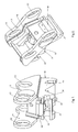
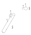
- Figures 1 and 2 illustrate a quick hitch/coupler of a type that is manufactured and marketed by Wedgelock Equipment Limited.
- the coupler is in accordance with conventional construction and includes a body 10 with a pair of upwardly projecting flanges 11 with mounting apertures 13 whereby the coupler 10 can be fixed to the earth working machine e.g. the end of the arm of an excavator.
- the body 10 incorporates a hook portion 14 and a mounting portion 15.
- the coupler includes a locking mechanism. This can be, as illustrated, an hydraulic ram 16 (see Figure 2) mounted within the body 10 and operable to move a wedge 17 (see Figures 12 and 13) so as to lock the back pin of an implement in the mounting portion 15. All of this is in accordance with conventional construction and further description is not required for the purposes of describing the present invention.
- a safety locking device 18 is fitted into the body 10 and, as is more evident in Figure 1, it in part forms the hook portion 14.
- the body 19 of the safety locking device 18 can extend further than illustrated so as to form part of the side plates 20 in the immediate vicinity of the hook portion 14. Such an arrangement can provide manufacturing advantages as well as improve the aesthetic appearance of the safety locking device 18 when incorporated in the quick hitch body 10.
- a safety knuckle 21 Projecting from the body 19 of the safety locking device 18 is a safety knuckle 21. In Figure 1 this is shown in its normal extended position i.e. locking position. It therefore projects downwardly from the body 19 and, as shown in Figure 13, engages with the front pin P so as to lock the front pin P into the hook portion 14.
- the locking knuckle 21 is biased into this projecting position by a spring bias. Therefore, when the front pin P is introduced into the open end of the hook portion 14 it will cause the locking knuckle 21 to move upwardly against the spring bias as the pin P moves into its position fully inserted into the hook portion 14 (see Figure 12). Once it has reached this position the lock knuckle 21 will, under the spring bias, move back to its projecting position (i.e. as shown in Figure 1 3).
- the lock knuckle 21 is mounted on a rotatable shaft 23 (see Figure 4) and is biased by the coil spring 25.
- This coil spring 25 is engaged on the shaft 23.
- One leg 26 of the coil spring 25 engages with a surface 27 of the lock body while the other leg 28 engages against a surface 29 of the knuckle 21.
- the shaft 23 has a bore extended diametrically there through and into which is engaged an engagement element in the form of a lug 30.
- a bolt 31 fixes the lug 30 into place.
- an opening or passage 32 extends through the body 19 so that the lug can be located into the bore when the shaft 23 is in location within the body 19.
- a further passage 33 with blanking off plug 34 screwed therein, is provided in order to enable access to the bolt 31 to be achieved.
- a small linear actuator which can be a single acting hydraulic ram 35.
- the piston 36 of this ram 35 is engageable with the lug 30.
- the hydraulic supply conduit (not shown) which connects at point 35a of the ram 35 is a separate conduit to that which operates the ram of the locking mechanism.
- the hydraulic circuit for the safety locking device is independent of the hydraulic circuit used for operating the ram 16 of quick hitch locking mechanism. As a result of this any failure in the hydraulic circuit e.g. failure of the seal 38 in the piston 36 will have no effect on the locking mechanism of the quick hitch.
- the safety locking device is operated by a switching arrangement which, as shown in Figure 14, is in one preferred form of the invention, a rotary switch 40.
- This switch 40 is formed as part of a control or solenoid driver circuit as shown in Figure 14.
- the solenoid 41 of the quick hitch locking mechanism is coupled to the rotary switch 40. As shown in Figure 14 this circuit includes a visual warning device (e.g. an LCD 42 and a buzzer 43.
- a visual warning device e.g. an LCD 42 and a buzzer 43.
- a solenoid 44 for operation of the safety locking device.
- This circuit includes its own visual indicator such as LCD 45.
- the rotary switch 40 can now be moved to the release position where the implement attached to the hitch can be disengaged i.e. the wedge 17 will be in its retracted position and the safety locking device 18 will be in its open or unlocked position (i.e. knuckle 21 retracted).
- the attachment or implement can therefore be removed from the quick hitch.
- the safety locking device 1 8 is, via the circuitry connected to the latch solenoid 44, able to be "re-set" by one of two different methods.
- the circuitry also provides a time delay which is adjustable in duration of, say, between 4 and 10 seconds. After the elapsed time the timer switches off the power supply to the solenoid 44 allowing the knuckle 21 to rotate into its closed position.
- safety locking device When the safety locking device is reset safety cylinder 35 has no pressure on the piston 36 and the piston is retracted back via the spring 25 acting on the safety knuckle 21 as described above. The hitch is therefore ready for engagement to another attachment or implement.
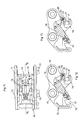
- Figures 15 to 20 graphically illustrate the use of a coupler with an attachment, the coupler incorporating the safety locking device according to the present invention.
- Figure 15 illustrates the coupler C mounted to an excavator arm E in accordance with conventional procedure.
- the coupler C is approaching the attachment (e.g. bucket) A.
- the knuckle 21 is shown in its extended or projecting position.
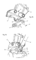
- Figure 16 illustrates the coupler C having engaged with the front pin P and with a locking knuckle 21 engaged over the front pin P so that the pin is locked into the open end of the hook portion 14 of the coupler C.
- Figure 16 shows the coupler having been moved so as to engage with the rear pin P' and the locking wedge 17 extended and locked onto the back pin P' under the hydraulic pressure of the ram 16. The coupler is now engaged with the attachment A and ready for use as normal.
- Figure 18 illustrates the attachment A having been lowered onto a surface and the primary locking wedge 17 disengaged which enables the coupler C to disengage the pack pin P' from the mounting portion 15. It will be noted that the locking knuckle 21 is still engaged with the front pin P so that front pin P cannot be disengaged from the hook portion 14.
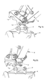
- Figure 19 shows that the lock knuckle 21 has been released thereby enabling the coupler C to be detached from the attachment A.
- Figure 10 shows the coupler C ready to re-connect with the attachment A. It will be noted that the locking knuckle 21 has now reverted to the extended or projecting position and therefore when the coupler C is presented to and engages with the front pin P the locking knuckle will retract then under the spring bias will re-extend to automatically lock the front pin P into position once the pin P has moved into the throat of the hook portion 14.
- the safety device is open to modification.
- the knuckle could be of a sliding construction rather than rotating. It could also have a pivoting action.
- FIG. 21 to 24 illustrates how the lug 30 can be formed with a hook type profile (in cross section) which ensures that the centre line of the piston 36 remains in full contact with the lug 30.
- This modification overcomes any possibility that the piston 36 can slide off the lug 30 especially when the lug 30 is towards the end of its movement as shown in Figure 10.
- Figures 21 and 22 show a further modification that can be made to the locking device.
- Figure 21 shows the knuckle in the raised or retracted position while Figure 22 shows the knuckle extended.
- the present invention thus provides a safety locking device which is operable independent of the hydraulics of the coupler/quick hitch.
- the safety locking device is of a fail safe construction and either via manual re-set or timing out of the circuitry controlling the solenoid 44 will always return to a position whereby it will automatically latch the front pin upon the front pin being inserted into the opening of the hook portion 14 of the quick hitch.
- the present invention differs from other safety systems used with couplers in that with known safety systems the coupler engages with the front pin and the primary lock (e.g. sliding wedge) is engaged and following this the secondary or safety lock is operated. There is thus a period of time when the attachment is engaged with the coupler but the safety lock is not engaged. Thus there is a risk period before the engagement of the safety lock. With the present invention, however, the coupler engages with the front pin and the safety lock device immediately operates and does so before the primary lock (e.g. sliding wedge) is activated. Therefore, there is minimal time between the coupler C coming into engagement with the attachment before the safety lock device becoming effective.
- the primary lock e.g. sliding wedge
Landscapes
- Engineering & Computer Science (AREA)
- Mechanical Engineering (AREA)
- Mining & Mineral Resources (AREA)
- Civil Engineering (AREA)
- General Engineering & Computer Science (AREA)
- Structural Engineering (AREA)
- Shovels (AREA)
- Quick-Acting Or Multi-Walled Pipe Joints (AREA)
- Lock And Its Accessories (AREA)
- Agricultural Machines (AREA)
Priority Applications (2)
| Application Number | Priority Date | Filing Date | Title |
|---|---|---|---|
| EP12000694.5A EP2450490B1 (de) | 2006-05-02 | 2007-05-01 | Sicherheitssperre für eine Schnellkupplung |
| PL07251831T PL1852555T3 (pl) | 2006-05-02 | 2007-05-01 | Zabezpieczające urządzenie blokujące szybkozłącza |
Applications Claiming Priority (2)
| Application Number | Priority Date | Filing Date | Title |
|---|---|---|---|
| NZ54689306A NZ546893A (en) | 2006-05-02 | 2006-05-02 | A safety locking device for a quick hitch/coupler of an earth working machine |
| NZ55229406 | 2006-12-22 |
Related Child Applications (2)
| Application Number | Title | Priority Date | Filing Date |
|---|---|---|---|
| EP12000694.5A Division-Into EP2450490B1 (de) | 2006-05-02 | 2007-05-01 | Sicherheitssperre für eine Schnellkupplung |
| EP12000694.5A Division EP2450490B1 (de) | 2006-05-02 | 2007-05-01 | Sicherheitssperre für eine Schnellkupplung |
Publications (3)
| Publication Number | Publication Date |
|---|---|
| EP1852555A2 true EP1852555A2 (de) | 2007-11-07 |
| EP1852555A3 EP1852555A3 (de) | 2009-07-01 |
| EP1852555B1 EP1852555B1 (de) | 2012-09-12 |
Family
ID=38325274
Family Applications (2)
| Application Number | Title | Priority Date | Filing Date |
|---|---|---|---|
| EP12000694.5A Not-in-force EP2450490B1 (de) | 2006-05-02 | 2007-05-01 | Sicherheitssperre für eine Schnellkupplung |
| EP07251831A Not-in-force EP1852555B1 (de) | 2006-05-02 | 2007-05-01 | Sicherheitsverriegelung für einen Schnellkuppler |
Family Applications Before (1)
| Application Number | Title | Priority Date | Filing Date |
|---|---|---|---|
| EP12000694.5A Not-in-force EP2450490B1 (de) | 2006-05-02 | 2007-05-01 | Sicherheitssperre für eine Schnellkupplung |
Country Status (6)
| Country | Link |
|---|---|
| US (2) | US7828070B2 (de) |
| EP (2) | EP2450490B1 (de) |
| AU (1) | AU2007201982B2 (de) |
| CA (1) | CA2587065C (de) |
| DK (1) | DK1852555T3 (de) |
| PL (1) | PL1852555T3 (de) |
Cited By (15)
| Publication number | Priority date | Publication date | Assignee | Title |
|---|---|---|---|---|
| GB2451304A (en) * | 2007-12-31 | 2009-01-28 | Quick Switch | Hitch safety device |
| GB2466646A (en) * | 2008-12-31 | 2010-07-07 | Quick Switch | Safety System for a Quick Hitch Coupler |
| DE202012009838U1 (de) | 2012-07-24 | 2013-10-25 | Kinshofer Gmbh | Schnellkuppler |
| DE202013004797U1 (de) | 2013-05-23 | 2014-08-25 | Kinshofer Gmbh | Schnellkuppler |
| DE202014004430U1 (de) | 2013-05-31 | 2014-09-02 | Kinshofer Gmbh | Schnellkuppler |
| DE202013005679U1 (de) | 2013-06-24 | 2014-09-25 | Kinshofer Gmbh | Schnellkuppler |
| DE202014001328U1 (de) | 2014-02-13 | 2015-05-15 | Kinshofer Gmbh | Schnellkuppler |
| DE202014010416U1 (de) | 2014-03-31 | 2015-07-27 | Holstein Apparatebau Inh. Eugen Häberle E. Kfm. | Schnellwechselvorrichtung |
| EP2935704A4 (de) * | 2012-12-18 | 2016-08-31 | Jb Attachments Ltd | Koppler |
| DE202016004202U1 (de) | 2016-07-05 | 2017-10-06 | Kinshofer Gmbh | Schnellkuppler |
| DE202017001992U1 (de) | 2017-03-08 | 2018-06-11 | Kinshofer Gmbh | Schnellkuppler |
| DE202019101747U1 (de) | 2019-03-27 | 2020-06-30 | Kinshofer Gmbh | Schnellwechsler für Baumaschinenwerkzeuge |
| EP3770330A1 (de) * | 2019-07-25 | 2021-01-27 | Rädlinger Maschinen- und Stahlbau GmbH | Schnellwechsler |
| DE202021101016U1 (de) | 2020-10-05 | 2022-01-07 | Kinshofer Gmbh | Schnellwechsler für Baumaschinenwerkzeuge |
| WO2023001404A1 (en) * | 2021-07-19 | 2023-01-26 | Caterpillar Sarl | Pin grabber coupler |
Families Citing this family (27)
| Publication number | Priority date | Publication date | Assignee | Title |
|---|---|---|---|---|
| FR2886953B1 (fr) * | 2005-06-14 | 2009-02-06 | Morin Soc Par Actions Simplifi | Support d'articulation pour outils d'engin de travaux, constituant une attache rapide ou une partie de l'outil et procede de fabrication associe |
| EP2450490B1 (de) * | 2006-05-02 | 2018-04-04 | Kinshofer GmbH | Sicherheitssperre für eine Schnellkupplung |
| US8011121B2 (en) * | 2008-08-07 | 2011-09-06 | Paladin Brands Group, Inc. | Spread-style coupler with supplemental safety lock |
| GB2464988B8 (en) * | 2008-11-03 | 2013-02-20 | Miller Int Ltd | Coupler with coupling status sensors |
| US8262310B2 (en) * | 2008-11-20 | 2012-09-11 | Paladin Brands Group, Inc. | Coupler with secondary lock on front hook |
| US8662817B2 (en) * | 2009-01-08 | 2014-03-04 | Paladin Brands Group, Inc. | Coupler with safety cam |
| US8585345B2 (en) | 2010-03-26 | 2013-11-19 | Paladin Brands Group, Inc. | Coupler with pivoting front hook lock |
| CA2817625A1 (en) * | 2010-11-12 | 2012-05-18 | Positti, Nicole Elizabeth | A hydraulic hitch assembly |
| SE536061C2 (sv) * | 2011-09-15 | 2013-04-23 | Steelwrist Ab | Framaxellåsning för redskapsfäste |
| US8974137B2 (en) | 2011-12-22 | 2015-03-10 | Caterpillar Inc. | Quick coupler |
| US9217235B2 (en) | 2012-05-30 | 2015-12-22 | Caterpillar Inc. | Tool coupler system having multiple pressure sources |
| US8869437B2 (en) | 2012-05-30 | 2014-10-28 | Caterpillar Inc. | Quick coupler |
| US8684623B2 (en) | 2012-05-30 | 2014-04-01 | Caterpillar Inc. | Tool coupler having anti-release mechanism |
| US9228314B2 (en) | 2013-05-08 | 2016-01-05 | Caterpillar Inc. | Quick coupler hydraulic control system |
| US9455076B2 (en) | 2014-02-21 | 2016-09-27 | Magnet-Schultz Of America, Inc. | Coupling with solenoid release locking mechanism |
| KR102241176B1 (ko) * | 2014-04-10 | 2021-04-16 | 두산인프라코어 주식회사 | 굴삭기의 퀵 커플러 제어 방법 및 이를 수행하기 위한 장치 |
| CH710006A1 (de) * | 2014-08-20 | 2016-02-29 | Josef Martin Gmbh | Schnellwechselkupplung zum Ankuppeln eines Anbaugeräts an einem Baggerarm. |
| DE102014116245B4 (de) | 2014-11-07 | 2016-11-10 | Bela Cseri | Schnellwechseleinrichtung einer Arbeitsmaschine |
| US9903095B2 (en) * | 2015-01-30 | 2018-02-27 | Caterpillar Inc. | Tool coupler |
| WO2017079792A1 (en) * | 2015-11-09 | 2017-05-18 | Elite Attachments Australia Pty Ltd | A piston and cylinder system |
| USD805368S1 (en) * | 2016-12-22 | 2017-12-19 | Jian Jiang Gui | Magnetic drawer lock |
| WO2019026031A1 (en) * | 2017-08-04 | 2019-02-07 | Wedgelock Equipment Limited | QUICK COUPLING |
| CN109853653B (zh) * | 2018-12-11 | 2023-04-28 | 徐州徐工特种工程机械有限公司 | 一种属具快换装置 |
| US11053660B2 (en) | 2019-06-17 | 2021-07-06 | Caterpillar Inc. | Coupling assembly and method of hydraulically coupling to a tool |
| WO2021084482A1 (en) * | 2019-11-01 | 2021-05-06 | Wedgelock Equipment Limited | A packer |
| US11702816B2 (en) | 2020-01-30 | 2023-07-18 | Wedgelock Equipment Limited | Quick coupler |
| DE202020100794U1 (de) * | 2020-02-14 | 2021-05-17 | Kinshofer Gmbh | Hydraulisches Anbaugerät sowie Baumaschine mit einem solchen Anbaugerät |
Citations (8)
| Publication number | Priority date | Publication date | Assignee | Title |
|---|---|---|---|---|
| EP0405813A2 (de) * | 1989-06-29 | 1991-01-02 | Steelfab Limited | Vorrichtung zum Befestigen eines Arbeitsgerätes |
| US5082389A (en) * | 1987-06-04 | 1992-01-21 | Balemi William J | Connector with a spring-biased closure member |
| US6154989A (en) * | 1997-03-10 | 2000-12-05 | Clark Equipment Company | Attachment construction for earthworking implement |
| US6301811B1 (en) * | 2000-07-28 | 2001-10-16 | Gilmore Industries, Inc. | Coupler for a heavy-duty machine |
| DE20119092U1 (de) * | 2001-11-22 | 2002-01-31 | Nagler Juergen | Befestigungsvorrichtung für Arbeitswerkzeuge an Hydraulikbaggern |
| WO2004038110A1 (en) * | 2002-10-24 | 2004-05-06 | Bruce Archibald Short | Connector for earth moving implements |
| EP1477615A1 (de) * | 2003-05-13 | 2004-11-17 | Ateliers de Construction du Beaujolais | Vorrichtung zur Kupplung eines Werkzeugs an eine Auslegerspitze einer Maschine, sowie einen hydraulischen Bagger. |
| WO2005026454A1 (en) * | 2003-09-18 | 2005-03-24 | Patrick Mccormick | An excavator tool quick attachment device |
Family Cites Families (36)
| Publication number | Priority date | Publication date | Assignee | Title |
|---|---|---|---|---|
| US3511316A (en) * | 1967-01-05 | 1970-05-12 | Deere & Co | Hydraulic marker for agricultural implements |
| US3587750A (en) * | 1969-01-27 | 1971-06-28 | Deere & Co | Row marker |
| AT338021B (de) * | 1975-03-11 | 1977-07-25 | Walterscheid Gmbh Jean | Kupplungshaken, insbesondere fur ein dreipunktgestange eines schleppers |
| US4624196A (en) * | 1985-08-09 | 1986-11-25 | Anderson Edwin V | Combined seed drill and fertilizer applicator |
| DE3912414C1 (de) * | 1989-04-15 | 1990-06-13 | Jean Walterscheid Gmbh, 5204 Lohmar, De | |
| NZ233302A (en) | 1990-04-11 | 1994-05-26 | Calvert Leonard Graham Substit | Quick hitch lock mechanism for excavator bucket |
| US5048274A (en) * | 1990-06-15 | 1991-09-17 | Ford New Holland, Inc. | Apparatus and method for controlling multiple functions of an agricultural implement |
| US5147173A (en) * | 1991-06-03 | 1992-09-15 | Caterpillar Inc. | Coupling device |
| US5244047A (en) * | 1991-08-05 | 1993-09-14 | Arthur H. Groover | Apparatus for coupling implements to a farm tractor |
| US5179794A (en) * | 1991-12-26 | 1993-01-19 | Ballinger Jon C | Semi-automatic coupling apparatus |
| NZ260659A (en) | 1994-06-01 | 1996-10-28 | Leonard Graham Calvert | Quick coupling lock mechanism for excavator bucket hitch |
| US5727342A (en) * | 1996-04-18 | 1998-03-17 | Wain-Roy, Inc. | Hydraulic latch pin assembly for coupling a tool to a construction equipment |
| JPH1082066A (ja) * | 1996-09-05 | 1998-03-31 | Marujiyun Juko Kk | 土工機械のアタッチメント連結カプラ |
| US6163989A (en) * | 1997-03-10 | 2000-12-26 | Clark Equipment Company | Frame for mounting on a boom mounted quick change bracket |
| JP3056706B2 (ja) * | 1997-10-07 | 2000-06-26 | 新キャタピラー三菱株式会社 | 作業機械のアタッチメント着脱装置 |
| US6058633A (en) * | 1997-10-22 | 2000-05-09 | Barden; William Mark | Quick coupling device and method utilizing an over-center spring |
| US5890871A (en) * | 1997-12-10 | 1999-04-06 | Caterpillar Inc. | Latching mechanism for a quick coupler |
| US6139212A (en) * | 1998-02-11 | 2000-10-31 | Rockland Manufacturing Co. | Coupler for excavating machines and the like having fixed and moveable jaws |
| GB2330569B (en) | 1998-09-08 | 1999-09-15 | Miller Ronald Keith | Coupler for bucket excavators |
| GB2330570B (en) * | 1998-09-08 | 1999-09-15 | Miller Ronald Keith | Quick coupler for bucket excavators |
| US6254331B1 (en) * | 1999-02-04 | 2001-07-03 | Pacific Services & Mfg. | Coupler for connecting an attachment to the free end of a boom |
| KR100321009B1 (ko) * | 1999-08-30 | 2002-01-18 | 구영근 | 굴삭기 어태치먼트 장착용 유압클램프 |
| US6379075B1 (en) * | 2000-01-18 | 2002-04-30 | Gh Hensley Industries, Inc. | Quick coupler apparatus |
| GB2359062B (en) * | 2000-02-11 | 2002-01-02 | Ronald Keith Miller | Universal coupler for bucket excavators |
| US6699001B2 (en) * | 2000-12-11 | 2004-03-02 | Jrb Company, Inc. | Coupler with improved pin lock |
| US6691438B2 (en) * | 2001-04-26 | 2004-02-17 | Jrb Company, Inc. | Coupler with improved structure and method for manufacturing same |
| ATE342406T1 (de) | 2001-12-06 | 2006-11-15 | Geith Patents Ltd | Werkzeugschnellkupplung zum kuppeln eines anbauteils an einen baggerarm und die werkzeugschnellkupplung umfassend ein steuerungssystem |
| US6902346B2 (en) * | 2002-03-15 | 2005-06-07 | Hendrix Manufacturing, Ltd. | Hydraulic coupler |
| US7047866B2 (en) * | 2003-01-31 | 2006-05-23 | Jrb Attachments, Llc | Electrical and hydraulic control system for attachment coupling system |
| US7367256B2 (en) * | 2003-01-31 | 2008-05-06 | Jrb Attachments, Llc | Pressure switch control for attachment coupling system |
| US7473607B2 (en) * | 2005-07-06 | 2009-01-06 | International Business Machines Corporation | Method of manufacturing a multi-workfunction gates for a CMOS circuit |
| US7530405B2 (en) * | 2005-09-09 | 2009-05-12 | Deere & Company | Implement quick coupler latch mechanism |
| NZ569184A (en) * | 2005-12-12 | 2011-12-22 | Stuart Alexander Essex | Safety device with engaged and disengaged positions by hydraulic piston for hydraulic hitch assembly |
| EP2450490B1 (de) * | 2006-05-02 | 2018-04-04 | Kinshofer GmbH | Sicherheitssperre für eine Schnellkupplung |
| US7690439B2 (en) * | 2006-12-14 | 2010-04-06 | Cnh America Llc | Automatic latch for three point hitch quick coupler and PTO connection module |
| US7648305B2 (en) * | 2007-02-08 | 2010-01-19 | Cws Industries (Mfg.) Corp. | Pin grabber coupler |
-
2007
- 2007-05-01 EP EP12000694.5A patent/EP2450490B1/de not_active Not-in-force
- 2007-05-01 EP EP07251831A patent/EP1852555B1/de not_active Not-in-force
- 2007-05-01 DK DK07251831.9T patent/DK1852555T3/da active
- 2007-05-01 PL PL07251831T patent/PL1852555T3/pl unknown
- 2007-05-02 US US11/797,266 patent/US7828070B2/en active Active
- 2007-05-02 CA CA2587065A patent/CA2587065C/en active Active
- 2007-05-02 AU AU2007201982A patent/AU2007201982B2/en active Active
-
2010
- 2010-09-28 US US12/892,023 patent/US8347974B2/en active Active
Patent Citations (8)
| Publication number | Priority date | Publication date | Assignee | Title |
|---|---|---|---|---|
| US5082389A (en) * | 1987-06-04 | 1992-01-21 | Balemi William J | Connector with a spring-biased closure member |
| EP0405813A2 (de) * | 1989-06-29 | 1991-01-02 | Steelfab Limited | Vorrichtung zum Befestigen eines Arbeitsgerätes |
| US6154989A (en) * | 1997-03-10 | 2000-12-05 | Clark Equipment Company | Attachment construction for earthworking implement |
| US6301811B1 (en) * | 2000-07-28 | 2001-10-16 | Gilmore Industries, Inc. | Coupler for a heavy-duty machine |
| DE20119092U1 (de) * | 2001-11-22 | 2002-01-31 | Nagler Juergen | Befestigungsvorrichtung für Arbeitswerkzeuge an Hydraulikbaggern |
| WO2004038110A1 (en) * | 2002-10-24 | 2004-05-06 | Bruce Archibald Short | Connector for earth moving implements |
| EP1477615A1 (de) * | 2003-05-13 | 2004-11-17 | Ateliers de Construction du Beaujolais | Vorrichtung zur Kupplung eines Werkzeugs an eine Auslegerspitze einer Maschine, sowie einen hydraulischen Bagger. |
| WO2005026454A1 (en) * | 2003-09-18 | 2005-03-24 | Patrick Mccormick | An excavator tool quick attachment device |
Cited By (28)
| Publication number | Priority date | Publication date | Assignee | Title |
|---|---|---|---|---|
| GB2451304A (en) * | 2007-12-31 | 2009-01-28 | Quick Switch | Hitch safety device |
| GB2451304B (en) * | 2007-12-31 | 2009-11-18 | Quick Switch | Quick Hitch |
| GB2466646A (en) * | 2008-12-31 | 2010-07-07 | Quick Switch | Safety System for a Quick Hitch Coupler |
| DE202012009838U1 (de) | 2012-07-24 | 2013-10-25 | Kinshofer Gmbh | Schnellkuppler |
| EP2690223A2 (de) | 2012-07-24 | 2014-01-29 | Kinshofer GmbH | Schnellkuppler für eine Baumaschine |
| EP2935704A4 (de) * | 2012-12-18 | 2016-08-31 | Jb Attachments Ltd | Koppler |
| DE202013004797U1 (de) | 2013-05-23 | 2014-08-25 | Kinshofer Gmbh | Schnellkuppler |
| DE202014004430U1 (de) | 2013-05-31 | 2014-09-02 | Kinshofer Gmbh | Schnellkuppler |
| US9834904B2 (en) | 2013-05-31 | 2017-12-05 | Kinshofer Gmbh | Quick-coupler |
| GB2517831A (en) * | 2013-06-24 | 2015-03-04 | Kinshofer Greiftechnik | Quick-coupler |
| DE202013005679U1 (de) | 2013-06-24 | 2014-09-25 | Kinshofer Gmbh | Schnellkuppler |
| US9388549B2 (en) | 2013-06-24 | 2016-07-12 | Kinshofer Gmbh | Quick-coupler |
| GB2517831B (en) * | 2013-06-24 | 2016-08-03 | Kinshofer Greiftechnik | Quick-coupler |
| US9689139B2 (en) | 2014-02-13 | 2017-06-27 | Kinshofer Gmbh | Quick coupler |
| DE202014001328U1 (de) | 2014-02-13 | 2015-05-15 | Kinshofer Gmbh | Schnellkuppler |
| DE202014010416U1 (de) | 2014-03-31 | 2015-07-27 | Holstein Apparatebau Inh. Eugen Häberle E. Kfm. | Schnellwechselvorrichtung |
| EP3266940B1 (de) * | 2016-07-05 | 2020-09-30 | Kinshofer GmbH | Schnellkuppler |
| DE202016004202U1 (de) | 2016-07-05 | 2017-10-06 | Kinshofer Gmbh | Schnellkuppler |
| EP3266940A1 (de) | 2016-07-05 | 2018-01-10 | Kinshofer GmbH | Schnellkuppler |
| US10323379B2 (en) | 2016-07-05 | 2019-06-18 | Kinshofer Gmbh | Quick coupler with independent locking element and securing element |
| DE202017001992U1 (de) | 2017-03-08 | 2018-06-11 | Kinshofer Gmbh | Schnellkuppler |
| DE202019101747U1 (de) | 2019-03-27 | 2020-06-30 | Kinshofer Gmbh | Schnellwechsler für Baumaschinenwerkzeuge |
| EP3715535A1 (de) | 2019-03-27 | 2020-09-30 | Kinshofer GmbH | Schnellwechsler für baumaschinenwerkzeuge |
| US11441290B2 (en) | 2019-03-27 | 2022-09-13 | Kinshofer Gmbh | Quick-hitch for construction vehicle tools |
| EP3770330A1 (de) * | 2019-07-25 | 2021-01-27 | Rädlinger Maschinen- und Stahlbau GmbH | Schnellwechsler |
| DE202021101016U1 (de) | 2020-10-05 | 2022-01-07 | Kinshofer Gmbh | Schnellwechsler für Baumaschinenwerkzeuge |
| WO2023001404A1 (en) * | 2021-07-19 | 2023-01-26 | Caterpillar Sarl | Pin grabber coupler |
| US11773562B2 (en) | 2021-07-19 | 2023-10-03 | Caterpillar Sarl | Pin grabber coupler |
Also Published As
| Publication number | Publication date |
|---|---|
| CA2587065C (en) | 2014-08-26 |
| PL1852555T3 (pl) | 2013-01-31 |
| EP2450490A1 (de) | 2012-05-09 |
| DK1852555T3 (da) | 2012-10-08 |
| US8347974B2 (en) | 2013-01-08 |
| US20080067784A1 (en) | 2008-03-20 |
| US7828070B2 (en) | 2010-11-09 |
| CA2587065A1 (en) | 2007-11-02 |
| EP1852555A3 (de) | 2009-07-01 |
| US20110010915A1 (en) | 2011-01-20 |
| EP1852555B1 (de) | 2012-09-12 |
| CA2587065E (en) | 2007-11-02 |
| EP2450490B1 (de) | 2018-04-04 |
| AU2007201982B2 (en) | 2015-06-18 |
| AU2007201982A1 (en) | 2007-11-22 |
Similar Documents
| Publication | Publication Date | Title |
|---|---|---|
| EP1852555B1 (de) | Sicherheitsverriegelung für einen Schnellkuppler | |
| AU2016236860B2 (en) | A visual indicator for a coupler | |
| AU2016225818B2 (en) | Improvements relating to Couplers | |
| US6964122B2 (en) | Coupler for coupling an accessory to a dipper arm and a control system for such a coupler | |
| US6699001B2 (en) | Coupler with improved pin lock | |
| NZ546893A (en) | A safety locking device for a quick hitch/coupler of an earth working machine | |
| US20220034061A1 (en) | I-lock coupler | |
| AU723305B1 (en) | Adaptor hitch with locking pin | |
| AU2018100857A4 (en) | Coupling device |
Legal Events
| Date | Code | Title | Description |
|---|---|---|---|
| PUAI | Public reference made under article 153(3) epc to a published international application that has entered the european phase |
Free format text: ORIGINAL CODE: 0009012 |
|
| AK | Designated contracting states |
Kind code of ref document: A2 Designated state(s): AT BE BG CH CY CZ DE DK EE ES FI FR GB GR HU IE IS IT LI LT LU LV MC MT NL PL PT RO SE SI SK TR |
|
| AX | Request for extension of the european patent |
Extension state: AL BA HR MK YU |
|
| PUAL | Search report despatched |
Free format text: ORIGINAL CODE: 0009013 |
|
| AK | Designated contracting states |
Kind code of ref document: A3 Designated state(s): AT BE BG CH CY CZ DE DK EE ES FI FR GB GR HU IE IS IT LI LT LU LV MC MT NL PL PT RO SE SI SK TR |
|
| AX | Request for extension of the european patent |
Extension state: AL BA HR MK RS |
|
| 17P | Request for examination filed |
Effective date: 20091231 |
|
| 17Q | First examination report despatched |
Effective date: 20100202 |
|
| AKX | Designation fees paid |
Designated state(s): AT BE BG CH CY CZ DE DK EE ES FI FR GB GR HU IE IS IT LI LT LU LV MC MT NL PL PT RO SE SI SK TR |
|
| GRAP | Despatch of communication of intention to grant a patent |
Free format text: ORIGINAL CODE: EPIDOSNIGR1 |
|
| RAP1 | Party data changed (applicant data changed or rights of an application transferred) |
Owner name: KINSHOFER GMBH |
|
| GRAS | Grant fee paid |
Free format text: ORIGINAL CODE: EPIDOSNIGR3 |
|
| GRAA | (expected) grant |
Free format text: ORIGINAL CODE: 0009210 |
|
| AK | Designated contracting states |
Kind code of ref document: B1 Designated state(s): AT BE BG CH CY CZ DE DK EE ES FI FR GB GR HU IE IS IT LI LT LU LV MC MT NL PL PT RO SE SI SK TR |
|
| REG | Reference to a national code |
Ref country code: GB Ref legal event code: FG4D |
|
| REG | Reference to a national code |
Ref country code: CH Ref legal event code: EP |
|
| REG | Reference to a national code |
Ref country code: AT Ref legal event code: REF Ref document number: 575175 Country of ref document: AT Kind code of ref document: T Effective date: 20120915 |
|
| REG | Reference to a national code |
Ref country code: DK Ref legal event code: T3 |
|
| REG | Reference to a national code |
Ref country code: IE Ref legal event code: FG4D |
|
| REG | Reference to a national code |
Ref country code: SE Ref legal event code: TRGR |
|
| REG | Reference to a national code |
Ref country code: DE Ref legal event code: R096 Ref document number: 602007025392 Country of ref document: DE Effective date: 20121108 |
|
| REG | Reference to a national code |
Ref country code: NL Ref legal event code: T3 |
|
| PG25 | Lapsed in a contracting state [announced via postgrant information from national office to epo] |
Ref country code: CY Free format text: LAPSE BECAUSE OF FAILURE TO SUBMIT A TRANSLATION OF THE DESCRIPTION OR TO PAY THE FEE WITHIN THE PRESCRIBED TIME-LIMIT Effective date: 20120912 Ref country code: LT Free format text: LAPSE BECAUSE OF FAILURE TO SUBMIT A TRANSLATION OF THE DESCRIPTION OR TO PAY THE FEE WITHIN THE PRESCRIBED TIME-LIMIT Effective date: 20120912 |
|
| REG | Reference to a national code |
Ref country code: PL Ref legal event code: T3 |
|
| REG | Reference to a national code |
Ref country code: LT Ref legal event code: MG4D Effective date: 20120912 |
|
| PG25 | Lapsed in a contracting state [announced via postgrant information from national office to epo] |
Ref country code: LV Free format text: LAPSE BECAUSE OF FAILURE TO SUBMIT A TRANSLATION OF THE DESCRIPTION OR TO PAY THE FEE WITHIN THE PRESCRIBED TIME-LIMIT Effective date: 20120912 Ref country code: GR Free format text: LAPSE BECAUSE OF FAILURE TO SUBMIT A TRANSLATION OF THE DESCRIPTION OR TO PAY THE FEE WITHIN THE PRESCRIBED TIME-LIMIT Effective date: 20121213 Ref country code: SI Free format text: LAPSE BECAUSE OF FAILURE TO SUBMIT A TRANSLATION OF THE DESCRIPTION OR TO PAY THE FEE WITHIN THE PRESCRIBED TIME-LIMIT Effective date: 20120912 |
|
| PG25 | Lapsed in a contracting state [announced via postgrant information from national office to epo] |
Ref country code: ES Free format text: LAPSE BECAUSE OF FAILURE TO SUBMIT A TRANSLATION OF THE DESCRIPTION OR TO PAY THE FEE WITHIN THE PRESCRIBED TIME-LIMIT Effective date: 20121223 Ref country code: EE Free format text: LAPSE BECAUSE OF FAILURE TO SUBMIT A TRANSLATION OF THE DESCRIPTION OR TO PAY THE FEE WITHIN THE PRESCRIBED TIME-LIMIT Effective date: 20120912 Ref country code: IS Free format text: LAPSE BECAUSE OF FAILURE TO SUBMIT A TRANSLATION OF THE DESCRIPTION OR TO PAY THE FEE WITHIN THE PRESCRIBED TIME-LIMIT Effective date: 20130112 Ref country code: RO Free format text: LAPSE BECAUSE OF FAILURE TO SUBMIT A TRANSLATION OF THE DESCRIPTION OR TO PAY THE FEE WITHIN THE PRESCRIBED TIME-LIMIT Effective date: 20120912 |
|
| PG25 | Lapsed in a contracting state [announced via postgrant information from national office to epo] |
Ref country code: PT Free format text: LAPSE BECAUSE OF FAILURE TO SUBMIT A TRANSLATION OF THE DESCRIPTION OR TO PAY THE FEE WITHIN THE PRESCRIBED TIME-LIMIT Effective date: 20130114 Ref country code: SK Free format text: LAPSE BECAUSE OF FAILURE TO SUBMIT A TRANSLATION OF THE DESCRIPTION OR TO PAY THE FEE WITHIN THE PRESCRIBED TIME-LIMIT Effective date: 20120912 |
|
| PLBE | No opposition filed within time limit |
Free format text: ORIGINAL CODE: 0009261 |
|
| STAA | Information on the status of an ep patent application or granted ep patent |
Free format text: STATUS: NO OPPOSITION FILED WITHIN TIME LIMIT |
|
| PG25 | Lapsed in a contracting state [announced via postgrant information from national office to epo] |
Ref country code: BG Free format text: LAPSE BECAUSE OF FAILURE TO SUBMIT A TRANSLATION OF THE DESCRIPTION OR TO PAY THE FEE WITHIN THE PRESCRIBED TIME-LIMIT Effective date: 20121212 |
|
| 26N | No opposition filed |
Effective date: 20130613 |
|
| PG25 | Lapsed in a contracting state [announced via postgrant information from national office to epo] |
Ref country code: IT Free format text: LAPSE BECAUSE OF FAILURE TO SUBMIT A TRANSLATION OF THE DESCRIPTION OR TO PAY THE FEE WITHIN THE PRESCRIBED TIME-LIMIT Effective date: 20120912 |
|
| PGFP | Annual fee paid to national office [announced via postgrant information from national office to epo] |
Ref country code: TR Payment date: 20130430 Year of fee payment: 7 |
|
| REG | Reference to a national code |
Ref country code: DE Ref legal event code: R097 Ref document number: 602007025392 Country of ref document: DE Effective date: 20130613 |
|
| BERE | Be: lapsed |
Owner name: KINSHOFER G.M.B.H. Effective date: 20130531 |
|
| REG | Reference to a national code |
Ref country code: NL Ref legal event code: V1 Effective date: 20131201 |
|
| PG25 | Lapsed in a contracting state [announced via postgrant information from national office to epo] |
Ref country code: MC Free format text: LAPSE BECAUSE OF FAILURE TO SUBMIT A TRANSLATION OF THE DESCRIPTION OR TO PAY THE FEE WITHIN THE PRESCRIBED TIME-LIMIT Effective date: 20120912 |
|
| REG | Reference to a national code |
Ref country code: CH Ref legal event code: PL |
|
| PG25 | Lapsed in a contracting state [announced via postgrant information from national office to epo] |
Ref country code: CZ Free format text: LAPSE BECAUSE OF NON-PAYMENT OF DUE FEES Effective date: 20130501 Ref country code: CH Free format text: LAPSE BECAUSE OF NON-PAYMENT OF DUE FEES Effective date: 20130531 Ref country code: LI Free format text: LAPSE BECAUSE OF NON-PAYMENT OF DUE FEES Effective date: 20130531 |
|
| REG | Reference to a national code |
Ref country code: DK Ref legal event code: EBP Effective date: 20130531 |
|
| REG | Reference to a national code |
Ref country code: IE Ref legal event code: MM4A |
|
| PG25 | Lapsed in a contracting state [announced via postgrant information from national office to epo] |
Ref country code: NL Free format text: LAPSE BECAUSE OF NON-PAYMENT OF DUE FEES Effective date: 20131201 Ref country code: BE Free format text: LAPSE BECAUSE OF NON-PAYMENT OF DUE FEES Effective date: 20130531 Ref country code: FI Free format text: LAPSE BECAUSE OF NON-PAYMENT OF DUE FEES Effective date: 20130501 |
|
| PG25 | Lapsed in a contracting state [announced via postgrant information from national office to epo] |
Ref country code: DK Free format text: LAPSE BECAUSE OF NON-PAYMENT OF DUE FEES Effective date: 20130531 Ref country code: IE Free format text: LAPSE BECAUSE OF NON-PAYMENT OF DUE FEES Effective date: 20130501 |
|
| PG25 | Lapsed in a contracting state [announced via postgrant information from national office to epo] |
Ref country code: PL Free format text: LAPSE BECAUSE OF NON-PAYMENT OF DUE FEES Effective date: 20130501 |
|
| REG | Reference to a national code |
Ref country code: PL Ref legal event code: LAPE |
|
| PG25 | Lapsed in a contracting state [announced via postgrant information from national office to epo] |
Ref country code: MT Free format text: LAPSE BECAUSE OF FAILURE TO SUBMIT A TRANSLATION OF THE DESCRIPTION OR TO PAY THE FEE WITHIN THE PRESCRIBED TIME-LIMIT Effective date: 20120912 |
|
| PG25 | Lapsed in a contracting state [announced via postgrant information from national office to epo] |
Ref country code: LU Free format text: LAPSE BECAUSE OF NON-PAYMENT OF DUE FEES Effective date: 20130501 Ref country code: HU Free format text: LAPSE BECAUSE OF FAILURE TO SUBMIT A TRANSLATION OF THE DESCRIPTION OR TO PAY THE FEE WITHIN THE PRESCRIBED TIME-LIMIT; INVALID AB INITIO Effective date: 20070501 |
|
| REG | Reference to a national code |
Ref country code: FR Ref legal event code: PLFP Year of fee payment: 10 |
|
| REG | Reference to a national code |
Ref country code: FR Ref legal event code: PLFP Year of fee payment: 11 |
|
| PG25 | Lapsed in a contracting state [announced via postgrant information from national office to epo] |
Ref country code: TR Free format text: LAPSE BECAUSE OF NON-PAYMENT OF DUE FEES Effective date: 20140501 |
|
| PGFP | Annual fee paid to national office [announced via postgrant information from national office to epo] |
Ref country code: IT Payment date: 20170421 Year of fee payment: 11 |
|
| REG | Reference to a national code |
Ref country code: FR Ref legal event code: PLFP Year of fee payment: 12 |
|
| REG | Reference to a national code |
Ref country code: AT Ref legal event code: MM01 Ref document number: 575175 Country of ref document: AT Kind code of ref document: T Effective date: 20180501 |
|
| PG25 | Lapsed in a contracting state [announced via postgrant information from national office to epo] |
Ref country code: AT Free format text: LAPSE BECAUSE OF NON-PAYMENT OF DUE FEES Effective date: 20180501 |
|
| PGFP | Annual fee paid to national office [announced via postgrant information from national office to epo] |
Ref country code: SE Payment date: 20190524 Year of fee payment: 13 Ref country code: FR Payment date: 20190524 Year of fee payment: 13 |
|
| PG25 | Lapsed in a contracting state [announced via postgrant information from national office to epo] |
Ref country code: SE Free format text: LAPSE BECAUSE OF NON-PAYMENT OF DUE FEES Effective date: 20200502 |
|
| PG25 | Lapsed in a contracting state [announced via postgrant information from national office to epo] |
Ref country code: FR Free format text: LAPSE BECAUSE OF NON-PAYMENT OF DUE FEES Effective date: 20200531 |
|
| PGFP | Annual fee paid to national office [announced via postgrant information from national office to epo] |
Ref country code: DE Payment date: 20210531 Year of fee payment: 15 |
|
| PGFP | Annual fee paid to national office [announced via postgrant information from national office to epo] |
Ref country code: GB Payment date: 20210522 Year of fee payment: 15 |
|
| REG | Reference to a national code |
Ref country code: DE Ref legal event code: R119 Ref document number: 602007025392 Country of ref document: DE |
|
| GBPC | Gb: european patent ceased through non-payment of renewal fee |
Effective date: 20220501 |
|
| PG25 | Lapsed in a contracting state [announced via postgrant information from national office to epo] |
Ref country code: GB Free format text: LAPSE BECAUSE OF NON-PAYMENT OF DUE FEES Effective date: 20220501 Ref country code: DE Free format text: LAPSE BECAUSE OF NON-PAYMENT OF DUE FEES Effective date: 20221201 |