EP1849955A1 - Drehschlagbohrer mit viergängigem Bohrwendelschaft - Google Patents
Drehschlagbohrer mit viergängigem Bohrwendelschaft Download PDFInfo
- Publication number
- EP1849955A1 EP1849955A1 EP07106506A EP07106506A EP1849955A1 EP 1849955 A1 EP1849955 A1 EP 1849955A1 EP 07106506 A EP07106506 A EP 07106506A EP 07106506 A EP07106506 A EP 07106506A EP 1849955 A1 EP1849955 A1 EP 1849955A1
- Authority
- EP
- European Patent Office
- Prior art keywords
- helical
- section
- rotary impact
- edge
- drill according
- Prior art date
- Legal status (The legal status is an assumption and is not a legal conclusion. Google has not performed a legal analysis and makes no representation as to the accuracy of the status listed.)
- Granted
Links
Images
Classifications
-
- E—FIXED CONSTRUCTIONS
- E21—EARTH OR ROCK DRILLING; MINING
- E21B—EARTH OR ROCK DRILLING; OBTAINING OIL, GAS, WATER, SOLUBLE OR MELTABLE MATERIALS OR A SLURRY OF MINERALS FROM WELLS
- E21B10/00—Drill bits
- E21B10/44—Bits with helical conveying portion, e.g. screw type bits; Augers with leading portion or with detachable parts
- E21B10/445—Bits with helical conveying portion, e.g. screw type bits; Augers with leading portion or with detachable parts percussion type, e.g. for masonry
-
- B—PERFORMING OPERATIONS; TRANSPORTING
- B23—MACHINE TOOLS; METAL-WORKING NOT OTHERWISE PROVIDED FOR
- B23B—TURNING; BORING
- B23B51/00—Tools for drilling machines
- B23B51/02—Twist drills
-
- B—PERFORMING OPERATIONS; TRANSPORTING
- B23—MACHINE TOOLS; METAL-WORKING NOT OTHERWISE PROVIDED FOR
- B23B—TURNING; BORING
- B23B2226/00—Materials of tools or workpieces not comprising a metal
- B23B2226/75—Stone, rock or concrete
-
- B—PERFORMING OPERATIONS; TRANSPORTING
- B23—MACHINE TOOLS; METAL-WORKING NOT OTHERWISE PROVIDED FOR
- B23B—TURNING; BORING
- B23B2251/00—Details of tools for drilling machines
- B23B2251/14—Configuration of the cutting part, i.e. the main cutting edges
-
- B—PERFORMING OPERATIONS; TRANSPORTING
- B23—MACHINE TOOLS; METAL-WORKING NOT OTHERWISE PROVIDED FOR
- B23B—TURNING; BORING
- B23B2251/00—Details of tools for drilling machines
- B23B2251/20—Number of cutting edges
- B23B2251/204—Four cutting edges
-
- B—PERFORMING OPERATIONS; TRANSPORTING
- B23—MACHINE TOOLS; METAL-WORKING NOT OTHERWISE PROVIDED FOR
- B23B—TURNING; BORING
- B23B2251/00—Details of tools for drilling machines
- B23B2251/40—Flutes, i.e. chip conveying grooves
- B23B2251/406—Flutes, i.e. chip conveying grooves of special form not otherwise provided for
-
- B—PERFORMING OPERATIONS; TRANSPORTING
- B23—MACHINE TOOLS; METAL-WORKING NOT OTHERWISE PROVIDED FOR
- B23B—TURNING; BORING
- B23B2251/00—Details of tools for drilling machines
- B23B2251/50—Drilling tools comprising cutting inserts
-
- Y—GENERAL TAGGING OF NEW TECHNOLOGICAL DEVELOPMENTS; GENERAL TAGGING OF CROSS-SECTIONAL TECHNOLOGIES SPANNING OVER SEVERAL SECTIONS OF THE IPC; TECHNICAL SUBJECTS COVERED BY FORMER USPC CROSS-REFERENCE ART COLLECTIONS [XRACs] AND DIGESTS
- Y10—TECHNICAL SUBJECTS COVERED BY FORMER USPC
- Y10T—TECHNICAL SUBJECTS COVERED BY FORMER US CLASSIFICATION
- Y10T408/00—Cutting by use of rotating axially moving tool
- Y10T408/89—Tool or Tool with support
- Y10T408/909—Having peripherally spaced cutting edges
- Y10T408/9095—Having peripherally spaced cutting edges with axially extending relief channel
- Y10T408/9097—Spiral channel
Definitions
- the invention refers to a rotary impact drill for rock, preferably in the diameter range of 3 mm to 45 mm for use in rotary impact power hand tools, with a four-speed Bohrchtlschaft.
- BohrwendelWarfte of rotary impact drills usually form in Wendelquerrough a shame Ichindelquerrough a provoke Ichindelquerrough a provoke Ichindelquerrough a provoke Ichndelquerrough a provoke Ichndelquerrough a provoke Ichndelquerrough a provoke Ichndelquerrough a provoke Ichndelquerrough a provoke Ichndelquerrough a provoke Ichndelquerrough a provoke Ichndelquerites a provoke the individual spiral webs projecting radially from the concavely-shaped groove bottom taper radially outwards, or after US2673716 stay the same width.
- DE2895355 is a four-turn helical shank of a boring bar with a helical cross section with administratedr rotation and mirror symmetry with the convex Nutengrund projecting to a Hüll Vietnameseradius projecting, convex arcuate helical webs previously known, which after the DE206517 are elliptical and additionally form an undercut with respect to their web width.
- the concrete helical cross-sectional geometry of the Bohrwendelschafts has a significant impact on the range of properties of a rotary impact drill, which has to meet a variety of requirements, especially when used in hand-held portable power tools.
- given given boundary conditions eg, coil diameter, impact energy, torque, bending moment, drilling material
- the object of the invention is the realization of a four-turn Bohrchtlschafts a percussion drill with an optimized for use with a hand tool machine property spectrum.
- a rotary hammer drill for rock with a sesulose bohrchtlschaft a provokeouslyig rotationally and mirror-symmetrical spiral cross-section, in which the radially projecting from the groove bottom to a Hüll Vietnameseradius spiral webs are convex and with respect to their web width form an undercut, wherein the groove bottom is concave.
- the undercut between the concave groove base and the convex spiral web leads not only to the enlargement of the helical cross section area during integration over the cross section in the outer radial region but also to a local maximum of the integration contribution, which is disproportionate (with the square of the radius) into the different area moments of inertia and thus the torsions and bending strength values increased disproportionately.
- the cross-sectional area and thus the mass can be reduced, which saves weight and material of this mass product.
- an inscribed in the helical cross section inner circle has an inner circle radius of one third to two thirds, more advantageously half, the Hüllnikradius, whereby a sufficiently good impact energy transfer is achieved.
- a radially outer edge width of the helical land in the range of one-eighth to one-sixth of the Hüllnikradius, whereby a reasonable guidance of the drill bit is achieved at the borehole wall with reasonable friction.
- a convex edge edge is formed in the helical cross section between the concave groove bottom and the Hüllnikbogen, whereby a sharp edges forming in the drill helix circumferential edge curvature change is reduced.
- edge edge has a edge edge radius in the range of a quarter to half, more advantageously a third of the Hüllnikradius, whereby at sufficient web width of the spiral land at the undercut radially outward remains an edge width, the friction of the borehole wall is justifiable.
- a coil pitch of the helix web intended for the drilling axis is in the range of 45 ° to 55 °, more advantageously 48 °, whereby a high conveying speed of the drill cuttings is achieved without partial clogging of the helical gear.
- the helical cross-section is administrativelyig rotationally and mirror-symmetrically, wherein the radially projecting from a groove bottom 5 to a Hüll réelle 6 with the Hüll Vietnameseradius H spiral webs 4 are convex and with respect to their web width S form an undercut 7.
- An inscribed in the helical cross section inner circle. 8 has an inner circle radius I of half of the Hüll Vietnameseradius H on.
- the undercut 7 is arranged at an undercut radius R at three quarters of the enveloping circle radius H.
- the concave groove bottom 5 has a groove root radius N of half of the enveloping circle radius H.
- a radially outer edge width B of the spiral web 4 is at a seventh of the Hüll Vietnameseradius H, the Wendelsteg 4 merges into a Hüll réellebogen 9.
- a convexly shaped edge edge 10 is formed, which merges smoothly into the groove base 5.
- the flank edge 10 has a flank edge radius F of one third of the Hüll Vietnameseradius H.
Landscapes
- Engineering & Computer Science (AREA)
- Geology (AREA)
- Life Sciences & Earth Sciences (AREA)
- Mechanical Engineering (AREA)
- Mining & Mineral Resources (AREA)
- Physics & Mathematics (AREA)
- Environmental & Geological Engineering (AREA)
- Fluid Mechanics (AREA)
- General Life Sciences & Earth Sciences (AREA)
- Geochemistry & Mineralogy (AREA)
- Earth Drilling (AREA)
- Processing Of Stones Or Stones Resemblance Materials (AREA)
- Percussive Tools And Related Accessories (AREA)
- Drilling Tools (AREA)
Abstract
Description
- Die Erfindung bezeichnet einen Drehschlagbohrer für Gestein, vorzugsweise im Durchmesserbereich von 3 mm bis 45 mm für die Verwendung in drehschlagenden Handwerkzeugmaschinen, mit einem viergängigen Bohrwendelschaft.
- Derartige viergängige Bohrwendelschäfte von Drehschlagbohrern bilden üblicherweise im Wendelquerschnitt eine vierzählige Rotations- und Spiegelsymmetrie aus, wobei nach der
DE4419641 die vom konkav ausgeformten Nutengrund radial auskragenden einzelnen Wendelstege sich nach radial aussen verjüngen, bzw. nach derUS2673716 gleich breit bleiben. - Nach der
US4749051 ist ein viergängiger Bohrwendelschaft mit einem Wendelquerschnitt mit vierzähliger Rotations- und Spiegelsymmetrie vorbekannt, bei welchen die vom konkav ausgeformten Nutengrund radial auskragenden Wendelstege in einen Hüllkreisbogen des Wendeldurchmessers übergehen. - Nach der
DE2895355 ist ein viergängiger Wendelschaft einer Bohrstange mit einem Wendelquerschnitt mit vierzähliger Rotations- und Spiegelsymmetrie mit vom konvex ausgeformten Nutengrund bis zu einem Hüllkreisradius auskragenden, konvex kreisbogenförmigen Wendelstegen vorbekannt, welche nach derDE206517 elliptisch geformt sind und zusätzlich bezüglich ihrer Stegbreite einen Hinterschnitt ausbilden. - Die konkrete Wendelquerschnittsgeometrie des Bohrwendelschafts hat einen wesentlichen Einfluss auf das Eigenschaftsspektrum eines Drehschlagbohrers, welcher gerade bei der Verwendung in handgehaltenen Handwerkzeugmaschinen vielfältigen Anforderungen genügen muss. Ohne dies abschliessend aufzuzählen muss bei gegebenen Randbedingungen (bspw. Wendeldurchmesser, Schlagenergie, Drehmoment, Biegemoment, Bohrmaterial) der zweckentsprechenden Verwendung somit bspw. die Masse, die Förderleistung, der Reibwert, die Bruchfestigkeit, die akustische Impedanz, die Torsionssteifigkeit und der Mittelwert sowie die umlaufende Variation der Biegesteifigkeit aufeinander abgestimmt werden.
- Die Aufgabe der Erfindung besteht in der Realisierung eines viergängigen Bohrwendelschafts eines Schlagbohrers mit einem für die Verwendung mit einer Handwerkzeugmaschine optimierten Eigenschaftsspektrum.
- Die Aufgabe wird im Wesentlichen durch die Merkmale des Anspruchs 1 gelöst. Vorteilhafte Weiterbildungen ergeben sich aus den Unteransprüchen.
- So weist ein Drehschlagbohrer für Gestein mit einem viergängigen Bohrwendelschaft einen vierzählig rotations- und spiegelsymmetrischen Wendelquerschnitt auf, in welchen die vom Nutengrund bis zu einem Hüllkreisradius radial auskragenden Wendelstege konvex ausgebildet sind und bezüglich ihrer Stegbreite einen Hinterschnitt ausbilden, wobei der Nutengrund konkav ausgebildet ist.
- Der Hinterschnitt zwischen dem konkaven Nutengrund und dem konvexen Wendelsteg führt neben der Vergrösserung der Wendelgangquerschnittsfläche bei der Integration über den Querschnitt im äusseren Radialbereich zu einem lokalen Maxima des Integrationsbeitrags, der überproportional (mit dem Quadrat des Radius) in die verschiedenen Flächenträgheitsmomente eingeht und somit die Torsions- und Biegefestigkeitswerte überproportional erhöht. Dadurch kann die Querschnittsfläche und somit die Masse reduziert werden, wodurch Gewicht und Material dieses Massenprodukts eingespart wird.
- Vorteilhaft weist ein in den Wendelquerschnitt einschreibbarer Innenkreis einen Innenkreisradius von einem Drittel bis zwei Dritteln, weiter vorteilhaft der Hälfte, des Hüllkreisradius auf, wodurch eine hinreichend gute Schlagenergieübertragung erzielt ist.
- Vorteilhaft ist der Hinterschnitt an einen Hinterschnittradius im Bereich von der Hälfte bis zwei Dritteln, weiter vorteilhaft bei drei Viertel, des Hüllkreisradius angeordnet, wodurch die Wendelgangquerschnittsfläche geeignet vergrössert wird.
- Vorteilhaft weist im Wendelquerschnitt der Nutengrund einen Nutengrundradius im Bereich von einem Drittel bis zwei Dritteln, weiter vorteilhaft der Hälfte, des Hüllkreisradius auf, wodurch ein gering gekrümmter Wendelgang ausgebildet wird, an dem das zu fördernde, abgetragene Bohrklein schlecht anhaftet.
- Vorteilhaft liegt im Wendelquerschnitt eine radial äussere Randbreite des Wendelstegs im Bereich von einem Achtel bis zu einem Sechstel des Hüllkreisradius, wodurch bei vertretbarer Reibung eine hinreichende Führung des Bohrwendels an der Bohrlochwandung erzielt wird.
- Vorteilhaft geht im Wendelquerschnitt der Wendelsteg radial aussen in einen Hüllkreisbogen über, wodurch eine nicht abrasiv wirkende, flächig anliegende Führung des Bohrwendels an der Bohrlochwandung erzielt wird.
- Vorteilhaft ist im Wendelquerschnitt zwischen dem konkav ausgeformten Nutengrund und dem Hüllkreisbogen ein konvex ausgeformter Flankenrand ausgebildet, wodurch eine scharfe Kanten im Bohrwendel ausbildende umlaufende Randkrümmungsänderung vermindert wird.
- Vorteilhaft geht im Wendelquerschnitt der Nutengrund glatt (ohne Knick) in den Flankenrand über, wodurch Sollbruchstellen an Innenkanten vermieden werden und somit die Bruchfestigkeit des Bohrwendels steigt.
- Vorteilhaft weist im Wendelquerschnitt der Flankenrand einen Flankenrandradius im Bereich von einem Viertel bis der Hälfte, weiter vorteilhaft einem Dritteln, des Hüllkreisradius auf, wodurch bei hinreichender Stegbreite des Wendelstegs am Hinterschnitt radial aussen eine Randbreite verbleibt, deren Reibung an der Bohrlochwandung vertretbar ist.
- Vorteilhaft liegt eine zur Bohrachse bestimmte Wendelsteigung des Wendelsteges im Bereich von 45° bis 55°, weiter vorteilhaft bei 48°, wodurch ohne partielles Verstopfen des Wendelgangs eine hohe Fördergeschwindigkeit des Bohrkleins erzielt wird.
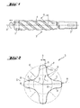
- Die Erfindung wird bezüglich eines vorteilhaften Ausführungsbeispiels näher erläutert mit:
- Fig. 1 als Drehschlagbohrer
- Fig. 2 als Wendelquerschnitt
- Nach Fig. 1 weist ein Drehschlagbohrer für Gestein einen axial zwischen einem hartstoffbestückten Bohrkopf 1, in Form eines stumpf angelöteten Vollhartstoffkopfes, und einem Einsteckende 2 angeordneten viergängigen Bohrwendelschaft 3 mit vier Wendelstegen 4 auf, die jeweils eine zur Bohrachse A bestimmte Wendelsteigung [alpha] der Wendelstege 4 von 48° aufweisen.
- Nach Fig. 2 ist der Wendelquerschnitt vierzählig rotations- und spiegelsymmetrisch, wobei die von einem Nutengrund 5 bis zu einem Hüllkreis 6 mit dem Hüllkreisradius H radial auskragenden Wendelstege 4 konvex ausgebildet sind und bezüglich ihrer Stegbreite S einen Hinterschnitt 7 ausbilden. Ein in den Wendelquerschnitt einschreibbarer Innenkreis 8 weist einen Innenkreisradius I von der Hälfte des Hüllkreisradius H auf. Der Hinterschnitt 7 ist an einen Hinterschnittradius R bei drei Viertel des Hüllkreisradius H angeordnet. Der konkav geformte Nutengrund 5 weist einen Nutengrundradius N von der Hälfte des Hüllkreisradius H auf. Eine radial äussere Randbreite B des Wendelstegs 4 liegt bei einem Siebentel des Hüllkreisradius H, wobei der Wendelsteg 4 in einen Hüllkreisbogen 9 übergeht. Zwischen dem konkav ausgeformten Nutengrund 5 und dem Hüllkreisbogen 9 ist ein konvex ausgeformter Flankenrand 10 ausgebildet, der glatt in den Nutengrund 5 übergeht. Der Flankenrand 10 weist einen Flankenrandradius F von einem Drittel des Hüllkreisradius H auf.
Claims (10)
- Drehschlagbohrer für Gestein mit einem viergängigen Bohrwendelschaft (3) mit einem vierzählig rotations- und spiegelsymmetrischen Wendelquerschnitt, in welchen die vom Nutengrund (5) bis zu einem Hüllkreisradius (H) radial auskragenden Wendelstege (4) konvex ausgebildet sind und bezüglich ihrer Stegbreite (S) einen Hinterschnitt (7) ausbilden, dadurch gekennzeichnet, dass der Nutengrund (5) konkav ausgebildet ist.
- Drehschlagbohrer nach Anspruch 1, dadurch gekennzeichnet, dass ein in den Wendelquerschnitt einschreibbarer Innenkreis (8) einen Innenkreisradius (I) von einem Drittel bis zwei Dritteln des Hüllkreisradius (H) aufweist.
- Drehschlagbohrer nach Anspruch 1 oder 2, dadurch gekennzeichnet, dass der Hinterschnitt an einen Hinterschnittradius (R) im Bereich von der Hälfte bis zwei Dritteln des Hüllkreisradius (H) angeordnet ist.
- Drehschlagbohrer nach einem der Ansprüche 1 bis 3, dadurch gekennzeichnet, dass im Wendelquerschnitt der Nutengrund (5) einen Nutengrundradius (N) im Bereich von einem Drittel bis zwei Dritteln des Hüllkreisradius (H) aufweist.
- Drehschlagbohrer nach einem der Ansprüche 1 bis 4, dadurch gekennzeichnet, dass im Wendelquerschnitt eine radial äussere Randbreite (B) des Wendelstegs (4) im Bereich von einem Achtel bis zu einem Sechstel des Hüllkreisradius (H) liegt.
- Drehschlagbohrer nach einem der Ansprüche 1 bis 5, dadurch gekennzeichnet, dass im Wendelquerschnitt der Wendelsteg (4) radial aussen in einen Hüllkreisbogen (9) übergeht.
- Drehschlagbohrer nach Anspruch 6, dadurch gekennzeichnet, dass im Wendelquerschnitt zwischen dem konkav ausgeformten Nutengrund (5) und dem Hüllkreisbogen (9) ein konvex ausgeformter Flankenrand (10) ausgebildet ist.
- Drehschlagbohrer nach Anspruch 7, dadurch gekennzeichnet, dass im Wendelquerschnitt der Nutengrund (5) glatt in den Flankenrand (10) übergeht.
- Drehschlagbohrer nach Anspruch 6 oder 7, dadurch gekennzeichnet, dass im Wendelquerschnitt der Flankenrand (10) einen Flankenrandradius (F) im Bereich von einem Viertel bis der Hälfte des Hüllkreisradius (H) aufweist.
- Drehschlagbohrer einem der Ansprüche 1 bis 9, dadurch gekennzeichnet, dass eine zur Bohrachse (A) bestimmte Wendelsteigung ([alpha]) des Wendelsteges (4) im Bereich von 45° bis 55° liegt.
Applications Claiming Priority (1)
| Application Number | Priority Date | Filing Date | Title |
|---|---|---|---|
| DE102006000208A DE102006000208A1 (de) | 2006-04-28 | 2006-04-28 | Drehschlagbohrer mit viergängigem Bohrwendelschaft |
Publications (2)
| Publication Number | Publication Date |
|---|---|
| EP1849955A1 true EP1849955A1 (de) | 2007-10-31 |
| EP1849955B1 EP1849955B1 (de) | 2009-06-17 |
Family
ID=38266698
Family Applications (1)
| Application Number | Title | Priority Date | Filing Date |
|---|---|---|---|
| EP07106506A Active EP1849955B1 (de) | 2006-04-28 | 2007-04-19 | Drehschlagbohrer mit viergängigem Bohrwendelschaft |
Country Status (6)
| Country | Link |
|---|---|
| US (1) | US7628232B2 (de) |
| EP (1) | EP1849955B1 (de) |
| JP (1) | JP5156262B2 (de) |
| AT (1) | ATE434114T1 (de) |
| AU (1) | AU2007201794B2 (de) |
| DE (2) | DE102006000208A1 (de) |
Cited By (2)
| Publication number | Priority date | Publication date | Assignee | Title |
|---|---|---|---|---|
| EP2067555A1 (de) * | 2007-12-05 | 2009-06-10 | Techtronic Industries Company Limited | Bohrmeißel |
| EP3222390A1 (de) * | 2016-03-23 | 2017-09-27 | HILTI Aktiengesellschaft | Meissel |
Families Citing this family (14)
| Publication number | Priority date | Publication date | Assignee | Title |
|---|---|---|---|---|
| US7740088B1 (en) * | 2007-10-30 | 2010-06-22 | The United States Of America As Represented By The Administrator Of The National Aeronautics And Space Administration | Ultrasonic rotary-hammer drill |
| AU325828S (en) * | 2008-09-23 | 2009-04-23 | Illinois Tool Works | Drill bit |
| US7861807B2 (en) * | 2008-12-03 | 2011-01-04 | Black & Decker Inc. | Drill bit including one piece cutting head |
| DE102009003288A1 (de) * | 2009-05-20 | 2010-11-25 | Hilti Aktiengesellschaft | Bohrer |
| DE102009003287A1 (de) * | 2009-05-20 | 2010-11-25 | Hilti Aktiengesellschaft | Bohrer |
| DE102010002167A1 (de) * | 2010-02-22 | 2011-08-25 | Hilti Aktiengesellschaft | Herstellungsverfahren für ein Einsteckende |
| BR112013012595A2 (pt) * | 2010-11-26 | 2017-07-11 | Cpl Holdings Pty Ltd | broca de perfuração |
| DE102012202300A1 (de) * | 2012-02-15 | 2013-08-22 | Hilti Aktiengesellschaft | Meißel |
| EP2669033B1 (de) | 2012-05-29 | 2015-11-04 | Black & Decker Inc. | Schneidkopf für einen Bohrer. |
| EP3012039A1 (de) * | 2014-10-23 | 2016-04-27 | HILTI Aktiengesellschaft | Wendelbohrer und Herstellungsverfahren |
| EP3059007A1 (de) | 2015-02-23 | 2016-08-24 | Umicore AG & Co. KG | Rührer zum rühren von geschmolzenem glas, vorrichtung zum rühren von geschmolzenem glas mit solch einem rührer und verwendung solch eines rührers |
| EP3106253A1 (de) | 2015-06-17 | 2016-12-21 | HILTI Aktiengesellschaft | Bohrer und herstellungsverfahren |
| USD857772S1 (en) * | 2017-10-26 | 2019-08-27 | B+Btec International Bv | Drilling tool |
| USD1034137S1 (en) | 2022-10-07 | 2024-07-09 | Milwaukee Electric Tool Corporation | Drill bit |
Citations (4)
| Publication number | Priority date | Publication date | Assignee | Title |
|---|---|---|---|---|
| US2895355A (en) * | 1953-03-04 | 1959-07-21 | Maskin R L Carlstedt Fa | Drill shank for drills |
| US4749051A (en) * | 1984-10-01 | 1988-06-07 | Santrade Limited | Drill steel |
| DE9319009U1 (de) * | 1993-12-10 | 1994-02-03 | Plica Werkzeugfabrik Ag, Mollis | Dreischneidenbohrer |
| DE19915304A1 (de) * | 1999-03-22 | 2000-09-28 | Hawera Probst Gmbh | Bohrwerkzeug |
Family Cites Families (6)
| Publication number | Priority date | Publication date | Assignee | Title |
|---|---|---|---|---|
| DE206517C (de) | ||||
| US2673716A (en) | 1950-09-02 | 1954-03-30 | Clyde E Avery | Bit |
| DE4419641A1 (de) | 1994-06-04 | 1995-12-07 | Hilti Ag | Gesteinsbohrer |
| US7097396B1 (en) * | 2000-02-16 | 2006-08-29 | Kabushiki Kaisha Miyanaga | Drill bit |
| JP2002317595A (ja) * | 2001-04-18 | 2002-10-31 | Asahi Tec Corp | 掘削用ドリル |
| US6601659B2 (en) * | 2001-05-17 | 2003-08-05 | Hilti Aktiengesellschaft | Twist drill |
-
2006
- 2006-04-28 DE DE102006000208A patent/DE102006000208A1/de not_active Withdrawn
-
2007
- 2007-04-19 DE DE502007000873T patent/DE502007000873D1/de active Active
- 2007-04-19 EP EP07106506A patent/EP1849955B1/de active Active
- 2007-04-19 AT AT07106506T patent/ATE434114T1/de active
- 2007-04-23 AU AU2007201794A patent/AU2007201794B2/en active Active
- 2007-04-27 US US11/796,737 patent/US7628232B2/en active Active
- 2007-05-01 JP JP2007121033A patent/JP5156262B2/ja active Active
Patent Citations (4)
| Publication number | Priority date | Publication date | Assignee | Title |
|---|---|---|---|---|
| US2895355A (en) * | 1953-03-04 | 1959-07-21 | Maskin R L Carlstedt Fa | Drill shank for drills |
| US4749051A (en) * | 1984-10-01 | 1988-06-07 | Santrade Limited | Drill steel |
| DE9319009U1 (de) * | 1993-12-10 | 1994-02-03 | Plica Werkzeugfabrik Ag, Mollis | Dreischneidenbohrer |
| DE19915304A1 (de) * | 1999-03-22 | 2000-09-28 | Hawera Probst Gmbh | Bohrwerkzeug |
Cited By (4)
| Publication number | Priority date | Publication date | Assignee | Title |
|---|---|---|---|---|
| EP2067555A1 (de) * | 2007-12-05 | 2009-06-10 | Techtronic Industries Company Limited | Bohrmeißel |
| EP3222390A1 (de) * | 2016-03-23 | 2017-09-27 | HILTI Aktiengesellschaft | Meissel |
| WO2017162623A1 (de) * | 2016-03-23 | 2017-09-28 | Hilti Aktiengesellschaft | Meissel |
| US11213939B2 (en) | 2016-03-23 | 2022-01-04 | Hilti Aktiengesellschaft | Chisel |
Also Published As
| Publication number | Publication date |
|---|---|
| AU2007201794A1 (en) | 2007-11-15 |
| US7628232B2 (en) | 2009-12-08 |
| US20070251734A1 (en) | 2007-11-01 |
| AU2007201794B2 (en) | 2010-04-29 |
| JP2007296851A (ja) | 2007-11-15 |
| ATE434114T1 (de) | 2009-07-15 |
| DE502007000873D1 (de) | 2009-07-30 |
| JP5156262B2 (ja) | 2013-03-06 |
| EP1849955B1 (de) | 2009-06-17 |
| DE102006000208A1 (de) | 2007-10-31 |
Similar Documents
| Publication | Publication Date | Title |
|---|---|---|
| EP1849955B1 (de) | Drehschlagbohrer mit viergängigem Bohrwendelschaft | |
| DE3853518T3 (de) | Spiralbohrer. | |
| EP1125664B1 (de) | Bohrwerkzeug für Gestein | |
| EP0118035A1 (de) | Bohrwerkzeug mit Verfahren zur Herstellung eines Bohrwerkzeugs | |
| EP1259699B1 (de) | Gesteinsbohrer | |
| DE102014111846A1 (de) | Spiralbohrer mit Keramikeinsätzen | |
| DE10244509A1 (de) | Spitzmeissel | |
| DE3407427A1 (de) | Bohrkrone | |
| DE102011086422B4 (de) | Verfahren zur Herstellung eines Werkzeuges, sowie ein solches Werkzeug | |
| AT4227U1 (de) | Bohrer | |
| EP2771143B1 (de) | Bohrer und herstellungsverfahren für einen bohrer | |
| DE10053342A1 (de) | Wendelbohrer | |
| EP0937860A1 (de) | Bohr- und/oder Meisselwerkzeug | |
| EP1083294B1 (de) | Bohrwerkzeug | |
| DE20219753U1 (de) | Tieflochbohrer | |
| EP1015727B1 (de) | Bohrwerkzeug | |
| DE1927754C3 (de) | Gesteinsbohrer | |
| DE102007055774A1 (de) | Kernbohrkrone für Gestein | |
| EP1319455A1 (de) | Gesteinskernbohrkrone | |
| DE106808C (de) | ||
| DE102013205363A1 (de) | Werkzeugkopf sowie Verfahren zur Bearbeitung eines metallischen Werkstücks | |
| DE2423510A1 (de) | Gesteinsbohrer | |
| DE20212852U1 (de) | Mehrstufen-Bohrwerkzeug | |
| DE8303470U1 (de) | Wendelbohrwerkzeug | |
| DE202017103022U1 (de) | Schaftfräser |
Legal Events
| Date | Code | Title | Description |
|---|---|---|---|
| PUAI | Public reference made under article 153(3) epc to a published international application that has entered the european phase |
Free format text: ORIGINAL CODE: 0009012 |
|
| AK | Designated contracting states |
Kind code of ref document: A1 Designated state(s): AT BE BG CH CY CZ DE DK EE ES FI FR GB GR HU IE IS IT LI LT LU LV MC MT NL PL PT RO SE SI SK TR |
|
| AX | Request for extension of the european patent |
Extension state: AL BA HR MK YU |
|
| 17P | Request for examination filed |
Effective date: 20080502 |
|
| AKX | Designation fees paid |
Designated state(s): AT CH DE FR GB IT LI |
|
| GRAP | Despatch of communication of intention to grant a patent |
Free format text: ORIGINAL CODE: EPIDOSNIGR1 |
|
| GRAS | Grant fee paid |
Free format text: ORIGINAL CODE: EPIDOSNIGR3 |
|
| GRAA | (expected) grant |
Free format text: ORIGINAL CODE: 0009210 |
|
| AK | Designated contracting states |
Kind code of ref document: B1 Designated state(s): AT CH DE FR GB IT LI |
|
| REG | Reference to a national code |
Ref country code: GB Ref legal event code: FG4D Free format text: NOT ENGLISH |
|
| REG | Reference to a national code |
Ref country code: CH Ref legal event code: EP |
|
| REF | Corresponds to: |
Ref document number: 502007000873 Country of ref document: DE Date of ref document: 20090730 Kind code of ref document: P |
|
| PLBE | No opposition filed within time limit |
Free format text: ORIGINAL CODE: 0009261 |
|
| STAA | Information on the status of an ep patent application or granted ep patent |
Free format text: STATUS: NO OPPOSITION FILED WITHIN TIME LIMIT |
|
| 26N | No opposition filed |
Effective date: 20100318 |
|
| REG | Reference to a national code |
Ref country code: CH Ref legal event code: PL |
|
| PGFP | Annual fee paid to national office [announced via postgrant information from national office to epo] |
Ref country code: IT Payment date: 20100430 Year of fee payment: 4 |
|
| PG25 | Lapsed in a contracting state [announced via postgrant information from national office to epo] |
Ref country code: LI Free format text: LAPSE BECAUSE OF NON-PAYMENT OF DUE FEES Effective date: 20110430 Ref country code: CH Free format text: LAPSE BECAUSE OF NON-PAYMENT OF DUE FEES Effective date: 20110430 |
|
| REG | Reference to a national code |
Ref country code: FR Ref legal event code: PLFP Year of fee payment: 10 |
|
| REG | Reference to a national code |
Ref country code: FR Ref legal event code: PLFP Year of fee payment: 11 |
|
| REG | Reference to a national code |
Ref country code: FR Ref legal event code: PLFP Year of fee payment: 12 |
|
| PGFP | Annual fee paid to national office [announced via postgrant information from national office to epo] |
Ref country code: DE Payment date: 20250422 Year of fee payment: 19 |
|
| PGFP | Annual fee paid to national office [announced via postgrant information from national office to epo] |
Ref country code: GB Payment date: 20250418 Year of fee payment: 19 |
|
| PGFP | Annual fee paid to national office [announced via postgrant information from national office to epo] |
Ref country code: FR Payment date: 20250423 Year of fee payment: 19 |
|
| PGFP | Annual fee paid to national office [announced via postgrant information from national office to epo] |
Ref country code: AT Payment date: 20250423 Year of fee payment: 19 |