EP1848954B1 - Kinetic energy rod warhead with aiming mechanism - Google Patents
Kinetic energy rod warhead with aiming mechanism Download PDFInfo
- Publication number
- EP1848954B1 EP1848954B1 EP05857584A EP05857584A EP1848954B1 EP 1848954 B1 EP1848954 B1 EP 1848954B1 EP 05857584 A EP05857584 A EP 05857584A EP 05857584 A EP05857584 A EP 05857584A EP 1848954 B1 EP1848954 B1 EP 1848954B1
- Authority
- EP
- European Patent Office
- Prior art keywords
- explosive
- segment
- explosive segment
- segments
- kinetic energy
- Prior art date
- Legal status (The legal status is an assumption and is not a legal conclusion. Google has not performed a legal analysis and makes no representation as to the accuracy of the status listed.)
- Active
Links
- 239000002360 explosive Substances 0.000 claims description 214
- 230000002889 sympathetic effect Effects 0.000 claims description 39
- 239000013598 vector Substances 0.000 claims description 28
- 238000000034 method Methods 0.000 claims description 23
- 230000035939 shock Effects 0.000 claims description 9
- 239000002131 composite material Substances 0.000 claims description 7
- 229910000831 Steel Inorganic materials 0.000 claims description 5
- 229920005668 polycarbonate resin Polymers 0.000 claims description 5
- 239000004431 polycarbonate resin Substances 0.000 claims description 5
- 239000010959 steel Substances 0.000 claims description 5
- WFKWXMTUELFFGS-UHFFFAOYSA-N tungsten Chemical compound [W] WFKWXMTUELFFGS-UHFFFAOYSA-N 0.000 claims description 5
- 229910052721 tungsten Inorganic materials 0.000 claims description 5
- 239000010937 tungsten Substances 0.000 claims description 5
- 238000005474 detonation Methods 0.000 description 16
- 238000013467 fragmentation Methods 0.000 description 5
- 238000006062 fragmentation reaction Methods 0.000 description 5
- 238000010304 firing Methods 0.000 description 3
- 231100000225 lethality Toxicity 0.000 description 3
- 239000007921 spray Substances 0.000 description 3
- 239000000126 substance Substances 0.000 description 3
- 230000001419 dependent effect Effects 0.000 description 2
- 238000005516 engineering process Methods 0.000 description 2
- 239000000463 material Substances 0.000 description 2
- 229910052751 metal Inorganic materials 0.000 description 2
- 239000002184 metal Substances 0.000 description 2
- 229910052782 aluminium Inorganic materials 0.000 description 1
- XAGFODPZIPBFFR-UHFFFAOYSA-N aluminium Chemical compound [Al] XAGFODPZIPBFFR-UHFFFAOYSA-N 0.000 description 1
- 230000003247 decreasing effect Effects 0.000 description 1
- 239000012634 fragment Substances 0.000 description 1
- 230000035515 penetration Effects 0.000 description 1
- 230000032258 transport Effects 0.000 description 1
Images


Classifications
-
- F—MECHANICAL ENGINEERING; LIGHTING; HEATING; WEAPONS; BLASTING
- F42—AMMUNITION; BLASTING
- F42B—EXPLOSIVE CHARGES, e.g. FOR BLASTING, FIREWORKS, AMMUNITION
- F42B12/00—Projectiles, missiles or mines characterised by the warhead, the intended effect, or the material
- F42B12/02—Projectiles, missiles or mines characterised by the warhead, the intended effect, or the material characterised by the warhead or the intended effect
- F42B12/36—Projectiles, missiles or mines characterised by the warhead, the intended effect, or the material characterised by the warhead or the intended effect for dispensing materials; for producing chemical or physical reaction; for signalling ; for transmitting information
- F42B12/56—Projectiles, missiles or mines characterised by the warhead, the intended effect, or the material characterised by the warhead or the intended effect for dispensing materials; for producing chemical or physical reaction; for signalling ; for transmitting information for dispensing discrete solid bodies
- F42B12/58—Cluster or cargo ammunition, i.e. projectiles containing one or more submissiles
- F42B12/60—Cluster or cargo ammunition, i.e. projectiles containing one or more submissiles the submissiles being ejected radially
-
- F—MECHANICAL ENGINEERING; LIGHTING; HEATING; WEAPONS; BLASTING
- F42—AMMUNITION; BLASTING
- F42B—EXPLOSIVE CHARGES, e.g. FOR BLASTING, FIREWORKS, AMMUNITION
- F42B12/00—Projectiles, missiles or mines characterised by the warhead, the intended effect, or the material
- F42B12/02—Projectiles, missiles or mines characterised by the warhead, the intended effect, or the material characterised by the warhead or the intended effect
- F42B12/04—Projectiles, missiles or mines characterised by the warhead, the intended effect, or the material characterised by the warhead or the intended effect of armour-piercing type
- F42B12/06—Projectiles, missiles or mines characterised by the warhead, the intended effect, or the material characterised by the warhead or the intended effect of armour-piercing type with hard or heavy core; Kinetic energy penetrators
-
- F—MECHANICAL ENGINEERING; LIGHTING; HEATING; WEAPONS; BLASTING
- F42—AMMUNITION; BLASTING
- F42C—AMMUNITION FUZES; ARMING OR SAFETY MEANS THEREFOR
- F42C19/00—Details of fuzes
- F42C19/08—Primers; Detonators
- F42C19/095—Arrangements of a multiplicity of primers or detonators, dispersed around a warhead, one of the primers or detonators being selected for directional detonation effects
Definitions
- This subject invention relates to improvements in kinetic energy rod warheads.
- Destroying missiles, aircraft, re-entry vehicles and other targets falls into three primary classifications: "hit-to-kill" vehicles, blast fragmentation warheads, and kinetic energy rod warheads.
- “Hit-to-kill” vehicles are typically launched into a position proximate a re-entry vehicle or other target via a missile such as the Patriot, Trident or MX missile.
- the kill vehicle is navigable and designed to strike the re-entry vehicle to render it inoperable. Countermeasures, however, can be used to avoid the "hit-to-kill” vehicle.
- biological warfare bomblets and chemical warfare submunition payloads are carried by some "hit-to-kill" threats and one or more of these bomblets or chemical submunition payloads can survive and cause heavy casualties even if the "hit-to-kill" vehicle accurately strikes the target.
- Blast fragmentation type warheads are designed to be carried by existing missiles.
- Blast fragmentation type warheads unlike "hit-to-kill" vehicles, are not navigable. Instead, when the missile carrier reaches a position close to an enemy missile or other target, a pre-made band of metal on the warhead is detonated and the pieces of metal are accelerated with high velocity and strike the target. The fragments, however, are not always effective at destroying the target and, again, biological bomblets and/or chemical submunition payloads survive and cause heavy casualties.
- the primary components associated with a theoretical kinetic energy rod warhead are a projectile core or bay including a number of individual lengthy rod projectiles or penetrators, and an explosive charge. When the explosive charge is detonated, the rod projectiles or penetrators are deployed. Typically, these components are within a hull or housing.
- the explosive charge can be divided into a number of explosive charge segments or sections, with sympathetic shields between these segments. Each explosive segment may have its own detonator. Selected explosive charge segments are detonated to aim the projectiles in a specific direction and to control the spread pattern of the projectiles. For instance, detonators on one side of the projectile core can be detonated to cause their associated explosive charge segments to eject specified hull sections, creating an opening in the hull on the target side. Other detonators on the opposite side of the core are detonated to deploy the projectile rods in the direction of the opening and thus towards the target. See e.g. German patent document DE 195 24 726 which forms a starting point for the current invention, and U.S. Pat. No. 6,598,534 and U.S. Pat. Publ. No. 20040055500A1 .
- the exact position of the target in relation to the warhead explosive charge segments may affect aiming accuracy.
- the target may be positioned relative to the warhead such that the center of the rod set does not travel close to the target direction, resulting in aiming errors.
- the target may be in a position where deploying one set of explosive segments, i.e. three adjacent segments, will result in the center of the rod core travelling in a direction which is not the target direction, but where deploying a different set of explosive segments, i.e. four adjacent segments, still may not direct the rods towards the target as desired.
- the number of explosive segments detonated will affect the total spray pattern diameter, which may be critical in some applications.
- the subject invention results from the realization that a kinetic energy rod warhead with enhanced aiming resolution can be achieved with explosive charge segments deployed in timed combinations to drive the rods in a specific deployment direction to more accurately strike a target.
- the present invention thus provides a unique way to destroy a target.
- This invention features an aimable kinetic energy rod warhead system including a plurality of rods, explosive segments disposed about the plurality of rods, and at least one detonator for each explosive segment.
- a target locator system is configured to locate a target relative to the explosive segments and a controller is responsive to the target locator system.
- the controller is configured to selectively detonate specified explosive segments at different times dependent on the desired deployment direction of the rods to improve aiming resolution of the warhead.
- the selective detonation of specified explosive segments generates deployment vectors. The sum of the deployment vectors is a resolved deployment vector in the desired deployment direction.
- the warhead system may include eight explosive segments and there may be one detonator for each explosive segment.
- the warhead system may include sympathetic shields between each explosive segment, and the shields may be made of a composite material, which may be steel sandwiched between polycarbonate resin sheet layers.
- the rods may be lengthy metallic members and may be made of tungsten, and the rods may have a cylindrical cross-section.
- the explosive segments may be wedge-shaped and the explosive segments may surround the plurality of rods.
- the desired deployment direction may be aligned with the center of a first explosive segment.
- the controller may be configured to detonate an explosive segment opposite the first explosive segment.
- the controller may be configured to simultaneously detonate an explosive segment opposite the first explosive segment and two explosive segments adjacent the explosive segment opposite the first explosive segment.
- the desired deployment direction may be aligned with a first sympathetic shield.
- the controller may be configured to simultaneously detonate two explosive segments adjacent a sympathetic shield opposite the first sympathetic shield.
- the controller may be configured to simultaneously detonate four adjacent explosive segments including two explosive segments adjacent a sympathetic shield opposite the first sympathetic shield.
- the desired deployment direction may be aligned between a first sympathetic shield and the center of a first explosive segment.
- the controller may be configured to simultaneously detonate an explosive segment opposite the first explosive segment and an explosive segment adjacent thereto which is closest to the desired deployment direction, and thereafter simultaneously detonate an explosive segment adjacent the explosive segment opposite the first explosive segment which is farthest from the desired deployment direction, and a next adjacent explosive segment.
- the controller may be configured to detonate an explosive segment closest to the desired deployment direction which is adjacent an explosive segment opposite the first explosive segment, then detonate the explosive segment opposite the first explosive segment, then detonate the explosive segment farthest from the desired deployment direction which is adjacent the explosive segment opposite the first explosive segment, and thereafter detonate a next adjacent explosive segment.
- This invention also features a method of improving the aiming resolution of a kinetic energy rod warhead, the method including disposing explosive segments about a plurality of rods, locating a target relative to the explosive segments, and selectively detonating specified explosive segments at different times dependent on the desired deployment direction of the rods to improve aiming resolution.
- the method may further include disposing one detonator in each explosive segment.
- There may be eight explosive segments, and the method may further include disposing a sympathetic shield between the explosive segments.
- the shields may be made of a composite material which may be steel sandwiched between polycarbonate resin sheet layers.
- the rods may be lengthy metallic members and may be made of tungsten.
- the rods may have a cylindrical cross-section.
- the explosive segments may be wedge-shaped.
- the method may include detonating an explosive segment opposite a first explosive segment when the desired deployment direction is aligned with the center of the first explosive segment, and the method may include simultaneously detonating an explosive segment opposite a first explosive segment and two explosive segments adjacent the explosive segment opposite the first explosive segment, when the desired deployment direction is aligned with the center of the first explosive segment.
- the method may include simultaneously detonating two explosive segments adjacent a sympathetic shield opposite a first sympathetic shield when the desired deployment direction is aligned with the first sympathetic shield.
- the method may include simultaneously detonating four adjacent explosive segments including two explosive segments adjacent a sympathetic shield opposite a first sympathetic shield, when the desired deployment direction is aligned with the first sympathetic shield.
- the method may include detonating an explosive segment closest to the desired deployment direction which is adjacent an explosive segment opposite a first explosive segment, then detonating the explosive segment opposite the first explosive segment, then detonating the explosive segment farthest from desired deployment direction which is adjacent the explosive segment opposite the first explosive segment, and thereafter detonating a next adjacent explosive segment, when the desired deployment direction is aligned between a first sympathetic shield and the center of the first explosive segment.
- the method may include simultaneously detonating an explosive segment opposite a first explosive segment and an explosive segment adjacent thereto which is closest to the desired deployment direction, and thereafter simultaneously detonating an explosive segment adjacent the explosive segment opposite the first explosive segment which is farthest from the desired deployment direction and a next adjacent explosive segment, when the desired deployment direction is aligned between a first sympathetic shield and the center of the first explosive segment.
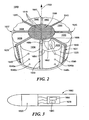
- the aimable kinetic energy rod warhead system and method of the present invention includes kinetic energy rod warhead 1500, Fig. 1 , including plurality of rods or projectiles 1510, explosive 1520 for deploying rods 1510, and at least one detonator 1540 for detonating explosive 1520. Detonation of explosive 1520 deploys projectiles 1500.
- the shape and configuration of kinetic energy rod warhead 1500 is not limited to any particular configuration.
- kinetic rod warhead 1500 typically includes projectile core 1580, thin plates 1600, 1610 and thin aluminum absorbing layers 1612, 1614 about projectiles 1510.
- explosive charge 1520 is divided into segments 1630, 1632, 1634 and 1636 disposed about plurality of rods or projectiles 1510.
- sympathetic shields 1631, 1633, 1635 separate explosive segments 1630, 1632, 1634 and 1636, and projectile rods 1510 are lengthy metallic cylindrical members.
- the rods are made of tungsten
- the sympathetic shields are made of composite material such as steel sandwiched between polycarbonate resin sheet layers, although the rods and sympathetic shields are not necessarily limited to these shapes or materials, and may be of various shapes or materials depending on a desired application.
- detonator 1540 for each explosive segment (shown for segments 1632 and 1634) and there may be multiple detonators 1540a, 1540b which may be placed as shown or at 1540', 1540a', and 1540b', Fig. 1 . Additional explosive segments 1638, 1640, 1642 and 1644, Fig. 2 are also disposed about projectile rods 1510 with their associated detonators (not shown) and are separated by sympathetic shields 1637, 1639, 1641, 1643 and 1645.
- each explosive segment is wedge-shaped with proximal surface 1650 of explosive segment 1632 abutting projectile core 1580 and distal surface 1652 which is tapered as shown at 1654 and 1656 to reduce weight.
- the explosive segments may each include a wave shaper 1658 as shown in explosive segment 1632.
- Fig. 3 transports the kinetic energy rod warhead 1500 to the vicinity of a target.
- Target locator system 1680 is configured to locate a target relative to explosive segments 1630, 1632, 1634, 1636, 1638, 1640, 1642, 1644, Fig. 2 .
- Target locator systems are known in the art, and typically are part of a guidance subsystem such as guidance subsystem 1670, Fig. 3 which includes, for example, fusing technology and is also within carrier or missile 1660, also as known in the art.
- controller 1690 is responsive to target locator system 1680 and is configured to selectively detonate specified explosive segments 1630, 1632, 1634, 1636, 1638, 1640, 1642, 1644, Fig. 2 at different times depending on the desired deployment direction of plurality of rods 1510 to improve the aiming resolution of kinetic energy rod warhead 1500.
- there are eight explosive segments in kinetic energy rod warhead 1500 but although this is a preferred embodiment, the invention is not limited to eight explosive segments.
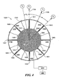
- thin frangible hull 1800, Fig. 4 typically surrounds explosive segments 1630-1642.
- any target location such as target locations T 1 , T 2 , T 3 , and T Y , Fig. 4 could be relative to a particular explosive segment.
- target locations T 1 -T 3 are in positions relative to explosive segment 1642.
- the desired deployment direction of rods 1510 is the direction of the target, such as along vector 1700 for target T 1 .
- target locator system 1680, Fig. 3 is configured to locate a target such as T 1 , T 2 , T 3 , T Y or other target
- controller 1690 is configured to selectively detonate selected or specified explosive segments at different times depending on the desired deployment direction.
- the physical constraints of the warhead hardware configuration cause no aiming difficulty.
- the warhead hardware configuration introduces aiming errors, but these errors are decreased significantly by the present invention.
- target locator system 1680 locates target at position T 1 , Fig. 4 which is aligned with sympathetic shield 1641.
- the desired deployment direction 1700 of rods 1510 is aligned with sympathetic shield 1641.
- the first way is to simultaneously detonate explosive segments 1632 and 1634, which are adjacent sympathetic shield 1633 opposite sympathetic shield 1641.
- the primary firing direction of penetrators 1510 would be in the desired deployment direction 1700 toward target T 1 , and thus rod projectiles 1510 would be deployed from kinetic energy rod warhead 1500 in the direction as shown.
- a second way to deploy rod projectiles 1510 towards T 1 is to simultaneously deploy four adjacent explosive segments 1630, 1632, 1634 and 1636, which inc ludes explosive segments 1632 and 1634 adjacent sympathetic shield 1633.
- the desired deployment vector 1720 is aligned with the center 1710 of explosive segment 1642.
- a first way is to detonate explosive segment 1634 which is opposite explosive segment 1642.
- a second way is to simultaneously detonate explosive segments 1634, and explosive segments 1632 and 1636 which are adjacent segment 1634. Detonating the explosive segments in either manner will result in little if any aiming errors, again despite the physical constraints of the kinetic energy rod warhead.
- the warhead hardware restricts the most accurate firing options to a) detonating one explosive segment, i.e. explosive segment 1632, or b) detonating three explosive segments, i.e. explosive segments 1630, 1632, and 1634 simultaneously. Either of these firing options could result in an aiming error of ⁇ E , namely 11.125°. With such an error, for a spray angle of 35° at a miss distance of 5 feet, there would not be complete overlap of the plurality of rods 1510 with target T Y after detonation, as shown in Fig. 5 .
- controller 1690 is configured to selectively detonate specified explosive segments to decrease aiming errors significantly and improve aiming resolution.
- controller 1690 is configured to first simultaneously detonate explosive segment 1632 which is opposite explosive segment 1640, and explosive segment 1630 which is adjacent explosive segment 1632 and closest to desired deployment direction 1730.
- Controller 1690 is further configured to thereafter simultaneously detonate explosive segment 1634 which is adjacent explosive segment 1632 and farthest from desired deployment direction 1730, and next adjacent explosive segment 1636.
- the time delay between the simultaneous detonation of segments 1630 and 1632 and the subsequent simultaneous detonation of segments 1634 and 1636 may be between 8.0 microseconds and 9.0 microseconds, preferably about 8.33 microseconds.
- the rods can be aimed in any desired deployment direction.
- This high resolution aiming is caused by differential shock waves in the explosive segments and how their vectors combine.
- explosive segments 1630 and 1632 are detonated first, causing shock wave 1770 and generating a deployment vector V 12 which signifies the simultaneous detonation of the first two explosive segments 1630 and 1632.
- explosive segments 1634 and 1636 are detonated.
- the simultaneous detonation of explosive segments 1634 and 1636 causes another shock wave 1771 and generates deployment vector V 34 .
- the sum of deployment vectors V 12 and V 34 is resolved vector V d which is the direction in which plurality of rods 1510 travel. More particularly, center 1775 of plurality of rods 1510 travels in direction V d , which is the same direction as desired deployment direction 1730. Thus aiming resolution is greatly improved.
- the angle ⁇ Y is the difference between the direction of resolved vector V d and the direction of travel 1700 of plurality of rods 1510 if, for example, explosive segments 1630, 1632, 1634 and 1636 were all detonated simultaneously rather than at different times.
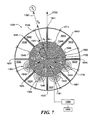
- target T Z located by target locator system 1680 is also aligned between sympathetic shield 1641 and center 1710 of explosive segment 1642.
- target T z is aligned further away from sympathetic shield 1641 than target T Y , Fig. 6 and the angle ⁇ Z is greater than angle ⁇ Y , Fig. 7 .
- the invention utilizes time difference to bias the deployment vectors and improve aiming resolution.
- controller 1680 is configured to sequentially detonate explosive segments 1630, 1632, 1634 and 1636. Controller 1680 is configured to first detonate explosive segment 1630 closest to desired deployment direction 1780 and adjacent explosive segment 1632 which is opposite explosive segment 1640. Then explosive segment 1632 opposite segment 1640 is detonated. Explosive segment 1634 farthest from desired deployment direction 1780 and adjacent explosive segment 1632 is then detonated. The next adjacent explosive segment 1636 is detonated last. The time period between the detonations may be adjusted according to the exact location of a specific target. In one example, the time between the sequential detonation of each explosive segment 1630, 1632, 1634 and 1636 is approximately four (4) microseconds.
- explosive segment 1630 is detonated first, causing shock wave 1779 and generating deployment vector V 1 . Then explosive segment 1632 is detonated, causing shock wave 1781 and generating deployment vector V 2 . Thereafter explosive segment 1634 is detonated, causing shock wave 1783 and generating deployment vector V 3 . Explosive segment 1636 is detonated last, causing shock wave 1785 and generating deployment vector V 4 .
- the sum of deployment vectors V 1 , V 2 , V 3 and V 4 is resolved vector V R which is the direction plurality of rods 1510 -- specifically the center 1775 of plurality of rods 1510 -- travel. The direction of resolved vector V R is the same as desired deployment direction 1780. Again there is a great reduction in aiming error.
- the angle ⁇ Z is the difference between the direction of resolved vector V R and the direction of travel 1700 of plurality of rods 1510 if, for example, explosive segments 1630, 1632, 1634 and 1636 were detonated simultaneously rather than each at different times. Also, the difference between ⁇ Y , Fig. 5 and ⁇ Z , Fig. 6 is the difference between a) simultaneous detonation of segments 1630 and 1632 first followed by simultaneous detonation of segments 1634 and 1636, and b) the sequential detonation of segments 1630, 1632, 1634 and 1636.
- a target located between any sympathetic shield center and any of an explosive segment may be more accurately targeted.
- the target is at T A , Fig. 7 , between sympathetic shield 1641, Fig. 7 , and center 1711 of explosive segment 1642
- explosive segments 1634 and 1636 may be simultaneously detonated, followed by the simultaneous detonation of segments 1632 and 1630.
- explosive segments 1636 may be detonated first, followed by the detonation of explosive segment 1634, then 1632, then 1630 in order.
- the amount of time between detonation of any of the explosive segments is not limited, and may be adjusted according to the location of a particular target and desired deployment direction.
- the directions of the deployment vectors, and consequently the resolved deployment vector can be adjusted to any desired deployment direction and/or any target location.
- aiming resolution is improved and rod penetrators of the aimable kinetic energy rod warhead of the present invention are more accurately propelled in the direction of a target to increase overall kill probability and lethality.
Description
- This subject invention relates to improvements in kinetic energy rod warheads.
- Destroying missiles, aircraft, re-entry vehicles and other targets falls into three primary classifications: "hit-to-kill" vehicles, blast fragmentation warheads, and kinetic energy rod warheads.
- "Hit-to-kill" vehicles are typically launched into a position proximate a re-entry vehicle or other target via a missile such as the Patriot, Trident or MX missile. The kill vehicle is navigable and designed to strike the re-entry vehicle to render it inoperable. Countermeasures, however, can be used to avoid the "hit-to-kill" vehicle. Moreover, biological warfare bomblets and chemical warfare submunition payloads are carried by some "hit-to-kill" threats and one or more of these bomblets or chemical submunition payloads can survive and cause heavy casualties even if the "hit-to-kill" vehicle accurately strikes the target.
- Blast fragmentation type warheads are designed to be carried by existing missiles. Blast fragmentation type warheads, unlike "hit-to-kill" vehicles, are not navigable. Instead, when the missile carrier reaches a position close to an enemy missile or other target, a pre-made band of metal on the warhead is detonated and the pieces of metal are accelerated with high velocity and strike the target. The fragments, however, are not always effective at destroying the target and, again, biological bomblets and/or chemical submunition payloads survive and cause heavy casualties.
- The textbooks by the inventor hereof, R. Lloyd, "Conventional Warhead Systems Physics and Engineering Design," Progress in Astronautics and Aeronautics (AIAA) Book Series, Vol. 179, ISBN 1-56347-255-4, 1998, and "Physics of Direct Hit and Near Miss Warhead Technology", Volume 194, ISBN 1-56347-473-5, provide additional details concerning "hit-to-kill" vehicles and blast fragmentation type warheads. Chapter 4 and Chapter 3 of these textbooks propose a kinetic energy rod warhead.
- The two primary advantages of a kinetic energy rod warhead is that 1) it does not rely on precise navigation as is the case with "hit-to-kill" vehicles and 2) it provides better penetration than blast fragmentation type warheads.
- The primary components associated with a theoretical kinetic energy rod warhead are a projectile core or bay including a number of individual lengthy rod projectiles or penetrators, and an explosive charge. When the explosive charge is detonated, the rod projectiles or penetrators are deployed. Typically, these components are within a hull or housing.
- Greater lethality is achieved when all of the rods are deployed to interrupt the target. In order to aim the projectiles in a specific direction, the explosive charge can be divided into a number of explosive charge segments or sections, with sympathetic shields between these segments. Each explosive segment may have its own detonator. Selected explosive charge segments are detonated to aim the projectiles in a specific direction and to control the spread pattern of the projectiles. For instance, detonators on one side of the projectile core can be detonated to cause their associated explosive charge segments to eject specified hull sections, creating an opening in the hull on the target side. Other detonators on the opposite side of the core are detonated to deploy the projectile rods in the direction of the opening and thus towards the target. See e.g. German patent document
DE 195 24 726 which forms a starting point for the current invention, andU.S. Pat. No. 6,598,534 andU.S. Pat. Publ. No. 20040055500A1 . - While a kinetic energy warhead including the foregoing design may be highly effective, the exact position of the target in relation to the warhead explosive charge segments may affect aiming accuracy. The target may be positioned relative to the warhead such that the center of the rod set does not travel close to the target direction, resulting in aiming errors. For example, the target may be in a position where deploying one set of explosive segments, i.e. three adjacent segments, will result in the center of the rod core travelling in a direction which is not the target direction, but where deploying a different set of explosive segments, i.e. four adjacent segments, still may not direct the rods towards the target as desired. Additionally, the number of explosive segments detonated will affect the total spray pattern diameter, which may be critical in some applications.
- It is therefore an object of this invention to provide an improved kinetic energy rod warhead.
- It is a further object of this invention to provide a higher lethality kinetic energy rod warhead.
- It is a further object of this invention to provide a kinetic energy rod warhead which has a better chance of destroying a target.
- It is a further object of this invention to provide a kinetic energy rod warhead with improved aiming accuracy.
- The subject invention results from the realization that a kinetic energy rod warhead with enhanced aiming resolution can be achieved with explosive charge segments deployed in timed combinations to drive the rods in a specific deployment direction to more accurately strike a target.
- The present invention thus provides a unique way to destroy a target.
- This invention features an aimable kinetic energy rod warhead system including a plurality of rods, explosive segments disposed about the plurality of rods, and at least one detonator for each explosive segment. A target locator system is configured to locate a target relative to the explosive segments and a controller is responsive to the target locator system. The controller is configured to selectively detonate specified explosive segments at different times dependent on the desired deployment direction of the rods to improve aiming resolution of the warhead. The selective detonation of specified explosive segments generates deployment vectors. The sum of the deployment vectors is a resolved deployment vector in the desired deployment direction. The warhead system may include eight explosive segments and there may be one detonator for each explosive segment. The warhead system may include sympathetic shields between each explosive segment, and the shields may be made of a composite material, which may be steel sandwiched between polycarbonate resin sheet layers. The rods may be lengthy metallic members and may be made of tungsten, and the rods may have a cylindrical cross-section. The explosive segments may be wedge-shaped and the explosive segments may surround the plurality of rods.
- The desired deployment direction may be aligned with the center of a first explosive segment. The controller may be configured to detonate an explosive segment opposite the first explosive segment. The controller may be configured to simultaneously detonate an explosive segment opposite the first explosive segment and two explosive segments adjacent the explosive segment opposite the first explosive segment.
- The desired deployment direction may be aligned with a first sympathetic shield. The controller may be configured to simultaneously detonate two explosive segments adjacent a sympathetic shield opposite the first sympathetic shield. The controller may be configured to simultaneously detonate four adjacent explosive segments including two explosive segments adjacent a sympathetic shield opposite the first sympathetic shield.
- The desired deployment direction may be aligned between a first sympathetic shield and the center of a first explosive segment. The controller may be configured to simultaneously detonate an explosive segment opposite the first explosive segment and an explosive segment adjacent thereto which is closest to the desired deployment direction, and thereafter simultaneously detonate an explosive segment adjacent the explosive segment opposite the first explosive segment which is farthest from the desired deployment direction, and a next adjacent explosive segment. The controller may be configured to detonate an explosive segment closest to the desired deployment direction which is adjacent an explosive segment opposite the first explosive segment, then detonate the explosive segment opposite the first explosive segment, then detonate the explosive segment farthest from the desired deployment direction which is adjacent the explosive segment opposite the first explosive segment, and thereafter detonate a next adjacent explosive segment.
- This invention also features a method of improving the aiming resolution of a kinetic energy rod warhead, the method including disposing explosive segments about a plurality of rods, locating a target relative to the explosive segments, and selectively detonating specified explosive segments at different times dependent on the desired deployment direction of the rods to improve aiming resolution. The method may further include disposing one detonator in each explosive segment. There may be eight explosive segments, and the method may further include disposing a sympathetic shield between the explosive segments. The shields may be made of a composite material which may be steel sandwiched between polycarbonate resin sheet layers. The rods may be lengthy metallic members and may be made of tungsten. The rods may have a cylindrical cross-section. The explosive segments may be wedge-shaped.
- The method may include detonating an explosive segment opposite a first explosive segment when the desired deployment direction is aligned with the center of the first explosive segment, and the method may include simultaneously detonating an explosive segment opposite a first explosive segment and two explosive segments adjacent the explosive segment opposite the first explosive segment, when the desired deployment direction is aligned with the center of the first explosive segment. The method may include simultaneously detonating two explosive segments adjacent a sympathetic shield opposite a first sympathetic shield when the desired deployment direction is aligned with the first sympathetic shield.
- The method may include simultaneously detonating four adjacent explosive segments including two explosive segments adjacent a sympathetic shield opposite a first sympathetic shield, when the desired deployment direction is aligned with the first sympathetic shield.
- The method may include detonating an explosive segment closest to the desired deployment direction which is adjacent an explosive segment opposite a first explosive segment, then detonating the explosive segment opposite the first explosive segment, then detonating the explosive segment farthest from desired deployment direction which is adjacent the explosive segment opposite the first explosive segment, and thereafter detonating a next adjacent explosive segment, when the desired deployment direction is aligned between a first sympathetic shield and the center of the first explosive segment.
- The method may include simultaneously detonating an explosive segment opposite a first explosive segment and an explosive segment adjacent thereto which is closest to the desired deployment direction, and thereafter simultaneously detonating an explosive segment adjacent the explosive segment opposite the first explosive segment which is farthest from the desired deployment direction and a next adjacent explosive segment, when the desired deployment direction is aligned between a first sympathetic shield and the center of the first explosive segment.
- Other objects, features and advantages will occur to those skilled in the art from the following description of a preferred embodiment and the accompanying drawings, in which:
-
Fig. 1 is a schematic cross-sectional view of one example of a kinetic energy rod warhead in accordance with the present invention; -
Fig. 2 is a schematic partial three-dimensional detailed view of the kinetic energy rod warhead ofFig. 1 ; -
Fig. 3 is a schematic view of a controller and target locator system in accordance with the present invention; -
Fig. 4 is a cross-sectional schematic view of an eight segment kinetic energy rod warhead in accordance with the present invention; -
Fig. 5 is a schematic view of a particular kinetic energy rod warhead spray pattern; and -
Figs. 6-7 are cross-sectional schematic views of an eight segment kinetic energy rod warhead in accordance with the present invention. - Current kinetic energy rod warhead designs allow a plurality of rods to be aimed, but the hardware can impose some constraints on the aiming accuracy. The present invention provides improved aiming resolution and better aiming accuracy despite such physical constraints.
- The aimable kinetic energy rod warhead system and method of the present invention includes kinetic
energy rod warhead 1500,Fig. 1 , including plurality of rods orprojectiles 1510, explosive 1520 for deployingrods 1510, and at least onedetonator 1540 for detonating explosive 1520. Detonation of explosive 1520 deploysprojectiles 1500. Notably, the shape and configuration of kineticenergy rod warhead 1500 is not limited to any particular configuration. - Although the exact configuration of the kinetic energy rod warhead may vary depending on a particular desired application or result to be achieved, in one embodiment
kinetic rod warhead 1500 typically includesprojectile core 1580,thin plates aluminum absorbing layers projectiles 1510. - Preferably,
explosive charge 1520,Fig. 2 , is divided intosegments projectiles 1510. In one example,sympathetic shields explosive segments projectile rods 1510 are lengthy metallic cylindrical members. In one embodiment, the rods are made of tungsten, and the sympathetic shields are made of composite material such as steel sandwiched between polycarbonate resin sheet layers, although the rods and sympathetic shields are not necessarily limited to these shapes or materials, and may be of various shapes or materials depending on a desired application. There is at least onedetonator 1540 for each explosive segment (shown forsegments 1632 and 1634) and there may bemultiple detonators Fig. 1 . Additionalexplosive segments Fig. 2 are also disposed aboutprojectile rods 1510 with their associated detonators (not shown) and are separated bysympathetic shields - In one variation, each explosive segment is wedge-shaped with
proximal surface 1650 ofexplosive segment 1632 abuttingprojectile core 1580 anddistal surface 1652 which is tapered as shown at 1654 and 1656 to reduce weight. The explosive segments may each include awave shaper 1658 as shown inexplosive segment 1632. In a manner similar to kinetic energy rod warheads generally, missile or other type ofcarrier 1660,Fig. 3 transports the kineticenergy rod warhead 1500 to the vicinity of a target. -
Target locator system 1680 is configured to locate a target relative toexplosive segments Fig. 2 . Target locator systems are known in the art, and typically are part of a guidance subsystem such asguidance subsystem 1670,Fig. 3 which includes, for example, fusing technology and is also within carrier ormissile 1660, also as known in the art. - In accordance with the present invention, however,
controller 1690 is responsive to targetlocator system 1680 and is configured to selectively detonate specifiedexplosive segments Fig. 2 at different times depending on the desired deployment direction of plurality ofrods 1510 to improve the aiming resolution of kineticenergy rod warhead 1500. In the embodiments described herein, there are eight explosive segments in kineticenergy rod warhead 1500, but although this is a preferred embodiment, the invention is not limited to eight explosive segments. Also, with each of the examples and embodiments herein, and with the present invention generally, thinfrangible hull 1800,Fig. 4 typically surrounds explosive segments 1630-1642. - For aiming purposes, any target location such as target locations T1, T2, T3, and TY,
Fig. 4 could be relative to a particular explosive segment. InFig. 4 , target locations T1-T3 are in positions relative toexplosive segment 1642. The desired deployment direction ofrods 1510 is the direction of the target, such as alongvector 1700 for target T1. For each example herein,target locator system 1680,Fig. 3 is configured to locate a target such as T1, T2, T3, TY or other target, andcontroller 1690 is configured to selectively detonate selected or specified explosive segments at different times depending on the desired deployment direction. As discussed more fully below, for some target locations the physical constraints of the warhead hardware configuration cause no aiming difficulty. For certain target locations, however, the warhead hardware configuration introduces aiming errors, but these errors are decreased significantly by the present invention. - In one example,
target locator system 1680 locates target at position T1,Fig. 4 which is aligned withsympathetic shield 1641. Thus, the desireddeployment direction 1700 ofrods 1510 is aligned withsympathetic shield 1641. There are at least two ways to aim and deployprojectiles 1510 in a desired deployment direction alongvector 1700 towards target T1. - The first way is to simultaneously detonate
explosive segments sympathetic shield 1633 oppositesympathetic shield 1641. The primary firing direction ofpenetrators 1510 would be in the desireddeployment direction 1700 toward target T1, and thusrod projectiles 1510 would be deployed from kineticenergy rod warhead 1500 in the direction as shown. - A second way to deploy
rod projectiles 1510 towards T1 is to simultaneously deploy four adjacentexplosive segments explosive segments sympathetic shield 1633. - Thus, when target T1 is aligned with a sympathetic shield, there is little if any aiming error even given the physical constraints of the kinetic energy rod warhead.
- For a target such as target T2 aligned proximate the center 1710 of
explosive segment 1642, the desireddeployment vector 1720 is aligned with the center 1710 ofexplosive segment 1642. In this case, there are also at least two ways to aimprojectiles 1510 in desireddeployment direction 1720. A first way is to detonateexplosive segment 1634 which is oppositeexplosive segment 1642. A second way is to simultaneously detonateexplosive segments 1634, andexplosive segments adjacent segment 1634. Detonating the explosive segments in either manner will result in little if any aiming errors, again despite the physical constraints of the kinetic energy rod warhead. - For target TY aligned between
sympathetic shield 1641 and center 1710 ofexplosive segment 1640, however, the warhead hardware restricts the most accurate firing options to a) detonating one explosive segment, i.e.explosive segment 1632, or b) detonating three explosive segments, i.e.explosive segments rods 1510 with target TY after detonation, as shown inFig. 5 . - In accordance with the present invention, however, such aiming errors introduced by the warhead hardware configuration are greatly reduced by selectively detonating specified explosive segments at different times. The invention utilizes a time delay between deployment of explosive segments to bias the deployment vectors. For target TY,
Fig. 6 located bytarget locator system 1680, the desireddeployment direction 1730 ofrods 1510 is aligned betweensympathetic shield 1641 andcenter 1740 ofexplosive segment 1640.Controller 1690 is configured to selectively detonate specified explosive segments to decrease aiming errors significantly and improve aiming resolution. In one embodiment,controller 1690 is configured to first simultaneously detonateexplosive segment 1632 which is oppositeexplosive segment 1640, andexplosive segment 1630 which is adjacentexplosive segment 1632 and closest to desireddeployment direction 1730.Controller 1690 is further configured to thereafter simultaneously detonateexplosive segment 1634 which is adjacentexplosive segment 1632 and farthest from desireddeployment direction 1730, and next adjacentexplosive segment 1636. The time delay between the simultaneous detonation ofsegments segments - By detonating specified explosive segments at different times in accordance with the present invention, the rods can be aimed in any desired deployment direction. This high resolution aiming is caused by differential shock waves in the explosive segments and how their vectors combine. In this latter example,
explosive segments shock wave 1770 and generating a deployment vector V12 which signifies the simultaneous detonation of the first twoexplosive segments explosive segments explosive segments explosive segments shock wave 1771 and generates deployment vector V34. The sum of deployment vectors V12 and V34 is resolved vector Vd which is the direction in which plurality ofrods 1510 travel. More particularly,center 1775 of plurality ofrods 1510 travels in direction Vd, which is the same direction as desireddeployment direction 1730. Thus aiming resolution is greatly improved. The angle θY is the difference between the direction of resolved vector Vd and the direction oftravel 1700 of plurality ofrods 1510 if, for example,explosive segments - In another example shown in
Fig. 7 , target TZ located bytarget locator system 1680 is also aligned betweensympathetic shield 1641 and center 1710 ofexplosive segment 1642. However, target Tz is aligned further away fromsympathetic shield 1641 than target TY,Fig. 6 and the angle θZ is greater than angle θY,Fig. 7 . Again the invention utilizes time difference to bias the deployment vectors and improve aiming resolution. - In this example,
controller 1680 is configured to sequentially detonateexplosive segments Controller 1680 is configured to first detonateexplosive segment 1630 closest to desireddeployment direction 1780 and adjacentexplosive segment 1632 which is oppositeexplosive segment 1640. Thenexplosive segment 1632 oppositesegment 1640 is detonated.Explosive segment 1634 farthest from desireddeployment direction 1780 and adjacentexplosive segment 1632 is then detonated. The next adjacentexplosive segment 1636 is detonated last. The time period between the detonations may be adjusted according to the exact location of a specific target. In one example, the time between the sequential detonation of eachexplosive segment - In summary,
explosive segment 1630 is detonated first, causingshock wave 1779 and generating deployment vector V1. Thenexplosive segment 1632 is detonated, causingshock wave 1781 and generating deployment vector V2. Thereafterexplosive segment 1634 is detonated, causingshock wave 1783 and generating deployment vector V3. Explosive segment 1636 is detonated last, causingshock wave 1785 and generating deployment vector V4. The sum of deployment vectors V1, V2, V3 and V4 is resolved vector VR which is the direction plurality ofrods 1510 -- specifically thecenter 1775 of plurality ofrods 1510 -- travel. The direction of resolved vector VR is the same as desireddeployment direction 1780. Again there is a great reduction in aiming error. The angle θZ is the difference between the direction of resolved vector VR and the direction oftravel 1700 of plurality ofrods 1510 if, for example,explosive segments Fig. 5 and θZ,Fig. 6 is the difference between a) simultaneous detonation ofsegments segments segments - In a similar manner, a target located between any sympathetic shield center and any of an explosive segment may be more accurately targeted. For example, if the target is at TA,
Fig. 7 , betweensympathetic shield 1641,Fig. 7 , andcenter 1711 ofexplosive segment 1642,explosive segments segments explosive segments 1636 may be detonated first, followed by the detonation ofexplosive segment 1634, then 1632, then 1630 in order. - With the present invention the amount of time between detonation of any of the explosive segments is not limited, and may be adjusted according to the location of a particular target and desired deployment direction. By using various time differences the directions of the deployment vectors, and consequently the resolved deployment vector, can be adjusted to any desired deployment direction and/or any target location.
- Thus, with specified explosive charge segments detonated in timed combination in accordance with the present invention, aiming resolution is improved and rod penetrators of the aimable kinetic energy rod warhead of the present invention are more accurately propelled in the direction of a target to increase overall kill probability and lethality.
- Although specific features of the invention are shown in some drawings and not in others, this is for convenience only as each feature may be combined with any or all of the other features in accordance with the invention. The words "including", "comprising", "having", and "with" as used herein are to be interpreted broadly and comprehensively and are not limited to any physical interconnection. Moreover, any embodiments disclosed in the subject application are not to be taken as the only possible embodiments. Other embodiments will occur to those skilled in the art and are within the following claims.
Claims (22)
- An aimable kinetic energy rod warhead (1500) system comprising:a plurality of rods (1510) in a projectile core (1580);explosive segments (1630-1644) surrounding the plurality of rods (1510);at least one detonator (1540) for each explosive segment;sympathetic shields (1631-1645) between the explosive segments;a target locator system (1680) configured to locate a target (Ty, Tz) aligned with a location between a sympathetic shield and the center (1740) of an explosive segment; anda controller (1690), responsive to the target locator system (1680), characterized in that the controller is configured to sequentially selectively detonate specified individual explosive segments at different times to cause individual explosive segment shock waves (1770-1785) which generate individual deployment vectors (V12, V34, V1, V2, V3, V4), the sum of which is a resolved deployment vector (Vd, VR) to deploy said plurality of rods (1510) from the projectile core (1580) at said target (Ty, Tz) as aligned and thereby improve aiming resolution of the warhead (1500).
- The aimable kinetic energy rod warhead system of claim 1 in which there are eight explosive segments.
- The aimable kinetic energy rod warhead system of claim 1 in which there is one detonator for each explosive segment.
- The aimable kinetic energy rod warhead system of claim 1 in which the shields are made of a composite material.
- The aimable kinetic energy rod warhead system of claim 4 in which the composite material is steel sandwiched between polycarbonate resin sheet layers.
- The aimable kinetic energy rod warhead system of claim 1 in which the rods are lengthy metallic members.
- The aimable kinetic energy rod warhead system of claim 6 in which the rods are made of tungsten.
- The aimable kinetic energy rod warhead system of claim 1 in which the rods have a cylindrical cross-section.
- The aimable kinetic energy rod warhead system of claim 1 in which the explosive segments are wedge-shaped.
- The aimable kinetic energy rod warhead system of claim 1 in which the controller (1690) is configured to simultaneously detonate an explosive segment (1632) opposite said explosive segment (1640) and an explosive segment (1630) adjacent thereto which is closest to the desired deployment direction (1730), and thereafter simultaneously detonate an explosive segment (1634) adjacent the explosive segment (1632) opposite said explosive segment (1640) which is farthest from the desired deployment direction (1730) and a next adjacent explosive segment (1636).
- The aimable kinetic energy rod warhead system of claim 1 in which the controller (1690) is configured to detonate an explosive segment (1630) closest to the desired deployment direction (1780) which is adjacent an explosive segment (1632) opposite said explosive segment (1640), then detonate the explosive segment (1632) opposite said explosive segment (1640), then detonate the explosive segment (1634) farthest from the desired deployment direction (1780) which is adjacent the explosive segment (1632) opposite said explosive segment (1640), and thereafter detonate a next adjacent explosive segment (1636).
- A method of improving the aiming resolution of a kinetic energy rod warhead, the method comprising:disposing explosive segments surrounding a plurality of rods and including at least one detonator for each explosive segment;disposing sympathetic shields between the explosive segments;locating a target aligned with a location between a sympathetic shield and the center of an explosive segment;characterized by sequentially selectively detonating specified individual explosive segments at different times to cause individual explosive segment shock waves which generate individual deployment vectors, the sum of which is a resolved deployment vector to deploy said plurality of rods from the projectile core at said target as aligned and thereby improve aiming resolution.
- The method of claim 12 further including disposing one detonator in each explosive segment.
- The method of claim 12 in which there are eight explosive segments.
- The method of claim 12 in which the shields are made of a composite material.
- The method of claim 15 in which the composite material is steel sandwiched between polycarbonate resin sheet layers.
- The method of claim 12 in which the rods are lengthy metallic members.
- The method of claim 17 in which the rods are made of tungsten.
- The method of claim 12 in which the rods have a cylindrical cross-section.
- The method of claim 12 in which the explosive segments are wedge-shaped.
- The method of claim 12 including detonating an explosive segment closest to the desired deployment direction which is adjacent an explosive segment opposite said explosive segment, then detonating the explosive segment opposite said explosive segment, then detonating the explosive segment farthest from desired deployment direction which is adjacent the explosive segment opposite said explosive segment, and thereafter detonating a next adjacent explosive segment when the desired deployment direction is aligned between a first sympathetic shield and the center of said explosive segment.
- The method of claim 12 including simultaneously detonating an explosive segment opposite said explosive segment and an explosive segment adjacent thereto which is closest to the desired deployment direction, and thereafter simultaneously detonating an explosive segment adjacent the explosive segment opposite said explosive segment which is farthest from the desired deployment direction and a next adjacent explosive segment when the desired deployment direction is aligned between a first sympathetic shield and the center of the first explosive segment.
Applications Claiming Priority (4)
| Application Number | Priority Date | Filing Date | Title |
|---|---|---|---|
| US11/059,891 US7621222B2 (en) | 2001-08-23 | 2005-02-17 | Kinetic energy rod warhead with lower deployment angles |
| US11/060,179 US7624682B2 (en) | 2001-08-23 | 2005-02-17 | Kinetic energy rod warhead with lower deployment angles |
| US11/185,555 US8127686B2 (en) | 2001-08-23 | 2005-07-20 | Kinetic energy rod warhead with aiming mechanism |
| PCT/US2005/041012 WO2007018577A2 (en) | 2005-02-17 | 2005-11-14 | Kinetic energy rod warhead with aiming mechanism |
Publications (3)
| Publication Number | Publication Date |
|---|---|
| EP1848954A2 EP1848954A2 (en) | 2007-10-31 |
| EP1848954A4 EP1848954A4 (en) | 2011-06-01 |
| EP1848954B1 true EP1848954B1 (en) | 2012-08-29 |
Family
ID=37727761
Family Applications (1)
| Application Number | Title | Priority Date | Filing Date |
|---|---|---|---|
| EP05857584A Active EP1848954B1 (en) | 2005-02-17 | 2005-11-14 | Kinetic energy rod warhead with aiming mechanism |
Country Status (6)
| Country | Link |
|---|---|
| US (1) | US8127686B2 (en) |
| EP (1) | EP1848954B1 (en) |
| JP (1) | JP4594397B2 (en) |
| CA (1) | CA2591752C (en) |
| IL (1) | IL184576A (en) |
| WO (1) | WO2007018577A2 (en) |
Families Citing this family (9)
| Publication number | Priority date | Publication date | Assignee | Title |
|---|---|---|---|---|
| IL179224A (en) * | 2006-11-13 | 2012-09-24 | Rafael Advanced Defense Sys | Warhead for intercepting system |
| US9234730B1 (en) * | 2007-10-22 | 2016-01-12 | Kendrick Cook | Hand grenade |
| US9255774B2 (en) | 2008-06-30 | 2016-02-09 | Battelle Memorial Institute | Controlled fragmentation of a warhead shell |
| FR2950136B1 (en) * | 2009-09-11 | 2016-08-19 | Tda Armements Sas | MISSILE LOAD WITH DEPLOYABLE BARS AND METHOD FOR ACTIVATION OF SUCH A LOAD |
| US7813223B1 (en) | 2009-09-28 | 2010-10-12 | The United States Of America As Represented By The Secretary Of The Navy | System and method for focusing a kinetic pulse array |
| US8418623B2 (en) | 2010-04-02 | 2013-04-16 | Raytheon Company | Multi-point time spacing kinetic energy rod warhead and system |
| US20120186482A1 (en) * | 2010-04-02 | 2012-07-26 | Lloyd Richard M | Kinetic energy rod warhead with blast fragmentation |
| IL222989A (en) * | 2012-11-12 | 2016-02-29 | Israel Aerospace Ind Ltd | Warhead |
| US11609073B2 (en) | 2019-03-21 | 2023-03-21 | Corvid Technologies LLC | Munitions and methods for operating same |
Family Cites Families (130)
| Publication number | Priority date | Publication date | Assignee | Title |
|---|---|---|---|---|
| US1305867A (en) * | 1919-06-03 | Crutch-tip | ||
| US1198035A (en) | 1915-12-14 | 1916-09-12 | William Caldwell Huntington | Projectile. |
| US1229421A (en) | 1917-03-21 | 1917-06-12 | George E Groves | Projectile. |
| US1235076A (en) | 1917-06-02 | 1917-07-31 | Edwin S Stanton | Torpedo-guard. |
| US1244046A (en) | 1917-07-20 | 1917-10-23 | Robert Ffrench | Projectile. |
| US1300333A (en) | 1918-04-08 | 1919-04-15 | Leroy A Berry | Explosive shell. |
| US1305967A (en) | 1918-05-22 | 1919-06-03 | Edward A Hawks | Explosive shell. |
| US2308683A (en) | 1938-12-27 | 1943-01-19 | John D Forbes | Chain shot |
| US2322624A (en) | 1939-10-06 | 1943-06-22 | John D Forbes | Chain shot |
| US2296980A (en) | 1940-10-17 | 1942-09-29 | Oric Scott Hober | Shell |
| GB550001A (en) | 1941-07-16 | 1942-12-17 | Lewis Motley | Improvements in or relating to ordnance projectiles |
| US2337765A (en) | 1942-12-31 | 1943-12-28 | Nahirney John | Bomb |
| US4147108A (en) | 1955-03-17 | 1979-04-03 | Aai Corporation | Warhead |
| US2925965A (en) * | 1956-03-07 | 1960-02-23 | Collins Radio Co | Guided missile ordnance system |
| US2988994A (en) | 1957-02-21 | 1961-06-20 | Jr Carl W Fleischer | Shaped charge with cylindrical liner |
| US3153367A (en) * | 1959-07-23 | 1964-10-20 | Frederick W Ross | Anti-missile system |
| US3877376A (en) | 1960-07-27 | 1975-04-15 | Us Navy | Directed warhead |
| US3332348A (en) | 1965-01-22 | 1967-07-25 | Jack A Myers | Non-lethal method and means for delivering incapacitating agents |
| US5182418A (en) * | 1965-06-21 | 1993-01-26 | The United States Of America As Represented By The Secretary Of The Navy | Aimable warhead |
| US3903804A (en) | 1965-09-27 | 1975-09-09 | Us Navy | Rocket-propelled cluster weapon |
| US3757694A (en) | 1965-10-22 | 1973-09-11 | Us Navy | Fragment core warhead |
| US3949674A (en) | 1965-10-22 | 1976-04-13 | The United States Of America As Represented By The Secretary Of The Navy | Operation of fragment core warhead |
| US3796158A (en) * | 1966-02-01 | 1974-03-12 | Us Navy | Explosive luneberg lens warhead |
| US3796159A (en) * | 1966-02-01 | 1974-03-12 | Us Navy | Explosive fisheye lens warhead |
| US3861314A (en) | 1966-12-30 | 1975-01-21 | Aai Corp | Concave-compound pointed finned projectile |
| US3851590A (en) | 1966-12-30 | 1974-12-03 | Aai Corp | Multiple hardness pointed finned projectile |
| US3941059A (en) | 1967-01-18 | 1976-03-02 | The United States Of America As Represented By The Secretary Of The Army | Flechette |
| US3960085A (en) * | 1967-05-25 | 1976-06-01 | The United States Of America As Represented By The Secretary Of The Navy | Variable geometry warhead |
| US3954060A (en) | 1967-08-24 | 1976-05-04 | The United States Of America As Represented By The Secretary Of The Army | Projectile |
| US3464356A (en) | 1967-12-28 | 1969-09-02 | Us Army | Self-stabilizing rod penetrators |
| US3703865A (en) * | 1968-02-28 | 1972-11-28 | Us Navy | Electronically controlled aimed blast warhead |
| US4430941A (en) | 1968-05-27 | 1984-02-14 | Fmc Corporation | Projectile with supported missiles |
| US3915092A (en) | 1968-06-04 | 1975-10-28 | Aai Corp | Underwater projectile |
| US3846878A (en) | 1968-06-04 | 1974-11-12 | Aai Corp | Method of making an underwater projectile |
| US3598051A (en) | 1968-07-25 | 1971-08-10 | Us Navy | Directional warhead |
| US4106410A (en) | 1968-08-26 | 1978-08-15 | Martin Marietta Corporation | Layered fragmentation device |
| US3565009A (en) * | 1969-03-19 | 1971-02-23 | Us Navy | Aimed quadrant warhead |
| US3665009A (en) | 1969-08-18 | 1972-05-23 | Du Pont | 1-carbamolypyrazole-4-sulfonamides |
| US3656433A (en) | 1969-10-13 | 1972-04-18 | Us Army | Method for reducing shot dispersion |
| US4745864A (en) | 1970-12-21 | 1988-05-24 | Ltv Aerospace & Defense Company | Explosive fragmentation structure |
| US4106411A (en) | 1971-01-04 | 1978-08-15 | Martin Marietta Corporation | Incendiary fragmentation warhead |
| US4026213A (en) * | 1971-06-17 | 1977-05-31 | The United States Of America As Represented By The Secretary Of The Navy | Selectively aimable warhead |
| US4211169A (en) | 1971-07-30 | 1980-07-08 | The United States Of America As Represented By The Secretary Of The Army | Sub projectile or flechette launch system |
| US4210082A (en) | 1971-07-30 | 1980-07-01 | The United States Of America As Represented By The Secretary Of The Army | Sub projectile or flechette launch system |
| US5050503A (en) * | 1971-09-20 | 1991-09-24 | The United States Of America As Represented By The Secretary Of The Navy | Selectively aimable warhead initiation system |
| US3771455A (en) | 1972-06-06 | 1973-11-13 | Us Army | Flechette weapon system |
| US3797359A (en) | 1972-08-14 | 1974-03-19 | Me Ass | Multi-flechette weapon |
| US3818833A (en) | 1972-08-18 | 1974-06-25 | Fmc Corp | Independent multiple head forward firing system |
| DE2308912C3 (en) | 1973-02-23 | 1981-01-08 | Messerschmitt-Boelkow-Blohm Gmbh, 8000 Muenchen | Electric ignition system for the explosive charge of a warhead or the like |
| US3902424A (en) | 1973-12-07 | 1975-09-02 | Us Army | Projectile |
| US4216720A (en) | 1974-05-30 | 1980-08-12 | The United States Of America As Represented By The Secretary Of The Navy | Rod-fragment controlled-motion warhead (U) |
| US4015527A (en) | 1976-03-10 | 1977-04-05 | The United States Of America As Represented By The Secretary Of The Air Force | Caseless ammunition round with spin stabilized metal flechette and disintegrating sabot |
| US4089267A (en) | 1976-09-29 | 1978-05-16 | The United States Of America As Represented By The Secretary Of The Army | High fragmentation munition |
| US4036140A (en) | 1976-11-02 | 1977-07-19 | The United States Of America As Represented Bythe Secretary Of The Army | Ammunition |
| US4231293A (en) | 1977-10-26 | 1980-11-04 | The United States Of America As Represented By The Secretary Of The Air Force | Submissile disposal system |
| DE2835817C2 (en) | 1978-08-16 | 1985-03-21 | Rheinmetall GmbH, 4000 Düsseldorf | In a cargo floor to several active bodies arranged one behind the other so that they can be ejected, with several daughter floors arranged in radially directed launching tubes |
| US4172407A (en) | 1978-08-25 | 1979-10-30 | General Dynamics Corporation | Submunition dispenser system |
| FR2442428A1 (en) | 1978-11-23 | 1980-06-20 | France Etat | NEW CINETIC ENERGY PROJECTILE |
| DE3016861C2 (en) | 1980-05-02 | 1984-07-12 | Messerschmitt-Bölkow-Blohm GmbH, 8000 München | Warhead with a shell for fragmentation |
| US4376901A (en) | 1981-06-08 | 1983-03-15 | The United States Of America As Represented By The United States Department Of Energy | Magnetocumulative generator |
| FR2678723B1 (en) | 1981-06-26 | 1993-11-12 | Etat Francais | EXPLOSIVE PROJECTILE, ESPECIALLY ANTI-AIR, INCLUDING A LOAD WITH ROTARY DIRECTIONAL EFFECT. |
| US4455943A (en) | 1981-08-21 | 1984-06-26 | The Boeing Company | Missile deployment apparatus |
| DE3242591A1 (en) | 1982-11-18 | 1984-05-24 | Rheinmetall GmbH, 4000 Düsseldorf | LOW-LENGTH / DIAMETER RATIO UNDER-CALIBRATION BULLET STOCK |
| DE3306659A1 (en) | 1983-02-25 | 1984-08-30 | Rheinmetall GmbH, 4000 Düsseldorf | ACTION UNIT |
| DE3327043A1 (en) | 1983-07-27 | 1985-02-07 | Technisch-Mathematische Studiengesellschaft mbH, 5300 Bonn | Device for scattering electromagnetic decoy material, particularly from a rocket |
| US4662281A (en) * | 1984-09-28 | 1987-05-05 | The Boeing Company | Low velocity disc pattern fragment warhead |
| US4848239A (en) * | 1984-09-28 | 1989-07-18 | The Boeing Company | Antiballistic missile fuze |
| US4658727A (en) * | 1984-09-28 | 1987-04-21 | The Boeing Company | Selectable initiation-point fragment warhead |
| US4655139A (en) | 1984-09-28 | 1987-04-07 | The Boeing Company | Selectable deployment mode fragment warhead |
| US4638737A (en) | 1985-06-28 | 1987-01-27 | The United States Of America As Represented By The Secretary Of The Army | Multi-warhead, anti-armor missile |
| US4676167A (en) | 1986-01-31 | 1987-06-30 | Goodyear Aerospace Corporation | Spin dispensing method and apparatus |
| US4729321A (en) | 1986-06-02 | 1988-03-08 | Stafford Gilbert A | Shell having pyramid shaped shot |
| CA1266202A (en) | 1986-06-05 | 1990-02-27 | William J. Robertson | Multiple flechette warhead |
| FR2606135B1 (en) | 1986-10-31 | 1990-07-27 | Thomson Brandt Armements | PROJECTILE COMPRISING SUB-PROJECTILES WITH CONTROLLED DIRECTIONAL WIDTH |
| DE3722420A1 (en) | 1987-07-07 | 1989-01-26 | Deutsch Franz Forsch Inst | Projectile for attacking a helicopter |
| DE3735426A1 (en) | 1987-10-20 | 1989-05-03 | Hans Dipl Ing Simon | Projectile (round) having an unfolding element for engaging freely moving objects, preferably missiles |
| GB2226624B (en) | 1987-12-12 | 1991-07-03 | Thorn Emi Electronics Ltd | Projectile |
| US4922826A (en) | 1988-03-02 | 1990-05-08 | Diehl Gmbh & Co. | Active component of submunition, as well as flechette warhead and flechettes therefor |
| US4996923A (en) | 1988-04-07 | 1991-03-05 | Olin Corporation | Matrix-supported flechette load and method and apparatus for manufacturing the load |
| DE3830527A1 (en) | 1988-09-08 | 1990-03-22 | Diehl Gmbh & Co | PROJECT-FORMING INSERT FOR HOLLOW LOADS AND METHOD FOR PRODUCING THE INSERT |
| DE3834367A1 (en) | 1988-10-10 | 1990-04-12 | Mathias Otto Barth | Special apparatus for deliberately destroying rotor blades of flying, enemy military helicopters |
| DE3843796A1 (en) | 1988-12-24 | 1990-07-05 | Rheinmetall Gmbh | FLOOR WITH SIDE CONTROL |
| DE3932952A1 (en) | 1989-10-03 | 1991-04-11 | Rheinmetall Gmbh | BULLET STOCK |
| DE3934042A1 (en) | 1989-10-12 | 1991-04-25 | Diehl Gmbh & Co | Warhead with sub-munitions - has explosive charges to break up housing and to scatter sub-munitions |
| GB9014653D0 (en) | 1989-10-18 | 1997-11-05 | Messerschmitt Boelkow Blohm | Auswerfen und verteilen von submunition |
| US5313890A (en) | 1991-04-29 | 1994-05-24 | Hughes Missile Systems Company | Fragmentation warhead device |
| USH1048H (en) | 1991-08-05 | 1992-05-05 | The United States Of America As Represented By The Secretary Of The Navy | Composite fragmenting rod for a warhead case |
| USH1047H (en) | 1991-08-05 | 1992-05-05 | The United States Of America As Represented By The Secretary Of The Navy | Fragmenting notched warhead rod |
| DE4139372C1 (en) * | 1991-11-29 | 1995-03-02 | Deutsche Aerospace | Fragmentation warhead |
| US5223667A (en) | 1992-01-21 | 1993-06-29 | Bei Electronics, Inc. | Plural piece flechettes affording enhanced penetration |
| US5229542A (en) | 1992-03-27 | 1993-07-20 | The United States Of America As Represented By The United States Department Of Energy | Selectable fragmentation warhead |
| FR2695467B1 (en) | 1992-09-04 | 1994-10-21 | Thomson Brandt Armements | Method for neutralizing an aerial target evolving using blades and system and projectile for implementing this method. |
| US5359935A (en) | 1993-01-13 | 1994-11-01 | Applied Energetic Systems, Inc. | Detonator device and method for making same |
| US5370053A (en) | 1993-01-15 | 1994-12-06 | Magnavox Electronic Systems Company | Slapper detonator |
| JPH0727500A (en) * | 1993-07-09 | 1995-01-27 | Daicel Chem Ind Ltd | Directional warhead |
| IL108095A (en) | 1993-12-20 | 1999-05-09 | Israel State | Chemical system for accelerating projectiles to hypervelocity |
| DE4409424C1 (en) | 1994-03-18 | 1995-08-10 | Daimler Benz Aerospace Ag | Catchment device for flying objects |
| JP3478600B2 (en) * | 1994-06-24 | 2003-12-15 | ダイセル化学工業株式会社 | Detonation control device |
| FR2721701B1 (en) | 1994-06-28 | 1996-08-14 | Giat Ind Sa | Tail for a projectile, in particular for a sub-calibrated supersonic projectile. |
| DE19524726B4 (en) | 1994-08-10 | 2006-05-24 | Rheinmetall W & M Gmbh | warhead |
| US5524524A (en) | 1994-10-24 | 1996-06-11 | Tracor Aerospace, Inc. | Integrated spacing and orientation control system |
| IL115749A (en) | 1994-10-27 | 2000-02-29 | Thomson Csf | Missile launching and orientating system |
| US5535679A (en) | 1994-12-20 | 1996-07-16 | Loral Vought Systems Corporation | Low velocity radial deployment with predetermined pattern |
| DE4445991A1 (en) | 1994-12-22 | 1996-06-27 | Rheinmetall Ind Gmbh | Ignition system for propellant charges and method for producing such ignition systems |
| US5691502A (en) | 1995-06-05 | 1997-11-25 | Lockheed Martin Vought Systems Corp. | Low velocity radial deployment with predeterminded pattern |
| AU683799B2 (en) | 1995-06-07 | 1997-11-20 | Raytheon Company | Aerodynamically stabilized projectile system for use against underwater objects |
| US5542354A (en) | 1995-07-20 | 1996-08-06 | Olin Corporation | Segmenting warhead projectile |
| SE508652C2 (en) | 1995-10-05 | 1998-10-26 | Bofors Ab | Ways to distinguish false zone tube indications from indications of real targets as well as explosives filled with zone tube projectile |
| DE19619341C2 (en) | 1996-05-14 | 1999-11-11 | Rheinmetall W & M Gmbh | Sub-caliber balancing projectile and method for its production |
| USD380784S (en) | 1996-05-29 | 1997-07-08 | Great Lakes Dart Distributors, Inc. | Dart |
| US6279482B1 (en) | 1996-07-25 | 2001-08-28 | Trw Inc. | Countermeasure apparatus for deploying interceptor elements from a spin stabilized rocket |
| US5796031A (en) | 1997-02-10 | 1998-08-18 | Primex Technologies, Inc. | Foward fin flechette |
| US6010580A (en) | 1997-09-24 | 2000-01-04 | California Institute Of Technology | Composite penetrator |
| US6279478B1 (en) | 1998-03-27 | 2001-08-28 | Hayden N. Ringer | Imaging-infrared skewed-cone fuze |
| US6223658B1 (en) | 1998-11-06 | 2001-05-01 | Steven P. Rosa | Non-lethal weapon firing a frangible, weighted paint ball |
| US6186070B1 (en) | 1998-11-27 | 2001-02-13 | The United States Of America As Represented By The Secretary Of The Army | Combined effects warheads |
| US6276277B1 (en) | 1999-04-22 | 2001-08-21 | Lockheed Martin Corporation | Rocket-boosted guided hard target penetrator |
| SE518526C2 (en) | 2000-07-03 | 2002-10-22 | Bofors Weapon Sys Ab | Ammunition unit charging unit |
| US6779462B2 (en) | 2001-06-04 | 2004-08-24 | Raytheon Company | Kinetic energy rod warhead with optimal penetrators |
| US6598534B2 (en) | 2001-06-04 | 2003-07-29 | Raytheon Company | Warhead with aligned projectiles |
| US6910423B2 (en) | 2001-08-23 | 2005-06-28 | Raytheon Company | Kinetic energy rod warhead with lower deployment angles |
| US20050109234A1 (en) | 2001-08-23 | 2005-05-26 | Lloyd Richard M. | Kinetic energy rod warhead with lower deployment angles |
| GB0121011D0 (en) | 2001-08-30 | 2001-10-24 | Millennium Innovations Ltd | Vessel immobiliser projectile |
| US6666145B1 (en) | 2001-11-16 | 2003-12-23 | Textron Systems Corporation | Self extracting submunition |
| US6622632B1 (en) | 2002-03-01 | 2003-09-23 | The United States Of America As Represented By The Secretary Of The Navy | Polar ejection angle control for fragmenting warheads |
| US7415917B2 (en) | 2002-08-29 | 2008-08-26 | Raytheon Company | Fixed deployed net for hit-to-kill vehicle |
| US7017496B2 (en) | 2002-08-29 | 2006-03-28 | Raytheon Company | Kinetic energy rod warhead with imploding charge for isotropic firing of the penetrators |
| US6931994B2 (en) | 2002-08-29 | 2005-08-23 | Raytheon Company | Tandem warhead |
| US20040055498A1 (en) | 2002-08-29 | 2004-03-25 | Lloyd Richard M. | Kinetic energy rod warhead deployment system |
| US6920827B2 (en) | 2003-10-31 | 2005-07-26 | Raytheon Company | Vehicle-borne system and method for countering an incoming threat |
-
2005
- 2005-07-20 US US11/185,555 patent/US8127686B2/en not_active Expired - Fee Related
- 2005-11-14 WO PCT/US2005/041012 patent/WO2007018577A2/en active Application Filing
- 2005-11-14 CA CA2591752A patent/CA2591752C/en active Active
- 2005-11-14 EP EP05857584A patent/EP1848954B1/en active Active
- 2005-11-14 JP JP2007555076A patent/JP4594397B2/en active Active
-
2007
- 2007-07-12 IL IL184576A patent/IL184576A/en active IP Right Grant
Also Published As
| Publication number | Publication date |
|---|---|
| JP2008530496A (en) | 2008-08-07 |
| US8127686B2 (en) | 2012-03-06 |
| CA2591752C (en) | 2010-06-01 |
| IL184576A (en) | 2013-10-31 |
| EP1848954A4 (en) | 2011-06-01 |
| WO2007018577A2 (en) | 2007-02-15 |
| IL184576A0 (en) | 2007-10-31 |
| US20070084376A1 (en) | 2007-04-19 |
| CA2591752A1 (en) | 2007-02-15 |
| EP1848954A2 (en) | 2007-10-31 |
| JP4594397B2 (en) | 2010-12-08 |
| WO2007018577A3 (en) | 2007-11-15 |
Similar Documents
| Publication | Publication Date | Title |
|---|---|---|
| EP1848954B1 (en) | Kinetic energy rod warhead with aiming mechanism | |
| EP1583933B1 (en) | Fixed deployed net for hit-to-kill vehicle | |
| EP1502075B1 (en) | Warhead with aligned projectiles | |
| US6931994B2 (en) | Tandem warhead | |
| EP1546642B1 (en) | Method of isotropic deployment of the penetrators of a kinetic energy rod warhead with imploding charge | |
| US6910423B2 (en) | Kinetic energy rod warhead with lower deployment angles | |
| WO2006041675A2 (en) | Kinetic energy rod warhead deployment system | |
| US7040235B1 (en) | Kinetic energy rod warhead with isotropic firing of the projectiles | |
| US20040055498A1 (en) | Kinetic energy rod warhead deployment system | |
| EP1848957A2 (en) | Kinetic energy rod warhead with self-aligning penetrators | |
| US20120186482A1 (en) | Kinetic energy rod warhead with blast fragmentation | |
| AU2011233654B2 (en) | Multi-point time spacing kinetic energy rod warhead and system | |
| EP2092266B1 (en) | Warhead for intercepting system | |
| WO2022249161A1 (en) | Warhead for interceptor | |
| Held | Threats to military transport aircraft: A technical review | |
| WO2006038215A1 (en) | Kill payload of a weapon |
Legal Events
| Date | Code | Title | Description |
|---|---|---|---|
| PUAI | Public reference made under article 153(3) epc to a published international application that has entered the european phase |
Free format text: ORIGINAL CODE: 0009012 |
|
| 17P | Request for examination filed |
Effective date: 20070619 |
|
| AK | Designated contracting states |
Kind code of ref document: A2 Designated state(s): AT BE BG CH CY CZ DE DK EE ES FI FR GB GR HU IE IS IT LI LT LU LV MC NL PL PT RO SE SI SK TR |
|
| AX | Request for extension of the european patent |
Extension state: AL BA HR MK YU |
|
| R17D | Deferred search report published (corrected) |
Effective date: 20071115 |
|
| RIC1 | Information provided on ipc code assigned before grant |
Ipc: F42B 12/00 20060101ALI20080122BHEP Ipc: F42B 12/22 20060101AFI20080122BHEP |
|
| DAX | Request for extension of the european patent (deleted) | ||
| A4 | Supplementary search report drawn up and despatched |
Effective date: 20110503 |
|
| RIC1 | Information provided on ipc code assigned before grant |
Ipc: F42C 19/095 20060101ALI20110427BHEP Ipc: F42B 12/00 20060101ALI20110427BHEP Ipc: F42B 12/22 20060101AFI20080122BHEP Ipc: F42B 12/60 20060101ALI20110427BHEP |
|
| GRAP | Despatch of communication of intention to grant a patent |
Free format text: ORIGINAL CODE: EPIDOSNIGR1 |
|
| GRAS | Grant fee paid |
Free format text: ORIGINAL CODE: EPIDOSNIGR3 |
|
| GRAA | (expected) grant |
Free format text: ORIGINAL CODE: 0009210 |
|
| AK | Designated contracting states |
Kind code of ref document: B1 Designated state(s): AT BE BG CH CY CZ DE DK EE ES FI FR GB GR HU IE IS IT LI LT LU LV MC NL PL PT RO SE SI SK TR |
|
| REG | Reference to a national code |
Ref country code: GB Ref legal event code: FG4D |
|
| REG | Reference to a national code |
Ref country code: CH Ref legal event code: EP |
|
| REG | Reference to a national code |
Ref country code: AT Ref legal event code: REF Ref document number: 573286 Country of ref document: AT Kind code of ref document: T Effective date: 20120915 |
|
| REG | Reference to a national code |
Ref country code: IE Ref legal event code: FG4D |
|
| REG | Reference to a national code |
Ref country code: DE Ref legal event code: R096 Ref document number: 602005035939 Country of ref document: DE Effective date: 20121025 |
|
| REG | Reference to a national code |
Ref country code: AT Ref legal event code: MK05 Ref document number: 573286 Country of ref document: AT Kind code of ref document: T Effective date: 20120829 |
|
| REG | Reference to a national code |
Ref country code: NL Ref legal event code: VDEP Effective date: 20120829 |
|
| REG | Reference to a national code |
Ref country code: LT Ref legal event code: MG4D Effective date: 20120829 |
|
| PG25 | Lapsed in a contracting state [announced via postgrant information from national office to epo] |
Ref country code: CY Free format text: LAPSE BECAUSE OF FAILURE TO SUBMIT A TRANSLATION OF THE DESCRIPTION OR TO PAY THE FEE WITHIN THE PRESCRIBED TIME-LIMIT Effective date: 20120829 Ref country code: LT Free format text: LAPSE BECAUSE OF FAILURE TO SUBMIT A TRANSLATION OF THE DESCRIPTION OR TO PAY THE FEE WITHIN THE PRESCRIBED TIME-LIMIT Effective date: 20120829 Ref country code: IS Free format text: LAPSE BECAUSE OF FAILURE TO SUBMIT A TRANSLATION OF THE DESCRIPTION OR TO PAY THE FEE WITHIN THE PRESCRIBED TIME-LIMIT Effective date: 20121229 Ref country code: FI Free format text: LAPSE BECAUSE OF FAILURE TO SUBMIT A TRANSLATION OF THE DESCRIPTION OR TO PAY THE FEE WITHIN THE PRESCRIBED TIME-LIMIT Effective date: 20120829 Ref country code: AT Free format text: LAPSE BECAUSE OF FAILURE TO SUBMIT A TRANSLATION OF THE DESCRIPTION OR TO PAY THE FEE WITHIN THE PRESCRIBED TIME-LIMIT Effective date: 20120829 |
|
| PG25 | Lapsed in a contracting state [announced via postgrant information from national office to epo] |
Ref country code: SI Free format text: LAPSE BECAUSE OF FAILURE TO SUBMIT A TRANSLATION OF THE DESCRIPTION OR TO PAY THE FEE WITHIN THE PRESCRIBED TIME-LIMIT Effective date: 20120829 Ref country code: LV Free format text: LAPSE BECAUSE OF FAILURE TO SUBMIT A TRANSLATION OF THE DESCRIPTION OR TO PAY THE FEE WITHIN THE PRESCRIBED TIME-LIMIT Effective date: 20120829 Ref country code: SE Free format text: LAPSE BECAUSE OF FAILURE TO SUBMIT A TRANSLATION OF THE DESCRIPTION OR TO PAY THE FEE WITHIN THE PRESCRIBED TIME-LIMIT Effective date: 20120829 Ref country code: BE Free format text: LAPSE BECAUSE OF FAILURE TO SUBMIT A TRANSLATION OF THE DESCRIPTION OR TO PAY THE FEE WITHIN THE PRESCRIBED TIME-LIMIT Effective date: 20120829 Ref country code: GR Free format text: LAPSE BECAUSE OF FAILURE TO SUBMIT A TRANSLATION OF THE DESCRIPTION OR TO PAY THE FEE WITHIN THE PRESCRIBED TIME-LIMIT Effective date: 20121130 Ref country code: PT Free format text: LAPSE BECAUSE OF FAILURE TO SUBMIT A TRANSLATION OF THE DESCRIPTION OR TO PAY THE FEE WITHIN THE PRESCRIBED TIME-LIMIT Effective date: 20121231 |
|
| PG25 | Lapsed in a contracting state [announced via postgrant information from national office to epo] |
Ref country code: ES Free format text: LAPSE BECAUSE OF FAILURE TO SUBMIT A TRANSLATION OF THE DESCRIPTION OR TO PAY THE FEE WITHIN THE PRESCRIBED TIME-LIMIT Effective date: 20121210 Ref country code: EE Free format text: LAPSE BECAUSE OF FAILURE TO SUBMIT A TRANSLATION OF THE DESCRIPTION OR TO PAY THE FEE WITHIN THE PRESCRIBED TIME-LIMIT Effective date: 20120829 Ref country code: DK Free format text: LAPSE BECAUSE OF FAILURE TO SUBMIT A TRANSLATION OF THE DESCRIPTION OR TO PAY THE FEE WITHIN THE PRESCRIBED TIME-LIMIT Effective date: 20120829 Ref country code: NL Free format text: LAPSE BECAUSE OF FAILURE TO SUBMIT A TRANSLATION OF THE DESCRIPTION OR TO PAY THE FEE WITHIN THE PRESCRIBED TIME-LIMIT Effective date: 20120829 Ref country code: RO Free format text: LAPSE BECAUSE OF FAILURE TO SUBMIT A TRANSLATION OF THE DESCRIPTION OR TO PAY THE FEE WITHIN THE PRESCRIBED TIME-LIMIT Effective date: 20120829 Ref country code: CZ Free format text: LAPSE BECAUSE OF FAILURE TO SUBMIT A TRANSLATION OF THE DESCRIPTION OR TO PAY THE FEE WITHIN THE PRESCRIBED TIME-LIMIT Effective date: 20120829 |
|
| PG25 | Lapsed in a contracting state [announced via postgrant information from national office to epo] |
Ref country code: PL Free format text: LAPSE BECAUSE OF FAILURE TO SUBMIT A TRANSLATION OF THE DESCRIPTION OR TO PAY THE FEE WITHIN THE PRESCRIBED TIME-LIMIT Effective date: 20120829 Ref country code: SK Free format text: LAPSE BECAUSE OF FAILURE TO SUBMIT A TRANSLATION OF THE DESCRIPTION OR TO PAY THE FEE WITHIN THE PRESCRIBED TIME-LIMIT Effective date: 20120829 |
|
| REG | Reference to a national code |
Ref country code: CH Ref legal event code: PL |
|
| PLBE | No opposition filed within time limit |
Free format text: ORIGINAL CODE: 0009261 |
|
| STAA | Information on the status of an ep patent application or granted ep patent |
Free format text: STATUS: NO OPPOSITION FILED WITHIN TIME LIMIT |
|
| PG25 | Lapsed in a contracting state [announced via postgrant information from national office to epo] |
Ref country code: CH Free format text: LAPSE BECAUSE OF NON-PAYMENT OF DUE FEES Effective date: 20121130 Ref country code: LI Free format text: LAPSE BECAUSE OF NON-PAYMENT OF DUE FEES Effective date: 20121130 Ref country code: BG Free format text: LAPSE BECAUSE OF FAILURE TO SUBMIT A TRANSLATION OF THE DESCRIPTION OR TO PAY THE FEE WITHIN THE PRESCRIBED TIME-LIMIT Effective date: 20121129 |
|
| 26N | No opposition filed |
Effective date: 20130530 |
|
| REG | Reference to a national code |
Ref country code: IE Ref legal event code: MM4A |
|
| REG | Reference to a national code |
Ref country code: DE Ref legal event code: R097 Ref document number: 602005035939 Country of ref document: DE Effective date: 20130530 |
|
| PG25 | Lapsed in a contracting state [announced via postgrant information from national office to epo] |
Ref country code: IE Free format text: LAPSE BECAUSE OF NON-PAYMENT OF DUE FEES Effective date: 20121114 |
|
| PG25 | Lapsed in a contracting state [announced via postgrant information from national office to epo] |
Ref country code: MC Free format text: LAPSE BECAUSE OF NON-PAYMENT OF DUE FEES Effective date: 20121130 Ref country code: TR Free format text: LAPSE BECAUSE OF FAILURE TO SUBMIT A TRANSLATION OF THE DESCRIPTION OR TO PAY THE FEE WITHIN THE PRESCRIBED TIME-LIMIT Effective date: 20120829 |
|
| PG25 | Lapsed in a contracting state [announced via postgrant information from national office to epo] |
Ref country code: LU Free format text: LAPSE BECAUSE OF NON-PAYMENT OF DUE FEES Effective date: 20121114 |
|
| PG25 | Lapsed in a contracting state [announced via postgrant information from national office to epo] |
Ref country code: HU Free format text: LAPSE BECAUSE OF FAILURE TO SUBMIT A TRANSLATION OF THE DESCRIPTION OR TO PAY THE FEE WITHIN THE PRESCRIBED TIME-LIMIT Effective date: 20051114 |
|
| REG | Reference to a national code |
Ref country code: FR Ref legal event code: PLFP Year of fee payment: 11 |
|
| REG | Reference to a national code |
Ref country code: FR Ref legal event code: PLFP Year of fee payment: 12 |
|
| REG | Reference to a national code |
Ref country code: FR Ref legal event code: PLFP Year of fee payment: 13 |
|
| REG | Reference to a national code |
Ref country code: FR Ref legal event code: PLFP Year of fee payment: 14 |
|
| P01 | Opt-out of the competence of the unified patent court (upc) registered |
Effective date: 20230530 |
|
| PGFP | Annual fee paid to national office [announced via postgrant information from national office to epo] |
Ref country code: GB Payment date: 20231019 Year of fee payment: 19 |
|
| PGFP | Annual fee paid to national office [announced via postgrant information from national office to epo] |
Ref country code: IT Payment date: 20231019 Year of fee payment: 19 Ref country code: FR Payment date: 20231020 Year of fee payment: 19 Ref country code: DE Payment date: 20231019 Year of fee payment: 19 |